EP3124682A1 - Heat pump dryer - Google Patents
Heat pump dryer Download PDFInfo
- Publication number
- EP3124682A1 EP3124682A1 EP15178411.3A EP15178411A EP3124682A1 EP 3124682 A1 EP3124682 A1 EP 3124682A1 EP 15178411 A EP15178411 A EP 15178411A EP 3124682 A1 EP3124682 A1 EP 3124682A1
- Authority
- EP
- European Patent Office
- Prior art keywords
- heat exchanger
- grid
- lateral
- bars
- projection
- Prior art date
- Legal status (The legal status is an assumption and is not a legal conclusion. Google has not performed a legal analysis and makes no representation as to the accuracy of the status listed.)
- Granted
Links
- 238000000034 method Methods 0.000 claims abstract description 102
- 230000008569 process Effects 0.000 claims abstract description 102
- 239000003507 refrigerant Substances 0.000 claims abstract description 44
- 238000001035 drying Methods 0.000 claims abstract description 43
- XLYOFNOQVPJJNP-UHFFFAOYSA-N water Substances O XLYOFNOQVPJJNP-UHFFFAOYSA-N 0.000 claims description 38
- 230000000284 resting effect Effects 0.000 claims description 3
- 230000001419 dependent effect Effects 0.000 claims 2
- 239000003570 air Substances 0.000 description 114
- 238000009833 condensation Methods 0.000 description 6
- 230000005494 condensation Effects 0.000 description 6
- 238000005265 energy consumption Methods 0.000 description 3
- 239000012530 fluid Substances 0.000 description 3
- 230000004907 flux Effects 0.000 description 3
- 238000010438 heat treatment Methods 0.000 description 3
- 230000000739 chaotic effect Effects 0.000 description 2
- 230000005484 gravity Effects 0.000 description 2
- 238000009434 installation Methods 0.000 description 2
- 239000007788 liquid Substances 0.000 description 2
- 239000000463 material Substances 0.000 description 2
- 239000012080 ambient air Substances 0.000 description 1
- 230000008878 coupling Effects 0.000 description 1
- 238000010168 coupling process Methods 0.000 description 1
- 238000005859 coupling reaction Methods 0.000 description 1
- 238000005516 engineering process Methods 0.000 description 1
- 230000006872 improvement Effects 0.000 description 1
- 238000001746 injection moulding Methods 0.000 description 1
- 238000004519 manufacturing process Methods 0.000 description 1
- 230000003014 reinforcing effect Effects 0.000 description 1
- 239000000243 solution Substances 0.000 description 1
- 238000011144 upstream manufacturing Methods 0.000 description 1
Images


Classifications
-
- D—TEXTILES; PAPER
- D06—TREATMENT OF TEXTILES OR THE LIKE; LAUNDERING; FLEXIBLE MATERIALS NOT OTHERWISE PROVIDED FOR
- D06F—LAUNDERING, DRYING, IRONING, PRESSING OR FOLDING TEXTILE ARTICLES
- D06F58/00—Domestic laundry dryers
- D06F58/20—General details of domestic laundry dryers
- D06F58/206—Heat pump arrangements
-
- D—TEXTILES; PAPER
- D06—TREATMENT OF TEXTILES OR THE LIKE; LAUNDERING; FLEXIBLE MATERIALS NOT OTHERWISE PROVIDED FOR
- D06F—LAUNDERING, DRYING, IRONING, PRESSING OR FOLDING TEXTILE ARTICLES
- D06F58/00—Domestic laundry dryers
- D06F58/20—General details of domestic laundry dryers
- D06F58/24—Condensing arrangements
Definitions
- the present invention relates to a heat pump dryer.
- the dryer of the invention has an increased efficiency when compared with heat pumps of the prior art.
- Most dryers consist of a rotating drum called a tumbler, through which heated air is circulated to evaporate the moisture from the load.
- the tumbler is rotated around its axis.
- Known laundry dryer includes two categories: condense laundry dryers and vented laundry dryers. Dryers of the first category circulate air exhausted from the drum through a heat exchanger/condenser to cool the air and condense the moisture; they subsequently re-circulate the air back through the drum, after having heated the same using a heater. Dryers of the second category draw air from the surrounding area, heat it, blow it into the drum during operation and then exhaust it through a vent into the outside.
- dryer of the first category are the most common in the market, due to the fact that they do not require special means for proper installation such as an exhaust duct to exhaust the humid hot air coming from the drum.
- the drying cycle of a condensed dryer is longer than an equivalent cycle in a vented dryer.
- the heat pump includes a refrigerant with which the air is in thermal exchange, and the refrigerant is compressed by a compressor, condensed in the condenser laminated in an expansion device and then vaporized in the evaporator.
- the efficiency of the heat pump dryer depends on several parameters which can influence the energy consumption and the drying time. It is desirable to achieve a so called steady state, which represents an optimum operation state in which the dehumidifying capacity of the evaporator and the heating capacity of the condenser are optimized in view of drying the laundry and energy consumption of the heat pump system.
- a first goal of the present invention is to realize a heat pump dryer having a high efficiency. Further, a goal of the invention is to obtain such an increased efficiency without increasing, or increasing only in a minor way, the costs of manufacturing of the dryer and its assembly time.
- process air flows in a process air circuit which includes the drum, in order to dry the laundry.
- the humid process air exits the dryer, for example from the front part, and is directed towards the heat pump where it is dried and heated, so that it can return to the drum to continue the drying cycle.
- a loss in performances during the drying cycle is due - among others - to the loss of process air which escapes the process air circuit.
- process air when process air reaches the heat pump, it is dehumidified by the evaporator and then heated up by the condenser. If process air which has passed through the evaporator and has exited the latter does not reach the condenser, but, due to turbulences or non-straight trajectories of the air flow path, it is diverted somewhere else, energy which has been used to dehumidify and blow this diverted process air is lost, because this diverted process air does not contribute any more to the drying process. Further, chaotic air paths and turbulences of the air flow path reduce the heat exchange between the process air and the evaporator and/or condenser.
- the invention relates to a drying appliance including
- the appliance of the invention may be preferably a dryer or a washer dryer.
- a heat pump appliance includes a treating chamber, such as a drum, in which the load of laundry, e.g., clothes, or other items to be washed and/or dried are placed.
- the treating chamber is part of a process air circuit, in particular for example a closed-loop air circuit in case of a condensed dryer or an open air circuit in case of a vented dryer, which in both cases includes an air duct for channelling a stream of air to dry the load.
- the process air circuit is connected with its two opposite ends to the treating chamber. For example, hot dehumidified air is fed into the treating chamber, flowing over the laundry, and the resulting humid cool air exits the same.
- the humid air stream rich in water vapour is then fed into an evaporator of a heat pump, where the moist warm process air is cooled and the humidity present therein condenses.
- the resulting cool dehumidified air is then either vented outside the appliance in the ambient where the latter is located or it continues in the closed-loop circuit.
- the dehumidified air in the process air circuit is then heated up before entering again in the drying chamber by means of a condenser of the heat pump, and the whole loop is repeated till the end of the drying cycle.
- ambient air enters into the drum from the ambient via an inlet duct and it is heated up by the condenser of the heat pump before entering the drying chamber.
- Different circuits are known in the art in case of a washer-dryer.
- the heat pump of the appliance further includes a refrigerant circuit in which a refrigerant can flow and which connects via piping the first heat exchanger or condenser, the second heat exchanger or evaporator, a compressor and a pressure-lowering device.
- the refrigerant is pressurized and circulated through the system by the compressor.
- the hot and highly pressurized vapour is cooled in the condenser, until it condenses into a high pressure, moderate temperature liquid, heating up the process air before the latter is introduced into the drying chamber.
- the condensed refrigerant then passes through the pressure-lowering device such as an expansion device, e.g., a choke, a valve or a capillary tube.
- the low pressure liquid refrigerant then enters the evaporator, in which the fluid absorbs heat and evaporates due to the heat exchange with the warm process air exiting the drying chamber.
- the refrigerant then returns to the compressor and the cycle is repeated.
- the dryer includes a casing including walls delimiting the dryer and mounted on a basement located at the bottom of the dryer.
- the heat pump is mounted within the basement of the dryer.
- the basement is formed by an upper and lower shell. The upper and lower shells define a casing to contain the first and the second heat exchanger of the heat pump.
- each heat exchanger the evaporator or the condenser, includes a bottom surface facing the basement, an upper surface substantially parallel to it facing upwards and four lateral surfaces.
- a lateral surface of the condenser faces a lateral surface of the evaporator, due to the fact that preferably the first and second heat exchangers are positioned in series within the process air circuit, one in front of the other, along the flow path of the process air circuit.
- the heat exchangers preferably are not in contact with each other.
- Applicants have realized that, in addition to the proper choice of refrigerant and compressor, also the design of the heat exchangers, i.e. namely of the evaporator and the condenser, can severely affect energy consumption and drying time performances.
- a proper mutual configuration of the heat exchanger(s) allows achieving several benefits, such as maximizing the heat exchange between the refrigerant and the process air, reducing the pressure drop both in the refrigerant and in the process air circuit, and reducing the amount of refrigerant needed for a proper functioning of the heat pump. All these benefits allow saving energy, reduce the drying cycle duration and, in general, allow the realization of a more "ecofriendly" dryer.
- This improvement is achieved positioning a grid between the evaporator and the condenser.
- the evaporator is part of the process air circuit and it is hit by the humid process air on one side.
- the process air passes through the evaporator and exits on the opposite side after having exchanged heat with the evaporator, in particular after having been cooled down and dehumidified.
- the process air flow enters the grid, which further guides the process air exiting the evaporator of the heat pump towards the condenser.
- the grid therefore, with its guiding properties, limits or minimizes the amount of process air that is lost in the transfer from evaporator to condenser.
- the grid helps to "straighten” the flux lines of the process air flow, so that less turbulences and chaotic behavior occurs inside the condenser.
- a substantially straight air flow increases the efficiency of the heat exchange between the process air and the refrigerant at the condenser, so that the process air is efficiently heated up and the drying time is reduced.
- the grid is defined as a framework of spaced bars that are crossing each other.
- a grid is herein used as a synonym of a grating or mesh.
- the grid forms a pattern of spaced horizontal and vertical bars forming a plurality of channels having each a polygonal cross-section along the process air flow direction. Each of these polygons formed by intersecting bars has the function of a channel to direct the process air towards the condenser.
- the geometrical shape of the channel is arbitrary; they can - in cross - section - include squares, rectangles, rhombus, etc.
- the grid includes at least two channels.
- the grid extends vertically between the two heat exchangers.
- the dryer of the invention may include in addition or alternatively any of the following characteristics.
- the first heat exchanger comprises a first surface and the second heat exchanger comprises a second surface facing said first surface, said grid being dimensioned so that it overlaps the majority of said first and/or second surface.
- the layout of the heat pump is such that the evaporator faces the condenser in the direction of flow of the process air in the process air conduit.
- a lateral surface of the condenser facing a lateral surface of the evaporator is called first surface while the lateral surface of the evaporator is called second surface.
- the process air exits the evaporator from the second surface and enters the condenser via its first surface.
- the dimensions of the grid are preferably such that, when inserted between the first and the second surfaces, it extends so as to cover the majority of the first and/or the second surface, more preferably the whole first and/or second surface, in order to channel most of the process air exiting the evaporator towards the condenser.
- the projection of the grid onto the first and/or onto the second surface therefore preferably covers most of the first and/or second surface, more preferably they superimpose substantially completely.
- the dimensions of the grid are bigger than those of the first and/or second surface, so that the grid extends for example within the basement, such as in a condensate water drain channel apt to collect and drain the condensation water which generally forms under the evaporator.
- said first and second heat exchangers form a gap therebetween having a gap width
- said grid is inserted in said gap, the grid including a boundary frame having a first and a second lateral bars, said first and second bars being wider, at least for a portion, than the gap width.
- the evaporator and the condenser are not in contact to each other, but they are separated by a gap, of a given width W.
- the first and second surfaces are separated one from the other by the same gap having width W.
- the width does not have to be constant, but it can vary.
- one portion of the first surface could be closer to the second surface than a second portion.
- the gap in this case, seen from above, could have a wedge shape.
- the gap has a substantially uniform width.
- the grid is inserted in this gap.
- the grid includes a boundary frame that delimits the outer boundaries of the grid. Inside the grid additional bars divide the grid in channel.
- the boundary frame also includes bars, such as a first and a second lateral bars.
- the first and the second lateral bars are substantially perpendicular to the (X, Y) plane, or at least a projection of the lateral bars onto the (X, Y) plane is much smaller than the projection of the bars in a plane perpendicular to the (X, Y) plane.
- the lateral bars are wider than the width of the gap, regardless of whether the gap width is constant or not. To be wider, the lateral bars need to protrude, at least for a portion, from the gap; otherwise they would penetrate the first and/or second heat exchanger. Therefore, the lateral bars extend along the lateral surfaces of the evaporator and/or condenser. The lateral surfaces along which the bars extend are the lateral surfaces substantially perpendicular to the first and/or second surface.
- the lateral bars are surrounding from both sides a portion of the evaporator and/or a portion of the condenser.
- the lateral bars both surrounds a portion of the evaporator and of the condenser.
- the lateral bars extend for a minor portion of the lateral surfaces of the evaporator and/or condenser.
- said first and second lateral bars include each a first projection, said first projections extending towards said first heat exchanger, the first projection of the first bar being spaced apart from the first projection of the second bar so as to form a seat therebetween for receiving the first heat exchanger.
- a length difference between a distance between the first projection of the first lateral bar and the first projection of the second lateral bar and a breadth of said first heat exchanger along a line connecting said first projection of said first lateral bar and said first projection of said second lateral bar is equal to or smaller than 1 cm.
- the grid includes a boundary frame having lateral bars.
- the frame forms substantially a C shape, where the two arms of the C partially embrace a portion of the condenser.
- the center of the C is the portion of the grid interposed in the gap between the two heat exchangers.
- the C arms are realized by the first projections or flaps extending one each from the first and the second lateral bar.
- the distance between the projections is substantially identical or only slightly bigger than the breath of the heat exchanger. Therefore, the heat exchanger is inserted between the two projections and its possible lateral movements are substantially prevented by the presence of the projections of the lateral bars belonging to the grid. In this way, the heat exchanger remains substantially in its position, because lateral movements are hindered, blocked by the lateral bars. This avoids both vibrations of the heat exchanger and the corresponding noise due to the vibrations themselves. The vibrations could be due to the drum rotations during the drying cycles.
- said first and second lateral bars include each a second projection, said second projections extending towards said second heat exchanger, the second projection of the first lateral bar being spaced apart from the second projection of the second lateral bar so as to form a seat therebetween for receiving the first heat exchanger.
- a length difference a distance between the second projection of the first lateral bar and the second projection of the second lateral bar and a breadth of said second heat exchanger along a line connecting said second projection of said first lateral bar and said second projection of said second lateral bar is equal to or smaller than 1 cm.
- the lateral bars instead or in addition to the condenser may embrace a portion of the evaporator and form a seat by means of the two projections which is C shaped.
- the above considerations made for the condenser applies here for the evaporator as well.
- the bars form a double C, each C facing a different heat exchanger.
- said first and/or second lateral bar is T shaped, and said first and/or second projection is extending from an end of said first and/or second lateral bar.
- the first and/or second lateral bar includes two projections, one to partially embrace the evaporator and the other to partially embrace the condenser, in cooperation with the projections of the other of the second and/or first lateral bar.
- the lateral bars are preferably vertically positioned and they define two axially opposite ends, a top end and a bottom end.
- the projections extend from one of the axial ends of the lateral bar, preferably from the top end, so that each lateral bar has substantially a T shape.
- the dryer of the invention includes a basement and a drain channel realized in a bottom surface of said basement, wherein said drain channel is located below the second heat exchanger and/or the first heat exchanger, providing the condensate water to flow away from the second and/or first heat exchangers, said grid being inserted into said drain channel and resting on a bottom surface of said drain channel.
- the basement also includes a water collecting housing, which is apt to collect the water which condenses due to the presence of the evaporator within the air process circuit. Indeed, the evaporator dehumidifies the process air and thus condensation process water can drip from the evaporator surfaces onto the basement. This water is thus collected into the water collecting housing by means of a drain channel which is also realized in the bottom surface of the basement below the evaporator and possibly also below the condenser.
- the drain channel preferably extends also within the gap between the two heat exchangers.
- the drain channel may include a single channel or a plurality of channels connecting the location where the condensed water is formed, for example a surface or basin below the evaporator where water drips, to the water collecting housing.
- the drain channel includes a plurality of channels which merge into a single duct when they emerge from below the evaporator.
- the evaporator is located within the basement.
- such drain channel to channel the condensed water to the water collecting housing is realized integral to said basement.
- the surface or basin onto which the condensed water drips is also integral to the basement.
- the drain channel is also present at least for a portion in the gap between the first and the second heat exchanger.
- the grid is in abutment with a bottom surface of the drain channel. It is preferred that the grid is supported by the basement to give stability to it.
- said grid includes a boundary frame having a top and a bottom bars, said top and bottom bars being inclined one with respect to the other.
- said bottom surface of said drain channel is inclined with respect to a plane (X, Y) on which the appliance rests and said bottom bar of said boundary frame is also inclined with respect to the plane (X, Y) so as to abut onto the bottom surface of the drain channel.
- the drain channel is inclined with respect to the plane on which the dryer rests. This inclination allows a quicker and easy outflow of the condensation water towards for example the water collecting housing. Due to the fact that to enhance stability the grid is in abutment to the bottom surface of the drain channel with its bottom bar, also the bottom bar is advantageously inclined so that it can follow the slope of the bottom surface of the drain channel.
- said first and second heat exchangers form a gap (50) therebetween having a gap width
- said grid is inserted in said gap, the grid including a boundary frame having a top and a bottom bars, said top and/or said bottom bar having a width substantially identical to said gap width (W).
- the lateral bars of the grid may project outside the gap, to hold the heat exchangers in position, while the top and bottom bars are inserted within the gap and preferably, in order to avoid process air leakage, have a width equal to the width of the gap, to properly confine the process air within the grid while process air is travelling from the evaporator to the condenser.
- said first and second surfaces are substantially perpendicular to a plane (X, Y) on which the appliance rests.
- the first and second heat exchangers are preferably positioned on the basement with their respective bottom surfaces substantially parallel to the ground and then they extends vertically in such a way that their first surface and second surface are substantially vertical, that is, perpendicular to the ground.
- said grid includes a boundary frame having a first and a second lateral bars and a top and a bottom bars connecting said first and second lateral bars, and the grid further includes at least an additional bar connecting said first and second lateral bars and positioned between said top and bottom bars.
- said grid includes a boundary frame having a first and a second lateral bars and a top and a bottom bars connecting said first and second lateral bars, and the grid further includes at least an additional bar connecting said top and bottom bars and positioned between said first and second lateral bars.
- the grid not only includes the boundary frame, but also additional bars positioned internally to the boundary frame to divide the boundary frame in portions, each portion forming a channel for the process air.
- the number of additional internal bars is arbitrary.
- the additional internal bars connecting the top and bottom bars of the boundary frame are substantially parallel to the lateral bars, while preferably the additional bars connecting the lateral bars of the boundary frame are substantially parallel to the top bar.
- said first heat exchanger comprises a first surface and said second heat exchanger comprises a second surface facing said first surface, and between said first and a said second surface a gap therebetween having a gap width is formed, and wherein said grid is inserted in said gap, said grid abutting on the first surface on one side and on the second surface on the other side so that process air exiting the second heat exchanger is guided to enter the first heat exchanger.
- the grid substantially occupies the entire gap between the first and the second heat exchangers. In this way, the losses of process air are minimized and, in turn, also pressure drops in the process air circuit are minimized as well. If the grid is in contact to the first and the second surfaces, it means that the process air experiences a substantially continuous channel from the exit of the evaporator to the inlet of the condenser.
- the process air flux in addition is regularized by the plurality of channels formed within the grid.
- the drying appliance of the invention includes a basement having a bottom surface in which first and a second seats are formed and wherein said grid includes a boundary frame from which a first and a second pins extend, said first and second pins being inserted into said first and second seats, respectively.
- said basement includes a drain channel and said first and second seats are formed in a bottom channel of said drain channel.
- the grid is in abutment to the basement and more preferably to the bottom surface of the drain channel.
- the dryer might vibrate due to the rotation of the drum during the drying cycles.
- the grid is fixed in an optimal desired position.
- This fixing is performed by a coupling of two pins formed in the grid with two correspondingly formed seats in the basement, and more preferably in the drain channel, of the dryer.
- the pins are realized integral to the lateral bars.
- a laundry dryer realized according to the present invention is globally indicated with 1.
- the appliance of the invention could comprise a dryer or a combined washer-dryer.
- Laundry dryer 1 comprises an outer box or casing 2, preferably but not necessarily parallelepiped-shaped, and a treating chamber, such as a drum (not visible in the drawings), for example having the shape of a hollow cylinder, closed or not on one side, for housing the laundry and in general the clothes and garments to be dried.
- the drum is preferably rotatably fixed to the casing 2, so that it can rotate around a preferably horizontal axis (in alternative embodiments, rotation axis may be tilted).
- Access to the drum is achieved for example via a door 4, preferably hinged to casing 2, which can open and close an opening realized on the cabinet itself.
- casing 2 generally includes a front wall 20, a rear wall 21 and two lateral walls 25, all mounted on a basement 24.
- the basement 24 is realized in polymeric material.
- basement 24 is molded via an injection molding process.
- the door 4 is hinged so as to access the drum.
- the cabinet, with its walls, defines the volume of the laundry dryer 1.
- basement 24 includes an upper and a lower shell portion 24a, 24b (visible in Figure 2 detailed below).
- the dryer 1, and in particular basement 24 defines an horizontal plane (X,Y) which is substantially the plane of the ground on which the dryer 1 is situated, and a vertical direction Z perpendicular to the plane (X, Y).
- the (X, Y) plane is still called horizontal in a local coordinate system.
- Laundry dryer 1 also preferably comprises an electrical motor assembly 50 for rotating, on command, revolving drum along its axis inside cabinet 2.
- Motor 50 includes a shaft 51 which also rotates an air process fan or blower 12 (see figure 2 ).
- laundry dryer 1 may include an electronic central control unit 100 (schematically visible in figure 1 ) which controls both the electrical motor assembly 50 and other components of the dryer 1 to perform, on command, one of the user-selectable drying cycles preferably stored in the same central control unit.
- the programs as well other parameters of the laundry dryer 1, or alarm and warning functions can be set and/or visualized in a control panel 11, preferably realized in a top portion of the dryer 1, such as above door 4.
- Dryer 1 additionally includes a process air circuit which comprises the drum and an air process conduit 18, depicted as a plurality of arrows showing the path flow of a process air stream through the dryer 1 (see figure 2 ).
- a portion of the air process conduit 18 is formed by the connection of the upper shell 24a and the lower shell 24b.
- Air process conduit 18 is preferably connected with its opposite ends to two opposite sides of drum.
- Process air circuit also includes the fan or blower 12 (shown in fig. 2 ), preferably operated by motor 50, which blows process air within the circuit.
- the dryer 1 of the invention additionally comprises a process air generator, in the depicted embodiment a heat pump system 30 including a first heat exchanger (called also condenser) 31 and a second heat exchanger (called also evaporator) 32.
- Heat pump 30 also includes a refrigerant closed circuit (partly depicted) in which a refrigerant fluid flows, when the dryer 1 is in operation, cools off and may condense in correspondence of the condenser 31, releasing heat, and warms up, in correspondence of the second heat exchanger (evaporator) 32, absorbing heat.
- a compressor 33 receives refrigerant in a gaseous state from the evaporator 32 and supplies the condenser 31, thereby closing the refrigerant cycle.
- the heat exchangers are named either condenser and evaporator or first and second heat exchanger, respectively. More in detail, the heat pump circuit connects via piping 35 (see Fig. 2 ) the second heat exchanger (evaporator) 32 via the compressor 33 to the condenser 31.
- the outlet of condenser 31 is connected to the inlet of the evaporator 32 via an expansion device (not shown), such as a choke, a valve or a capillary tube.
- an air heater such as an electrical heater
- heat pump 30 and heater can also work together to speed up the heating process (and thus reducing the drying cycle time).
- Circulation of the process drying air inside the drum evaporates the moisture from the wetted laundry so as to form a moisture-laden process air, or moist process air.
- the moist process air then exits the drum preferably at the front side of the dryer 1, as depicted in figure 2 by a vertical arrow.
- the moist process air enters into the basement 24 through opening 19in and flows through the evaporator 32, where the moisture included in the process air is at least partially removed.
- the condenser is in series positioned downstream of the evaporator, so that moist process air passes the evaporator 32 and then the condenser 31 one after the other.
- the evaporator condenses the water vapor of the moist process air and the water formed therein falls in a bottom surface 7a of basement 24, better detailed below.
- the process air then passes the condenser 31, exits the basement 24, preferably from the back of the basement, and then it is fed again to the drum.
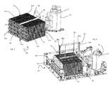
- a heat exchanger casing 7 is shown apt to house both heat exchangers (condenser 31 and evaporator 32) of heat pump 30.
- casing 7 is shown open, with the upper shell detached from the lower shell.
- the basement portion of the process air circuit 18 includes, in addition to the casing 7 for the heat pump 30, a channel 28, located downstream of the casing 7 in the direction of flow of the process air, which channels the process air exiting the condenser 31 of the heat pump 30 outside the basement 24. Channel 28 and casing 7 are visible for example in figure 2 .
- the casing 7 for the heat exchangers 31, 32 includes the bottom surface 7a.
- the moist process air is dehumidified at the evaporator; therefore some water may condense and fall into the bottom surface of the casing 7 under the evaporator.
- a plurality of drain channels are formed, all indicated with 60, which collect the condensed water and brings the latter into a single drain duct 63, preferably running parallel to a lateral wall 25 of casing 2, which in turn preferably brings the condensate water to a water collecting housing 64.
- the bottom surface 7a is realized as an integral part of the lower shell 24b.
- the laundry dryer 1 of the invention further includes the condensed-water housing 64 (partially visible in figure 4 and 5 ) which collects the condensation water produced, when the dryer 1 is in operation, by evaporator 32 by condensation of the surplus moisture in the process air stream arriving from the drum.
- the housing is located at the basement 24.
- the collected water in the housing 63 is sent in a reservoir 9 located in correspondence of the highest portion of the dryer 1 so as to facilitate a comfortable manual discharge of the water by the user of the dryer 1.
- drain duct 63 is located in proximity of one of the lateral side of the basement 24, that, is between the heat pump 30 and the boundary of the basement 3, and brings water to the housing 64.
- the drain channels 60 running on bottom surface 7a are preferably inclined with respect to the horizontal plane (X, Y), so that condensation water by gravity flows from the channels 60 to the main duct 63 leading to housing 64.
- the drain channels 60 therefore preferably include a bottom surface 61 which is inclined or tilted with respect to the horizontal plane.
- drain duct 63 ends in water collecting housing 64 defining an inlet 65 for the condensed water.
- duct 63 is slightly vertically tilted, so that water flows to water collecting housing 64 by gravity.
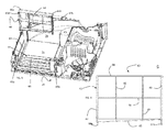
- heat pump 30 includes the two heat exchangers 31, 32 one facing the other in series in the direction of the process air flow and are located in correspondence of the process air conduit 18 formed in the basement 24.
- both evaporator and condenser are positioned on the bottom surface 7a of the casing 7 in the process air conduit 18 and are spaced apart by a gap 50 having advantageously a uniform width W.
- the gap 50 defines the width W in the direction of flow of the process air.
- the process air first passes through the evaporator 32, it then exits the latter, passes through the gap 50 running for a distance W and then enters the condenser 31.
- the gap is delimited by two surfaces, a first surface 51 of the condenser 31 and a second surface 52 of the evaporator 32.
- the first and second surfaces 51, 52 are substantially vertical and even more preferably they are parallel one to the other.
- first and second surface 51, 52 lateral surfaces 31a, 31b and 32a, 32b depart.
- the lateral surfaces are substantially perpendicular to the first or second surface, 51, 52 respectively.
- Each heat exchanger is thus substantially parallelepiped-shaped.
- the first and the second surface 51, 52 are substantially perpendicular to the main direction of the process air within the air process circuit 18.
- a grid 40 is interposed in the gap 50 between the first and the second heat exchangers.
- the grid 50 preferably substantially occupies the whole gap 50, that is, the dimensions of the grid are such that the whole free space between the first and the second surface is filled by the grid itself.
- FIG 3 the heat pump 30 with the grid 40 inserted in the gap 50 between the first and second heat exchangers 31, 32 is shown. This is the operative position during the normal functioning of the dryer 1.
- the grid 40 extracted from the gap 50 is shown to better display the gap 50.
- the basement 24 without heat pump 30 but with grid 50 is depicted as well.
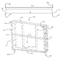
- grid 40 is realized in polymeric material.
- Grid 40 includes a boundary frame 41 delimiting its outer dimensions. When mounted, the grid preferably closes the gap 50 substantially completely, that is, the boundary frame 41 is in abutment to the first and the second surface 51, 52 at least for a portion of the same.
- the grid 40 is substantially a parallelepiped, wherein the boundary frame forms a mantle having a rectangular cross-section.
- the mantle includes four bars. Two of the four bars are parallel to each other and are called lateral first and second bars 42, 43. These first and second lateral bars are substantially vertical and - when the grid is mounted - substantially form a geometrical continuation of the lateral surfaces 31a, 31b and 32a, 32b of the first and second heat exchangers 31, 32. In this way the process air is confined in a channel and cannot leak from it, leakage which may cause pressure drops in the process air conduit. Further, due to the fact that the boundary frame 41 is surrounding the boundaries of the first and the second surfaces 51, 52, substantially the whole process air exiting the evaporator from the second surface enters the condenser at the first surface.
- the boundary frame 41 includes a top and bottom bars 44, 45.
- Top bar 44 is preferably substantially horizontal and more preferably it forms a geometrical continuation of top surfaces 31c and 32c of the first and the second heat exchangers 31, 32, respectively. That is to say that the height at which the top bar 44 is positioned is the height of the boundaries of first and second surfaces 51 and 52. The top bar 44 therefore delimits the process air flow exiting the first surface 51 and entering the second surface 52 from above.
- the bottom bar 45 is preferably tilted, that is, inclined with respect to the horizontal plane (X, Y). This inclination is better visible in the front view of the grid 40 of figure 8 .
- the first and/or second lateral bar includes a plurality of reinforcing ribs 8, as shown in figure 9.
- the bottom bar 45 When grid 40 is mounted in gap 50, the bottom bar 45 preferably abuts onto the lower shell 24b of the basement 24, more preferably on the bottom surface 7a, and even more preferably onto a bottom surface 61 of one of the drain channels 60 which is located at the bottom of gap 50.
- This bottom surface 61 of the drain channel 60 as described above, is tilted with respect to the horizontal plane (X, Y) and therefore, in order to obtain a correct and stable contact between the bottom bar 45 and the bottom surface 61 of the drain channel, the bottom bar 45 is preferably following the slope of the bottom surface 61.
- the inclination of the bottom surface 61 and of the bottom bar 45 is therefore preferably the same.
- Some process air from the first surface 51 may enter the drain channel 60 because the bottom bar does not follow the boundary of the first and the second surfaces 51, 52 however the process air possibly lost is a minimal component of the whole process air flux.
- the grid 40 is then blocked in the position of abutment in the gap 50 by means of a first and a second pin 64a and 64b protruding from the first and second lateral bars 42, 43, respectively.
- Pins 64a, 64b are preferably substantially cylindrical and preferably extend from their respective lateral bar 42, 43 along the Z direction.
- the first and second pins 64a, 64b enter respective first and second seats 65a, 65b realized on the surface 7a, preferably on the bottom surface 61 of the drain channel 60.
- the seats 65a, 65b are so formed that they are shape-matched with the pins 64a, 64b.
- Bottom bar 45 comprises advantageously two different portions tilted in two different directions, that is, it is tilted for a portion with respect to a first axis belonging to the horizontal plane, and for another portion also with respect to a second axis belonging to the (X, Y) plane, the first and second axes being substantially perpendicular.
- This double inclination is created in order to follow the geometrical shape of the bottom surface 61 of drain channel 60, which includes a ramp 66 to drain water collected below the condenser. This ramp is inclined with respect to the (X, Y) plane.
- the bottom surface 61 is thus formed by two portions. A first portion lies on a plane which is rotated with respect to the horizontal plane around a first axis belonging to the (X, Y) plane.
- the second portion which brings water towards the drain duct 63, lies on a plane which is rotated with respect to the horizontal plane around a second axis belonging to the (X, Y) plane, however the first and second axis are substantially perpendicular.
- the grid 40 in order to form a plurality of channels or duct for the process air, includes a plurality of further bars. Some of these bars connect the first and second lateral bars 42, 43 and are preferably parallel to the top bar 44, such as additional bar 48. Other additional bars connect the top and the bottom bars 44, 45, and are preferably parallel to the lateral bars 42, 43, such as additional bars 49.
- the grid thus forms six channels arranged in two rows and three columns.
- the topmost row includes three channels having a rectangular cross section along a plane perpendicular to the process air flow.
- the lowermost row includes three channels having a trapezoid cross section along a plane perpendicular to the process air flow.
- first and second lateral bars 42, 43 protrude from the gap 50.
- Each lateral bar 42, 43 includes two protrusions, first and second, 46a, 47a and 46b, 47b, respectively.
- the first protrusions 46a, 46b are extending in direction of the first heat exchanger, while the second protrusions 47a, 47b are extending in direction of the second heat exchanger.
- the first protrusions 46a, 46b preferably run adjacent to the lateral surfaces 31a, 31b of the first heat exchanger, while the second protrusions 47a, 47b run adjacent to the lateral surfaces 32a, 32b of the second heat exchanger.
- the first protrusions 46a, 46b form therefore a seat in which the first heat exchanger 31 is inserted.
- the dimension of the first heat exchanger that is, its breath, is substantially equal or slightly smaller to the distance between the first protrusion 46a of the first lateral bar and the first protrusion 46b of the second lateral bar.
- the difference between the breath of the first heat exchanger and the distance between the two first protrusions 46a, 46b is at most equal to 1 cm.
- the second protrusions 47a, 47b form a seat in which the second heat exchanger 32 is inserted.
- the dimension of the second heat exchanger is substantially equal or slightly smaller to the distance between the second protrusion 47a of the first lateral bar and the second protrusion 47b of the second lateral bar.
- the difference between the breath of the second heat exchanger and the distance between the two second protrusions 47a, 47b is at most equal to 1 cm. In this way, lateral movements of the first and/or second heat exchanger are prevented.
- the extension of the first and/or second protrusions 46a, 46b; 47a, 47b is rather limited when compared with the extension of the lateral surfaces of the heat exchangers.
- the first protrusions 46a, 46b are flap-shaped, while the second protrusions 47a, 47b are preferably rod-shaped.
- the first and second protrusions 46a, 47a in the first lateral bar 42 are better seen in the lateral view of the grid 40 shown in figure 9.
- first and/or second protrusions are realized integral with the first and/or second lateral bar 42, 43.
- the first and second protrusions 46a, 47a in the first lateral bar 42 are realized at one axial end of the bar. More preferably, the axial end from which the protrusions depart is the top-most end of the bar. The bar is thus, on a lateral view, T-shaped.
- the first and second protrusions 46b, 47b in the second lateral bar 43 extend from the top-most end of the bar, so that the second lateral bar is T-shaped as well.
Landscapes
- Engineering & Computer Science (AREA)
- Textile Engineering (AREA)
- Detail Structures Of Washing Machines And Dryers (AREA)
- Drying Of Solid Materials (AREA)
Abstract
o A treating chamber where items are introduced and treated with a process medium;
o a heat pump (30) system having a refrigerant circuit (38) in which a refrigerant can flow, said refrigerant circuit (38) including a first heat exchanger (31) where the refrigerant is cooled off, a second heat exchanger (32) where the refrigerant is heated up, a compressor (33) to pressurize and circulate the refrigerant through the refrigerant circuit, and a pressure-lowering device (34); said first and/or second heat exchanger being apt to perform heat exchange between said refrigerant flowing in said refrigerant circuit (38) and said process medium;
characterized in that it further includes
o a grid (40) interposed between said first and said second heat exchanger (31, 32) so that said process medium flowing through the second heat exchanger is at least partially guided toward the first heat exchanger.
Description
- The present invention relates to a heat pump dryer. The dryer of the invention has an increased efficiency when compared with heat pumps of the prior art.
- Most dryers consist of a rotating drum called a tumbler, through which heated air is circulated to evaporate the moisture from the load. The tumbler is rotated around its axis.
- Known laundry dryer includes two categories: condense laundry dryers and vented laundry dryers. Dryers of the first category circulate air exhausted from the drum through a heat exchanger/condenser to cool the air and condense the moisture; they subsequently re-circulate the air back through the drum, after having heated the same using a heater. Dryers of the second category draw air from the surrounding area, heat it, blow it into the drum during operation and then exhaust it through a vent into the outside.
- Generally, dryer of the first category are the most common in the market, due to the fact that they do not require special means for proper installation such as an exhaust duct to exhaust the humid hot air coming from the drum. However, commonly, for the same power and the same amount of load, the drying cycle of a condensed dryer is longer than an equivalent cycle in a vented dryer.
- Several solutions have been proposed according to the prior art in order to improve the efficiency of condense and vented dryers. In particular, heat pump technology has been applied to laundry dryer in order to enhance the efficiency in drying clothes. In traditional heat pump drier, air flows in a close loop. The air, moved by a fan, passes through a drum removing water from wet clothes, and then it is cooled down and dehumidified in a heat pump evaporator and heated up in a heat pump condenser to be re-inserted into the drum. In order to function, the heat pump includes a refrigerant with which the air is in thermal exchange, and the refrigerant is compressed by a compressor, condensed in the condenser laminated in an expansion device and then vaporized in the evaporator.
- It is desired to also improve the efficiency of the heat pump dryers themselves. The efficiency of the heat pump dryer depends on several parameters which can influence the energy consumption and the drying time. It is desirable to achieve a so called steady state, which represents an optimum operation state in which the dehumidifying capacity of the evaporator and the heating capacity of the condenser are optimized in view of drying the laundry and energy consumption of the heat pump system.
- A first goal of the present invention is to realize a heat pump dryer having a high efficiency. Further, a goal of the invention is to obtain such an increased efficiency without increasing, or increasing only in a minor way, the costs of manufacturing of the dryer and its assembly time.
- In a heat pump dryer, process air flows in a process air circuit which includes the drum, in order to dry the laundry. The humid process air exits the dryer, for example from the front part, and is directed towards the heat pump where it is dried and heated, so that it can return to the drum to continue the drying cycle.
- A loss in performances during the drying cycle is due - among others - to the loss of process air which escapes the process air circuit. In particular, when process air reaches the heat pump, it is dehumidified by the evaporator and then heated up by the condenser. If process air which has passed through the evaporator and has exited the latter does not reach the condenser, but, due to turbulences or non-straight trajectories of the air flow path, it is diverted somewhere else, energy which has been used to dehumidify and blow this diverted process air is lost, because this diverted process air does not contribute any more to the drying process. Further, chaotic air paths and turbulences of the air flow path reduce the heat exchange between the process air and the evaporator and/or condenser.
- Applicants have therefore realized that it is important to properly direct the process air exiting the evaporator towards the condenser.
- According to an aspect, the invention relates to a drying appliance including
- o A treating chamber where items are introduced and treated with a process medium;
- o a heat pump system having a refrigerant circuit in which a refrigerant can flow, said refrigerant circuit including a first heat exchanger where the refrigerant is cooled off, a second heat exchanger where the refrigerant is heated up, a compressor to pressurize and circulate the refrigerant through the refrigerant circuit, and a pressure-lowering device; said first and/or second heat exchanger being apt to perform heat exchange between said refrigerant flowing in said refrigerant circuit and said process medium;
characterized in that it further includes - o a grid interposed between said first and said second heat exchanger so that said process medium flowing through the second heat exchanger is at least partially guided toward the first heat exchanger.
- The appliance of the invention may be preferably a dryer or a washer dryer.
- A heat pump appliance includes a treating chamber, such as a drum, in which the load of laundry, e.g., clothes, or other items to be washed and/or dried are placed. The treating chamber is part of a process air circuit, in particular for example a closed-loop air circuit in case of a condensed dryer or an open air circuit in case of a vented dryer, which in both cases includes an air duct for channelling a stream of air to dry the load. The process air circuit is connected with its two opposite ends to the treating chamber. For example, hot dehumidified air is fed into the treating chamber, flowing over the laundry, and the resulting humid cool air exits the same. The humid air stream rich in water vapour is then fed into an evaporator of a heat pump, where the moist warm process air is cooled and the humidity present therein condenses. The resulting cool dehumidified air is then either vented outside the appliance in the ambient where the latter is located or it continues in the closed-loop circuit. In this second case, the dehumidified air in the process air circuit is then heated up before entering again in the drying chamber by means of a condenser of the heat pump, and the whole loop is repeated till the end of the drying cycle. Alternatively, ambient air enters into the drum from the ambient via an inlet duct and it is heated up by the condenser of the heat pump before entering the drying chamber. Different circuits are known in the art in case of a washer-dryer.
- The heat pump of the appliance further includes a refrigerant circuit in which a refrigerant can flow and which connects via piping the first heat exchanger or condenser, the second heat exchanger or evaporator, a compressor and a pressure-lowering device. The refrigerant is pressurized and circulated through the system by the compressor. On the discharge side of the compressor, the hot and highly pressurized vapour is cooled in the condenser, until it condenses into a high pressure, moderate temperature liquid, heating up the process air before the latter is introduced into the drying chamber. The condensed refrigerant then passes through the pressure-lowering device such as an expansion device, e.g., a choke, a valve or a capillary tube. The low pressure liquid refrigerant then enters the evaporator, in which the fluid absorbs heat and evaporates due to the heat exchange with the warm process air exiting the drying chamber. The refrigerant then returns to the compressor and the cycle is repeated.
- Preferably, the dryer includes a casing including walls delimiting the dryer and mounted on a basement located at the bottom of the dryer. Preferably, the heat pump is mounted within the basement of the dryer. Advantageously, the basement is formed by an upper and lower shell. The upper and lower shells define a casing to contain the first and the second heat exchanger of the heat pump.
- Advantageously, each heat exchanger, the evaporator or the condenser, includes a bottom surface facing the basement, an upper surface substantially parallel to it facing upwards and four lateral surfaces. A lateral surface of the condenser faces a lateral surface of the evaporator, due to the fact that preferably the first and second heat exchangers are positioned in series within the process air circuit, one in front of the other, along the flow path of the process air circuit. The heat exchangers preferably are not in contact with each other.
- In the following, with the terms "downstream" and/or "upstream", a position with reference to the direction of the flow of a fluid inside a conduit is indicated. Additionally, in the present context, the terms "vertical" and "horizontal" are referred to the positions of elements with respect to the dryer in its normal installation or functioning. Indeed, a horizontal plane (X,Y) formed by two horizontal X,Y perpendicular directions is defined, and a vertical direction Z, perpendicular to the horizontal plane, is defined as well in a 3-D space, by the ground on which the dryer is resting. However, the same definition applies when the ground is not really horizontal, but tilted with respect of the same. Also in this case, all spatial terminology like "upper", "lower", "lateral" can be still used, referring to a local coordinate system where the plane (X,Y) is a locally horizontal plane on which the dryer rests and Z the locally vertical coordinate along which the dryer extends.
- Applicants have realized that, in addition to the proper choice of refrigerant and compressor, also the design of the heat exchangers, i.e. namely of the evaporator and the condenser, can severely affect energy consumption and drying time performances. In particular, a proper mutual configuration of the heat exchanger(s) allows achieving several benefits, such as maximizing the heat exchange between the refrigerant and the process air, reducing the pressure drop both in the refrigerant and in the process air circuit, and reducing the amount of refrigerant needed for a proper functioning of the heat pump. All these benefits allow saving energy, reduce the drying cycle duration and, in general, allow the realization of a more "ecofriendly" dryer.
- This improvement is achieved positioning a grid between the evaporator and the condenser. The evaporator is part of the process air circuit and it is hit by the humid process air on one side. The process air passes through the evaporator and exits on the opposite side after having exchanged heat with the evaporator, in particular after having been cooled down and dehumidified. At the exit of the evaporator, the process air flow enters the grid, which further guides the process air exiting the evaporator of the heat pump towards the condenser. The grid therefore, with its guiding properties, limits or minimizes the amount of process air that is lost in the transfer from evaporator to condenser. Further, the grid helps to "straighten" the flux lines of the process air flow, so that less turbulences and chaotic behavior occurs inside the condenser. A substantially straight air flow increases the efficiency of the heat exchange between the process air and the refrigerant at the condenser, so that the process air is efficiently heated up and the drying time is reduced.
- The grid is defined as a framework of spaced bars that are crossing each other. A grid is herein used as a synonym of a grating or mesh. The grid forms a pattern of spaced horizontal and vertical bars forming a plurality of channels having each a polygonal cross-section along the process air flow direction. Each of these polygons formed by intersecting bars has the function of a channel to direct the process air towards the condenser. The geometrical shape of the channel is arbitrary; they can - in cross - section - include squares, rectangles, rhombus, etc. The grid includes at least two channels.
- Preferably, the grid extends vertically between the two heat exchangers.
- According to the above mentioned aspect, the dryer of the invention may include in addition or alternatively any of the following characteristics.
- Preferably, the first heat exchanger comprises a first surface and the second heat exchanger comprises a second surface facing said first surface, said grid being dimensioned so that it overlaps the majority of said first and/or second surface.
- The layout of the heat pump is such that the evaporator faces the condenser in the direction of flow of the process air in the process air conduit. A lateral surface of the condenser facing a lateral surface of the evaporator is called first surface while the lateral surface of the evaporator is called second surface. In its flow, the process air exits the evaporator from the second surface and enters the condenser via its first surface. The dimensions of the grid are preferably such that, when inserted between the first and the second surfaces, it extends so as to cover the majority of the first and/or the second surface, more preferably the whole first and/or second surface, in order to channel most of the process air exiting the evaporator towards the condenser. The projection of the grid onto the first and/or onto the second surface therefore preferably covers most of the first and/or second surface, more preferably they superimpose substantially completely.
- In an embodiment, the dimensions of the grid are bigger than those of the first and/or second surface, so that the grid extends for example within the basement, such as in a condensate water drain channel apt to collect and drain the condensation water which generally forms under the evaporator.
- Advantageously, said first and second heat exchangers form a gap therebetween having a gap width, and wherein said grid is inserted in said gap, the grid including a boundary frame having a first and a second lateral bars, said first and second bars being wider, at least for a portion, than the gap width.
- The evaporator and the condenser are not in contact to each other, but they are separated by a gap, of a given width W. In the same way, the first and second surfaces are separated one from the other by the same gap having width W. The width does not have to be constant, but it can vary. For example, one portion of the first surface could be closer to the second surface than a second portion. The gap in this case, seen from above, could have a wedge shape. Preferably, the gap has a substantially uniform width. The grid is inserted in this gap.
- The grid includes a boundary frame that delimits the outer boundaries of the grid. Inside the grid additional bars divide the grid in channel. The boundary frame also includes bars, such as a first and a second lateral bars. The first and the second lateral bars are substantially perpendicular to the (X, Y) plane, or at least a projection of the lateral bars onto the (X, Y) plane is much smaller than the projection of the bars in a plane perpendicular to the (X, Y) plane.
- The lateral bars are wider than the width of the gap, regardless of whether the gap width is constant or not. To be wider, the lateral bars need to protrude, at least for a portion, from the gap; otherwise they would penetrate the first and/or second heat exchanger. Therefore, the lateral bars extend along the lateral surfaces of the evaporator and/or condenser. The lateral surfaces along which the bars extend are the lateral surfaces substantially perpendicular to the first and/or second surface.
- In this embodiment, therefore, preferably the lateral bars are surrounding from both sides a portion of the evaporator and/or a portion of the condenser. Preferably, the lateral bars both surrounds a portion of the evaporator and of the condenser. Advantageously, the lateral bars extend for a minor portion of the lateral surfaces of the evaporator and/or condenser.
- More preferably, said first and second lateral bars include each a first projection, said first projections extending towards said first heat exchanger, the first projection of the first bar being spaced apart from the first projection of the second bar so as to form a seat therebetween for receiving the first heat exchanger.
- Even more preferably, a length difference between a distance between the first projection of the first lateral bar and the first projection of the second lateral bar and a breadth of said first heat exchanger along a line connecting said first projection of said first lateral bar and said first projection of said second lateral bar is equal to or smaller than 1 cm.
- As already mentioned, the grid includes a boundary frame having lateral bars. The frame forms substantially a C shape, where the two arms of the C partially embrace a portion of the condenser. The center of the C is the portion of the grid interposed in the gap between the two heat exchangers. The C arms are realized by the first projections or flaps extending one each from the first and the second lateral bar. Preferably, the distance between the projections is substantially identical or only slightly bigger than the breath of the heat exchanger. Therefore, the heat exchanger is inserted between the two projections and its possible lateral movements are substantially prevented by the presence of the projections of the lateral bars belonging to the grid. In this way, the heat exchanger remains substantially in its position, because lateral movements are hindered, blocked by the lateral bars. This avoids both vibrations of the heat exchanger and the corresponding noise due to the vibrations themselves. The vibrations could be due to the drum rotations during the drying cycles.
- Advantageously, said first and second lateral bars include each a second projection, said second projections extending towards said second heat exchanger, the second projection of the first lateral bar being spaced apart from the second projection of the second lateral bar so as to form a seat therebetween for receiving the first heat exchanger.
- More preferably, a length difference a distance between the second projection of the first lateral bar and the second projection of the second lateral bar and a breadth of said second heat exchanger along a line connecting said second projection of said first lateral bar and said second projection of said second lateral bar is equal to or smaller than 1 cm.
- The lateral bars instead or in addition to the condenser may embrace a portion of the evaporator and form a seat by means of the two projections which is C shaped. The above considerations made for the condenser applies here for the evaporator as well. In case both the evaporator and the condenser are surrounded by the lateral first and second bars, the bars form a double C, each C facing a different heat exchanger.
- In an embodiment, said first and/or second lateral bar is T shaped, and said first and/or second projection is extending from an end of said first and/or second lateral bar.
- The first and/or second lateral bar includes two projections, one to partially embrace the evaporator and the other to partially embrace the condenser, in cooperation with the projections of the other of the second and/or first lateral bar. The lateral bars are preferably vertically positioned and they define two axially opposite ends, a top end and a bottom end. The projections extend from one of the axial ends of the lateral bar, preferably from the top end, so that each lateral bar has substantially a T shape.
- Preferably, the dryer of the invention includes a basement and a drain channel realized in a bottom surface of said basement, wherein said drain channel is located below the second heat exchanger and/or the first heat exchanger, providing the condensate water to flow away from the second and/or first heat exchangers, said grid being inserted into said drain channel and resting on a bottom surface of said drain channel. Advantageously, the basement also includes a water collecting housing, which is apt to collect the water which condenses due to the presence of the evaporator within the air process circuit. Indeed, the evaporator dehumidifies the process air and thus condensation process water can drip from the evaporator surfaces onto the basement. This water is thus collected into the water collecting housing by means of a drain channel which is also realized in the bottom surface of the basement below the evaporator and possibly also below the condenser. The drain channel preferably extends also within the gap between the two heat exchangers.
- Preferably, the drain channel may include a single channel or a plurality of channels connecting the location where the condensed water is formed, for example a surface or basin below the evaporator where water drips, to the water collecting housing. Preferably, the drain channel includes a plurality of channels which merge into a single duct when they emerge from below the evaporator.
- Preferably, the evaporator is located within the basement. Preferably, such drain channel to channel the condensed water to the water collecting housing is realized integral to said basement. Preferably, the surface or basin onto which the condensed water drips is also integral to the basement.
- The drain channel is also present at least for a portion in the gap between the first and the second heat exchanger. The grid is in abutment with a bottom surface of the drain channel. It is preferred that the grid is supported by the basement to give stability to it.
- In the present context, with the terms "realized integral to" mean that the element discussed is realized as a single unit together with another element, without discontinuities. A first element realized integral to a second element thus means that the two are a single piece, a unitary body.
- Advantageously, said grid includes a boundary frame having a top and a bottom bars, said top and bottom bars being inclined one with respect to the other.
- More preferably, said bottom surface of said drain channel is inclined with respect to a plane (X, Y) on which the appliance rests and said bottom bar of said boundary frame is also inclined with respect to the plane (X, Y) so as to abut onto the bottom surface of the drain channel.
- Preferably, the drain channel is inclined with respect to the plane on which the dryer rests. This inclination allows a quicker and easy outflow of the condensation water towards for example the water collecting housing. Due to the fact that to enhance stability the grid is in abutment to the bottom surface of the drain channel with its bottom bar, also the bottom bar is advantageously inclined so that it can follow the slope of the bottom surface of the drain channel.
- In an embodiment, said first and second heat exchangers form a gap (50) therebetween having a gap width, and wherein said grid is inserted in said gap, the grid including a boundary frame having a top and a bottom bars, said top and/or said bottom bar having a width substantially identical to said gap width (W).
- The lateral bars of the grid may project outside the gap, to hold the heat exchangers in position, while the top and bottom bars are inserted within the gap and preferably, in order to avoid process air leakage, have a width equal to the width of the gap, to properly confine the process air within the grid while process air is travelling from the evaporator to the condenser.
- Advantageously, said first and second surfaces are substantially perpendicular to a plane (X, Y) on which the appliance rests.
- The first and second heat exchangers are preferably positioned on the basement with their respective bottom surfaces substantially parallel to the ground and then they extends vertically in such a way that their first surface and second surface are substantially vertical, that is, perpendicular to the ground.
- Preferably, said grid includes a boundary frame having a first and a second lateral bars and a top and a bottom bars connecting said first and second lateral bars, and the grid further includes at least an additional bar connecting said first and second lateral bars and positioned between said top and bottom bars.
- Preferably, said grid includes a boundary frame having a first and a second lateral bars and a top and a bottom bars connecting said first and second lateral bars, and the grid further includes at least an additional bar connecting said top and bottom bars and positioned between said first and second lateral bars.
- In order to form the channels for the process air, the grid not only includes the boundary frame, but also additional bars positioned internally to the boundary frame to divide the boundary frame in portions, each portion forming a channel for the process air. The number of additional internal bars is arbitrary. Preferably, the additional internal bars connecting the top and bottom bars of the boundary frame are substantially parallel to the lateral bars, while preferably the additional bars connecting the lateral bars of the boundary frame are substantially parallel to the top bar.
- Advantageously, said first heat exchanger comprises a first surface and said second heat exchanger comprises a second surface facing said first surface, and between said first and a said second surface a gap therebetween having a gap width is formed, and wherein said grid is inserted in said gap, said grid abutting on the first surface on one side and on the second surface on the other side so that process air exiting the second heat exchanger is guided to enter the first heat exchanger.
- The grid substantially occupies the entire gap between the first and the second heat exchangers. In this way, the losses of process air are minimized and, in turn, also pressure drops in the process air circuit are minimized as well. If the grid is in contact to the first and the second surfaces, it means that the process air experiences a substantially continuous channel from the exit of the evaporator to the inlet of the condenser. The process air flux in addition is regularized by the plurality of channels formed within the grid.
- Preferably, the drying appliance of the invention includes a basement having a bottom surface in which first and a second seats are formed and wherein said grid includes a boundary frame from which a first and a second pins extend, said first and second pins being inserted into said first and second seats, respectively.
- More preferably, said basement includes a drain channel and said first and second seats are formed in a bottom channel of said drain channel.
- Advantageously the grid is in abutment to the basement and more preferably to the bottom surface of the drain channel. However, the dryer might vibrate due to the rotation of the drum during the drying cycles. To avoid that these vibration might misplace the grid positioned in the gap between the two heat exchangers, preferably the grid is fixed in an optimal desired position. This fixing is performed by a coupling of two pins formed in the grid with two correspondingly formed seats in the basement, and more preferably in the drain channel, of the dryer. Preferably, the pins are realized integral to the lateral bars.
- The accompanying drawings, which are included to provide a further understanding of the invention and are incorporated in and constitute a part of this specification, illustrate possible embodiments of the invention and together with the description serve to explain the principles of the invention. In the drawings, corresponding characteristics and/or components are identified by the same reference numbers. In particular:
-
Figure 1 shows a perspective view of a laundry drying machine realized according to the invention; -
Figure 2 shows a perspective view of a basement of the laundry drying machine illustrated infigure 1 ; -
Figure 3 shows a perspective view of a heat pump located in the basement offigure 2 ; -
Figure 4 shows a perspective view the basement offigure 2 with some elements removed; -
Figure 5 shows a perspective view of the basement offigure 4 where the heat pump has been removed; -
Figure 6 shows a perspective view of a grid used in the heat pump offigure 3 ; -
Figure 7 shows a top view of the grid offigure 6 ; -
Figure 8 shows a front view of the grid offigure 6 ; and - Figure 9 shows a lateral view of the grid of
figure 6 . - With initial reference to
Fig. 1 , a laundry dryer realized according to the present invention is globally indicated with 1. - Although the present description refers to a dryer, the appliance of the invention could comprise a dryer or a combined washer-dryer.
-
Laundry dryer 1 comprises an outer box orcasing 2, preferably but not necessarily parallelepiped-shaped, and a treating chamber, such as a drum (not visible in the drawings), for example having the shape of a hollow cylinder, closed or not on one side, for housing the laundry and in general the clothes and garments to be dried. The drum is preferably rotatably fixed to thecasing 2, so that it can rotate around a preferably horizontal axis (in alternative embodiments, rotation axis may be tilted). Access to the drum is achieved for example via adoor 4, preferably hinged tocasing 2, which can open and close an opening realized on the cabinet itself. - More in detail, casing 2 generally includes a
front wall 20, a rear wall 21 and twolateral walls 25, all mounted on abasement 24. Preferably, thebasement 24 is realized in polymeric material. Preferably,basement 24 is molded via an injection molding process. Preferably, on thefront wall 20, thedoor 4 is hinged so as to access the drum. The cabinet, with its walls, defines the volume of thelaundry dryer 1. Advantageously,basement 24 includes an upper and alower shell portion Figure 2 detailed below). - The
dryer 1, and inparticular basement 24, defines an horizontal plane (X,Y) which is substantially the plane of the ground on which thedryer 1 is situated, and a vertical direction Z perpendicular to the plane (X, Y). In case the ground is tilted with respect to a real horizontal plane, the (X, Y) plane is still called horizontal in a local coordinate system. -
Laundry dryer 1 also preferably comprises anelectrical motor assembly 50 for rotating, on command, revolving drum along its axis insidecabinet 2.Motor 50 includes ashaft 51 which also rotates an air process fan or blower 12 (seefigure 2 ). - Further,
laundry dryer 1 may include an electronic central control unit 100 (schematically visible infigure 1 ) which controls both theelectrical motor assembly 50 and other components of thedryer 1 to perform, on command, one of the user-selectable drying cycles preferably stored in the same central control unit. The programs as well other parameters of thelaundry dryer 1, or alarm and warning functions can be set and/or visualized in acontrol panel 11, preferably realized in a top portion of thedryer 1, such as abovedoor 4. -
Dryer 1 additionally includes a process air circuit which comprises the drum and anair process conduit 18, depicted as a plurality of arrows showing the path flow of a process air stream through the dryer 1 (seefigure 2 ). In thebasement 24, a portion of theair process conduit 18 is formed by the connection of theupper shell 24a and thelower shell 24b.Air process conduit 18 is preferably connected with its opposite ends to two opposite sides of drum. Process air circuit also includes the fan or blower 12 (shown infig. 2 ), preferably operated bymotor 50, which blows process air within the circuit. - With now reference to
figs. 2 - 4 , thedryer 1 of the invention additionally comprises a process air generator, in the depicted embodiment aheat pump system 30 including a first heat exchanger (called also condenser) 31 and a second heat exchanger (called also evaporator) 32.Heat pump 30 also includes a refrigerant closed circuit (partly depicted) in which a refrigerant fluid flows, when thedryer 1 is in operation, cools off and may condense in correspondence of thecondenser 31, releasing heat, and warms up, in correspondence of the second heat exchanger (evaporator) 32, absorbing heat. Acompressor 33 receives refrigerant in a gaseous state from theevaporator 32 and supplies thecondenser 31, thereby closing the refrigerant cycle. In the following the heat exchangers are named either condenser and evaporator or first and second heat exchanger, respectively. More in detail, the heat pump circuit connects via piping 35 (seeFig. 2 ) the second heat exchanger (evaporator) 32 via thecompressor 33 to thecondenser 31. The outlet ofcondenser 31 is connected to the inlet of theevaporator 32 via an expansion device (not shown), such as a choke, a valve or a capillary tube. - It is to be understood that in the
dryer 1 of the invention, an air heater, such as an electrical heater, can also be present, in addition to theheat pump 30. In this case,heat pump 30 and heater can also work together to speed up the heating process (and thus reducing the drying cycle time). - Circulation of the process drying air inside the drum evaporates the moisture from the wetted laundry so as to form a moisture-laden process air, or moist process air. The moist process air then exits the drum preferably at the front side of the
dryer 1, as depicted infigure 2 by a vertical arrow. With reference tofig. 2 , the moist process air enters into thebasement 24 through opening 19in and flows through theevaporator 32, where the moisture included in the process air is at least partially removed. - In the
circuit 18 depicted, the condenser is in series positioned downstream of the evaporator, so that moist process air passes theevaporator 32 and then thecondenser 31 one after the other. The evaporator condenses the water vapor of the moist process air and the water formed therein falls in abottom surface 7a ofbasement 24, better detailed below. The process air then passes thecondenser 31, exits thebasement 24, preferably from the back of the basement, and then it is fed again to the drum. - In
figure 2 , aheat exchanger casing 7 is shown apt to house both heat exchangers (condenser 31 and evaporator 32) ofheat pump 30. In the figure,casing 7 is shown open, with the upper shell detached from the lower shell. The basement portion of theprocess air circuit 18 includes, in addition to thecasing 7 for theheat pump 30, achannel 28, located downstream of thecasing 7 in the direction of flow of the process air, which channels the process air exiting thecondenser 31 of theheat pump 30 outside thebasement 24.Channel 28 andcasing 7 are visible for example infigure 2 . - The
casing 7 for theheat exchangers bottom surface 7a. As mentioned, the moist process air is dehumidified at the evaporator; therefore some water may condense and fall into the bottom surface of thecasing 7 under the evaporator. In thebottom surface 7a of the casing, and preferably belowevaporator 32, a plurality of drain channels are formed, all indicated with 60, which collect the condensed water and brings the latter into asingle drain duct 63, preferably running parallel to alateral wall 25 ofcasing 2, which in turn preferably brings the condensate water to awater collecting housing 64. - Preferably, the
bottom surface 7a is realized as an integral part of thelower shell 24b. - Preferably, the
laundry dryer 1 of the invention further includes the condensed-water housing 64 (partially visible infigure 4 and5 ) which collects the condensation water produced, when thedryer 1 is in operation, byevaporator 32 by condensation of the surplus moisture in the process air stream arriving from the drum. The housing is located at thebasement 24. Preferably, through a connecting pipe and a pump (not shown in the drawings), the collected water in thehousing 63 is sent in a reservoir 9 located in correspondence of the highest portion of thedryer 1 so as to facilitate a comfortable manual discharge of the water by the user of thedryer 1. - Preferably drain
duct 63 is located in proximity of one of the lateral side of thebasement 24, that, is between theheat pump 30 and the boundary of the basement 3, and brings water to thehousing 64. Preferably, thedrain channels 60 running onbottom surface 7a are preferably inclined with respect to the horizontal plane (X, Y), so that condensation water by gravity flows from thechannels 60 to themain duct 63 leading tohousing 64. Thedrain channels 60 therefore preferably include a bottom surface 61 which is inclined or tilted with respect to the horizontal plane. - With now reference to
fig. 5 , drainduct 63 ends inwater collecting housing 64 defining an inlet 65 for the condensed water. In order to better channel condensed water accumulated insurface 7a tohousing 64, preferably alsoduct 63 is slightly vertically tilted, so that water flows to water collectinghousing 64 by gravity. - With reference now to
figures 3 and 4 ,heat pump 30 includes the twoheat exchangers process air conduit 18 formed in thebasement 24. - Preferably, both evaporator and condenser are positioned on the
bottom surface 7a of thecasing 7 in theprocess air conduit 18 and are spaced apart by agap 50 having advantageously a uniform width W. Thegap 50 defines the width W in the direction of flow of the process air. In the process air conduit, as mentioned, the process air first passes through theevaporator 32, it then exits the latter, passes through thegap 50 running for a distance W and then enters thecondenser 31. The gap is delimited by two surfaces, afirst surface 51 of thecondenser 31 and asecond surface 52 of theevaporator 32. Preferably the first andsecond surfaces second surface lateral surfaces second heat exchanger second surface air process circuit 18. - If the
gap 50 were empty, the process air would travel unconfined for a distance W in thegap 50, therefore some process air could not enter the condenser. According to the invention, in thegap 50 between the first and the second heat exchangers, agrid 40 is interposed. Thegrid 50 preferably substantially occupies thewhole gap 50, that is, the dimensions of the grid are such that the whole free space between the first and the second surface is filled by the grid itself. - In
figure 3 , theheat pump 30 with thegrid 40 inserted in thegap 50 between the first andsecond heat exchangers dryer 1. Infigure 4 , thegrid 40 extracted from thegap 50 is shown to better display thegap 50. Further, infigure 5 , thebasement 24 withoutheat pump 30 but withgrid 50 is depicted as well. - Preferably,
grid 40 is realized in polymeric material. - In
figure 6 a perspective view of thegrid 40 alone is shown.Grid 40 includes aboundary frame 41 delimiting its outer dimensions. When mounted, the grid preferably closes thegap 50 substantially completely, that is, theboundary frame 41 is in abutment to the first and thesecond surface - The
grid 40 is substantially a parallelepiped, wherein the boundary frame forms a mantle having a rectangular cross-section. In this preferred embodiment, the mantle includes four bars. Two of the four bars are parallel to each other and are called lateral first andsecond bars lateral surfaces second heat exchangers boundary frame 41 is surrounding the boundaries of the first and thesecond surfaces - Further, the
boundary frame 41 includes a top andbottom bars Top bar 44 is preferably substantially horizontal and more preferably it forms a geometrical continuation oftop surfaces second heat exchangers top bar 44 is positioned is the height of the boundaries of first andsecond surfaces top bar 44 therefore delimits the process air flow exiting thefirst surface 51 and entering thesecond surface 52 from above. Thebottom bar 45 is preferably tilted, that is, inclined with respect to the horizontal plane (X, Y). This inclination is better visible in the front view of thegrid 40 offigure 8 . - In order to strengthen the lateral bars 42, 43, the first and/or second lateral bar includes a plurality of reinforcing
ribs 8, as shown in figure 9. - When
grid 40 is mounted ingap 50, thebottom bar 45 preferably abuts onto thelower shell 24b of thebasement 24, more preferably on thebottom surface 7a, and even more preferably onto a bottom surface 61 of one of thedrain channels 60 which is located at the bottom ofgap 50. This bottom surface 61 of thedrain channel 60, as described above, is tilted with respect to the horizontal plane (X, Y) and therefore, in order to obtain a correct and stable contact between thebottom bar 45 and the bottom surface 61 of the drain channel, thebottom bar 45 is preferably following the slope of the bottom surface 61. The inclination of the bottom surface 61 and of thebottom bar 45 is therefore preferably the same. - Some process air from the
first surface 51 may enter thedrain channel 60 because the bottom bar does not follow the boundary of the first and thesecond surfaces - The
grid 40 is then blocked in the position of abutment in thegap 50 by means of a first and asecond pin Pins lateral bar second pins second seats surface 7a, preferably on the bottom surface 61 of thedrain channel 60. Theseats pins -
Bottom bar 45 comprises advantageously two different portions tilted in two different directions, that is, it is tilted for a portion with respect to a first axis belonging to the horizontal plane, and for another portion also with respect to a second axis belonging to the (X, Y) plane, the first and second axes being substantially perpendicular. This double inclination is created in order to follow the geometrical shape of the bottom surface 61 ofdrain channel 60, which includes aramp 66 to drain water collected below the condenser. This ramp is inclined with respect to the (X, Y) plane. The bottom surface 61 is thus formed by two portions. A first portion lies on a plane which is rotated with respect to the horizontal plane around a first axis belonging to the (X, Y) plane. Also the second portion, which brings water towards thedrain duct 63, lies on a plane which is rotated with respect to the horizontal plane around a second axis belonging to the (X, Y) plane, however the first and second axis are substantially perpendicular. - In addition, in order to form a plurality of channels or duct for the process air, the
grid 40 includes a plurality of further bars. Some of these bars connect the first and second lateral bars 42, 43 and are preferably parallel to thetop bar 44, such asadditional bar 48. Other additional bars connect the top and the bottom bars 44, 45, and are preferably parallel to the lateral bars 42, 43, such asadditional bars 49. In this depicted embodiment, the grid thus forms six channels arranged in two rows and three columns. The topmost row includes three channels having a rectangular cross section along a plane perpendicular to the process air flow. The lowermost row includes three channels having a trapezoid cross section along a plane perpendicular to the process air flow. - In addition, advantageously, first and second lateral bars 42, 43, for a portion thereof, protrude from the
gap 50. Eachlateral bar first protrusions second protrusions first protrusions lateral surfaces second protrusions lateral surfaces first protrusions first heat exchanger 31 is inserted. The dimension of the first heat exchanger, that is, its breath, is substantially equal or slightly smaller to the distance between thefirst protrusion 46a of the first lateral bar and thefirst protrusion 46b of the second lateral bar. The difference between the breath of the first heat exchanger and the distance between the twofirst protrusions second protrusions second heat exchanger 32 is inserted. The dimension of the second heat exchanger, that is, its breath, is substantially equal or slightly smaller to the distance between thesecond protrusion 47a of the first lateral bar and thesecond protrusion 47b of the second lateral bar. The difference between the breath of the second heat exchanger and the distance between the twosecond protrusions second protrusions figure 3 , while the length of the protrusions compared with the grid dimensions can be best appreciated in the top view of thegrid 40 offigure 7 . - Preferably, the
first protrusions second protrusions second protrusions lateral bar 42 are better seen in the lateral view of thegrid 40 shown in figure 9. Preferably first and/or second protrusions are realized integral with the first and/or secondlateral bar second protrusions lateral bar 42 are realized at one axial end of the bar. More preferably, the axial end from which the protrusions depart is the top-most end of the bar. The bar is thus, on a lateral view, T-shaped. Analogously, preferably also the first andsecond protrusions lateral bar 43 extend from the top-most end of the bar, so that the second lateral bar is T-shaped as well.
Claims (18)
- A drying appliance (1) includingo A treating chamber where items are introduced and treated with a process medium;o a heat pump (30) system having a refrigerant circuit (38) in which a refrigerant can flow, said refrigerant circuit (38) including a first heat exchanger (31) where the refrigerant is cooled off, a second heat exchanger (32) where the refrigerant is heated up, a compressor (33) to pressurize and circulate the refrigerant through the refrigerant circuit, and a pressure-lowering device (34); said first and/or second heat exchanger being apt to perform heat exchange between said refrigerant flowing in said refrigerant circuit (38) and said process medium; characterized in that it further includeso a grid (40) interposed between said first and said second heat exchanger (31, 32) so that said process medium flowing through the second heat exchanger is at least partially guided toward the first heat exchanger.
- The drying appliance (1) according to claim 1, wherein said first heat exchanger (31) comprises a first surface (51) and said second heat exchanger (32) comprises a second surface (52) facing said first surface, said grid (40) being dimensioned so that it overlaps the majority of said first and/or second surface.
- The drying appliance (1) according to claim 1 or 2, wherein said first and second heat exchangers (31, 32) form a gap (50) therebetween having a gap width (W), and wherein said grid (40) is inserted in said gap (50), the grid (40) including a boundary frame (41) having a first and a second lateral bars (42, 43), said first and second bars (42, 43) being wider, at least for a portion, than the gap width (W).
- The drying appliance (1) according to claim 3, wherein said first and second lateral bars (42, 43) include each a first projection (46a, 46b), said first projections (46a, 46b) extending towards said first heat exchanger (31), the first projection (46a) of the first lateral bar (42) being spaced apart from the first projection (46b) of the second lateral bar (43) so as to form a seat therebetween for receiving the first heat exchanger (31).
- The drying appliance (a) according to claim 4, wherein a length difference between a distance between the first projection (46a) of the first lateral bar (42) and the first projection (46b) of the second lateral bar (43) and a breadth of said first heat exchanger (31) along a line connecting said first projection (46a) of said first lateral bar (42) and said first projection (46b) of said second lateral bar (43) is equal to or smaller than 1 cm.
- The drying appliance (1) according to claim 3 or 4, wherein said first and second lateral bars (42, 43) include each a second projection (47a, 47b), said second projections (47a, 47b) extending towards said second heat exchanger (32), the second projection (47a) of the first lateral bar (42) being spaced apart from the second projection (47b) of the second lateral bar (43) so as to form a seat therebetween for receiving the second heat exchanger (31).
- The drying appliance (1) according to claim 6, wherein a length difference between a distance between the second projection (47b) of the first lateral bar (42) and the second projection (47b) of the second lateral bar (43) and a breadth of said second heat exchanger (32) along a line connecting said second projection (47a) of said first lateral bar (42) and said second projection (47b) of said second lateral bar (43)is equal to or smaller than 1 cm .
- The drying appliance (1) according to claim 4 or 5, wherein said first and/or second lateral bar (42, 43) is T shaped, and said first and/or second projection (46a, 46b, 47a, 47b) is extending from an end of said first and/or second lateral bar (42, 43).
- The drying appliance (1) according to any of the preceding claims, including a basement (24) and a drain channel (60) realized in said basement, wherein said drain channel (60) is located below the second heat exchanger (32) and/or the first heat exchanger (31), providing the condensate water to flow away from the first and/or second heat exchangers, said grid (40) being inserted into said drain channel (60) and resting on a bottom surface (61) of said drain channel.
- The drying appliance (1) according to any of the preceding claims, wherein said grid (40) includes a boundary frame (41) having a top and a bottom bars (44, 45), said top and bottom bars being inclined one with respect to the other.
- The drying appliance (1) according to any of the preceding claims, wherein said first and second heat exchangers (31, 32) form a gap (50) therebetween having a gap width (W), and wherein said grid (40) is inserted in said gap (50), the grid (40) including a boundary frame (41) having a top and a bottom bars (44, 45), said top and/or said bottom bar (44, 45) having a width substantially identical to said gap width (W).
- The drying appliance (1) according to any of the preceding claims when dependent on claim 2, wherein said first and second surfaces (51, 52) are substantially perpendicular to a plane (X, Y) on which the appliance rests.
- The drying appliance (1) according to any of the preceding claims when dependent on claim 7, wherein said bottom surface (61) of said drain channel (60) is inclined with respect to a plane (X, Y) on which the appliance rests and said bottom bar (45) of said boundary frame (41) is also inclined with respect to the plane (X, Y) so as to abut onto the bottom surface (61) of the drain channel (60).
- The drying appliance according to any of the preceding claims, wherein said grid (40) includes a boundary frame (41) having a first and a second lateral bars (42, 43) and a top and a bottom bars (44, 45) connecting said first and second lateral bars (42, 43), and the grid (40) further includes at least an additional bar (48) connecting said first and second lateral bars (42, 43) and positioned between said top and bottom bars (44, 45).
- The drying appliance (1) according to any of the preceding claims, wherein said grid (40) includes a boundary frame (41) having a first and a second lateral bars (42, 43) and a top and a bottom bars (44, 45) connecting said first and second lateral bars (42, 43), and the grid (40) further includes at least an additional bar (49) connecting said top and bottom bars (44, 45) and positioned between said first and second lateral bars (42, 43).
- The drying appliance (1) according to any of the preceding claims, wherein said first heat exchanger (31) comprises a first surface (51) and said second heat exchanger (32) comprises a second surface (52) facing said first surface, and between said first (51) and a said second surface (52) a gap (50), having a gap width (W), is formed, and wherein said grid (40) is inserted in said gap (50), said grid abutting on the first surface (51) on one side and on the second surface (52) on the other side so that process air exiting the second heat exchanger (32) is guided to enter the first heat exchanger (31).
- The drying appliance (1) according to any of the preceding claims, including a basement (24) having a bottom wall (7a) in which a first and a second seats (65a, 65b) are formed and wherein said grid (40) includes a boundary frame (41) from which a first and a second pins (64a, 64b) extend, said first and second pins (64a, 64b) being inserted into said first and second seats (65a, 65b), respectively.
- The drying appliance (1) according to claim 17, wherein said basement includes a drain channel (60) and said first and second seats (65a, 65b) are formed in a bottom surface (61) of said drain channel (60).
Priority Applications (3)
| Application Number | Priority Date | Filing Date | Title |
|---|---|---|---|
| EP15178411.3A EP3124682B1 (en) | 2015-07-27 | 2015-07-27 | Heat pump dryer |
| AU2016206407A AU2016206407B2 (en) | 2015-07-27 | 2016-07-22 | Heat pump dryer |
| CN201610602505.4A CN106436234B (en) | 2015-07-27 | 2016-07-27 | Heat pump dryer |
Applications Claiming Priority (1)
| Application Number | Priority Date | Filing Date | Title |
|---|---|---|---|
| EP15178411.3A EP3124682B1 (en) | 2015-07-27 | 2015-07-27 | Heat pump dryer |
Publications (2)
| Publication Number | Publication Date |
|---|---|
| EP3124682A1 true EP3124682A1 (en) | 2017-02-01 |
| EP3124682B1 EP3124682B1 (en) | 2020-09-09 |
Family
ID=53724092
Family Applications (1)
| Application Number | Title | Priority Date | Filing Date |
|---|---|---|---|
| EP15178411.3A Active EP3124682B1 (en) | 2015-07-27 | 2015-07-27 | Heat pump dryer |
Country Status (3)
| Country | Link |
|---|---|
| EP (1) | EP3124682B1 (en) |
| CN (1) | CN106436234B (en) |
| AU (1) | AU2016206407B2 (en) |
Cited By (4)
| Publication number | Priority date | Publication date | Assignee | Title |
|---|---|---|---|---|
| WO2019143254A1 (en) * | 2018-01-16 | 2019-07-25 | Waister As | Modular system and process of drying solids and liquid-solid mixtures |
| DE102018205734A1 (en) | 2018-04-16 | 2019-10-17 | BSH Hausgeräte GmbH | Floor assembly for a device for drying laundry |
| CN112424417A (en) * | 2018-07-20 | 2021-02-26 | 夏普株式会社 | Dehumidification drying unit and washing and drying machine |
| DE102020201130A1 (en) | 2020-01-30 | 2021-08-05 | BSH Hausgeräte GmbH | Arrangement of heat exchangers of a heat pump of a tumble dryer |
Families Citing this family (3)
| Publication number | Priority date | Publication date | Assignee | Title |
|---|---|---|---|---|
| DE102018203158A1 (en) * | 2018-03-02 | 2019-09-05 | BSH Hausgeräte GmbH | Device for drying laundry |
| PL3617392T3 (en) * | 2018-08-30 | 2022-09-26 | Electrolux Appliances Aktiebolag | Laundry dryer including a heat pump system |
| EP3617390B1 (en) * | 2018-08-30 | 2022-03-16 | Electrolux Appliances Aktiebolag | Laundry dryer including a heat pump system |
Citations (4)
| Publication number | Priority date | Publication date | Assignee | Title |
|---|---|---|---|---|
| US20100192397A1 (en) * | 2009-02-05 | 2010-08-05 | Kim Na Eun | Heat pump module and drying apparatus using the same |
| EP2527528A1 (en) * | 2011-05-27 | 2012-11-28 | Electrolux Home Products Corporation N.V. | Rotary-drum laundry dryer |
| EP2578741A1 (en) * | 2011-10-04 | 2013-04-10 | DBK David + Baader GmbH | Thermoelectric heat pump, heat exchanger, household appliance and method for operating a household appliance |
| EP2881514A1 (en) * | 2013-12-05 | 2015-06-10 | Miele & Cie. KG | Household appliances such as a laundry dryer, a dishwasher or a laundry dryer having a heat pump unit |
Family Cites Families (4)
| Publication number | Priority date | Publication date | Assignee | Title |
|---|---|---|---|---|
| JP4507587B2 (en) * | 2003-12-22 | 2010-07-21 | パナソニック株式会社 | Dehumidifying dryer |
| CN1782615B (en) * | 2004-11-29 | 2010-05-05 | 乐金电子(天津)电器有限公司 | Drying device using freezing circulation |
| CN202543670U (en) * | 2012-02-15 | 2012-11-21 | 上海日立电器有限公司 | Return air structure of heat pump type washing and drying machine |
| EP2674527A1 (en) * | 2012-06-12 | 2013-12-18 | Electrolux Home Products Corporation N.V. | Laundry treatment apparatus with heat exchanger unit |
-
2015
- 2015-07-27 EP EP15178411.3A patent/EP3124682B1/en active Active
-
2016
- 2016-07-22 AU AU2016206407A patent/AU2016206407B2/en active Active
- 2016-07-27 CN CN201610602505.4A patent/CN106436234B/en active Active
Patent Citations (4)
| Publication number | Priority date | Publication date | Assignee | Title |
|---|---|---|---|---|
| US20100192397A1 (en) * | 2009-02-05 | 2010-08-05 | Kim Na Eun | Heat pump module and drying apparatus using the same |
| EP2527528A1 (en) * | 2011-05-27 | 2012-11-28 | Electrolux Home Products Corporation N.V. | Rotary-drum laundry dryer |
| EP2578741A1 (en) * | 2011-10-04 | 2013-04-10 | DBK David + Baader GmbH | Thermoelectric heat pump, heat exchanger, household appliance and method for operating a household appliance |
| EP2881514A1 (en) * | 2013-12-05 | 2015-06-10 | Miele & Cie. KG | Household appliances such as a laundry dryer, a dishwasher or a laundry dryer having a heat pump unit |
Cited By (6)
| Publication number | Priority date | Publication date | Assignee | Title |
|---|---|---|---|---|
| WO2019143254A1 (en) * | 2018-01-16 | 2019-07-25 | Waister As | Modular system and process of drying solids and liquid-solid mixtures |
| DE102018205734A1 (en) | 2018-04-16 | 2019-10-17 | BSH Hausgeräte GmbH | Floor assembly for a device for drying laundry |
| EP3556929A1 (en) | 2018-04-16 | 2019-10-23 | BSH Hausgeräte GmbH | Floor assembly for a device for drying laundry |
| CN112424417A (en) * | 2018-07-20 | 2021-02-26 | 夏普株式会社 | Dehumidification drying unit and washing and drying machine |
| CN112424417B (en) * | 2018-07-20 | 2023-02-17 | 夏普株式会社 | Dehumidification drying unit and washing and drying machine |
| DE102020201130A1 (en) | 2020-01-30 | 2021-08-05 | BSH Hausgeräte GmbH | Arrangement of heat exchangers of a heat pump of a tumble dryer |
Also Published As
| Publication number | Publication date |
|---|---|
| CN106436234A (en) | 2017-02-22 |
| CN106436234B (en) | 2020-06-16 |
| AU2016206407B2 (en) | 2021-04-29 |
| AU2016206407A1 (en) | 2017-02-16 |
| EP3124682B1 (en) | 2020-09-09 |
Similar Documents
| Publication | Publication Date | Title |
|---|---|---|
| AU2016206407B2 (en) | Heat pump dryer | |
| EP3027800B1 (en) | Laundry machine | |
| TWI289621B (en) | Drum type washing/drying machine | |
| EP2990524B1 (en) | Heat pump laundry dryer | |
| EP2847374B1 (en) | Laundry dryer | |
| KR20130127816A (en) | A clothes dryer | |
| JP2009106566A (en) | Washing drying machine and laundry drier | |
| AU2019208188A1 (en) | Laundry Dryer including a Heat Pump System | |
| AU2015309201B2 (en) | Laundry dryer including a heat pump system | |
| EP3899127B1 (en) | Laundry dryer | |
| EP3819423A1 (en) | Method of removing heat from a clothes tumbling system on the outside of the cabinet | |
| KR102568205B1 (en) | Clothes treating apparatus | |
| JP2015123348A (en) | Dryer | |
| JP6545967B2 (en) | Clothes dryer | |
| EP3899128B1 (en) | Laundry dryer | |
| KR102544464B1 (en) | Apparatus for laundry treatment | |
| JP2023019539A (en) | Laundry dryer | |
| KR101016302B1 (en) | Heat exchanger for combined dryer and washer | |
| KR20180086842A (en) | Laundry treating apparatus |
Legal Events
| Date | Code | Title | Description |
|---|---|---|---|
| PUAI | Public reference made under article 153(3) epc to a published international application that has entered the european phase |
Free format text: ORIGINAL CODE: 0009012 |
|
| STAA | Information on the status of an ep patent application or granted ep patent |
Free format text: STATUS: THE APPLICATION HAS BEEN PUBLISHED |
|
| AK | Designated contracting states |
Kind code of ref document: A1 Designated state(s): AL AT BE BG CH CY CZ DE DK EE ES FI FR GB GR HR HU IE IS IT LI LT LU LV MC MK MT NL NO PL PT RO RS SE SI SK SM TR |
|
| AX | Request for extension of the european patent |
Extension state: BA ME |
|
| STAA | Information on the status of an ep patent application or granted ep patent |
Free format text: STATUS: REQUEST FOR EXAMINATION WAS MADE |
|
| 17P | Request for examination filed |
Effective date: 20170801 |
|
| RBV | Designated contracting states (corrected) |
Designated state(s): AL AT BE BG CH CY CZ DE DK EE ES FI FR GB GR HR HU IE IS IT LI LT LU LV MC MK MT NL NO PL PT RO RS SE SI SK SM TR |
|
| GRAP | Despatch of communication of intention to grant a patent |
Free format text: ORIGINAL CODE: EPIDOSNIGR1 |
|
| STAA | Information on the status of an ep patent application or granted ep patent |
Free format text: STATUS: GRANT OF PATENT IS INTENDED |
|
| INTG | Intention to grant announced |
Effective date: 20200319 |
|
| RAP1 | Party data changed (applicant data changed or rights of an application transferred) |
Owner name: ELECTROLUX APPLIANCES AKTIEBOLAG |
|
| GRAS | Grant fee paid |
Free format text: ORIGINAL CODE: EPIDOSNIGR3 |
|
| GRAA | (expected) grant |
Free format text: ORIGINAL CODE: 0009210 |
|
| STAA | Information on the status of an ep patent application or granted ep patent |
Free format text: STATUS: THE PATENT HAS BEEN GRANTED |
|
| AK | Designated contracting states |
Kind code of ref document: B1 Designated state(s): AL AT BE BG CH CY CZ DE DK EE ES FI FR GB GR HR HU IE IS IT LI LT LU LV MC MK MT NL NO PL PT RO RS SE SI SK SM TR |
|
| REG | Reference to a national code |
Ref country code: GB Ref legal event code: FG4D |
|
| REG | Reference to a national code |
Ref country code: AT Ref legal event code: REF Ref document number: 1311705 Country of ref document: AT Kind code of ref document: T Effective date: 20200915 Ref country code: CH Ref legal event code: EP |
|
| REG | Reference to a national code |
Ref country code: DE Ref legal event code: R096 Ref document number: 602015058698 Country of ref document: DE |
|
| REG | Reference to a national code |
Ref country code: IE Ref legal event code: FG4D |
|
| REG | Reference to a national code |
Ref country code: LT Ref legal event code: MG4D |
|
| PG25 | Lapsed in a contracting state [announced via postgrant information from national office to epo] |
Ref country code: SE Free format text: LAPSE BECAUSE OF FAILURE TO SUBMIT A TRANSLATION OF THE DESCRIPTION OR TO PAY THE FEE WITHIN THE PRESCRIBED TIME-LIMIT Effective date: 20200909 Ref country code: BG Free format text: LAPSE BECAUSE OF FAILURE TO SUBMIT A TRANSLATION OF THE DESCRIPTION OR TO PAY THE FEE WITHIN THE PRESCRIBED TIME-LIMIT Effective date: 20201209 Ref country code: NO Free format text: LAPSE BECAUSE OF FAILURE TO SUBMIT A TRANSLATION OF THE DESCRIPTION OR TO PAY THE FEE WITHIN THE PRESCRIBED TIME-LIMIT Effective date: 20201209 Ref country code: FI Free format text: LAPSE BECAUSE OF FAILURE TO SUBMIT A TRANSLATION OF THE DESCRIPTION OR TO PAY THE FEE WITHIN THE PRESCRIBED TIME-LIMIT Effective date: 20200909 Ref country code: GR Free format text: LAPSE BECAUSE OF FAILURE TO SUBMIT A TRANSLATION OF THE DESCRIPTION OR TO PAY THE FEE WITHIN THE PRESCRIBED TIME-LIMIT Effective date: 20201210 Ref country code: LT Free format text: LAPSE BECAUSE OF FAILURE TO SUBMIT A TRANSLATION OF THE DESCRIPTION OR TO PAY THE FEE WITHIN THE PRESCRIBED TIME-LIMIT Effective date: 20200909 Ref country code: HR Free format text: LAPSE BECAUSE OF FAILURE TO SUBMIT A TRANSLATION OF THE DESCRIPTION OR TO PAY THE FEE WITHIN THE PRESCRIBED TIME-LIMIT Effective date: 20200909 |
|
| REG | Reference to a national code |
Ref country code: AT Ref legal event code: MK05 Ref document number: 1311705 Country of ref document: AT Kind code of ref document: T Effective date: 20200909 |
|
| REG | Reference to a national code |
Ref country code: NL Ref legal event code: MP Effective date: 20200909 |
|
| PG25 | Lapsed in a contracting state [announced via postgrant information from national office to epo] |
Ref country code: LV Free format text: LAPSE BECAUSE OF FAILURE TO SUBMIT A TRANSLATION OF THE DESCRIPTION OR TO PAY THE FEE WITHIN THE PRESCRIBED TIME-LIMIT Effective date: 20200909 Ref country code: RS Free format text: LAPSE BECAUSE OF FAILURE TO SUBMIT A TRANSLATION OF THE DESCRIPTION OR TO PAY THE FEE WITHIN THE PRESCRIBED TIME-LIMIT Effective date: 20200909 |
|
| PG25 | Lapsed in a contracting state [announced via postgrant information from national office to epo] |
Ref country code: PT Free format text: LAPSE BECAUSE OF FAILURE TO SUBMIT A TRANSLATION OF THE DESCRIPTION OR TO PAY THE FEE WITHIN THE PRESCRIBED TIME-LIMIT Effective date: 20210111 Ref country code: NL Free format text: LAPSE BECAUSE OF FAILURE TO SUBMIT A TRANSLATION OF THE DESCRIPTION OR TO PAY THE FEE WITHIN THE PRESCRIBED TIME-LIMIT Effective date: 20200909 Ref country code: SM Free format text: LAPSE BECAUSE OF FAILURE TO SUBMIT A TRANSLATION OF THE DESCRIPTION OR TO PAY THE FEE WITHIN THE PRESCRIBED TIME-LIMIT Effective date: 20200909 Ref country code: RO Free format text: LAPSE BECAUSE OF FAILURE TO SUBMIT A TRANSLATION OF THE DESCRIPTION OR TO PAY THE FEE WITHIN THE PRESCRIBED TIME-LIMIT Effective date: 20200909 Ref country code: EE Free format text: LAPSE BECAUSE OF FAILURE TO SUBMIT A TRANSLATION OF THE DESCRIPTION OR TO PAY THE FEE WITHIN THE PRESCRIBED TIME-LIMIT Effective date: 20200909 Ref country code: CZ Free format text: LAPSE BECAUSE OF FAILURE TO SUBMIT A TRANSLATION OF THE DESCRIPTION OR TO PAY THE FEE WITHIN THE PRESCRIBED TIME-LIMIT Effective date: 20200909 |
|
| PG25 | Lapsed in a contracting state [announced via postgrant information from national office to epo] |
Ref country code: IS Free format text: LAPSE BECAUSE OF FAILURE TO SUBMIT A TRANSLATION OF THE DESCRIPTION OR TO PAY THE FEE WITHIN THE PRESCRIBED TIME-LIMIT Effective date: 20210109 Ref country code: ES Free format text: LAPSE BECAUSE OF FAILURE TO SUBMIT A TRANSLATION OF THE DESCRIPTION OR TO PAY THE FEE WITHIN THE PRESCRIBED TIME-LIMIT Effective date: 20200909 Ref country code: AL Free format text: LAPSE BECAUSE OF FAILURE TO SUBMIT A TRANSLATION OF THE DESCRIPTION OR TO PAY THE FEE WITHIN THE PRESCRIBED TIME-LIMIT Effective date: 20200909 Ref country code: AT Free format text: LAPSE BECAUSE OF FAILURE TO SUBMIT A TRANSLATION OF THE DESCRIPTION OR TO PAY THE FEE WITHIN THE PRESCRIBED TIME-LIMIT Effective date: 20200909 |
|
| REG | Reference to a national code |
Ref country code: DE Ref legal event code: R097 Ref document number: 602015058698 Country of ref document: DE |
|
| PG25 | Lapsed in a contracting state [announced via postgrant information from national office to epo] |
Ref country code: SK Free format text: LAPSE BECAUSE OF FAILURE TO SUBMIT A TRANSLATION OF THE DESCRIPTION OR TO PAY THE FEE WITHIN THE PRESCRIBED TIME-LIMIT Effective date: 20200909 |
|
| PLBE | No opposition filed within time limit |
Free format text: ORIGINAL CODE: 0009261 |
|
| STAA | Information on the status of an ep patent application or granted ep patent |
Free format text: STATUS: NO OPPOSITION FILED WITHIN TIME LIMIT |
|
| 26N | No opposition filed |
Effective date: 20210610 |
|
| PG25 | Lapsed in a contracting state [announced via postgrant information from national office to epo] |
Ref country code: SI Free format text: LAPSE BECAUSE OF FAILURE TO SUBMIT A TRANSLATION OF THE DESCRIPTION OR TO PAY THE FEE WITHIN THE PRESCRIBED TIME-LIMIT Effective date: 20200909 Ref country code: DK Free format text: LAPSE BECAUSE OF FAILURE TO SUBMIT A TRANSLATION OF THE DESCRIPTION OR TO PAY THE FEE WITHIN THE PRESCRIBED TIME-LIMIT Effective date: 20200909 |
|
| REG | Reference to a national code |
Ref country code: CH Ref legal event code: PL |
|
| PG25 | Lapsed in a contracting state [announced via postgrant information from national office to epo] |
Ref country code: MC Free format text: LAPSE BECAUSE OF FAILURE TO SUBMIT A TRANSLATION OF THE DESCRIPTION OR TO PAY THE FEE WITHIN THE PRESCRIBED TIME-LIMIT Effective date: 20200909 |
|
| REG | Reference to a national code |
Ref country code: BE Ref legal event code: MM Effective date: 20210731 |
|
| PG25 | Lapsed in a contracting state [announced via postgrant information from national office to epo] |
Ref country code: LI Free format text: LAPSE BECAUSE OF NON-PAYMENT OF DUE FEES Effective date: 20210731 Ref country code: CH Free format text: LAPSE BECAUSE OF NON-PAYMENT OF DUE FEES Effective date: 20210731 |
|
| PG25 | Lapsed in a contracting state [announced via postgrant information from national office to epo] |
Ref country code: LU Free format text: LAPSE BECAUSE OF NON-PAYMENT OF DUE FEES Effective date: 20210727 |
|
| PG25 | Lapsed in a contracting state [announced via postgrant information from national office to epo] |
Ref country code: IE Free format text: LAPSE BECAUSE OF NON-PAYMENT OF DUE FEES Effective date: 20210727 Ref country code: BE Free format text: LAPSE BECAUSE OF NON-PAYMENT OF DUE FEES Effective date: 20210731 |
|
| PGFP | Annual fee paid to national office [announced via postgrant information from national office to epo] |
Ref country code: FR Payment date: 20220720 Year of fee payment: 8 |
|
| PG25 | Lapsed in a contracting state [announced via postgrant information from national office to epo] |
Ref country code: HU Free format text: LAPSE BECAUSE OF FAILURE TO SUBMIT A TRANSLATION OF THE DESCRIPTION OR TO PAY THE FEE WITHIN THE PRESCRIBED TIME-LIMIT; INVALID AB INITIO Effective date: 20150727 |
|
| PG25 | Lapsed in a contracting state [announced via postgrant information from national office to epo] |
Ref country code: CY Free format text: LAPSE BECAUSE OF FAILURE TO SUBMIT A TRANSLATION OF THE DESCRIPTION OR TO PAY THE FEE WITHIN THE PRESCRIBED TIME-LIMIT Effective date: 20200909 |
|
| P01 | Opt-out of the competence of the unified patent court (upc) registered |
Effective date: 20230625 |
|
| PGFP | Annual fee paid to national office [announced via postgrant information from national office to epo] |
Ref country code: IT Payment date: 20230721 Year of fee payment: 9 Ref country code: GB Payment date: 20230725 Year of fee payment: 9 |
|
| PGFP | Annual fee paid to national office [announced via postgrant information from national office to epo] |
Ref country code: PL Payment date: 20230705 Year of fee payment: 9 Ref country code: DE Payment date: 20230726 Year of fee payment: 9 |
|
| PG25 | Lapsed in a contracting state [announced via postgrant information from national office to epo] |
Ref country code: MK Free format text: LAPSE BECAUSE OF FAILURE TO SUBMIT A TRANSLATION OF THE DESCRIPTION OR TO PAY THE FEE WITHIN THE PRESCRIBED TIME-LIMIT Effective date: 20200909 |
|
| PG25 | Lapsed in a contracting state [announced via postgrant information from national office to epo] |
Ref country code: FR Free format text: LAPSE BECAUSE OF NON-PAYMENT OF DUE FEES Effective date: 20230731 |
|
| PG25 | Lapsed in a contracting state [announced via postgrant information from national office to epo] |
Ref country code: TR Free format text: LAPSE BECAUSE OF FAILURE TO SUBMIT A TRANSLATION OF THE DESCRIPTION OR TO PAY THE FEE WITHIN THE PRESCRIBED TIME-LIMIT Effective date: 20200909 |