EP3124649A1 - Film-formation device and film-formation method - Google Patents
Film-formation device and film-formation method Download PDFInfo
- Publication number
- EP3124649A1 EP3124649A1 EP15768863.1A EP15768863A EP3124649A1 EP 3124649 A1 EP3124649 A1 EP 3124649A1 EP 15768863 A EP15768863 A EP 15768863A EP 3124649 A1 EP3124649 A1 EP 3124649A1
- Authority
- EP
- European Patent Office
- Prior art keywords
- sheet
- base material
- mask material
- axis direction
- mask
- Prior art date
- Legal status (The legal status is an assumption and is not a legal conclusion. Google has not performed a legal analysis and makes no representation as to the accuracy of the status listed.)
- Withdrawn
Links
- 238000000034 method Methods 0.000 title claims description 17
- 239000000463 material Substances 0.000 claims abstract description 480
- 238000006073 displacement reaction Methods 0.000 claims description 46
- 238000003384 imaging method Methods 0.000 claims description 28
- 238000012545 processing Methods 0.000 claims description 16
- 238000012937 correction Methods 0.000 claims description 15
- 239000000758 substrate Substances 0.000 abstract description 20
- 238000013518 transcription Methods 0.000 abstract description 19
- 230000035897 transcription Effects 0.000 abstract description 19
- 239000010408 film Substances 0.000 description 101
- 238000012423 maintenance Methods 0.000 description 6
- 238000001514 detection method Methods 0.000 description 5
- 239000010409 thin film Substances 0.000 description 5
- 244000144985 peep Species 0.000 description 4
- 238000001704 evaporation Methods 0.000 description 3
- 230000001133 acceleration Effects 0.000 description 2
- 238000004140 cleaning Methods 0.000 description 2
- 238000010276 construction Methods 0.000 description 2
- 230000003247 decreasing effect Effects 0.000 description 2
- 238000010438 heat treatment Methods 0.000 description 2
- 238000010191 image analysis Methods 0.000 description 2
- 238000003825 pressing Methods 0.000 description 2
- 238000004458 analytical method Methods 0.000 description 1
- 238000004364 calculation method Methods 0.000 description 1
- 238000005229 chemical vapour deposition Methods 0.000 description 1
- 230000001934 delay Effects 0.000 description 1
- 238000000151 deposition Methods 0.000 description 1
- 230000009977 dual effect Effects 0.000 description 1
- 230000000694 effects Effects 0.000 description 1
- 238000004519 manufacturing process Methods 0.000 description 1
- 239000000203 mixture Substances 0.000 description 1
- 230000002085 persistent effect Effects 0.000 description 1
- 230000005855 radiation Effects 0.000 description 1
- 238000009751 slip forming Methods 0.000 description 1
- 238000004544 sputter deposition Methods 0.000 description 1
- 230000001502 supplementing effect Effects 0.000 description 1
- 230000001360 synchronised effect Effects 0.000 description 1
- 238000007740 vapor deposition Methods 0.000 description 1
Images




Classifications
-
- C—CHEMISTRY; METALLURGY
- C23—COATING METALLIC MATERIAL; COATING MATERIAL WITH METALLIC MATERIAL; CHEMICAL SURFACE TREATMENT; DIFFUSION TREATMENT OF METALLIC MATERIAL; COATING BY VACUUM EVAPORATION, BY SPUTTERING, BY ION IMPLANTATION OR BY CHEMICAL VAPOUR DEPOSITION, IN GENERAL; INHIBITING CORROSION OF METALLIC MATERIAL OR INCRUSTATION IN GENERAL
- C23C—COATING METALLIC MATERIAL; COATING MATERIAL WITH METALLIC MATERIAL; SURFACE TREATMENT OF METALLIC MATERIAL BY DIFFUSION INTO THE SURFACE, BY CHEMICAL CONVERSION OR SUBSTITUTION; COATING BY VACUUM EVAPORATION, BY SPUTTERING, BY ION IMPLANTATION OR BY CHEMICAL VAPOUR DEPOSITION, IN GENERAL
- C23C14/00—Coating by vacuum evaporation, by sputtering or by ion implantation of the coating forming material
- C23C14/22—Coating by vacuum evaporation, by sputtering or by ion implantation of the coating forming material characterised by the process of coating
- C23C14/24—Vacuum evaporation
-
- C—CHEMISTRY; METALLURGY
- C23—COATING METALLIC MATERIAL; COATING MATERIAL WITH METALLIC MATERIAL; CHEMICAL SURFACE TREATMENT; DIFFUSION TREATMENT OF METALLIC MATERIAL; COATING BY VACUUM EVAPORATION, BY SPUTTERING, BY ION IMPLANTATION OR BY CHEMICAL VAPOUR DEPOSITION, IN GENERAL; INHIBITING CORROSION OF METALLIC MATERIAL OR INCRUSTATION IN GENERAL
- C23C—COATING METALLIC MATERIAL; COATING MATERIAL WITH METALLIC MATERIAL; SURFACE TREATMENT OF METALLIC MATERIAL BY DIFFUSION INTO THE SURFACE, BY CHEMICAL CONVERSION OR SUBSTITUTION; COATING BY VACUUM EVAPORATION, BY SPUTTERING, BY ION IMPLANTATION OR BY CHEMICAL VAPOUR DEPOSITION, IN GENERAL
- C23C14/00—Coating by vacuum evaporation, by sputtering or by ion implantation of the coating forming material
- C23C14/04—Coating on selected surface areas, e.g. using masks
- C23C14/042—Coating on selected surface areas, e.g. using masks using masks
-
- C—CHEMISTRY; METALLURGY
- C23—COATING METALLIC MATERIAL; COATING MATERIAL WITH METALLIC MATERIAL; CHEMICAL SURFACE TREATMENT; DIFFUSION TREATMENT OF METALLIC MATERIAL; COATING BY VACUUM EVAPORATION, BY SPUTTERING, BY ION IMPLANTATION OR BY CHEMICAL VAPOUR DEPOSITION, IN GENERAL; INHIBITING CORROSION OF METALLIC MATERIAL OR INCRUSTATION IN GENERAL
- C23C—COATING METALLIC MATERIAL; COATING MATERIAL WITH METALLIC MATERIAL; SURFACE TREATMENT OF METALLIC MATERIAL BY DIFFUSION INTO THE SURFACE, BY CHEMICAL CONVERSION OR SUBSTITUTION; COATING BY VACUUM EVAPORATION, BY SPUTTERING, BY ION IMPLANTATION OR BY CHEMICAL VAPOUR DEPOSITION, IN GENERAL
- C23C14/00—Coating by vacuum evaporation, by sputtering or by ion implantation of the coating forming material
- C23C14/22—Coating by vacuum evaporation, by sputtering or by ion implantation of the coating forming material characterised by the process of coating
- C23C14/56—Apparatus specially adapted for continuous coating; Arrangements for maintaining the vacuum, e.g. vacuum locks
- C23C14/562—Apparatus specially adapted for continuous coating; Arrangements for maintaining the vacuum, e.g. vacuum locks for coating elongated substrates
Definitions
- the present invention relates to a film forming apparatus and a film forming method and, in particular, to an arrangement in which, while a sheet-like (or sheet-shaped) base material is caused to travel at a predetermined speed, a film forming material is fed beyond a mask so as to form a film in succession on one surface of the base material in a predetermined pattern.
- This kind of film forming apparatus is known, for example, in Patent Document 1.
- the apparatus in question is provided with: a base material traveling means for causing a sheet-like (or band-like) base material to travel; a transcription substrate traveling means for causing a sheet-like transcription substrate to travel in an annular form; a film forming means for feeding a film forming material to a portion of the sheet-like transcription substrate; and a mask material traveling means for causing the sheet-like mask material (shadow mask) to travel in synchronization with the transcription substrate in partially close contact therewith, the mask material serving to limit the scope of supplying the film forming material to the transcription substrate.
- a base material traveling means for causing a sheet-like (or band-like) base material to travel
- a transcription substrate traveling means for causing a sheet-like transcription substrate to travel in an annular form
- a film forming means for feeding a film forming material to a portion of the sheet-like transcription substrate
- a mask material traveling means for causing the sheet-like mask
- the portion of the sheet-like substrate and the portion of the sheet-like transcription substrate are positioned in parallel with each other in a vertical positional relationship with each other.
- the alignment mechanism performs alignment of the transcription substrate relative to the base material by adjusting a widthwise position and angle of a pair of guide rolls that are disposed in a manner to pinch the transcription portion.
- this invention has a problem of providing a film forming apparatus and a film forming method in which, when a film is formed continuously in a predetermined pattern on one surface of the base material by feeding the film forming material beyond the mask while the sheet-like base material is caused to travel at a predetermined speed, the portion of the sheet-like base material and the portion of the sheet-like transcription substrate can be aligned with each other at a high accuracy, and also the apparatus cost and the running cost can be reduced.
- the film forming apparatus has, inside a vacuum processing chamber: a base material traveling means for causing a sheet-like base material to travel at a predetermined speed; a film forming means for feeding a film forming material to a portion of the sheet-like base material which travels in one direction; and a mask material traveling means for causing to travel a sheet-like mask material which limits a scope of feeding of the film forming material to the sheet-like base material.
- the mask material traveling means comprises: a parallel travel region forming unit which causes such a portion of the sheet-like mask material as is positioned on a lower side of the sheet-like base material that travels in one direction, to travel in parallel with the sheet-like base material; and a driving unit which causes the sheet-like mask material to travel in synchronization with the sheet-like base material.
- the parallel travel region forming unit and the driving unit are disposed on a single rack.
- the film forming material is directly fed from a film forming source, thereby forming a film beyond the sheet-like mask material. Therefore, unlike the above-mentioned conventional example, the mechanism and the like for once transcribing to another base material becomes unnecessary. It is therefore possible to reduce the cost for the apparatus as well as the cost for running the apparatus.
- the elements for causing the sheet-like mask material to travel are mounted on a single rack into a unit.
- the portion of the sheet-like base material and the sheet-like mask material can be subjected to continuous film forming on the sheet-like base material in an accurate pattern in a state in which the portion of the sheet-like base material and the sheet-like mask material are aligned with each other at a high accuracy.
- the elements for causing the sheet-like mask material to travel shall be disposed on the single rack so as to make them into a unit.
- the unit in which the sheet-like mask material is set in position in advantage shall preferably be prepared in a plurality of numbers in advance.
- the film forming apparatus preferably further comprises: a speed detecting means for detecting a speed at which the sheet-like base material or the sheet-like mask material is caused to travel; on condition that a direction in which the portion of the sheet-like base material is caused to travel in one direction is defined to be an X-axis direction, a first detecting means for detecting an amount of relative displacement, in the X-axis direction, of the sheet-like mask material relative to the sheet-like base material in a region in which the portion of the sheet-like base material and the portion of the sheet-like mask material are positioned in a vertical positional relationship with each other.
- the film forming apparatus is arranged such that: one of the sheet-like base material and the sheet-like mask material is made to coincide with a detected value, by the speed detecting means, of the other of the sheet-like base material and the sheet-like mask material, thereby synchronizing the sheet-like base material and the sheet-like mask material with each other and that: one of the base material traveling means and the driving unit is controlled depending on the detected value by the first detecting means, thereby correcting the position of the sheet-like mask material relative to the sheet-like base material.
- the rack is disposed on a Y- ⁇ z stage.
- the apparatus preferably further comprises: a second detecting means for detecting, in a region in which the portion of the sheet-like base material and the portion of the sheet-like mask material are positioned in a vertical positional relationship with each other, a relative amount of displacement in the Y-axis direction of the sheet-like mask material relative to the sheet-like base material, or an angle to be formed by the traveling direction of the sheet-like base material and the traveling direction of the sheet-like mask material.
- a second detecting means for detecting, in a region in which the portion of the sheet-like base material and the portion of the sheet-like mask material are positioned in a vertical positional relationship with each other, a relative amount of displacement in the Y-axis direction of the sheet-like mask material relative to the sheet-like base material, or an angle to be formed by the traveling direction of the sheet-like base material and the traveling direction of the sheet-like mask material.
- a second detecting means for detecting, in a region in which the portion of the sheet-like base material and the
- the Y- ⁇ z stage preferably comprises: a driving means for vertically moving the Y- ⁇ z stage; a third detecting means for detecting a vertical clearance between the sheet-like base material and the sheet-like mask material in the region in which the portion of the sheet-like base material and the portion of the sheet-like mask material are positioned in a vertical positional relationship with each other.
- the Y- ⁇ z stage is vertically moved by the driving means, thereby correcting the height position of the sheet-like mask material relative to the sheet-like base material.
- the film forming apparatus may be arranged to comprise an urging means for urging, in an upper region of the film forming means, the portion of the sheet-like base material toward the portion of the sheet-like mask material so as to bring the sheet-like base material into contact with the sheet-like mask material.
- the film forming apparatus further comprises a moving means for allowing the mask material traveling means to be movable in the Y-axis direction between inside the vacuum processing chamber and outside the vacuum processing chamber.
- the method comprises: based on the detected relative amount of displacement ( ⁇ X), giving a command of an amount of change in the traveling speed of the sheet-like base material or of the sheet-like mask material to one of the base material traveling means and the driving unit and; in synchronization therewith, based on at least one of the detected relative amount of displacement ( ⁇ Y) and the angle ( ⁇ z), giving a command, to the Y - ⁇ z stage, of a movement amount of at least one of the movement in the Y-axis direction and rotation in the ⁇ direction of the rack, thereby correcting the traveling speed and the position of the sheet-like mask material relative to the sheet-like base material.
- the film forming material in a state in which the portion of the sheet-like base material and the portion of the sheet-like mask material are aligned with each other at a high accuracy, the film forming material can be fed beyond the mask to the sheet-like base material that is caused to travel at a predetermined speed, whereby a film can be formed continuously in a predetermined pattern on one surface of the base material.
- the portion of the sheet-like mask material is caused to travel in parallel with the portion of the sheet-like base material which is caused to travel in parallel with the portion of the sheet-like base material that is caused to travel in one direction by the mask material traveling means while keeping a predetermined vertical clearance therebetween, thereby performing film forming in the region in question, should the portion of the sheet-like mask material be tilted slightly relative to the portion of the sheet-like base material, thereby giving rise to a relatively large clearance between the two, blurs attributable to the mask conditions will occur in the region concerned and film forming cannot be performed at a high accuracy.
- the mask material traveling means further comprises: a tilting means for tilting the portion of the sheet-like mask material relative to the sheet-like base material, both said materials being arranged to travel in parallel with each other, the third detecting means being disposed in the X-axis direction in a plurality of numbers at a predetermined distance from one another.
- the method preferably comprises: detecting tilts of the sheet-like mask material relative to the sheet-like base material from a distance, as respectively detected by the third detecting means, in the Z-axis direction between the portion of the sheet-like base material and the portion of the sheet-like mask material; giving a command of an amount of tilting of the sheet-like mask material to the tilting means based on the detected tilts, thereby correcting the tilts and, after correcting the tilts, correcting the traveling speed and the position.
- this arrangement it is possible to perform film forming on one surface of the sheet-like base material in a predetermined pattern in succession at a high accuracy without giving rise to blurs attributable to the mask conditions.
- the method may further comprise: analyzing the images captured by the imaging means to respectively detect a relative amount of displacement ( ⁇ X) in the X-axis direction, and at least one of a relative amount of displacement ( ⁇ Y) in the Y-axis direction and an angle ( ⁇ z); thereafter detecting tilts of the sheet-like mask material relative to the sheet-like base material from the distance in the Z-axis direction between the portion of the sheet-like base material and the portion of the sheet-like mask material as respectively detected by the third detecting means; correcting the tilts based on the detected tilts by commanding to the tilting means the amount of tilting of the sheet-like mask material relative to the sheet-like base material, and calculating an error of movement in the X-axis direction and in the Y-axis direction of the sheet-like mask material relative to the sheet-like base material accompanied by the correction of the tilts; commanding to one of the base material traveling means and the driving unit an amount of change in traveling speed of the sheet-like base material or the sheet-like
- a description will be made hereinbelow of an embodiment of a film forming apparatus according to this invention in which a film forming means is made to serve as a resistance board and in which, while a sheet-like base material Sw is caused to travel at a given speed, a predetermined thin film is continuously formed beyond a mask Sm.
- the direction in which a portion Sw1 of the sheet-like base material Sw is caused to be transferred in one direction inside a film forming chamber 1a is defined to be X-axis direction (i.e., the right-and-left direction in FIG.
- the direction crossing this X-axis direction on one and the same plane is defined to be Y-axis direction
- the direction crossing at right angles both the X-axis direction and the Y-axis direction is defined to be Z-axis direction (i.e., the up-and-down or vertical direction in FIG. 2 )
- the direction of rotation about the Z-axis is defined to be ⁇ z direction.
- the terms denoting the directions such as up, down, left and right shall be based on FIG. 2 .
- a reference sign DM denotes a film forming apparatus according to an embodiment of this invention.
- the film forming apparatus DM is provided with a vacuum processing chamber 1 which is connected to a vacuum pump (not illustrated) and is evacuated to a predetermined pressure.
- the vacuum processing chamber 1 is constituted by a film forming chamber 1a which performs film forming processing relative to a sheet-like base material Sw, an upstream-side auxiliary chamber 1b, and a downstream-side auxiliary chamber 1c, the auxiliary chambers being disposed on the left side and right side, respectively, as seen in the X-axis direction of the film-forming chamber 1a.
- the upstream-side auxiliary chamber 1b is provided with: a feed roller 21 which holds the sheet-like base material Sw in a round-around state and which is driven to rotate by an electric motor DM1, and an upstream-side guide roller 22 and a downstream-side guide roller 23 which wind around the sheet-like base material Sw fed out of the feed roller 21 to thereby guide the sheet-like base material to an upper space of the film forming chamber 1a.
- a dancer roller 24 which is movable in the Z-axis direction, the dancer roller being positioned between the upstream-side guide roller 22 and the downstream-side guide roller 24.
- the dancer roller 24 is provided on its rotary shaft 24a with a spring 24b which urges the rotary shaft 24a upward. It is thus so arranged that the tension of the sheet-like base material Sw that passes through the film forming chamberla can be maintained at a predetermined value. It is to be noted that the arrangement to maintain the tension of the sheet-like base material Sw at the predetermined value shall not be limited to the one described above. Instead, by means of the conventional actuator the tension of the sheet-like base material Sw may be arranged to be variable. Further, the downstream-side guide roller 23 is provided with a sensor 25 as a means for detecting the rotational speed of the downstream-side guide roller 23. It is thus so arranged that, based on the rotational speed, the feed speed of the sheet-like base material Sw into the film forming chamber 1a can be detected by the rotational speed.
- the downstream-side auxiliary chamber 1c is provided with: a take up roller 31 which takes up and recover the sheet-like base material Sw that has been subjected to the processing of thin film forming through the film forming chamber 1a; and a guide roller 32 which guides the sheet-like base material Sw from the film forming chamber 1a to the take up roller 31. Then, by means of the downstream-side guide roller 23 inside the upstream-side auxiliary chamber 1b and by means of the guide roller 32 inside the downstream-side auxiliary chamber 1c, the sheet-like base material Sw is transferred along the upper space of the film forming chamber 1a horizontally in the X-axis direction and, as a consequence, the lower surface thereof becomes the surface to which the film is formed.
- each of the above-mentioned elements 21 ⁇ 24 and 31, 32 constitute the base material traveling means which cause the sheet-like base material Sw to travel at a predetermined speed.
- a sheet-like mask material traveling means 4 for causing to travel the sheet-like mask material Sm which limits the scope of supply of the film forming material to the sheet-like base material Sw relative to the portion Sw1 of the sheet-like base material Sw to be transferred inside the film forming chamber 1a.
- the mask material traveling means 4 is constituted by a single rack 41 that is made up of a rectangular substrate portion 41a and four plate-like supporting portions 41b which are vertically disposed respectively at the four corners of the substrate portions 41a. On those surfaces of the supporting portions 41b of the rack 41 which lie opposite to each other in the Y-axis direction, two rollers 42a ⁇ 42d are respectively rotatably supported at a predetermined clearance therebetween in the vertical direction.
- a rotary shaft of the roller 42d that is positioned on the left lower side is connected to an electric motor DM2.
- a sheet-like mask material Sm is endlessly wound around each of the rollers 42a ⁇ 42d and, by means of rotating drive by the motor DM2, the sheet-like mask material Sm travels.
- the left-upper-side roller 42a and the right-upper-side roller 42b that are disposed in the X-axis direction at a distance from each other constitute a parallel travel region forming unit which causes that portion Sm1 of the sheet-like base material Sm to travel horizontally at a predetermined vertical clearance relative to that portion Sw1 of the base material Sw which is horizontally transferred inside the film forming chamber 1a.
- the roller 42d which is positioned on the left lower side and is provided with the electric motor DM2 constitute a driving unit which causes the sheet-like mask material Sm to travel in synchronization with the sheet-like base material Sw.
- the rotational speed of the motor DM2 is computed. Control is then made such that the feed speed of the sheet-like base material Sw becomes equivalent to the feed speed of the sheet-like mask material Sm.
- the sheet-like mask material Sm there is used one in which are formed openings or slits as mask patterns depending on the patterns to be formed on the sheet-like base material Sw.
- the alignment mark Am1 of the sheet-like base material Sw may be constituted, e.g., by a perforated hole which is circular as seen in plan view (i.e., as seen from top downward), and the alignment mark Am2 of the sheet-like mask material Sw may be constituted, e.g., by a perforated hole and the like which is smaller in diameter than the alignment mark Am1. Alignment is made, for example, such that the centers of both the alignment marks Am1, Am2 coincide with each other.
- both ends of the width direction (Y-axis direction) of the sheet-like base material Sw have formed therein marks Sp, Ep which indicate the point of starting detection and the point of ending detection, as distinguished from the alignment marks Am1, Am2.
- the marks Sp, Ep can be formed of perforated holes which are larger in diameter than the alignment marks Am1, Am2 or may be formed in perforated triangles as seen in plan view.
- the alignment marks Am1, Am2 may be formed only in one end in the width direction (Y-axis direction) of the sheet-like base material Sw and the sheet-like mask material Sm so that the sheet-like mask material Sm can be aligned relative to the sheet-like base material Sw.
- the film forming chamber 1a is provided with a Y- ⁇ z stage 5 which supports the rack 41.
- Y- ⁇ z stage 5 On the Y- ⁇ z stage 5 there are provided linear actuators 6 which are movable in the vertical direction.
- the linear actuator 6 As the Y- ⁇ z stage 5, since there may be utilized one having the known construction that can perform the movement of the rack 41 in the Y-axis direction, and the one that can perform the rotation of the rack 41 in the ⁇ z direction, and as the linear actuator 6, there may be utilized one having the known construction that can vertically move the entire rack 41 together with the Y- ⁇ z stage. Therefore, detailed explanations thereabout are omitted here.
- rail members 71 which extend in the Y-axis direction.
- a cart 72 that can travel along the rail members 71 is disposed. On the cart 72 there are disposed the Y- ⁇ z stage 5 and the rack 41 through the linear actuators 6. In this case, doors that can be opened and closed (not illustrated) are disposed on wall surfaces that define the film forming chamber 1a so that the mask material traveling means 4 can be moved into and out of the film forming chamber 1a.
- the rail members 71 and the cart 72 constitute the moving means which causes the mask material traveling means 4 to be movable inside the film forming chamber 1a and outside the film forming chamber 1a in the Y-axis direction.
- the imaging means 81, 82 are arranged to capture, on both widthwise (Y-axis direction) ends of the sheet-like base material Sw, the relative position of the portion Sm1 or alignment marks Am1, Am2 of the sheet-like mask material Sm relative to the portion Sw1 of the sheet-like base material Sw1 that is transferred horizontally inside the film forming chamber 1a.
- both the imaging means 81, 82 constitute a second detecting means for detecting: an amount of relative displacement ⁇ Y in the Y-axis direction of the sheet-like mask material Sm relative to the sheet-like base material Sm; or an angle ⁇ ⁇ z to be formed by the traveling direction of the sheet-like base material Sw and the traveling direction of the sheet-like mask material Sm.
- both the imaging means 81, 82 serve a dual function as a first detecting means for detecting, in a region Sw1 in which the portion of the sheet-like base material Sm1 and the portion of the sheet-like mask material Sw are in a vertical positional relationship with each other, the amount of relative displacement ⁇ X in the X-axis direction of the sheet-like mask material Sm relative to the sheet-like base material Sw. Then, the images captured by the imaging means 81, 82 are analyzed by the known image analyzing means, and depending on the analyzed values (detected values), the Y- ⁇ z stage 5 is appropriately moved or rotated, whereby the position of the sheet-like mask material Sm relative to the sheet-like base material Sw is corrected.
- the angle ⁇ ⁇ z to be formed by the traveling direction of the sheet-like base material Sw and the traveling direction of the sheet-like mask material Sm (i.e., the tilting of the sheet-like mask material Sm relative to the sheet-like base material Sw on the X-Y plane) is computed.
- the Y- ⁇ z stage 5 is rotated about the Z-axis for correction.
- the images captured by the imaging means 81, 82 are similarly analyzed and, depending on the analyzed values (detected values), the number of rotation of the electric motor DM1 or DM2 is increased or decreased.
- the positions of the sheet-like mask material Sm is corrected relative to the sheet like base material Sw so that both the alignment marks Am1, Am2 vertically overlap each other in the Z-axis direction.
- the sheet-like base material Sw and the sheet-like mask material Sm are caused to travel in synchronization with each other.
- the imaging means 83 constitutes a third detecting means which detects the vertical clearance between the sheet-like base material Sw and the sheet-like mask material Sm in a region in which the portion Sw1 of the sheet-like base material Sw and the portion Sm1 of the sheet-like mask material Sm are positioned in a vertical positional relationship with each other. And the images captured by the imaging means 83 are analyzed by the known image analyzing means.
- the linear actuators 6 are appropriately moved vertically to thereby correct the height position of the sheet-like mask material Sm relative to the sheet-like base material Sw.
- the following control and the like may be performed any time during the film forming operation, i.e.: the control of coinciding the feed speed of the sheet-like base material Sw and the feed speed of the sheet-like mask material Sm; correction of the relative position in the X-axis direction and in the Y-axis direction of the portion Sm1 of the sheet-like base material Sw relative to the portion Sw1 of the sheet-like base material Sw to be horizontally transferred inside the film forming chamber 1a; and the correction of the clearance in the vertical direction between the sheet-like base material Sw and the sheet-like mask material Sm.
- the sheet-like mask material Sm can be aligned at high accuracy with the sheet-like mask material Sm, and highly accurate film forming can be performed. Also, blurs due to too large a clearance in the vertical direction can be prevented from occurring to the thin film formed on the base material Sw.
- the film forming chamber 1a has disposed therein a film forming means 9 below the portion Sm1 of the sheet-like mask material Sm in a space inside the supporting portion 41b of the rack 41.
- the film forming means 9 contains therein a film forming material (not illustrated) to be subjected to selection depending on the composition of the thin film to be formed on the sheet-like base material Sw, and is provided with a resistance board 91 for evaporating the film forming material by electric resistance heating, and a box 92 for storing therein the resistance board 91.
- the film forming means 9 is supported by such side wall surfaces in the Y-axis direction as define the film forming chamber 1a.
- the box 92 may also be so constituted as to be pushed into, or pulled out of, the film forming chamber 1a, thereby facilitating the supplementing of the evaporating material or the maintenance of the box 92.
- a plurality of boxes 92 having therein set in advance the film forming material on the resistance board 91 may be prepared in a plurality of numbers so that, in case the box 92 now in use need be subjected to maintenance, another box 92 may be set in position instead, thereby facilitating the starting again of film forming on the sheet-like base material Sw as soon as possible.
- the above-mentioned film forming apparatus DM is provided with a control means Cu which is made up of a personal computer, sequencer, and the like for controlling overall operations of the apparatus.
- the control means Cu performs: synchronized traveling of the sheet-like base material Sw and the sheet-like mask material Sm; calculation of amounts of correction based on the input of image data captured by the imaging means 81, 82, 83; correction of positions, by the Y- ⁇ z stage 5, of the sheet-like mask material Sm relative to the sheet-like base material Sw; and the like.
- the sheet-like base material Sw is held by the feed roller 21.
- the front end of the sheet-like base material Sw is caused to pass, via an upstream-side guide roller 22, the downstream-side guide roller 23 and the dancer roller 24, through the space in an upper portion of the film forming chamber 1a in which the mask material traveling means 4 has been set in position in advance, and is then wound around the take up roller 31 via a guide roller 32.
- the sheet-like mask material Sm is moved manually or in a similar manner so that the alignment marks Am1, Am2 are substantially in agreement with each other as seen in the Z-axis direction.
- the electric motors DM1, DM2 are driven for rotation.
- the sheet-like base material Sw from the feed roller 21 is thus caused to travel and also in synchronization with the sheet-like base material, the sheet-like mask material Sm is caused to travel.
- the rotational speed of the electric motor DM2 is calculated. Control is then made such that the feed speed of the sheet-like base material Sw becomes equal to the feed speed of the sheet-like mask material Sm.
- the sheet-like base material Sw and the sheet-like mask material Sm are thus caused to travel by the same length per unit time (travel amount).
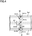
- the alignment marks positioned on an upper side (as seen in FIG. 4 ) of the sheet-like base material Sw and of the sheet-like mask material Sm are referred to as Am1u, Am2u, and the alignment marks positioned on a lower side thereof are referred to as Am1d, Am2d, respectively.
- the control means Cu analyses the captured images of the alignment marks Am1u, Am2u, Am1d, Am2d at the portion Sw1 of the sheet-like base material Sw and at the portion Sm1 of the sheet-like mask material Sm.
- Detection is then made of an amount of relative displacement ⁇ X in the X-axis direction, and at least one of amounts of relative displacement ⁇ Y in the Y-axis direction and angle ⁇ ⁇ z.
- the alignment marks Am1u and Am2u are captured by the imaging means 82 at the same time and image analysis is made to detect the positional differences in the X-axis direction and in the Y-axis direction, respectively
- the alignment marks Am1d and Am2d are captured by the imaging means 81 at the same time and image analysis is made to detect the positional differences in the X-axis direction and in the Y-axis direction, respectively.
- the control means Cu calculates the amount of change in the number of revolutions of the electric motor DM2 (i.e., amount of acceleration in speed or amount of deceleration in speed) based on the detected amount of relative change ( ⁇ X) and gives a command accordingly to correct the position, in the X-axis direction, of the sheet-like mask material Sm relative to the sheet-like base material Sw.
- a command is given of the amount of movement in the Y-axis direction of the Y - ⁇ z stage 5 based on the detected amount of relative displacement ( ⁇ Y).
- a command is given of the amount of rotation, about the Z-axis, of the Y- ⁇ z stage 5 based on the angle ( ⁇ ⁇ z) so as to correct the position of the sheet-like mask material Sm relative to the sheet-like base material Sw.
- control means Cu analyzes the images, as captured by the imaging means 83, of the clearance in the Z-axis direction between the sheet-like base material Sw and the sheet-like mask material Sm, and detects the relative amount of displacement ( ⁇ z), in the Z-axis direction, of the sheet-like mask material Sm relative to the sheet-like base material Sw. Based on the detected relative amount of displacement ( ⁇ z), a command is given of a vertical amount of movement of the linear actuators 6, thereby correcting the clearance (height position) between the sheet-like base material Sw and the sheet-like mask material Sm.
- the control means Cu After having corrected the traveling speed, position, and height position of the sheet-like mask material Sm relative to the sheet-like base material Sw, the control means Cu performs, whenever capturing is made, e.g., at predetermined intervals, of the alignment marks Am1, Am2 at the portion Sw1 of the sheet-like base material Sw and the portion Sm1 of the sheet-like mask material Sm, detecting is made of the amount of relative displacement ⁇ X, at least one of the amount of relative displacement ⁇ Y and the angle ⁇ ⁇ z, as well as the clearance between the sheet-like base material Sw and the sheet-like mask material Sm, respectively. Once the detected figures go outside the predetermined range, according to the above procedures, the position and the traveling speed of the sheet-like mask material Sm relative to the sheet-like base material Sw are corrected.
- each of the rollers 42a ⁇ 42d as the parallel travel region forming unit and the driving unit that causes the sheet-like mask material Sm to travel are disposed on a single rack 41 that causes the sheet-like mask material Sm to travel, is formed into a unit as a result of mounting on a single rack 41.
- the rack 41 In aligning the positions of the portion Sm1 of the sheet-like mask material Sm relative to the portion Sw1 of the sheet-like base material Sw1, the rack 41 itself is moved or rotated. It means that the traveling conditions of the sheet-like mask material Sm to which a predetermined tension has been applied does not change. The forceful strains do neither occur to the sheet-like mask material Sm and, as a consequence, to the mask pattern.
- the one in use may be replaced for a new one on which, e.g., a cleaned sheet-like mask material Sm has been set in position. In this manner, the film forming work can be started again soonest possible.
- the base material is thermally expanded by radiation heat at the time of evaporating the depositing material through resistance heating by a resistance board 91.
- the sheet-like base material Sw has been thermally expanded in the X-axis direction, even though control is made so as to cause the sheet-like base material Sw and the sheet-like mask material Sm by the same length (travel amount) per unit time as described above, the result will be that the sheet-like base material Sw delays relative to the sheet-like mask material Sm.
- the Y- ⁇ z stage 5 it is conceivable to arrange the Y- ⁇ z stage 5 to be movable also in the X-axis direction to enable the correction of the amount of relative displacement ⁇ X accompanied by the thermal expansion.
- correction can be made to the relative amount of displacement ⁇ X only within a range of amount of traveling of the Y- ⁇ z stage 5 in the X-axis direction. If the delay in the sheet-like base material Sw is accumulated because of a very large length of the sheet-like base material Sw to be processed, there will arise a case in which the position of the sheet-like mask material Sn relative to the sheet-like base material Sw can no longer be corrected.
- the variation of the number of rotation of the electric motor DM2 i.e., the amount of acceleration or the amount of deceleration
- ⁇ X the detected amount of relative displacement
- the relative amount of displacement of ⁇ X is added to, or subtracted from, the amount of traveling when the sheet-like base material Sw and the sheet-like mask material Sm are caused to travel in the same amount of traveling per unit time. Therefore, the delay that may happen to the sheet-like base material Sw due to thermal expansion in the X-axis direction can also be corrected. In addition, even in case the sheet-like base material Sw is very long, correction can be made perpetually.
- the film forming means may alternatively be arranged to be a sputtering cathode, or CVD method as a means for supplying raw gas for forming a thin film of a predetermined thickness.
- the downstream guide roller 23 is provided with the sensor 25 as a speed detecting means and in which, according to the detected values of the sensor 25, control is made such that the feed speed of the sheet-like base material Sw becomes equal to the feed speed of the sheet-like mask material Sm.
- an arrangement may alternatively be made such that, e.g., the feed speed of the sheet-like mask material Sm is detected and that the electric motor DM1 is controlled according to the detected values so that the feed speed Sw of the sheet-like base material Sw can be corrected.
- the number of rotation of the electric motor DM2 is increased or decreased, thereby correcting the position of the sheet-like mask material Sm relative to the sheet-like base material Sw so that both the alignment marks Am1, Am2 vertically overlap each other in the Z-axis direction.
- a can roller Cr is disposed on an upper side of the sheet-like base material Sw.
- the can roller Cr is provided with a linear actuator (not illustrated) so as to be vertically movable in the Z-axis direction.
- two pressing rollers R1, R2 are disposed on an upper side of the sheet-like base material Sw at a predetermined distance from each other in the X-axis direction in a manner to lie opposite to the box 92 in which the resistance board 91 is housed.
- Each of the pressing rollers R1, R2 is provided with a linear actuator (not illustrated) so that each of the rollers R1, R2 is vertically movable in the Z-axis direction in a manner interlocked with each other.
- a direct-acting actuator 6 that is disposed in the Y- ⁇ z stage 5 causes each of the rollers 42a ⁇ 42d to vertically move integrally in the Z-axis direction so as to correct the clearance in the Z-axis direction.
- a tilting means 60 is further provided for tilting the portion Sm1 of the sheet-like mask material Sm relative to the portion Sw1 of the sheet-like base material Sw which travel in parallel with each other.
- a mask material traveling means 40 there are provided, at a predetermined distance from each other, three linear actuators 60 on the Y- ⁇ z stage 5 in a manner to be vertically movable in the Z-axis direction.
- Each of the linear actuators 60 has respectively connected thereto an operation rod 62 through free (spherical) joint 61.
- a frame 64 to rotatably support each of the rollers 42a ⁇ 42d is supported.
- each of the linear actuators 60, joints 61 and supporting rods 62 constitute the tilting means in this embodiment.
- Such a side wall surface in the Y-axis direction as will define the film forming chamber 1a is provided with a third detecting means.
- three imaging means 83a ⁇ 83c such as CCD cameras and the like are disposed in the X-axis direction at an equal distance from each other. It is thus so arranged that, in the region in which the sheet-like base material Sw and the portion of the sheet-like mask material Sm are in a vertical positional relationship with each other, the images of the sheet-like base material Sw and the sheet-like mask material Sm can be captured in a plurality of positions.
- the control means Cu detects the tilting of the sheet-like mask material Sm relative to the sheet-like base material Sw based on the clearance in the Z-axis direction between the portions Sw1 of the sheet-like base material Sw and the portions Sm1 of the sheet-like mask material Sm, as detected by each of the imaging means 83a ⁇ 83c. Based on the detected tilting, the amount of the above-mentioned tilting of the sheet-like mask material Sm relative to the sheet-like mask material Sm is commanded to the linear actuator 60 as the tilting means, thereby correcting the above-mentioned tilting.
- the alignment marks Am1, Am2 will be deviated at least in one direction of the X-axis direction and the Y-axis direction. Therefore, after the above-mentioned correction to the tilting, corrections will be made, according to the above-mentioned procedures, of the traveling speed and the position of the sheet-like mask material Sm relative to the sheet-like base material Sw.
- the images captured by the imaging means 81, 82 are analyzed to respectively detect the amount of relative displacement value ⁇ X in the X-axis direction, and at least one of the amount of relative displacement ⁇ Y in the Y-axis direction and the angle ⁇ ⁇ z. Thereafter, based on the clearance in the Z-axis direction as respectively detected by the imaging means 83a ⁇ 83c as the third detection means, tilting of the sheet-like mask material Sm relative to the sheet-like base material Sw is detected.
- the amount of tilting of the sheet-like mask material Sm relative to the sheet-like base material Sw is commanded to the linear actuators 60 as the tilting means, thereby correcting the above-mentioned tilting.
- the control means Cu calculates errors of movement, accompanied by the tilting correction, in the X-axis direction and in the Y-axis direction of the sheet-like mask material Sm relative to the sheet-like base material Sw.
- the error of movement is calculated out into at least one of the amount of relative displacement ⁇ X, the amount of relative displacement ⁇ Y in the Y-axis direction and the angle ⁇ ⁇ z.
- the amount of movement in the vertical direction of the linear actuator 6 is commanded, thereby correcting the clearance (height position) between the sheet-like base material Sw and the sheet-like mask material Sm.
Landscapes
- Chemical & Material Sciences (AREA)
- Chemical Kinetics & Catalysis (AREA)
- Engineering & Computer Science (AREA)
- Materials Engineering (AREA)
- Mechanical Engineering (AREA)
- Metallurgy (AREA)
- Organic Chemistry (AREA)
- Physical Vapour Deposition (AREA)
- Details Or Accessories Of Spraying Plant Or Apparatus (AREA)
Abstract
Description
- The present invention relates to a film forming apparatus and a film forming method and, in particular, to an arrangement in which, while a sheet-like (or sheet-shaped) base material is caused to travel at a predetermined speed, a film forming material is fed beyond a mask so as to form a film in succession on one surface of the base material in a predetermined pattern.
- This kind of film forming apparatus is known, for example, in
Patent Document 1. The apparatus in question is provided with: a base material traveling means for causing a sheet-like (or band-like) base material to travel; a transcription substrate traveling means for causing a sheet-like transcription substrate to travel in an annular form; a film forming means for feeding a film forming material to a portion of the sheet-like transcription substrate; and a mask material traveling means for causing the sheet-like mask material (shadow mask) to travel in synchronization with the transcription substrate in partially close contact therewith, the mask material serving to limit the scope of supplying the film forming material to the transcription substrate. Then, by feeding the film forming material beyond the mask to the transcription substrate, what has been formed into a film of a predetermined pattern on one surface of the sheet-like transcription substrate is transcribed to the sheet-like substrate. In this manner, a predetermined film is formed continuously in a predetermined pattern on one surface of the sheet-like base material. According to this example, after having formed a predetermined film on the transcription substrate beyond the mask, the predetermined film is then transcribed to the sheet-like base material. Therefore, by the amount of increase in the processing steps the apparatus itself will become larger in size and more complicated. Not only is the cost of the apparatus higher but also, due to the necessity of the transcription substrate, is the manufacturing cost higher. - By the way, in the above-mentioned prior art example, the portion of the sheet-like substrate and the portion of the sheet-like transcription substrate are positioned in parallel with each other in a vertical positional relationship with each other. In the transcription region inclusive of the part where transcription to the sheet-like base material is to take place, there is provided a gap between both the portions. Therefore, in order to perform alignment of the transcription substrate relative to the portion of the base material, there is provided an alignment mechanism. In this case, the alignment mechanism performs alignment of the transcription substrate relative to the base material by adjusting a widthwise position and angle of a pair of guide rolls that are disposed in a manner to pinch the transcription portion. However, in this kind of method, the tension to be applied to the sheet-like transcription substrate or to the sheet-like mask material becomes non-uniform, thereby giving rise to the occurrence of strains to the sheet-like transcription substrate and the sheet-like mask material. Therefore, there is a possibility that alignment cannot be made at a higher accuracy.
-
- Patent Document 1:
-
JP 2003-173870 A - In view of the above points, this invention has a problem of providing a film forming apparatus and a film forming method in which, when a film is formed continuously in a predetermined pattern on one surface of the base material by feeding the film forming material beyond the mask while the sheet-like base material is caused to travel at a predetermined speed, the portion of the sheet-like base material and the portion of the sheet-like transcription substrate can be aligned with each other at a high accuracy, and also the apparatus cost and the running cost can be reduced.
- In order to solve the above-described problems, the film forming apparatus according to this invention has, inside a vacuum processing chamber: a base material traveling means for causing a sheet-like base material to travel at a predetermined speed; a film forming means for feeding a film forming material to a portion of the sheet-like base material which travels in one direction; and a mask material traveling means for causing to travel a sheet-like mask material which limits a scope of feeding of the film forming material to the sheet-like base material. On condition that a direction from the film forming means toward the sheet-like base material is defined to be upper side, the mask material traveling means comprises: a parallel travel region forming unit which causes such a portion of the sheet-like mask material as is positioned on a lower side of the sheet-like base material that travels in one direction, to travel in parallel with the sheet-like base material; and a driving unit which causes the sheet-like mask material to travel in synchronization with the sheet-like base material. The parallel travel region forming unit and the driving unit are disposed on a single rack.
- According to this invention, while causing the portion of the sheet-like mask material to travel in parallel with such a portion of the sheet-like base material as is caused to travel in one direction, the film forming material is directly fed from a film forming source, thereby forming a film beyond the sheet-like mask material. Therefore, unlike the above-mentioned conventional example, the mechanism and the like for once transcribing to another base material becomes unnecessary. It is therefore possible to reduce the cost for the apparatus as well as the cost for running the apparatus. In addition, the elements for causing the sheet-like mask material to travel are mounted on a single rack into a unit. In this manner, an arrangement has been employed in which the rack itself is moved so that the portion of the sheet-like mask material is aligned with the portion of the sheet-like base material. At the time of aligning the portion of the sheet-like mask material with the portion of the sheet-like base material, the traveling state of the sheet-like mask material to which a certain tension has been applied, will not vary. Therefore, the sheet-like mask material and, in turn, its mask pattern will never give rise to a forced strain. As a result, the portion of the sheet-like base material and the sheet-like mask material can be subjected to continuous film forming on the sheet-like base material in an accurate pattern in a state in which the portion of the sheet-like base material and the sheet-like mask material are aligned with each other at a high accuracy. By the way, preferably, the elements for causing the sheet-like mask material to travel, as described above, shall be disposed on the single rack so as to make them into a unit. And the unit in which the sheet-like mask material is set in position in advantage shall preferably be prepared in a plurality of numbers in advance. By making such an arrangement, in case the one in use must be subjected to maintenance (e.g., replacement, cleaning, and the like of the sheet-like mask material), another unit in which, e.g., an already cleaned sheet-like mask material is set in position can be set into the film forming apparatus. In this manner, film forming on the sheet-like base material can be started again at the shortest waiting time.
- In this invention, the film forming apparatus preferably further comprises: a speed detecting means for detecting a speed at which the sheet-like base material or the sheet-like mask material is caused to travel; on condition that a direction in which the portion of the sheet-like base material is caused to travel in one direction is defined to be an X-axis direction, a first detecting means for detecting an amount of relative displacement, in the X-axis direction, of the sheet-like mask material relative to the sheet-like base material in a region in which the portion of the sheet-like base material and the portion of the sheet-like mask material are positioned in a vertical positional relationship with each other. The film forming apparatus is arranged such that: one of the sheet-like base material and the sheet-like mask material is made to coincide with a detected value, by the speed detecting means, of the other of the sheet-like base material and the sheet-like mask material, thereby synchronizing the sheet-like base material and the sheet-like mask material with each other and that: one of the base material traveling means and the driving unit is controlled depending on the detected value by the first detecting means, thereby correcting the position of the sheet-like mask material relative to the sheet-like base material.
- Further, in this invention, on condition that a direction in which the portion of the sheet-like base material is caused to travel in one direction is defined to be an X-axis direction, that the direction crossing the X-axis direction at right angles is defined to be Y-axis direction, and that a direction of rotation about a Z-axis as a vertical direction is defined to be Θz direction, the rack is disposed on a Y-Θz stage. The apparatus preferably further comprises: a second detecting means for detecting, in a region in which the portion of the sheet-like base material and the portion of the sheet-like mask material are positioned in a vertical positional relationship with each other, a relative amount of displacement in the Y-axis direction of the sheet-like mask material relative to the sheet-like base material, or an angle to be formed by the traveling direction of the sheet-like base material and the traveling direction of the sheet-like mask material. Depending on a detected value by the second detecting means, at least one of movement in the Y-axis direction of, and rotation about the Θ direction of, the rack is performed by the Y-Θz stage, thereby correcting the position of the sheet-like mask material relative to the sheet-like base material.
- Further, in this invention, in case the mask material traveling means causes to parallelly travel the portion of the sheet-like mask material at a predetermined vertical clearance to the portion of the sheet-like base material that is caused to travel in said one direction, the Y-Θz stage preferably comprises: a driving means for vertically moving the Y-Θz stage; a third detecting means for detecting a vertical clearance between the sheet-like base material and the sheet-like mask material in the region in which the portion of the sheet-like base material and the portion of the sheet-like mask material are positioned in a vertical positional relationship with each other. Depending on a detected value by the third detecting means, the Y-Θz stage is vertically moved by the driving means, thereby correcting the height position of the sheet-like mask material relative to the sheet-like base material.
- On the other hand, the film forming apparatus may be arranged to comprise an urging means for urging, in an upper region of the film forming means, the portion of the sheet-like base material toward the portion of the sheet-like mask material so as to bring the sheet-like base material into contact with the sheet-like mask material.
- By the way, in this invention, in view of the ease of performing maintenance and the like, preferably the film forming apparatus further comprises a moving means for allowing the mask material traveling means to be movable in the Y-axis direction between inside the vacuum processing chamber and outside the vacuum processing chamber.
- Further, in order to solve the above-mentioned problems, the film forming method of this invention in which a film is formed forming a film on a sheet-like base material by using the above-mentioned film forming apparatus comprises: on condition that alignment marks respectively disposed on the sheet-like base material and on the sheet-like mask material at a predetermined interval from one another in the X-axis direction, the first detecting means and the second detecting means are defined to be imaging means respectively: capturing with the imaging means the alignment marks in the portion of the sheet-like base material and in the portion of the sheet-like mask material, and analyzing the captured images, thereby detecting: a relative amount of displacement (ΔX) in the X-axis direction of the sheet-like mask material relative to the sheet-like base material; and at least one of a relative amount of displacement (Δ Y) in the Y-axis direction of the sheet-like mask material relative to the sheet-like base material, and an angle (Δ Θz) formed by a traveling direction of the sheet-like base material and a traveling direction of the sheet-like mask material. The method comprises: based on the detected relative amount of displacement (ΔX), giving a command of an amount of change in the traveling speed of the sheet-like base material or of the sheet-like mask material to one of the base material traveling means and the driving unit and; in synchronization therewith, based on at least one of the detected relative amount of displacement (ΔY) and the angle (ΔΘz), giving a command, to the Y - Θz stage, of a movement amount of at least one of the movement in the Y-axis direction and rotation in the Θ direction of the rack, thereby correcting the traveling speed and the position of the sheet-like mask material relative to the sheet-like base material.
- According to this arrangement, in a state in which the portion of the sheet-like base material and the portion of the sheet-like mask material are aligned with each other at a high accuracy, the film forming material can be fed beyond the mask to the sheet-like base material that is caused to travel at a predetermined speed, whereby a film can be formed continuously in a predetermined pattern on one surface of the base material.
- By the way, in case the portion of the sheet-like mask material is caused to travel in parallel with the portion of the sheet-like base material which is caused to travel in parallel with the portion of the sheet-like base material that is caused to travel in one direction by the mask material traveling means while keeping a predetermined vertical clearance therebetween, thereby performing film forming in the region in question, should the portion of the sheet-like mask material be tilted slightly relative to the portion of the sheet-like base material, thereby giving rise to a relatively large clearance between the two, blurs attributable to the mask conditions will occur in the region concerned and film forming cannot be performed at a high accuracy.
- According to this invention, in case the mask material traveling means further comprises: a tilting means for tilting the portion of the sheet-like mask material relative to the sheet-like base material, both said materials being arranged to travel in parallel with each other, the third detecting means being disposed in the X-axis direction in a plurality of numbers at a predetermined distance from one another. The method preferably comprises: detecting tilts of the sheet-like mask material relative to the sheet-like base material from a distance, as respectively detected by the third detecting means, in the Z-axis direction between the portion of the sheet-like base material and the portion of the sheet-like mask material; giving a command of an amount of tilting of the sheet-like mask material to the tilting means based on the detected tilts, thereby correcting the tilts and, after correcting the tilts, correcting the traveling speed and the position. According to this arrangement, it is possible to perform film forming on one surface of the sheet-like base material in a predetermined pattern in succession at a high accuracy without giving rise to blurs attributable to the mask conditions.
- On the other hand, the method may further comprise: analyzing the images captured by the imaging means to respectively detect a relative amount of displacement (ΔX) in the X-axis direction, and at least one of a relative amount of displacement (ΔY) in the Y-axis direction and an angle (ΔΘz); thereafter detecting tilts of the sheet-like mask material relative to the sheet-like base material from the distance in the Z-axis direction between the portion of the sheet-like base material and the portion of the sheet-like mask material as respectively detected by the third detecting means; correcting the tilts based on the detected tilts by commanding to the tilting means the amount of tilting of the sheet-like mask material relative to the sheet-like base material, and calculating an error of movement in the X-axis direction and in the Y-axis direction of the sheet-like mask material relative to the sheet-like base material accompanied by the correction of the tilts; commanding to one of the base material traveling means and the driving unit an amount of change in traveling speed of the sheet-like base material or the sheet-like mask material by adding the error of movement to the relative amount of displacement (ΔX), and at least one of the relative amount of displacement (ΔY) in the Y-axis direction and the angle (ΔΘz); and in synchronization therewith, commanding the amount of movement of at least one of the movement in the Y-axis direction of, and the rotation in the Θ direction of, the rack, thereby correcting the traveling speed of, and the position of, the sheet-like mask material relative to the sheet-like base material. According to this arrangement, the position of the sheet-like mask material relative to the sheet-like base material can advantageously be corrected soonest possible.
-
-
FIG. 1 is a schematic perspective view showing an arrangement of a film forming apparatus according to an embodiment of this invention. -
FIG. 2 is a schematic sectional view showing the film forming apparatus shown inFIG. 1 . -
FIG. 3(a) and FIG. 3(b) are figures explaining the positional displacements of a sheet-like base material relative to a sheet-like mask material. -
FIG. 4 is a figure explaining the aligning of the sheet-like base material relative to the sheet-like mask material. -
FIG. 5 is a sectional view showing in enlargement an essential portion of the film forming apparatus relating to a modified embodiment of this invention. -
FIG. 6 is a sectional view showing in enlargement an essential portion of the film forming apparatus relating to another modified embodiment of this invention. -
FIG. 7(a) and FIG. 7(b) are a front view and a side view, respectively, showing in enlargement an essential portion of the film forming apparatus relating to still another modified embodiment of this invention. - With reference to the drawings, a description will be made hereinbelow of an embodiment of a film forming apparatus according to this invention in which a film forming means is made to serve as a resistance board and in which, while a sheet-like base material Sw is caused to travel at a given speed, a predetermined thin film is continuously formed beyond a mask Sm. In the following description the direction in which a portion Sw1 of the sheet-like base material Sw is caused to be transferred in one direction inside a
film forming chamber 1a is defined to be X-axis direction (i.e., the right-and-left direction inFIG. 2 ), the direction crossing this X-axis direction on one and the same plane is defined to be Y-axis direction, the direction crossing at right angles both the X-axis direction and the Y-axis direction is defined to be Z-axis direction (i.e., the up-and-down or vertical direction inFIG. 2 ), and the direction of rotation about the Z-axis is defined to be Θz direction. Further, the terms denoting the directions such as up, down, left and right shall be based onFIG. 2 . - With reference to
FIGS. 1 and2 , a reference sign DM denotes a film forming apparatus according to an embodiment of this invention. The film forming apparatus DM is provided with avacuum processing chamber 1 which is connected to a vacuum pump (not illustrated) and is evacuated to a predetermined pressure. Thevacuum processing chamber 1 is constituted by afilm forming chamber 1a which performs film forming processing relative to a sheet-like base material Sw, an upstream-sideauxiliary chamber 1b, and a downstream-sideauxiliary chamber 1c, the auxiliary chambers being disposed on the left side and right side, respectively, as seen in the X-axis direction of the film-formingchamber 1a. - The upstream-side
auxiliary chamber 1b is provided with: afeed roller 21 which holds the sheet-like base material Sw in a round-around state and which is driven to rotate by an electric motor DM1, and an upstream-side guide roller 22 and a downstream-side guide roller 23 which wind around the sheet-like base material Sw fed out of thefeed roller 21 to thereby guide the sheet-like base material to an upper space of thefilm forming chamber 1a. Inside the upstream-sideauxiliary chamber 1b there is further disposed adancer roller 24 which is movable in the Z-axis direction, the dancer roller being positioned between the upstream-side guide roller 22 and the downstream-side guide roller 24. Thedancer roller 24 is provided on itsrotary shaft 24a with aspring 24b which urges therotary shaft 24a upward. It is thus so arranged that the tension of the sheet-like base material Sw that passes through the film forming chamberla can be maintained at a predetermined value. It is to be noted that the arrangement to maintain the tension of the sheet-like base material Sw at the predetermined value shall not be limited to the one described above. Instead, by means of the conventional actuator the tension of the sheet-like base material Sw may be arranged to be variable. Further, the downstream-side guide roller 23 is provided with asensor 25 as a means for detecting the rotational speed of the downstream-side guide roller 23. It is thus so arranged that, based on the rotational speed, the feed speed of the sheet-like base material Sw into thefilm forming chamber 1a can be detected by the rotational speed. - The downstream-side
auxiliary chamber 1c is provided with: a take uproller 31 which takes up and recover the sheet-like base material Sw that has been subjected to the processing of thin film forming through thefilm forming chamber 1a; and aguide roller 32 which guides the sheet-like base material Sw from thefilm forming chamber 1a to the take uproller 31. Then, by means of the downstream-side guide roller 23 inside the upstream-sideauxiliary chamber 1b and by means of theguide roller 32 inside the downstream-sideauxiliary chamber 1c, the sheet-like base material Sw is transferred along the upper space of thefilm forming chamber 1a horizontally in the X-axis direction and, as a consequence, the lower surface thereof becomes the surface to which the film is formed. In this embodiment each of the above-mentionedelements 21 ∼ 24 and 31, 32 constitute the base material traveling means which cause the sheet-like base material Sw to travel at a predetermined speed. - In the
film forming chamber 1a there is provided a sheet-like mask material traveling means 4 for causing to travel the sheet-like mask material Sm which limits the scope of supply of the film forming material to the sheet-like base material Sw relative to the portion Sw1 of the sheet-like base material Sw to be transferred inside thefilm forming chamber 1a. The mask material traveling means 4 is constituted by asingle rack 41 that is made up of arectangular substrate portion 41a and four plate-like supportingportions 41b which are vertically disposed respectively at the four corners of thesubstrate portions 41a. On those surfaces of the supportingportions 41b of therack 41 which lie opposite to each other in the Y-axis direction, tworollers 42a∼42d are respectively rotatably supported at a predetermined clearance therebetween in the vertical direction. A rotary shaft of theroller 42d that is positioned on the left lower side is connected to an electric motor DM2. In this arrangement, a sheet-like mask material Sm is endlessly wound around each of therollers 42a∼42d and, by means of rotating drive by the motor DM2, the sheet-like mask material Sm travels. In this embodiment, the left-upper-side roller 42a and the right-upper-side roller 42b that are disposed in the X-axis direction at a distance from each other constitute a parallel travel region forming unit which causes that portion Sm1 of the sheet-like base material Sm to travel horizontally at a predetermined vertical clearance relative to that portion Sw1 of the base material Sw which is horizontally transferred inside thefilm forming chamber 1a. Theroller 42d which is positioned on the left lower side and is provided with the electric motor DM2 constitute a driving unit which causes the sheet-like mask material Sm to travel in synchronization with the sheet-like base material Sw. - In concrete, based on the feed speed of the sheet-like base material Sw depending on the detected value by the
sensor 25, the rotational speed of the motor DM2 is computed. Control is then made such that the feed speed of the sheet-like base material Sw becomes equivalent to the feed speed of the sheet-like mask material Sm. As the sheet-like mask material Sm, there is used one in which are formed openings or slits as mask patterns depending on the patterns to be formed on the sheet-like base material Sw. Further, on both ends of the width direction (Y-axis direction) of the sheet-like base material Sw and the sheet-like mask material Sm, there are formed, at a predetermined spacing (e.g., within a range of 5∼10 mm) in the Y-axis direction on the same X-axial line, alignment marks Am1, Am2 for detecting the amounts of relative displacement ΔX, ΔY and Δ Θz relative to the sheet-like base material Sw (seeFIG. 3 ). The alignment mark Am1 of the sheet-like base material Sw may be constituted, e.g., by a perforated hole which is circular as seen in plan view (i.e., as seen from top downward), and the alignment mark Am2 of the sheet-like mask material Sw may be constituted, e.g., by a perforated hole and the like which is smaller in diameter than the alignment mark Am1. Alignment is made, for example, such that the centers of both the alignment marks Am1, Am2 coincide with each other. Further, for the purpose of controlling and the like of the film forming processing with respect to the sheet-like base material Sw, both ends of the width direction (Y-axis direction) of the sheet-like base material Sw have formed therein marks Sp, Ep which indicate the point of starting detection and the point of ending detection, as distinguished from the alignment marks Am1, Am2. In this case the marks Sp, Ep can be formed of perforated holes which are larger in diameter than the alignment marks Am1, Am2 or may be formed in perforated triangles as seen in plan view. The alignment marks Am1, Am2 may be formed only in one end in the width direction (Y-axis direction) of the sheet-like base material Sw and the sheet-like mask material Sm so that the sheet-like mask material Sm can be aligned relative to the sheet-like base material Sw. - In addition, the
film forming chamber 1a is provided with a Y-Θz stage 5 which supports therack 41. On the Y-Θz stage 5 there are providedlinear actuators 6 which are movable in the vertical direction. As the Y-Θz stage 5, since there may be utilized one having the known construction that can perform the movement of therack 41 in the Y-axis direction, and the one that can perform the rotation of therack 41 in the Θz direction, and as thelinear actuator 6, there may be utilized one having the known construction that can vertically move theentire rack 41 together with the Y-Θz stage. Therefore, detailed explanations thereabout are omitted here. Still furthermore, on the lower surface of thefilm forming chamber 1a there aredisposed rail members 71 which extend in the Y-axis direction. Acart 72 that can travel along therail members 71 is disposed. On thecart 72 there are disposed the Y-Θz stage 5 and therack 41 through thelinear actuators 6. In this case, doors that can be opened and closed (not illustrated) are disposed on wall surfaces that define thefilm forming chamber 1a so that the mask material traveling means 4 can be moved into and out of thefilm forming chamber 1a. In this embodiment therail members 71 and thecart 72 constitute the moving means which causes the mask material traveling means 4 to be movable inside thefilm forming chamber 1a and outside thefilm forming chamber 1a in the Y-axis direction. - Further, on an upper wall surface 11 that defines the
film forming chamber 1a, there are disposed twopeep holes 12 at a predetermined distance from each other in the Y-axis direction. Above the peep holes 12 there are disposed imaging means 81, 82 such as CCD cameras and the like. In this case, the imaging means 81, 82 are arranged to capture, on both widthwise (Y-axis direction) ends of the sheet-like base material Sw, the relative position of the portion Sm1 or alignment marks Am1, Am2 of the sheet-like mask material Sm relative to the portion Sw1 of the sheet-like base material Sw1 that is transferred horizontally inside thefilm forming chamber 1a. In this embodiment, both the imaging means 81, 82 constitute a second detecting means for detecting: an amount of relative displacement ΔY in the Y-axis direction of the sheet-like mask material Sm relative to the sheet-like base material Sm; or an angle Δ Θz to be formed by the traveling direction of the sheet-like base material Sw and the traveling direction of the sheet-like mask material Sm. At the same time, both the imaging means 81, 82 serve a dual function as a first detecting means for detecting, in a region Sw1 in which the portion of the sheet-like base material Sm1 and the portion of the sheet-like mask material Sw are in a vertical positional relationship with each other, the amount of relative displacement ΔX in the X-axis direction of the sheet-like mask material Sm relative to the sheet-like base material Sw. Then, the images captured by the imaging means 81, 82 are analyzed by the known image analyzing means, and depending on the analyzed values (detected values), the Y-Θz stage 5 is appropriately moved or rotated, whereby the position of the sheet-like mask material Sm relative to the sheet-like base material Sw is corrected. - In concrete, as exemplified in
FIG. 3(a) , in case the sheet-like mask material Sm is deviated to one side in the Y-axis direction relative to the sheet-like base material Sw1, the images captured by the imaging means 81, 82 are analyzed by the known image analyzing means to obtain an amount of displacement ΔY. Depending on the amount of displacement, the Y-Θz stage 5 is moved in one Y-axis direction for correction. On the other hand, as exemplified inFIG. 3(b) , in case the sheet-like mask material Sm is snaking relative to the sheet-like base material Sw, the images captured by the imaging means 81, 82 are analyzed by the known image analyzing means. In this manner, the angle Δ Θz to be formed by the traveling direction of the sheet-like base material Sw and the traveling direction of the sheet-like mask material Sm (i.e., the tilting of the sheet-like mask material Sm relative to the sheet-like base material Sw on the X-Y plane) is computed. Depending on the angle, by appropriately moving the Y-Θz stage 5 in the Θz-axis direction, the Y-Θz stage 5 is rotated about the Z-axis for correction. In addition, the images captured by the imaging means 81, 82 are similarly analyzed and, depending on the analyzed values (detected values), the number of rotation of the electric motor DM1 or DM2 is increased or decreased. The positions of the sheet-like mask material Sm is corrected relative to the sheet like base material Sw so that both the alignment marks Am1, Am2 vertically overlap each other in the Z-axis direction. The sheet-like base material Sw and the sheet-like mask material Sm are caused to travel in synchronization with each other. - On the side wall surface, in the Y-axis direction, which defines the
film forming chamber 1a, there is also provided a peep hole (not illustrated). On a side of the peep hole there is disposed an imaging means 83 such as CCD cameras and the like. In this embodiment, the imaging means 83 constitutes a third detecting means which detects the vertical clearance between the sheet-like base material Sw and the sheet-like mask material Sm in a region in which the portion Sw1 of the sheet-like base material Sw and the portion Sm1 of the sheet-like mask material Sm are positioned in a vertical positional relationship with each other. And the images captured by the imaging means 83 are analyzed by the known image analyzing means. Depending on the analyzed value (detected value), thelinear actuators 6 are appropriately moved vertically to thereby correct the height position of the sheet-like mask material Sm relative to the sheet-like base material Sw. The following control and the like may be performed any time during the film forming operation, i.e.: the control of coinciding the feed speed of the sheet-like base material Sw and the feed speed of the sheet-like mask material Sm; correction of the relative position in the X-axis direction and in the Y-axis direction of the portion Sm1 of the sheet-like base material Sw relative to the portion Sw1 of the sheet-like base material Sw to be horizontally transferred inside thefilm forming chamber 1a; and the correction of the clearance in the vertical direction between the sheet-like base material Sw and the sheet-like mask material Sm. According to this arrangement, the sheet-like mask material Sm can be aligned at high accuracy with the sheet-like mask material Sm, and highly accurate film forming can be performed. Also, blurs due to too large a clearance in the vertical direction can be prevented from occurring to the thin film formed on the base material Sw. - The
film forming chamber 1a has disposed therein a film forming means 9 below the portion Sm1 of the sheet-like mask material Sm in a space inside the supportingportion 41b of therack 41. The film forming means 9 contains therein a film forming material (not illustrated) to be subjected to selection depending on the composition of the thin film to be formed on the sheet-like base material Sw, and is provided with aresistance board 91 for evaporating the film forming material by electric resistance heating, and abox 92 for storing therein theresistance board 91. Thefilm forming means 9 is supported by such side wall surfaces in the Y-axis direction as define thefilm forming chamber 1a. In this case, thebox 92 may also be so constituted as to be pushed into, or pulled out of, thefilm forming chamber 1a, thereby facilitating the supplementing of the evaporating material or the maintenance of thebox 92. Alternatively, a plurality ofboxes 92 having therein set in advance the film forming material on theresistance board 91 may be prepared in a plurality of numbers so that, in case thebox 92 now in use need be subjected to maintenance, anotherbox 92 may be set in position instead, thereby facilitating the starting again of film forming on the sheet-like base material Sw as soon as possible. - The above-mentioned film forming apparatus DM is provided with a control means Cu which is made up of a personal computer, sequencer, and the like for controlling overall operations of the apparatus. The control means Cu performs: synchronized traveling of the sheet-like base material Sw and the sheet-like mask material Sm; calculation of amounts of correction based on the input of image data captured by the imaging means 81, 82, 83; correction of positions, by the Y-
Θz stage 5, of the sheet-like mask material Sm relative to the sheet-like base material Sw; and the like. A description will now be made, with reference toFIG. 4 , of an example of a method of film forming by using the above-mentioned film forming apparatus DM. - In the upstream-side
auxiliary chamber 1b the sheet-like base material Sw is held by thefeed roller 21. The front end of the sheet-like base material Sw is caused to pass, via an upstream-side guide roller 22, the downstream-side guide roller 23 and thedancer roller 24, through the space in an upper portion of thefilm forming chamber 1a in which the mask material traveling means 4 has been set in position in advance, and is then wound around the take uproller 31 via aguide roller 32. At this time, the sheet-like mask material Sm is moved manually or in a similar manner so that the alignment marks Am1, Am2 are substantially in agreement with each other as seen in the Z-axis direction. Then, when thefilm forming chamber 1a, the upstream-sideauxiliary chamber 1b and the downstream-sideauxiliary chamber 1c have been evacuated to a predetermined pressure, the electric motors DM1, DM2 are driven for rotation. The sheet-like base material Sw from thefeed roller 21 is thus caused to travel and also in synchronization with the sheet-like base material, the sheet-like mask material Sm is caused to travel. At this time, from the feed speed of the sheet-like base material Sw depending on the values as detected by thesensor 25, the rotational speed of the electric motor DM2 is calculated. Control is then made such that the feed speed of the sheet-like base material Sw becomes equal to the feed speed of the sheet-like mask material Sm. The sheet-like base material Sw and the sheet-like mask material Sm are thus caused to travel by the same length per unit time (travel amount). - Now, the alignment marks positioned on an upper side (as seen in
FIG. 4 ) of the sheet-like base material Sw and of the sheet-like mask material Sm are referred to as Am1u, Am2u, and the alignment marks positioned on a lower side thereof are referred to as Am1d, Am2d, respectively. When a mark of the detection starting point Sp is captured by the imaging means 82, the control means Cu then analyses the captured images of the alignment marks Am1u, Am2u, Am1d, Am2d at the portion Sw1 of the sheet-like base material Sw and at the portion Sm1 of the sheet-like mask material Sm. Detection is then made of an amount of relative displacement ΔX in the X-axis direction, and at least one of amounts of relative displacement Δ Y in the Y-axis direction and angle Δ Θz. In concrete, as shown inFIG. 4 ,1 ) the alignment marks Am1u and Am2u are captured by the imaging means 82 at the same time and image analysis is made to detect the positional differences in the X-axis direction and in the Y-axis direction, respectively, and 2) the alignment marks Am1d and Am2d are captured by the imaging means 81 at the same time and image analysis is made to detect the positional differences in the X-axis direction and in the Y-axis direction, respectively. Then, average values of the positional differences in the X-axis direction and in the Y-axis direction as detected under items 1) and 2) are respectively calculated to thereby obtain relative amounts of displacement ΔX and ΔY at a middle point Am1c between both the alignment marks Am1u, Am1d of the sheet-like base material Sw, and at a middle point Am2c of both the alignment marks Am2u, Am2d of the sheet-like mask material Sm. On the other hand, in relation to the above-mentioned positional difference in the X-axis direction, a difference between the above-mentioned 1) and 2) is calculated. When the product is divided by the distance between the imaging means 81, 82, Δ Θz is calculated. Then, the control means Cu calculates the amount of change in the number of revolutions of the electric motor DM2 (i.e., amount of acceleration in speed or amount of deceleration in speed) based on the detected amount of relative change (ΔX) and gives a command accordingly to correct the position, in the X-axis direction, of the sheet-like mask material Sm relative to the sheet-like base material Sw. In addition, in case of a displacement, e.g., in the Y-axis direction, a command is given of the amount of movement in the Y-axis direction of the Y -Θz stage 5 based on the detected amount of relative displacement (ΔY). For example, in case a displacement has occurred, e.g., in the Θz direction, a command is given of the amount of rotation, about the Z-axis, of the Y-Θz stage 5 based on the angle (Δ Θz) so as to correct the position of the sheet-like mask material Sm relative to the sheet-like base material Sw. - In parallel with the above, the control means Cu analyzes the images, as captured by the imaging means 83, of the clearance in the Z-axis direction between the sheet-like base material Sw and the sheet-like mask material Sm, and detects the relative amount of displacement (Δ z), in the Z-axis direction, of the sheet-like mask material Sm relative to the sheet-like base material Sw. Based on the detected relative amount of displacement (Δ z), a command is given of a vertical amount of movement of the
linear actuators 6, thereby correcting the clearance (height position) between the sheet-like base material Sw and the sheet-like mask material Sm. - After having corrected the traveling speed, position, and height position of the sheet-like mask material Sm relative to the sheet-like base material Sw, the control means Cu performs, whenever capturing is made, e.g., at predetermined intervals, of the alignment marks Am1, Am2 at the portion Sw1 of the sheet-like base material Sw and the portion Sm1 of the sheet-like mask material Sm, detecting is made of the amount of relative displacement ΔX, at least one of the amount of relative displacement ΔY and the angle Δ Θz, as well as the clearance between the sheet-like base material Sw and the sheet-like mask material Sm, respectively. Once the detected figures go outside the predetermined range, according to the above procedures, the position and the traveling speed of the sheet-like mask material Sm relative to the sheet-like base material Sw are corrected.
- According to the above-mentioned embodiment, each of the
rollers 42a∼42d as the parallel travel region forming unit and the driving unit that causes the sheet-like mask material Sm to travel are disposed on asingle rack 41 that causes the sheet-like mask material Sm to travel, is formed into a unit as a result of mounting on asingle rack 41. In aligning the positions of the portion Sm1 of the sheet-like mask material Sm relative to the portion Sw1 of the sheet-like base material Sw1, therack 41 itself is moved or rotated. It means that the traveling conditions of the sheet-like mask material Sm to which a predetermined tension has been applied does not change. The forceful strains do neither occur to the sheet-like mask material Sm and, as a consequence, to the mask pattern. It follows that, in addition to the fact that the portion Sm1 of the sheet-like mask material Sm is caused to travel constantly in parallel with the portion Sw1 of the sheet-like base material Sw while keeping a predetermined vertical clearance, film forming can be performed on the sheet-like base material Sw with precise pattern. In addition, since therack 41 is disposed on the moving means 71, 72, when therack 41 is pulled out of thevacuum processing chamber 1 for carrying out maintenance and the like, such work can be carried out easily. By the way, an arrangement may alternatively be made that each of therollers 42a∼42d are disposed on asingle rack 41 into a unit, and a sheet-like mask material Sm set in position in advance may be prepared in a plurality of numbers. In case necessity arises that the one in use must be subjected to maintenance (replacement of the sheet-like mask material Sm, cleaning, and the like), the one in use may be replaced for a new one on which, e.g., a cleaned sheet-like mask material Sm has been set in position. In this manner, the film forming work can be started again soonest possible. - By the way, depending on the sheet-like base material Sw, there is a case in which the base material is thermally expanded by radiation heat at the time of evaporating the depositing material through resistance heating by a
resistance board 91. In case the sheet-like base material Sw has been thermally expanded in the X-axis direction, even though control is made so as to cause the sheet-like base material Sw and the sheet-like mask material Sm by the same length (travel amount) per unit time as described above, the result will be that the sheet-like base material Sw delays relative to the sheet-like mask material Sm. In this kind of case, it is conceivable to arrange the Y-Θz stage 5 to be movable also in the X-axis direction to enable the correction of the amount of relative displacement ΔX accompanied by the thermal expansion. However, according to this arrangement, correction can be made to the relative amount of displacement ΔX only within a range of amount of traveling of the Y-Θz stage 5 in the X-axis direction. If the delay in the sheet-like base material Sw is accumulated because of a very large length of the sheet-like base material Sw to be processed, there will arise a case in which the position of the sheet-like mask material Sn relative to the sheet-like base material Sw can no longer be corrected. On the other hand, according to the above-mentioned embodiment, the variation of the number of rotation of the electric motor DM2 (i.e., the amount of acceleration or the amount of deceleration) is calculated based on the detected amount of relative displacement (ΔX), and a command is given. The relative amount of displacement of ΔX is added to, or subtracted from, the amount of traveling when the sheet-like base material Sw and the sheet-like mask material Sm are caused to travel in the same amount of traveling per unit time. Therefore, the delay that may happen to the sheet-like base material Sw due to thermal expansion in the X-axis direction can also be corrected. In addition, even in case the sheet-like base material Sw is very long, correction can be made perpetually. Still furthermore, even in case the sheet-like base material Sw is very long, persistent correction is possible. Further, even in case the sheet-like base material Sw has been thermally expanded, the amount of displacement ΔY and the angle Θz have been calculated as described above, alignment can be made so as to minimize the effect of the thermal expansion of the sheet-like base material Sw. - A description has so far been made of the embodiment of this invention, but this invention shall not be limited to the above. In the above-mentioned embodiment, a description has been made of an example in which the elements from the mask material traveling means 4 to the
cart 72 are disposed inside thevacuum processing chamber 1. However, an arrangement may alternatively be made in which, e.g., only the mask material traveling means 4 and the Y-Θz stage 5 are disposed inside thevacuum chamber 1 so as to minimize the volume of thevacuum processing chamber 1. In addition, in the above-mentioned embodiment, a description has been made of an example in which the sheet-like mask material Sm is endlessly wound around each of therollers 42a∼42d. However, without being limited thereto, an arrangement may also be made so as to take up the sheet-like mask material from the feed roller to the take up shaft. - Further, in the above-mentioned embodiment, a description was made of an example in which vapor deposition is carried out by using the resistance board as the film forming means. Without being limited thereto, the film forming means may alternatively be arranged to be a sputtering cathode, or CVD method as a means for supplying raw gas for forming a thin film of a predetermined thickness. Furthermore, in the above-mentioned embodiment, a description was made of an example in which the
downstream guide roller 23 is provided with thesensor 25 as a speed detecting means and in which, according to the detected values of thesensor 25, control is made such that the feed speed of the sheet-like base material Sw becomes equal to the feed speed of the sheet-like mask material Sm. However, without being limited thereto, an arrangement may alternatively be made such that, e.g., the feed speed of the sheet-like mask material Sm is detected and that the electric motor DM1 is controlled according to the detected values so that the feed speed Sw of the sheet-like base material Sw can be corrected. In this case, the number of rotation of the electric motor DM2 is increased or decreased, thereby correcting the position of the sheet-like mask material Sm relative to the sheet-like base material Sw so that both the alignment marks Am1, Am2 vertically overlap each other in the Z-axis direction. - Further, in the above-mentioned embodiment, a description was made of an example in which the portion Sw1 of the sheet-like base material Sw and the portion Sm1 of the sheet-like mask material Sm are caused to travel in parallel with each other at a predetermined vertical clearance from each other. However, without being limited thereto, an arrangement may alternatively be made such that film forming is performed in a state in which the portion Sw1 of the sheet-like base material Sw and the portion Sm1 of the sheet-like mask material Sm are brought into contact with each other. For example, in an embodiment relating to a modified example as shown in
FIG. 5 , in a manner to lie opposite to thebox 92 in which theresistance board 91 is housed, a can roller Cr is disposed on an upper side of the sheet-like base material Sw. The can roller Cr is provided with a linear actuator (not illustrated) so as to be vertically movable in the Z-axis direction. On the other hand, in another embodiment relating to another modified example as shown inFIG. 6 , two pressing rollers R1, R2 are disposed on an upper side of the sheet-like base material Sw at a predetermined distance from each other in the X-axis direction in a manner to lie opposite to thebox 92 in which theresistance board 91 is housed. Each of the pressing rollers R1, R2 is provided with a linear actuator (not illustrated) so that each of the rollers R1, R2 is vertically movable in the Z-axis direction in a manner interlocked with each other. - Still furthermore, in the above-mentioned embodiment, a description was made of an example in which, when the portion Sw1 of the sheet-like base material Sw and the portion Sm1 of the sheet-like mask material Sm are caused to travel in parallel with each other at a predetermined clearance in the Z-axis direction, a direct-acting
actuator 6 that is disposed in the Y-Θz stage 5 causes each of therollers 42a∼42d to vertically move integrally in the Z-axis direction so as to correct the clearance in the Z-axis direction. However, in the mask material traveling means 40 relating to the modified example, a tilting means 60 is further provided for tilting the portion Sm1 of the sheet-like mask material Sm relative to the portion Sw1 of the sheet-like base material Sw which travel in parallel with each other. - With reference to
FIG. 7 for which a description will now be made by using the same reference signs as those in the above-mentioned embodiment, in a mask material traveling means 40 there are provided, at a predetermined distance from each other, threelinear actuators 60 on the Y-Θz stage 5 in a manner to be vertically movable in the Z-axis direction. Each of thelinear actuators 60 has respectively connected thereto anoperation rod 62 through free (spherical) joint 61. By means of the three operation rods 62 aframe 64 to rotatably support each of therollers 42a∼ 42d is supported. In this case, each of thelinear actuators 60, joints 61 and supportingrods 62 constitute the tilting means in this embodiment. Further, such a side wall surface in the Y-axis direction as will define thefilm forming chamber 1a is provided with a third detecting means. In this embodiment three imaging means 83a∼83c such as CCD cameras and the like are disposed in the X-axis direction at an equal distance from each other. It is thus so arranged that, in the region in which the sheet-like base material Sw and the portion of the sheet-like mask material Sm are in a vertical positional relationship with each other, the images of the sheet-like base material Sw and the sheet-like mask material Sm can be captured in a plurality of positions. - The control means Cu detects the tilting of the sheet-like mask material Sm relative to the sheet-like base material Sw based on the clearance in the Z-axis direction between the portions Sw1 of the sheet-like base material Sw and the portions Sm1 of the sheet-like mask material Sm, as detected by each of the imaging means 83a∼83c. Based on the detected tilting, the amount of the above-mentioned tilting of the sheet-like mask material Sm relative to the sheet-like mask material Sm is commanded to the
linear actuator 60 as the tilting means, thereby correcting the above-mentioned tilting. In this case, if the tilting of the sheet-like mask material Sm is corrected by means of thelinear actuator 60, the alignment marks Am1, Am2 will be deviated at least in one direction of the X-axis direction and the Y-axis direction. Therefore, after the above-mentioned correction to the tilting, corrections will be made, according to the above-mentioned procedures, of the traveling speed and the position of the sheet-like mask material Sm relative to the sheet-like base material Sw. - On the other hand, in order to correct the position of the sheet-like mask material Sm relative to the sheet-like base material Sw as soon as ever possible, as in the above-mentioned embodiment, the images captured by the imaging means 81, 82 are analyzed to respectively detect the amount of relative displacement value ΔX in the X-axis direction, and at least one of the amount of relative displacement ΔY in the Y-axis direction and the angle Δ Θz. Thereafter, based on the clearance in the Z-axis direction as respectively detected by the imaging means 83a∼83c as the third detection means, tilting of the sheet-like mask material Sm relative to the sheet-like base material Sw is detected. Based on the detected tilting, the amount of tilting of the sheet-like mask material Sm relative to the sheet-like base material Sw is commanded to the
linear actuators 60 as the tilting means, thereby correcting the above-mentioned tilting. At the same time, the control means Cu calculates errors of movement, accompanied by the tilting correction, in the X-axis direction and in the Y-axis direction of the sheet-like mask material Sm relative to the sheet-like base material Sw. The error of movement is calculated out into at least one of the amount of relative displacement ΔX, the amount of relative displacement ΔY in the Y-axis direction and the angle Δ Θz. Then, based on the computed amount of relative displacement (ΔZ± α), the amount of movement in the vertical direction of thelinear actuator 6 is commanded, thereby correcting the clearance (height position) between the sheet-like base material Sw and the sheet-like mask material Sm. - DM film forming apparatus
- 1 vacuum processing chamber
- 21 feed roller (base material traveling means)
- 22, 23, 32 guide roller (base material traveling means)
- 31 take up roller (base material traveling means)
- DM1 electric motor (base material traveling means)
- 4, 40 mask material traveling means
- 41 rack
- 42a, 42b roller (parallel travel region forming unit by mask material traveling means)
- 42d roller with electric motor (driving unit for mask material traveling means)
- 5 Y-Θz stage
- 6 linear actuator (drive means)
- 60 linear actuator (drive means)
- 61 joint
- 62 supporting rod
- 71 cart (moving means)
- 81- 83 imaging means (each of first∼third detecting means)
- 9 film forming means
- Sw sheet-like base material
- Sw1 portion of the sheet-like base material
- Sm sheet-like mask material
- Sm1 portion of the sheet-like mask material
Claims (9)
- A film forming apparatus having, inside a vacuum processing chamber:a base material traveling means for causing a sheet-like base material to travel at a predetermined speed;a film forming means for feeding a film forming material to a portion of the sheet-like base material which travels in one direction; anda mask material traveling means for causing to travel a sheet-like mask material which limits a scope of feeding of the film forming material to the sheet-like base material,wherein, on condition that a direction from the film forming means toward the sheet-like base material is defined to be upper side, the mask material traveling means comprises:a parallel travel region forming unit which causes such a portion of the sheet-like mask material as is positioned on a lower side of the sheet-like base material that travels in one direction, to travel in parallel with the sheet-like base material; anda driving unit which causes the sheet-like mask material to travel in synchronization with the sheet-like base material;wherein the parallel travel region forming unit and the driving unit are disposed on a single rack.
- The film forming apparatus according to claim 1, further comprising:a speed detecting means for detecting a speed at which the sheet-like base material or the sheet-like mask material is caused to travel;on condition that a direction in which the portion of the sheet-like base material is caused to travel in one direction is defined to be an X-axis direction, a first detecting means for detecting an amount of relative displacement, in the X-axis direction, of the sheet-like mask material relative to the sheet-like base material in a region in which the portion of the sheet-like base material and the portion of the sheet-like mask material are positioned in a vertical positional relationship with each other;wherein the film forming apparatus is arranged such that: one of the sheet-like base material and the sheet-like mask material is made to coincide with a detected value, by the speed detecting means, of the other of the sheet-like base material and the sheet-like mask material, thereby synchronizing the sheet-like base material and the sheet-like mask material with each other; and that one of the base material traveling means and the driving unit is controlled depending on the detected value by the first detecting means, thereby correcting the position of the sheet-like mask material relative to the sheet-like base material.
- The film forming apparatus according to claim 1 or 2, on condition that a direction in which the portion of the sheet-like base material is caused to travel in one direction is defined to be an X-axis direction, that the direction crossing the X-axis direction at right angles is defined to be Y-axis direction, and that a direction of rotation about a Z-axis as a vertical direction is defined to be Θz direction,
wherein the rack is disposed on a Y-Θz stage;
the apparatus further comprising:a second detecting means for detecting, in a region in which the portion of the sheet-like base material and the portion of the sheet-like mask material are positioned in a vertical positional relationship with each other, a relative amount of displacement in the Y-axis direction of the sheet-like mask material relative to the sheet-like base material, or an angle to be formed by the traveling direction of the sheet-like base material and the traveling direction of the sheet-like mask material;wherein, depending on a detected value by the second detecting means, at least one of movement in the Y-axis direction of, and rotation about the Θ direction of, the rack is performed by the Y-Θz stage, thereby correcting the position of the sheet-like mask material relative to the sheet-like base material. - The film forming apparatus according to claim 3, wherein the mask material traveling means causes to parallely travel the portion of the sheet-like mask material at a predetermined vertical clearance to the portion of the sheet-like base material that is caused to travel in said one direction, wherein the Y-Θz stage comprises:a driving means for vertically moving the Y-Θz stage;a third detecting means for detecting a vertical clearance between the sheet-like base material and the sheet-like mask material in the region in which the portion of the sheet-like base material and the portion of the sheet-like mask material are positioned in a vertical positional relationship with each other,wherein, depending on a detected value by the third detecting means, the Y - Θz stage is vertically moved by the driving means, thereby correcting the height position of the sheet-like mask material relative to the sheet-like base material.
- The film forming apparatus according to any one of claims 1 through 3, further comprising an urging means for urging, in an upper region of the film forming means, the portion of the sheet-like base material toward the portion of the sheet-like mask material so as to bring the sheet-like base material into contact with the sheet-like mask material.
- The film forming apparatus according to any one of claims 2 through 5, further comprising a moving means for allowing the mask material traveling means to be movable in the Y-axis direction between inside the vacuum processing chamber and outside the vacuum processing chamber.
- A film forming method for forming a film on a sheet-like base material by using the film forming apparatus according to any one of claims 3 through 6, the method comprising: on condition that alignment marks respectively disposed on the sheet-like base material and on the sheet-like mask material at a predetermined interval from one another in the X-axis direction, the first detecting means and the second detecting means are defined to be imaging means respectively,
capturing with the imaging means the alignment marks in the portion of the sheet-like base material and in the portion of the sheet-like mask material, and analyzing the captured images, thereby detecting:a relative amount of displacement (ΔX) in the X-axis direction of the sheet-like mask material relative to the sheet-like base material; andat least one of a relative amount of displacement (ΔY) in the Y-axis direction of the sheet-like mask material relative to the sheet-like base material, and an angle (Δ Θz) formed by a traveling direction of the sheet-like base material and a traveling direction of the sheet-like mask material;based on the detected relative amount of displacement (ΔX), giving a command of an amount of change in the traveling speed of the sheet-like base material or of the sheet-like mask material to one of the base material traveling means and the driving unit and;in synchronization therewith, based on at least one of the detected relative amount of displacement (ΔY) and the angle (Δ Θz), giving a command, to the Y - Θz stage, of a movement amount of at least one of the movement in the Y-axis direction and rotation in the Θ direction, of the rack, thereby correcting the traveling speed and the position of the sheet-like mask material relative to the sheet-like base material. - The film forming method according to claim 7, wherein the mask material traveling means further comprises: a tilting means for tilting the portion of the sheet-like mask material relative to the sheet-like base material, both said materials being arranged to travel in parallel with each other, the third detecting means being disposed in the X-axis direction in a plurality of numbers at a predetermined distance from one another, the method comprising:detecting tilts of the sheet-like mask material relative to the sheet-like base material from a distance, as respectively detected by the third detecting means, in the Z-axis direction between the portion of the sheet-like base material and the portion of the sheet-like mask material;giving a command of an amount of tilting of the sheet-like mask material to the tilting means based on the detected tilts, thereby correcting the tilts and, after correcting the tilts, correcting the traveling speed and the position.
- The method according to claim 7, wherein the mask material traveling means further comprises: a tilting means for tilting the portion of the sheet-like mask material relative to the portion of the sheet-like base material, both said materials being arranged to travel in parallel with each other, the third detecting means being disposed in the X-axis direction in a plurality of numbers at a predetermined distance from one another, the method comprising:analyzing the images captured by the imaging means to respectively detect a relative amount of displacement (Δ X) in the X-axis direction, and at least one of a relative amount of displacement (ΔY) in the Y-axis direction and an angle (Δ Θz);thereafter detecting tilts of the sheet-like mask material relative to the sheet-like base material from the distance in the Z-axis direction between the portion of the sheet-like base material and the portion of the sheet-like mask material as respectively detected by the third detecting means;correcting the tilts based on the detected tilts by commanding to the tilting means the amount of tilting of the sheet-like mask material relative to the sheet-like base material, and calculating an error of movement in the X-axis direction and in the Y-axis direction of the sheet-like mask material relative to the sheet-like base material accompanied by the correction of the tilts;commanding to one of the base material traveling means and the driving unit an amount of change in traveling speed of the sheet-like base material or the sheet-like mask material by adding the error of movement to the relative amount of displacement (Δ X), and at least one of the relative amount of displacement (ΔY) in the Y-axis direction and the angle (Δ Θz);andin synchronization therewith, commanding the amount of movement of at least one of the movement in the Y-axis direction of, and the rotation in the Θ direction of, the rack, thereby correcting the traveling speed of, and the position of, the sheet-like mask material relative to the sheet-like base material.
Applications Claiming Priority (2)
| Application Number | Priority Date | Filing Date | Title |
|---|---|---|---|
| JP2014062751 | 2014-03-25 | ||
| PCT/JP2015/001306 WO2015146025A1 (en) | 2014-03-25 | 2015-03-10 | Film-formation device and film-formation method |
Publications (2)
| Publication Number | Publication Date |
|---|---|
| EP3124649A1 true EP3124649A1 (en) | 2017-02-01 |
| EP3124649A4 EP3124649A4 (en) | 2017-08-16 |
Family
ID=54194579
Family Applications (1)
| Application Number | Title | Priority Date | Filing Date |
|---|---|---|---|
| EP15768863.1A Withdrawn EP3124649A4 (en) | 2014-03-25 | 2015-03-10 | Film-formation device and film-formation method |
Country Status (6)
| Country | Link |
|---|---|
| EP (1) | EP3124649A4 (en) |
| JP (1) | JP6227757B2 (en) |
| KR (1) | KR20160136439A (en) |
| CN (1) | CN106133188A (en) |
| TW (1) | TWI597999B (en) |
| WO (1) | WO2015146025A1 (en) |
Families Citing this family (4)
| Publication number | Priority date | Publication date | Assignee | Title |
|---|---|---|---|---|
| JP6772664B2 (en) * | 2016-08-23 | 2020-10-21 | 住友金属鉱山株式会社 | Roll-to-roll type surface treatment equipment and film formation method and film formation equipment using this |
| JP6796970B2 (en) * | 2016-08-26 | 2020-12-09 | 株式会社アルバック | Mask material traveling unit |
| CN111748785A (en) * | 2020-06-09 | 2020-10-09 | 江苏菲沃泰纳米科技有限公司 | Film coating equipment and film coating method thereof |
| JP7185674B2 (en) * | 2020-09-30 | 2022-12-07 | キヤノントッキ株式会社 | Film forming apparatus, adjustment method, and electronic device manufacturing method |
Family Cites Families (6)
| Publication number | Priority date | Publication date | Assignee | Title |
|---|---|---|---|---|
| JP2003173870A (en) * | 2001-12-04 | 2003-06-20 | Sony Corp | Apparatus and method for manufacturing organic electroluminescence element |
| JP4495752B2 (en) * | 2007-11-06 | 2010-07-07 | 東京エレクトロン株式会社 | Substrate processing apparatus and coating apparatus |
| KR101816327B1 (en) * | 2010-02-12 | 2018-01-08 | 가부시키가이샤 니콘 | Substrate processing device |
| JP2011225932A (en) * | 2010-04-20 | 2011-11-10 | Fuji Electric Co Ltd | Sputtering film deposition system for pattern deposition |
| JP5323041B2 (en) * | 2010-12-22 | 2013-10-23 | 日東電工株式会社 | Method and apparatus for manufacturing organic EL element |
| JP5833959B2 (en) * | 2011-09-28 | 2015-12-16 | 株式会社Screenホールディングス | Substrate processing apparatus and substrate processing method |
-
2015
- 2015-03-10 KR KR1020167029741A patent/KR20160136439A/en not_active Ceased
- 2015-03-10 WO PCT/JP2015/001306 patent/WO2015146025A1/en not_active Ceased
- 2015-03-10 JP JP2016509978A patent/JP6227757B2/en active Active
- 2015-03-10 EP EP15768863.1A patent/EP3124649A4/en not_active Withdrawn
- 2015-03-10 CN CN201580015142.8A patent/CN106133188A/en active Pending
- 2015-03-17 TW TW104108459A patent/TWI597999B/en active
Also Published As
| Publication number | Publication date |
|---|---|
| JPWO2015146025A1 (en) | 2017-04-13 |
| JP6227757B2 (en) | 2017-11-08 |
| KR20160136439A (en) | 2016-11-29 |
| WO2015146025A1 (en) | 2015-10-01 |
| EP3124649A4 (en) | 2017-08-16 |
| CN106133188A (en) | 2016-11-16 |
| TWI597999B (en) | 2017-09-01 |
| TW201601593A (en) | 2016-01-01 |
Similar Documents
| Publication | Publication Date | Title |
|---|---|---|
| JP6509696B2 (en) | Vacuum processing unit | |
| JP6308247B2 (en) | Pattern formation method | |
| JP6198313B2 (en) | Rotary punching machine | |
| JP5918518B2 (en) | Yaw correction mechanism and its correction method for transported workpieces | |
| KR20130118863A (en) | Belt adjusting method and belt transport system | |
| CN114025900B (en) | Recoater systems for additive manufacturing | |
| KR101747989B1 (en) | Processing device and transfer device for a strip-shaped sheet substrate | |
| JP6227757B2 (en) | Film forming apparatus and film forming method | |
| WO2016080235A1 (en) | Vapor deposition device, vapor deposition method, and method for manufacturing organic electroluminescence element | |
| WO2017104177A1 (en) | Device for manufacturing plate glass, method for manufacturing plate glass, and device for conveying plate glass | |
| JP6674533B2 (en) | Roll bending device | |
| CN110691746B (en) | Roller feeder | |
| JP6796970B2 (en) | Mask material traveling unit | |
| KR20130126631A (en) | Device for detecting conveyance amount of plate-shaped object, device for cutting plate-shaped object, method for detecting conveyance amount of plate-shaped object, device for forming cutting lines on plate-shaped object, and method for forming cutting lines on plate-shaped object | |
| KR101628339B1 (en) | Laser continuously drilling apparatus improved loss rate of film | |
| KR102138030B1 (en) | printer | |
| KR101519843B1 (en) | Printing apparatus and method being available to measure and compensate synchronization error using motor feedback signal | |
| CN102916074A (en) | Method for the linear structuring of a coated substrate for the production of thin-film solar cell modules | |
| JP2022062963A (en) | Cut line forming device and cut line forming method |
Legal Events
| Date | Code | Title | Description |
|---|---|---|---|
| PUAI | Public reference made under article 153(3) epc to a published international application that has entered the european phase |
Free format text: ORIGINAL CODE: 0009012 |
|
| 17P | Request for examination filed |
Effective date: 20160923 |
|
| AK | Designated contracting states |
Kind code of ref document: A1 Designated state(s): AL AT BE BG CH CY CZ DE DK EE ES FI FR GB GR HR HU IE IS IT LI LT LU LV MC MK MT NL NO PL PT RO RS SE SI SK SM TR |
|
| AX | Request for extension of the european patent |
Extension state: BA ME |
|
| DAV | Request for validation of the european patent (deleted) | ||
| DAX | Request for extension of the european patent (deleted) | ||
| A4 | Supplementary search report drawn up and despatched |
Effective date: 20170713 |
|
| RIC1 | Information provided on ipc code assigned before grant |
Ipc: C23C 14/04 20060101ALI20170707BHEP Ipc: C23C 14/56 20060101AFI20170707BHEP Ipc: C23C 14/24 20060101ALI20170707BHEP |
|
| STAA | Information on the status of an ep patent application or granted ep patent |
Free format text: STATUS: THE APPLICATION IS DEEMED TO BE WITHDRAWN |
|
| 18D | Application deemed to be withdrawn |
Effective date: 20180213 |