EP3124595B1 - Apparatus for cell culture and experiment - Google Patents
Apparatus for cell culture and experiment Download PDFInfo
- Publication number
- EP3124595B1 EP3124595B1 EP14887546.1A EP14887546A EP3124595B1 EP 3124595 B1 EP3124595 B1 EP 3124595B1 EP 14887546 A EP14887546 A EP 14887546A EP 3124595 B1 EP3124595 B1 EP 3124595B1
- Authority
- EP
- European Patent Office
- Prior art keywords
- compartment
- central
- distribution
- pipeline
- chamber
- Prior art date
- Legal status (The legal status is an assumption and is not a legal conclusion. Google has not performed a legal analysis and makes no representation as to the accuracy of the status listed.)
- Active
Links
- 238000002474 experimental method Methods 0.000 title claims description 26
- 238000004113 cell culture Methods 0.000 title claims description 18
- 239000007788 liquid Substances 0.000 claims description 34
- 239000012528 membrane Substances 0.000 claims description 34
- 239000000835 fiber Substances 0.000 claims description 15
- 230000003287 optical effect Effects 0.000 claims description 13
- 238000001739 density measurement Methods 0.000 claims description 11
- 238000005192 partition Methods 0.000 claims description 9
- 230000000149 penetrating effect Effects 0.000 claims description 6
- 238000007789 sealing Methods 0.000 claims description 5
- 230000008859 change Effects 0.000 claims description 3
- 210000004027 cell Anatomy 0.000 description 33
- 238000010586 diagram Methods 0.000 description 17
- 239000000243 solution Substances 0.000 description 16
- 230000006872 improvement Effects 0.000 description 11
- 239000006285 cell suspension Substances 0.000 description 10
- 238000013461 design Methods 0.000 description 7
- 239000012530 fluid Substances 0.000 description 6
- 239000000725 suspension Substances 0.000 description 4
- 238000004140 cleaning Methods 0.000 description 3
- 239000000463 material Substances 0.000 description 3
- 238000000034 method Methods 0.000 description 3
- 238000012545 processing Methods 0.000 description 3
- 239000002699 waste material Substances 0.000 description 3
- 108091034117 Oligonucleotide Proteins 0.000 description 2
- JLCPHMBAVCMARE-UHFFFAOYSA-N [3-[[3-[[3-[[3-[[3-[[3-[[3-[[3-[[3-[[3-[[3-[[5-(2-amino-6-oxo-1H-purin-9-yl)-3-[[3-[[3-[[3-[[3-[[3-[[5-(2-amino-6-oxo-1H-purin-9-yl)-3-[[5-(2-amino-6-oxo-1H-purin-9-yl)-3-hydroxyoxolan-2-yl]methoxy-hydroxyphosphoryl]oxyoxolan-2-yl]methoxy-hydroxyphosphoryl]oxy-5-(5-methyl-2,4-dioxopyrimidin-1-yl)oxolan-2-yl]methoxy-hydroxyphosphoryl]oxy-5-(6-aminopurin-9-yl)oxolan-2-yl]methoxy-hydroxyphosphoryl]oxy-5-(6-aminopurin-9-yl)oxolan-2-yl]methoxy-hydroxyphosphoryl]oxy-5-(6-aminopurin-9-yl)oxolan-2-yl]methoxy-hydroxyphosphoryl]oxy-5-(6-aminopurin-9-yl)oxolan-2-yl]methoxy-hydroxyphosphoryl]oxyoxolan-2-yl]methoxy-hydroxyphosphoryl]oxy-5-(5-methyl-2,4-dioxopyrimidin-1-yl)oxolan-2-yl]methoxy-hydroxyphosphoryl]oxy-5-(4-amino-2-oxopyrimidin-1-yl)oxolan-2-yl]methoxy-hydroxyphosphoryl]oxy-5-(5-methyl-2,4-dioxopyrimidin-1-yl)oxolan-2-yl]methoxy-hydroxyphosphoryl]oxy-5-(5-methyl-2,4-dioxopyrimidin-1-yl)oxolan-2-yl]methoxy-hydroxyphosphoryl]oxy-5-(6-aminopurin-9-yl)oxolan-2-yl]methoxy-hydroxyphosphoryl]oxy-5-(6-aminopurin-9-yl)oxolan-2-yl]methoxy-hydroxyphosphoryl]oxy-5-(4-amino-2-oxopyrimidin-1-yl)oxolan-2-yl]methoxy-hydroxyphosphoryl]oxy-5-(4-amino-2-oxopyrimidin-1-yl)oxolan-2-yl]methoxy-hydroxyphosphoryl]oxy-5-(4-amino-2-oxopyrimidin-1-yl)oxolan-2-yl]methoxy-hydroxyphosphoryl]oxy-5-(6-aminopurin-9-yl)oxolan-2-yl]methoxy-hydroxyphosphoryl]oxy-5-(4-amino-2-oxopyrimidin-1-yl)oxolan-2-yl]methyl [5-(6-aminopurin-9-yl)-2-(hydroxymethyl)oxolan-3-yl] hydrogen phosphate Polymers Cc1cn(C2CC(OP(O)(=O)OCC3OC(CC3OP(O)(=O)OCC3OC(CC3O)n3cnc4c3nc(N)[nH]c4=O)n3cnc4c3nc(N)[nH]c4=O)C(COP(O)(=O)OC3CC(OC3COP(O)(=O)OC3CC(OC3COP(O)(=O)OC3CC(OC3COP(O)(=O)OC3CC(OC3COP(O)(=O)OC3CC(OC3COP(O)(=O)OC3CC(OC3COP(O)(=O)OC3CC(OC3COP(O)(=O)OC3CC(OC3COP(O)(=O)OC3CC(OC3COP(O)(=O)OC3CC(OC3COP(O)(=O)OC3CC(OC3COP(O)(=O)OC3CC(OC3COP(O)(=O)OC3CC(OC3COP(O)(=O)OC3CC(OC3COP(O)(=O)OC3CC(OC3COP(O)(=O)OC3CC(OC3COP(O)(=O)OC3CC(OC3CO)n3cnc4c(N)ncnc34)n3ccc(N)nc3=O)n3cnc4c(N)ncnc34)n3ccc(N)nc3=O)n3ccc(N)nc3=O)n3ccc(N)nc3=O)n3cnc4c(N)ncnc34)n3cnc4c(N)ncnc34)n3cc(C)c(=O)[nH]c3=O)n3cc(C)c(=O)[nH]c3=O)n3ccc(N)nc3=O)n3cc(C)c(=O)[nH]c3=O)n3cnc4c3nc(N)[nH]c4=O)n3cnc4c(N)ncnc34)n3cnc4c(N)ncnc34)n3cnc4c(N)ncnc34)n3cnc4c(N)ncnc34)O2)c(=O)[nH]c1=O JLCPHMBAVCMARE-UHFFFAOYSA-N 0.000 description 2
- 239000002131 composite material Substances 0.000 description 2
- 238000001914 filtration Methods 0.000 description 2
- 238000010353 genetic engineering Methods 0.000 description 2
- 239000001963 growth medium Substances 0.000 description 2
- 238000009630 liquid culture Methods 0.000 description 2
- 230000033001 locomotion Effects 0.000 description 2
- 238000005259 measurement Methods 0.000 description 2
- 239000013612 plasmid Substances 0.000 description 2
- 239000000126 substance Substances 0.000 description 2
- 230000009466 transformation Effects 0.000 description 2
- 230000001052 transient effect Effects 0.000 description 2
- LFQSCWFLJHTTHZ-UHFFFAOYSA-N Ethanol Chemical compound CCO LFQSCWFLJHTTHZ-UHFFFAOYSA-N 0.000 description 1
- 241001465754 Metazoa Species 0.000 description 1
- 239000012491 analyte Substances 0.000 description 1
- QVGXLLKOCUKJST-UHFFFAOYSA-N atomic oxygen Chemical compound [O] QVGXLLKOCUKJST-UHFFFAOYSA-N 0.000 description 1
- 230000009286 beneficial effect Effects 0.000 description 1
- 239000012930 cell culture fluid Substances 0.000 description 1
- 238000004891 communication Methods 0.000 description 1
- 238000001816 cooling Methods 0.000 description 1
- 210000004748 cultured cell Anatomy 0.000 description 1
- 238000012258 culturing Methods 0.000 description 1
- 230000007547 defect Effects 0.000 description 1
- 230000005684 electric field Effects 0.000 description 1
- 230000005670 electromagnetic radiation Effects 0.000 description 1
- 239000002360 explosive Substances 0.000 description 1
- 239000007789 gas Substances 0.000 description 1
- 238000010438 heat treatment Methods 0.000 description 1
- 238000005470 impregnation Methods 0.000 description 1
- 238000002347 injection Methods 0.000 description 1
- 239000007924 injection Substances 0.000 description 1
- 239000011810 insulating material Substances 0.000 description 1
- 239000006166 lysate Substances 0.000 description 1
- 229920002521 macromolecule Polymers 0.000 description 1
- 230000004060 metabolic process Effects 0.000 description 1
- 238000000424 optical density measurement Methods 0.000 description 1
- 239000001301 oxygen Substances 0.000 description 1
- 229910052760 oxygen Inorganic materials 0.000 description 1
- 102000004169 proteins and genes Human genes 0.000 description 1
- 108090000623 proteins and genes Proteins 0.000 description 1
- 230000009467 reduction Effects 0.000 description 1
- 239000011347 resin Substances 0.000 description 1
- 229920005989 resin Polymers 0.000 description 1
- 238000000926 separation method Methods 0.000 description 1
- 230000001954 sterilising effect Effects 0.000 description 1
- 238000012360 testing method Methods 0.000 description 1
- XLYOFNOQVPJJNP-UHFFFAOYSA-N water Substances O XLYOFNOQVPJJNP-UHFFFAOYSA-N 0.000 description 1
Images


Classifications
-
- C—CHEMISTRY; METALLURGY
- C12—BIOCHEMISTRY; BEER; SPIRITS; WINE; VINEGAR; MICROBIOLOGY; ENZYMOLOGY; MUTATION OR GENETIC ENGINEERING
- C12M—APPARATUS FOR ENZYMOLOGY OR MICROBIOLOGY; APPARATUS FOR CULTURING MICROORGANISMS FOR PRODUCING BIOMASS, FOR GROWING CELLS OR FOR OBTAINING FERMENTATION OR METABOLIC PRODUCTS, i.e. BIOREACTORS OR FERMENTERS
- C12M23/00—Constructional details, e.g. recesses, hinges
- C12M23/42—Integrated assemblies, e.g. cassettes or cartridges
-
- C—CHEMISTRY; METALLURGY
- C12—BIOCHEMISTRY; BEER; SPIRITS; WINE; VINEGAR; MICROBIOLOGY; ENZYMOLOGY; MUTATION OR GENETIC ENGINEERING
- C12M—APPARATUS FOR ENZYMOLOGY OR MICROBIOLOGY; APPARATUS FOR CULTURING MICROORGANISMS FOR PRODUCING BIOMASS, FOR GROWING CELLS OR FOR OBTAINING FERMENTATION OR METABOLIC PRODUCTS, i.e. BIOREACTORS OR FERMENTERS
- C12M23/00—Constructional details, e.g. recesses, hinges
- C12M23/34—Internal compartments or partitions
-
- C—CHEMISTRY; METALLURGY
- C12—BIOCHEMISTRY; BEER; SPIRITS; WINE; VINEGAR; MICROBIOLOGY; ENZYMOLOGY; MUTATION OR GENETIC ENGINEERING
- C12M—APPARATUS FOR ENZYMOLOGY OR MICROBIOLOGY; APPARATUS FOR CULTURING MICROORGANISMS FOR PRODUCING BIOMASS, FOR GROWING CELLS OR FOR OBTAINING FERMENTATION OR METABOLIC PRODUCTS, i.e. BIOREACTORS OR FERMENTERS
- C12M23/00—Constructional details, e.g. recesses, hinges
- C12M23/40—Manifolds; Distribution pieces
-
- C—CHEMISTRY; METALLURGY
- C12—BIOCHEMISTRY; BEER; SPIRITS; WINE; VINEGAR; MICROBIOLOGY; ENZYMOLOGY; MUTATION OR GENETIC ENGINEERING
- C12M—APPARATUS FOR ENZYMOLOGY OR MICROBIOLOGY; APPARATUS FOR CULTURING MICROORGANISMS FOR PRODUCING BIOMASS, FOR GROWING CELLS OR FOR OBTAINING FERMENTATION OR METABOLIC PRODUCTS, i.e. BIOREACTORS OR FERMENTERS
- C12M29/00—Means for introduction, extraction or recirculation of materials, e.g. pumps
- C12M29/04—Filters; Permeable or porous membranes or plates, e.g. dialysis
-
- C—CHEMISTRY; METALLURGY
- C12—BIOCHEMISTRY; BEER; SPIRITS; WINE; VINEGAR; MICROBIOLOGY; ENZYMOLOGY; MUTATION OR GENETIC ENGINEERING
- C12M—APPARATUS FOR ENZYMOLOGY OR MICROBIOLOGY; APPARATUS FOR CULTURING MICROORGANISMS FOR PRODUCING BIOMASS, FOR GROWING CELLS OR FOR OBTAINING FERMENTATION OR METABOLIC PRODUCTS, i.e. BIOREACTORS OR FERMENTERS
- C12M35/00—Means for application of stress for stimulating the growth of microorganisms or the generation of fermentation or metabolic products; Means for electroporation or cell fusion
- C12M35/02—Electrical or electromagnetic means, e.g. for electroporation or for cell fusion
-
- C—CHEMISTRY; METALLURGY
- C12—BIOCHEMISTRY; BEER; SPIRITS; WINE; VINEGAR; MICROBIOLOGY; ENZYMOLOGY; MUTATION OR GENETIC ENGINEERING
- C12M—APPARATUS FOR ENZYMOLOGY OR MICROBIOLOGY; APPARATUS FOR CULTURING MICROORGANISMS FOR PRODUCING BIOMASS, FOR GROWING CELLS OR FOR OBTAINING FERMENTATION OR METABOLIC PRODUCTS, i.e. BIOREACTORS OR FERMENTERS
- C12M41/00—Means for regulation, monitoring, measurement or control, e.g. flow regulation
- C12M41/30—Means for regulation, monitoring, measurement or control, e.g. flow regulation of concentration
- C12M41/36—Means for regulation, monitoring, measurement or control, e.g. flow regulation of concentration of biomass, e.g. colony counters or by turbidity measurements
-
- C—CHEMISTRY; METALLURGY
- C12—BIOCHEMISTRY; BEER; SPIRITS; WINE; VINEGAR; MICROBIOLOGY; ENZYMOLOGY; MUTATION OR GENETIC ENGINEERING
- C12M—APPARATUS FOR ENZYMOLOGY OR MICROBIOLOGY; APPARATUS FOR CULTURING MICROORGANISMS FOR PRODUCING BIOMASS, FOR GROWING CELLS OR FOR OBTAINING FERMENTATION OR METABOLIC PRODUCTS, i.e. BIOREACTORS OR FERMENTERS
- C12M41/00—Means for regulation, monitoring, measurement or control, e.g. flow regulation
- C12M41/46—Means for regulation, monitoring, measurement or control, e.g. flow regulation of cellular or enzymatic activity or functionality, e.g. cell viability
Definitions
- the disclosure is applied to the field of biological and genetic engineering experiment devices, and particularly relates to a cell culture and experiment device.
- a current mainstream experiment flow refers to sequentially completing the above steps in small batches by means of manual operations.
- Commonly used traditional experiment instruments include: a test tube, a shake flask, a shaker, a culture dish, a cuvette, an injector, a pipettor, a centrifugal machine, a filter membrane and the like.
- the document WO02/18902 discloses an apparatus and method for manipulating fluids to facilitate processing of a fluid sample according to different protocols using the same apparatus, for instance, to determine the presence or absence of an analyte in the sample.
- the apparatus comprises a rotary valve configuration that allows fluidic communication between a fluid sample processing region selectively with a plurality of chambers including, for example, a sample chamber, a waste chamber, a wash chamber, a lysate chamber, and a mastermix chamber.
- the fluid flow among the fluid sample processing region and the chambers is controlled by adjusting the position of the rotary valve. In this way, the metering and distribution of fluids in the apparatus can be varied depending on the specific protocol.
- the cambers are of different shape and connected with each other only through rotary valve.
- Document EP 2 204 440 discloses a portable system for analysing on-site the impregnation potential of multiple male animals.
- the portable system comprises a sperm sample carrier having a disc-like handle and an elongated shank.
- the shank defines a longitudinal channel into which a sperm sample is drawn by a vacuum.
- the lateral cross-section of the top of the channel has a lens shape to help focus the light passing through the optical orifices from below.
- the carrier is made from plastic.
- the disclosure provides a small cell culture and experiment device which takes the place of manual operation, is capable of completing various experimental projects, saves time and labour and avoids waste of raw experimental materials.
- a cell culture and experiment device may include a central distribution compartment, a culture compartment, a treatment compartment, and pipelines for delivering liquid between the central distribution compartment and the culture compartment and between the central distribution compartment and the treatment compartment, wherein a distribution chamber and a piston capable of moving back and forth in the distribution chamber to change the working volume of the distribution chamber are provided in the central distribution compartment, and a distribution valve for controlling the distribution chamber to be communicated with any pipeline is arranged at the bottom end of the distribution chamber in the central distribution compartment.
- the central distribution compartment, the culture compartment and the treatment compartment may be arranged separately, the central distribution compartment may surround the distribution valve to form a plurality of mounting surfaces which can be connected to the culture compartment or the treatment compartment, a central pipeline leading from the distribution valve to each mounting surface may be arranged on the central distribution compartment, the distribution valve may include a central cylinder hole provided at the bottom end of the distribution chamber and a central valve element which is inserted into the central cylinder hole and can rotate in the central cylinder hole, a central flow channel may be provided on the central valve element, and when the central valve element rotates, the central flow channel may communicate the distribution chamber with any central pipeline.
- the culture compartment may include a culture chamber formed by a cylindrical outer wall and a plug arranged at the front end of the outer wall, and a multi-way valve arranged at the rear end of the outer wall.
- An air hole may be provided on the plug.
- the multi-way valve may include a first standard shape block which can be connected to the mounting surfaces and is provided with a cylinder hole and a pipeline, and a first valve element which is inserted into the cylinder hole and can rotate in the cylinder hole.
- a first connector may be arranged on the first standard shape block.
- a first flow channel may be provided on the first valve element. When the first valve element rotates, the first flow channel may communicate the first connector with the culture chamber by means of the pipeline or communicate the first connector with the distribution valve or communicate the culture chamber with the distribution valve.
- the outer side of the outer wall may be sheathed by a sleeve, a cavity may be formed between the sleeve and the outer wall, an outlet and an inlet communicated with the cavity may be formed at the front end and rear end of the sleeve, and a spiral partition wall may be arranged in the cavity so as to form a channel which surrounds the outer wall and is connected to the outlet and the inlet.
- a spiral guide pipe may surround the outer wall, and the inner diameter of the spiral guide pipe may be smaller than the outer diameter of the culture chamber.
- the treatment compartment may include an electric treatment compartment
- the electric treatment compartment may include a second standard shape block which is provided with a pipeline and can be connected to the mounting surfaces
- two electrodes may face two sides of the pipeline in the middle of the second standard shape block
- electric connectors which can be connected to external power supplies or measurers may be arranged at the outer ends of the two electrodes
- an insulating partition sheet may be arranged between the two electrodes in the pipeline, and the insulating partition sheet may form a protrusion controlling liquid to flow through the pipeline.
- the treatment compartment may include a first filter compartment
- the first filter compartment may include a third standard shape block which is provided with a pipeline and can be connected to the mounting surfaces
- a filter device which divides the pipeline into a front section and a rear section may be arranged in the third standard shape block
- the filter device may include a filter membrane and a porous member arranged at the rear side of the filter membrane
- the third standard shape block may include a front half part and a rear half part which can be assembled into a whole
- an inner chamber for accommodating the filter device may be formed between the front half part and the rear half part
- a first spiral guide groove may be formed in the end surface, tightly attached to the filter membrane, of the front half part
- a first port for injecting external liquid may be formed for the first guide groove on the side surface of the front half part.
- the treatment compartment may include a second filter compartment
- the second filter compartment may include a fourth standard shape block which is provided with a pipeline and can be connected to the mounting surfaces
- an inner filter chamber communicated with a pipeline may be formed inside the fourth standard shape block
- an end cap which is hermetically connected to the fourth standard shape block and is internally provided with a pipeline may be arranged at the tail end of the inner filter chamber
- a fibre filter membrane extending into the inner filter chamber may be arranged at the inner end of the end cap
- a second port communicated with the inner filter chamber may be provided on the side wall of the fourth standard shape block, and the second port may lead into the inner filter chamber along a tangential direction.
- a second spiral guide groove may be provided on the inner wall of the inner filter chamber, and the second guide groove and the second port may be connected and may surround the fibre filter membrane.
- the treatment compartment may include a cell density measurement compartment
- the cell density measurement compartment may include a fifth standard shape block which is provided with a pipeline and can be connected to the mounting surfaces, an optical channel transversely penetrating through the pipeline may be provided on the fifth standard shape block, a light source and a light sensor may be arranged at two ends of the optical channel respectively, and transparent waveguide elements may be arranged on two sides of the pipeline between the light source and the light sensor.
- an optical channel transversely penetrating through the distribution chamber may be provided on the central distribution compartment, a light source and a light sensor may be arranged at two ends of the optical channel respectively, and transparent waveguide elements may be arranged on two sides of the distribution chamber between the light source and the light sensor.
- the cell culture and experiment device includes at least one culture compartment, a central distribution compartment including a piston and a distribution valve, at least one treatment compartment, and a series of pipelines for delivering liquid between the compartments.
- a cell suspension can be delivered to the treatment compartment from the culture compartment by selecting a distribution valve passage and moving the piston in the distribution chamber.
- Treatment operations including optical density measurement, cell and culture solution separation, conductivity measurement, electric transformation, temperature rise, temperature reduction and electromagnetic radiation are further completed in the treatment compartment.
- the disclosure provides a small device integrating a central distribution compartment, a culture compartment and a treatment compartment, thereby taking the place of manual operation while completing cell culture and various experimental projects, saving time and labour, avoiding waste of raw experimental materials, and reducing an opportunity of exposing experimenters under harmful substances.
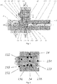
- the disclosure provides a cell culture and experiment device, which includes a central distribution compartment 1, a culture compartment 2, a treatment compartment 3, and pipelines 4 for delivering liquid between the central distribution compartment 1 and the culture compartment 2 and between the central distribution compartment 1 and the treatment compartment 3, wherein a distribution chamber 11 and a piston 12 capable of moving back and forth in the distribution chamber 11 to change the working volume of the distribution chamber 11 are provided in the central distribution compartment 1, and a distribution valve 13 for controlling the distribution chamber 11 to be communicated with any pipeline 4 is arranged at the bottom end of the distribution chamber 11 in the central distribution compartment 1.
- the central distribution compartment 1 the culture compartment 2 and the treatment compartment 3 are arranged separately, the central distribution compartment 1 surrounds the distribution valve 13 to form a plurality of mounting surfaces which can be connected to the culture compartment 2 or the treatment compartment 3, three central pipelines 14 leading from the distribution valve 13 to three mounting surfaces are arranged on the central distribution compartment 1,
- the distribution valve 13 includes a central cylinder hole 131 provided at the bottom end of the distribution chamber 11 and a central valve element 132 which is inserted into the central cylinder hole 131 and can rotate in the central cylinder hole 131, a central flow channel 133 is provided on the central valve element 132, and when the central valve element 132 rotates, the central flow channel 133 can communicate the distribution chamber 11 with any central pipeline 14.
- a protrusion 134 is arranged at one end of the central valve element 132 of the distribution valve 13, and a fixed element 135 (for example, a Seeger clamping ring or a coil spring) is arranged at the other end of the central valve element 132 and configured to fix the central valve element 132 to a specific axial direction of the central cylinder hole 131.
- the fixed element 135 may take the place of the protrusion 134 for fixing the axial direction.
- the central flow channel 133 on the central valve element 132 may be of different shapes.
- the central flow channel 133 may pass through the central valve element 132 so as to be connected to the central pipelines 14, two ends facing the central pipelines 14.
- the central flow channel 133 is located on the periphery of the central valve element 132 and is configured to be connected to the adjacent central pipelines 14. In the present embodiment, an angle between the adjacent central pipelines 14 is 90 degrees. By adjusting the length of the central flow channel 133, the central flow channel 133 may adapt to an included angle of smaller than or greater than 90 degrees.
- Two first elastic sealing elements 136 are arranged on two sides of the central flow channel 133 on the central valve element 132 and are configured to prevent liquid from leaking along the long axis of the central valve element 132.
- Figs. 3-7 illustrate four working positions of the distribution valve 13.
- the central valve element 132 rotates to a position I
- the culture compartment 2 is connected to the distribution chamber 11.
- the treatment compartment 3 is communicated with the lower central pipeline 14, and liquid can be delivered by means of an external pump.
- the central valve element 132 rotates to a position III, the culture compartment 2 is connected to the treatment compartment 3, and the distribution chamber 11 is connected to the lower central pipeline 14. It is important to note that when the central valve element 132 is at the position III, if it is not desired that the culture compartment 2 is connected to the treatment compartment 3, the position III may be switched to a position III'.
- the distribution chamber 11 is different from the central pipelines 14 in diameter, the distribution chamber 11 may be connected to the lower central pipeline 14, and meanwhile, the culture compartment 2 and the treatment compartment 3 keep closed.
- the piston 12 is inserted into the distribution chamber 11 in the central distribution compartment 1 and can move back and forth, and the piston 12 is connected to a linear drive device (omitted in the drawings) by means of a rigid part 121 and is connected with an elastic part 122.
- the elastic part 122 is attached to the front end of the rigid part 121 and can move along an axial direction of the distribution chamber 11.
- the design is commonly used for an injector and an injection pump. When the design is used for the device of the disclosure, three advantages are provided as follows.
- the distribution valve 13 is directly connected to the distribution chamber 11, and when different steps are carried out, the quantity of residual liquid between the distribution chamber 11 and the distribution valve 13 is minimized.
- the culture compartment 2 includes a culture chamber 23 formed by a cylindrical outer wall 21 and a plug 22 arranged at the front end of the outer wall 21, and a multi-way valve 24 arranged at the rear end of the outer wall 21.
- An air hole 221 is provided on the plug 22.
- the plug 22 seals the outer wall 21 using a second elastic sealing element 222.
- the multi-way valve 24 is similar to the distribution valve 13 in design, and includes a first standard shape block 241 which can be connected to the mounting surfaces and is provided with a cylinder hole and a pipeline 4, and a first valve element 242 which is inserted into the cylinder hole and can rotate in the cylinder hole.
- a first connector 243 is arranged on the first standard shape block 241.
- a first flow channel 244 is provided on the first valve element 242.
- the first flow channel 244 can isolate the culture chamber 23, or communicate the culture chamber 23 with the distribution valve 13 or connect the culture chamber 23 to the first connector 243 by means of the pipeline 4. If air is charged into the culture chamber 23 from the first connector 243, generated bubbles will supply oxygen to cells in the culture chamber 23, and meanwhile, a culture solution is stirred and mixed uniformly.
- the outer side of the outer wall 21 is sheathed by a sleeve 25, a cavity 26 is formed between the sleeve 25 and the outer wall 21, and an outlet 251 and an inlet 252 communicated with the cavity 26 are formed at the front end and rear end of the sleeve 25.
- Cooled or heated liquid can be charged into the formed cavity 26, and the liquid enters or exits from the cavity 26 through the outlet 251 and the inlet 252.
- a spiral partition wall can be arranged in the cavity 26 so as to form a channel which surrounds the outer wall 21 and is connected to the outlet 251 and the inlet 252 so as to guide the liquid to flow (omitted in the drawings).
- FIG. 10 Another solution of heating or cooling the culture chamber 23 is shown in Fig. 10 .
- a spiral guide pipe 27 surrounds the outer wall 21, and the heated or cooled liquid flows inside the spiral guide pipe 27.
- the inner diameter of the spiral guide pipe 27 is slightly smaller than the outer diameter of the culture chamber 23, so the spiral guide pipe 27 will be tightly attached to the outer wall 21.
- the spiral guide pipe 27 needs to be removed, the spiral guide pipe 27 needs to be slightly loosened so as to increase the inner diameter thereof.
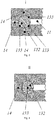
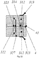
- the treatment compartment 3 provided in the disclosure includes an electric treatment compartment, a filter compartment and a cell density measurement compartment, wherein with reference to Fig. 11 and Fig. 12 , the electric treatment compartment includes a second standard shape block 311 which is provided with a pipeline 4 and can be connected to the mounting surfaces, two electrodes 312 face two sides of the pipeline 4 in the middle of the second standard shape block 311, and electric connectors 313 which can be connected to external power supplies are arranged at the outer ends of the two electrodes 312.
- the second standard shape block 311 is made from an electric insulating material, and a cell suspension can be treated under an AC, a DC or a transient current or voltage. This may be used for measuring electric properties of the cell suspension or used for transitorily changing the characteristics of cells.
- a transient high-voltage pulse may deliver macromolecules such as plasmids or oligonucleotides into the cells (electric transformation).
- the power supplies are connected to the electrodes 312 by means of the electric connectors 313, the cell suspension with a certain small volume will be located in an electric field between the two electrodes 312, and is continuously and electrically shocked.
- An electric shock frequency matches a flow speed of the cell suspension.
- an insulating partition sheet 314 is arranged between the two electrodes 312 in the pipeline 4, and the insulating partition sheet 314 forms a protrusion controlling the liquid to flow through the pipeline 4.
- the filter compartment provided in the disclosure is designed to include a first filter compartment and a second filter compartment.
- the first filter compartment includes a third standard shape block 321 which is provided with a pipeline 4 and can be connected to the mounting surfaces, a filter device which divides the pipeline 4 into a front section and a rear section is arranged in the third standard shape block 321, the filter device includes a filter membrane 322 and a porous member 323 arranged at the rear side of the filter membrane 322, the third standard shape block 321 includes a front half part 324 and a rear half part 325 which can be assembled into a whole, an inner chamber for accommodating the filter device is formed between the front half part 324 and the rear half part 325, a first spiral guide groove 326 is formed in the end surface, tightly attached to the filter membrane 322, of the front half part 324, and a first port 327 for injecting external liquid is formed for the first guide groove 326 on the side surface of the front half part
- the cell suspension flows through the filter membrane 322 and the porous member 323 by means of the pipeline 4, so as to deposit the cells on a residual liquid surface of the filter membrane 322.
- the filter membrane 322 can be replaced by splitting the front half part 324 and the rear half part 325.
- re-suspension of the cells may be implemented by means of two methods as follows.
- the second filter compartment includes a fourth standard shape block 331 which is provided with a pipeline 4 and can be connected to the mounting surfaces, an inner filter chamber 332 communicated with a pipeline 4 is formed inside the fourth standard shape block 331, an end cap 333 which is hermetically connected to the fourth standard shape block 331 and is internally provided with a pipeline 4 is arranged at the tail end of the inner filter chamber 332, a fibre filter membrane 334 extending into the inner filter chamber 332 is arranged at the inner end of the end cap 333, a second port 335 communicated with the inner filter chamber 332 is provided on the side wall of the fourth standard shape block 331, and the second port 335 leads into the inner filter chamber 332 along a tangential direction.
- the inner end of the end cap 333 forms a cylindrical protrusion.
- the cylindrical protrusion is sheathed by the fibre filter membrane 334, and the fibre filter membrane 334 is fixed and sealed by resin.
- the end cap 333 integrally seals the tail end of the inner filter chamber 332 by means of an elastic sealing element.
- the cell suspension enters the inner filter chamber 332, and flows along the outer side of the fibre filter membrane 334.
- a second spiral guide groove 336 is provided on the inner wall of the inner filter chamber 332, and the second guide groove 336 and the second port 335 are connected and surround the fibre filter membrane 334.
- the whole second filter compartment may be kept in small volume.
- the cell density measurement compartment includes a fifth standard shape block 341 which is provided with a pipeline 4 and can be connected to the mounting surfaces, an optical channel transversely penetrating through the pipeline 4 is provided on the fifth standard shape block 341, a light source 342 and a light sensor 343 are arranged at two ends of the optical channel respectively, and transparent waveguide elements 344 are arranged on two sides of the pipeline 4 between the light source 342 and the light sensor 343.
- light emitted by the light source 342 (which may be a light emitting diode) passes through one transparent waveguide element 344, interacts with the cell suspension, is received by the other transparent waveguide element 344, and then reaches the light sensor 343 (phototransistor).
- the cell density measurement of the cell suspension is further completed.
- the cell density measurement compartment and the central distribution compartment 1 are arranged integrally, that is, an optical channel transversely penetrating through the distribution chamber 11 is provided on the central distribution compartment 1, such that a light source 342 and a light sensor 343 are located at positions, on two sides of the distribution chamber 11, in the optical channel, and transparent waveguide elements are arranged on two sides of the distribution chamber 11 between the light source 342 and the light sensor 343.
- the design reduces liquid amount needed during cell density measurement, and reduces needed mechanical motions.
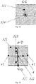
- a standard shape block having a general shape 5 is adopted in the disclosure as a basis to be applied to a culture compartment 2, a central distribution compartment 1 and all treatment compartments 3.
- Imprints of the culture compartment 2, the central distribution compartment 1 and all the treatment compartments 3 can be regarded as multiples of the general shape 5, and therefore the culture compartment 2, the central distribution compartment 1 and all the treatment compartments 3 are easily combined into different configurations.
- Fig. 21 shows a design idea, the general shape 5 is represented by a square.
- the device shown in Fig. 21 includes two culture compartments 2, a central distribution compartment 1, a treatment compartment 3 and three valves. Imprints of the central distribution compartment 1 can be regarded as three general shapes 5. Besides, the imprints of all compartments are equal to a general shape.
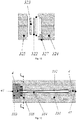
- Fig. 22 shows a composite treatment compartment.
- An electric treatment compartment and a first filter compartment described above are combined in a standard shape block.
- the combination has the advantages that the suspension volume of a pipeline 4 is reduced to the greatest extent, and the combination matches the design of the general shape 5.
- Fig. 1 in order to connect two adjacent compartments, external outlets of pipelines 4 of different compartments will be aligned along with self-border alignment of the compartments.
- Grooves 41 are provided around the external outlets of the pipelines 4 of different compartments, and sealing elements are arranged in the grooves 41 and are configured to seal the pipelines 4 between the compartments so as to prevent liquid from leaking at a joint.
- a matching hole 43 is provided on each compartment, and can realize perfect connection by means of a simple connector element 44, wherein the connector element 44 may adopt a simple cylindrical pin or flat key.
Landscapes
- Health & Medical Sciences (AREA)
- Life Sciences & Earth Sciences (AREA)
- Chemical & Material Sciences (AREA)
- Engineering & Computer Science (AREA)
- Wood Science & Technology (AREA)
- Organic Chemistry (AREA)
- Bioinformatics & Cheminformatics (AREA)
- Zoology (AREA)
- Genetics & Genomics (AREA)
- Biotechnology (AREA)
- Biomedical Technology (AREA)
- Microbiology (AREA)
- Biochemistry (AREA)
- General Engineering & Computer Science (AREA)
- General Health & Medical Sciences (AREA)
- Sustainable Development (AREA)
- Clinical Laboratory Science (AREA)
- Cell Biology (AREA)
- Analytical Chemistry (AREA)
- Physics & Mathematics (AREA)
- Electromagnetism (AREA)
- Apparatus Associated With Microorganisms And Enzymes (AREA)
Description
- The disclosure is applied to the field of biological and genetic engineering experiment devices, and particularly relates to a cell culture and experiment device.
- In the field of microbiology, particularly the fields of biological engineering, genetic engineering and the like, researchers execute experiment operations using cultured cells so as to verify their theories and experiments. These basic experiment operations include, but are not limited to,
- 1, culturing cells, particularly reproducing the cells in a liquid culture medium determined by one or more components;
- 2, measuring cell density;
- 3, separating the cells from the liquid culture medium;
- 4, re-suspending the cells using fresh liquid;
- 5, operating the cells by means of a chemical way, an electric way or other physical ways, for example, introducing genetic materials such as plasmids or oligonucleotides;
- 6, sterilizing an instrument using alcohol or other solutions; and
- 7, cleaning the instrument using water.
- A current mainstream experiment flow refers to sequentially completing the above steps in small batches by means of manual operations. Commonly used traditional experiment instruments include: a test tube, a shake flask, a shaker, a culture dish, a cuvette, an injector, a pipettor, a centrifugal machine, a filter membrane and the like. When multiple turns of experiment operations or experiment operations on a plurality of samples are executed, it is necessary to consume a great amount of time and labour.
- Although a certain degree of automation can be obtained by combining traditional instruments into a mini plant and adding a control assembly, the solution has the defects that each traditional instrument is not designed for combination, mutual specifications do not match, the combined mini plant is too large for a traditional biochemical laboratory, and a relatively large amount of needed cell culture fluid will make raw experimental materials too expensive.
- The document
WO02/18902 -
Document EP 2 204 440 discloses a portable system for analysing on-site the impregnation potential of multiple male animals. The portable system comprises a sperm sample carrier having a disc-like handle and an elongated shank. The shank defines a longitudinal channel into which a sperm sample is drawn by a vacuum. The lateral cross-section of the top of the channel has a lens shape to help focus the light passing through the optical orifices from below. The carrier is made from plastic. - The invention in its broadest form is defined in claim 1. Preferred embodiments are defined in claims 2-11.
- To solve the above problems, the disclosure provides a small cell culture and experiment device which takes the place of manual operation, is capable of completing various experimental projects, saves time and labour and avoids waste of raw experimental materials.
- To solve the technical problem, the disclosure adopts the technical solution as follows. A cell culture and experiment device may include a central distribution compartment, a culture compartment, a treatment compartment, and pipelines for delivering liquid between the central distribution compartment and the culture compartment and between the central distribution compartment and the treatment compartment, wherein a distribution chamber and a piston capable of moving back and forth in the distribution chamber to change the working volume of the distribution chamber are provided in the central distribution compartment, and a distribution valve for controlling the distribution chamber to be communicated with any pipeline is arranged at the bottom end of the distribution chamber in the central distribution compartment.
- Furthermore, as an improvement of the technical solution of the disclosure, the central distribution compartment, the culture compartment and the treatment compartment may be arranged separately, the central distribution compartment may surround the distribution valve to form a plurality of mounting surfaces which can be connected to the culture compartment or the treatment compartment, a central pipeline leading from the distribution valve to each mounting surface may be arranged on the central distribution compartment, the distribution valve may include a central cylinder hole provided at the bottom end of the distribution chamber and a central valve element which is inserted into the central cylinder hole and can rotate in the central cylinder hole, a central flow channel may be provided on the central valve element, and when the central valve element rotates, the central flow channel may communicate the distribution chamber with any central pipeline.
- Furthermore, as an improvement of the technical solution of the disclosure, the culture compartment may include a culture chamber formed by a cylindrical outer wall and a plug arranged at the front end of the outer wall, and a multi-way valve arranged at the rear end of the outer wall. An air hole may be provided on the plug. The multi-way valve may include a first standard shape block which can be connected to the mounting surfaces and is provided with a cylinder hole and a pipeline, and a first valve element which is inserted into the cylinder hole and can rotate in the cylinder hole. A first connector may be arranged on the first standard shape block. A first flow channel may be provided on the first valve element. When the first valve element rotates, the first flow channel may communicate the first connector with the culture chamber by means of the pipeline or communicate the first connector with the distribution valve or communicate the culture chamber with the distribution valve.
- Furthermore, as an improvement of the technical solution of the disclosure, the outer side of the outer wall may be sheathed by a sleeve, a cavity may be formed between the sleeve and the outer wall, an outlet and an inlet communicated with the cavity may be formed at the front end and rear end of the sleeve, and a spiral partition wall may be arranged in the cavity so as to form a channel which surrounds the outer wall and is connected to the outlet and the inlet.
- Furthermore, as an improvement of the technical solution of the disclosure, a spiral guide pipe may surround the outer wall, and the inner diameter of the spiral guide pipe may be smaller than the outer diameter of the culture chamber.
- Furthermore, as an improvement of the technical solution of the disclosure, the treatment compartment may include an electric treatment compartment, the electric treatment compartment may include a second standard shape block which is provided with a pipeline and can be connected to the mounting surfaces, two electrodes may face two sides of the pipeline in the middle of the second standard shape block, electric connectors which can be connected to external power supplies or measurers may be arranged at the outer ends of the two electrodes, an insulating partition sheet may be arranged between the two electrodes in the pipeline, and the insulating partition sheet may form a protrusion controlling liquid to flow through the pipeline.
- Furthermore, as an improvement of the technical solution of the disclosure, the treatment compartment may include a first filter compartment, the first filter compartment may include a third standard shape block which is provided with a pipeline and can be connected to the mounting surfaces, a filter device which divides the pipeline into a front section and a rear section may be arranged in the third standard shape block, the filter device may include a filter membrane and a porous member arranged at the rear side of the filter membrane, the third standard shape block may include a front half part and a rear half part which can be assembled into a whole, an inner chamber for accommodating the filter device may be formed between the front half part and the rear half part, a first spiral guide groove may be formed in the end surface, tightly attached to the filter membrane, of the front half part, and a first port for injecting external liquid may be formed for the first guide groove on the side surface of the front half part.
- Furthermore, as an improvement of the technical solution of the disclosure, the treatment compartment may include a second filter compartment, the second filter compartment may include a fourth standard shape block which is provided with a pipeline and can be connected to the mounting surfaces, an inner filter chamber communicated with a pipeline may be formed inside the fourth standard shape block, an end cap which is hermetically connected to the fourth standard shape block and is internally provided with a pipeline may be arranged at the tail end of the inner filter chamber, a fibre filter membrane extending into the inner filter chamber may be arranged at the inner end of the end cap, a second port communicated with the inner filter chamber may be provided on the side wall of the fourth standard shape block, and the second port may lead into the inner filter chamber along a tangential direction.
- Furthermore, as an improvement of the technical solution of the disclosure, a second spiral guide groove may be provided on the inner wall of the inner filter chamber, and the second guide groove and the second port may be connected and may surround the fibre filter membrane.
- Furthermore, as an improvement of the technical solution of the disclosure, the treatment compartment may include a cell density measurement compartment, the cell density measurement compartment may include a fifth standard shape block which is provided with a pipeline and can be connected to the mounting surfaces, an optical channel transversely penetrating through the pipeline may be provided on the fifth standard shape block, a light source and a light sensor may be arranged at two ends of the optical channel respectively, and transparent waveguide elements may be arranged on two sides of the pipeline between the light source and the light sensor.
- Furthermore, as an improvement of the technical solution of the disclosure, an optical channel transversely penetrating through the distribution chamber may be provided on the central distribution compartment, a light source and a light sensor may be arranged at two ends of the optical channel respectively, and transparent waveguide elements may be arranged on two sides of the distribution chamber between the light source and the light sensor.
- The disclosure has the beneficial effects as follows. The cell culture and experiment device includes at least one culture compartment, a central distribution compartment including a piston and a distribution valve, at least one treatment compartment, and a series of pipelines for delivering liquid between the compartments.
- When in use, cells grow and reproduce in the culture compartment firstly. A cell suspension can be delivered to the treatment compartment from the culture compartment by selecting a distribution valve passage and moving the piston in the distribution chamber. Treatment operations including optical density measurement, cell and culture solution separation, conductivity measurement, electric transformation, temperature rise, temperature reduction and electromagnetic radiation are further completed in the treatment compartment.
- By means of the above design, the disclosure provides a small device integrating a central distribution compartment, a culture compartment and a treatment compartment, thereby taking the place of manual operation while completing cell culture and various experimental projects, saving time and labour, avoiding waste of raw experimental materials, and reducing an opportunity of exposing experimenters under harmful substances.
- The disclosure is further illustrated below in conjunction with the drawings.
-
Fig. 1 is a basic structure diagram of an embodiment of the disclosure; -
Fig. 2 is a structural diagram of a distribution valve in an embodiment of the disclosure; -
Fig. 3 is a structural diagram illustrating that a valve element rotates to a position I in an embodiment of the disclosure; -
Fig. 4 is a structural diagram illustrating that a valve element rotates to a position II in an embodiment of the disclosure; -
Fig. 5 is a structural diagram illustrating that a valve element rotates to a position III in an embodiment of the disclosure; -
Fig. 6 is a structural diagram illustrating that a valve element rotates to a position III' in an embodiment of the disclosure; -
Fig. 7 is a structural diagram illustrating that a valve element rotates to a position IV in an embodiment of the disclosure; -
Fig. 8 is a section view of a part A-A inFig. 1 ; -
Fig. 9 is a section view of a part B-B inFig. 8 ; -
Fig. 10 is a structural diagram of an outer wall surrounded by a spiral guide pipe in an embodiment of the disclosure; -
Fig. 11 is a structural diagram of an electric treatment compartment in an embodiment of the disclosure; -
Fig. 12 is a section view of a part C-C inFig. 11 ; -
Fig. 13 is a structural diagram of a first filter compartment in an embodiment of the disclosure; -
Fig. 14 is a section view of a part D-D inFig. 13 ; -
Fig. 15 is an explosive structural diagram of a filter compartment in an embodiment of the disclosure; -
Fig. 16 is a structural diagram of a first embodiment for a second filter compartment in the disclosure; -
Fig. 17 is a section view of a part E-E inFig. 16 ; -
Fig. 18 is a structural diagram of a second embodiment for a second filter compartment in the disclosure; -
Fig. 19 is a structural diagram of a first embodiment for a cell density measurement compartment in the disclosure; -
Fig. 20 is a structural diagram of a second embodiment for a cell density measurement compartment in the disclosure; -
Fig. 21 is a diagram of an idea of adopting a general shape block as a standard shape block in the disclosure; and -
Fig. 22 is a structural diagram of a composite treatment compartment in the disclosure. - With reference to
Fig. 1 to Fig. 22 , the disclosure provides a cell culture and experiment device, which includes a central distribution compartment 1, aculture compartment 2, atreatment compartment 3, andpipelines 4 for delivering liquid between the central distribution compartment 1 and theculture compartment 2 and between the central distribution compartment 1 and thetreatment compartment 3, wherein adistribution chamber 11 and apiston 12 capable of moving back and forth in thedistribution chamber 11 to change the working volume of thedistribution chamber 11 are provided in the central distribution compartment 1, and adistribution valve 13 for controlling thedistribution chamber 11 to be communicated with anypipeline 4 is arranged at the bottom end of thedistribution chamber 11 in the central distribution compartment 1. - With reference to
Fig. 1 , the central distribution compartment 1, theculture compartment 2 and thetreatment compartment 3 are arranged separately, the central distribution compartment 1 surrounds thedistribution valve 13 to form a plurality of mounting surfaces which can be connected to theculture compartment 2 or thetreatment compartment 3, threecentral pipelines 14 leading from thedistribution valve 13 to three mounting surfaces are arranged on the central distribution compartment 1, thedistribution valve 13 includes acentral cylinder hole 131 provided at the bottom end of thedistribution chamber 11 and acentral valve element 132 which is inserted into thecentral cylinder hole 131 and can rotate in thecentral cylinder hole 131, acentral flow channel 133 is provided on thecentral valve element 132, and when thecentral valve element 132 rotates, thecentral flow channel 133 can communicate thedistribution chamber 11 with anycentral pipeline 14. - With reference to
Fig. 2 , aprotrusion 134 is arranged at one end of thecentral valve element 132 of thedistribution valve 13, and a fixed element 135 (for example, a Seeger clamping ring or a coil spring) is arranged at the other end of thecentral valve element 132 and configured to fix thecentral valve element 132 to a specific axial direction of thecentral cylinder hole 131. Obviously, the fixedelement 135 may take the place of theprotrusion 134 for fixing the axial direction. - The
central flow channel 133 on thecentral valve element 132 may be of different shapes. For example, thecentral flow channel 133 may pass through thecentral valve element 132 so as to be connected to thecentral pipelines 14, two ends facing thecentral pipelines 14. Thecentral flow channel 133 is located on the periphery of thecentral valve element 132 and is configured to be connected to the adjacentcentral pipelines 14. In the present embodiment, an angle between the adjacentcentral pipelines 14 is 90 degrees. By adjusting the length of thecentral flow channel 133, thecentral flow channel 133 may adapt to an included angle of smaller than or greater than 90 degrees. - Two first
elastic sealing elements 136 are arranged on two sides of thecentral flow channel 133 on thecentral valve element 132 and are configured to prevent liquid from leaking along the long axis of thecentral valve element 132. -
Figs. 3-7 illustrate four working positions of thedistribution valve 13. When thecentral valve element 132 rotates to a position I, theculture compartment 2 is connected to thedistribution chamber 11. Thetreatment compartment 3 is communicated with the lowercentral pipeline 14, and liquid can be delivered by means of an external pump. - When the
central valve element 132 rotates to a position II, thedistribution chamber 11 is connected to thetreatment compartment 3, and the upper and lowercentral pipelines 14 are closed. - When the
central valve element 132 rotates to a position III, theculture compartment 2 is connected to thetreatment compartment 3, and thedistribution chamber 11 is connected to the lowercentral pipeline 14. It is important to note that when thecentral valve element 132 is at the position III, if it is not desired that theculture compartment 2 is connected to thetreatment compartment 3, the position III may be switched to a position III'. Thedistribution chamber 11 is different from thecentral pipelines 14 in diameter, thedistribution chamber 11 may be connected to the lowercentral pipeline 14, and meanwhile, theculture compartment 2 and thetreatment compartment 3 keep closed. - When the
central valve element 132 rotates to a position IV, thecentral pipelines 14 and thedistribution chamber 11 are completely separated from each other, which may be applied to a standby mode of the device. - Obviously, other valves with different characteristics may also be obtained by means of other combinations of the
central pipelines 14. - In the disclosure, the
piston 12 is inserted into thedistribution chamber 11 in the central distribution compartment 1 and can move back and forth, and thepiston 12 is connected to a linear drive device (omitted in the drawings) by means of arigid part 121 and is connected with anelastic part 122. Theelastic part 122 is attached to the front end of therigid part 121 and can move along an axial direction of thedistribution chamber 11. The design is commonly used for an injector and an injection pump. When the design is used for the device of the disclosure, three advantages are provided as follows. - (i) While the
piston 12 moves along an inner wall of thedistribution chamber 11, the inner wall can be cleaned. The self-cleaning characteristic eliminates additional cleaning steps, such that the same central distribution compartment 1 can be used during treatment of various kinds of liquid. - (ii) Liquid, suspensions containing cells, gas and the like can be absorbed or pushed.
- (iii) The linear movement of the
piston 12 can be easily converted into volume, flow and the like by utilizing the cross section area of thedistribution chamber 11. - In addition, the
distribution valve 13 is directly connected to thedistribution chamber 11, and when different steps are carried out, the quantity of residual liquid between thedistribution chamber 11 and thedistribution valve 13 is minimized. - With reference to
Fig. 8 andFig. 9 , theculture compartment 2 includes aculture chamber 23 formed by a cylindricalouter wall 21 and aplug 22 arranged at the front end of theouter wall 21, and amulti-way valve 24 arranged at the rear end of theouter wall 21. Anair hole 221 is provided on theplug 22. Theplug 22 seals theouter wall 21 using a second elastic sealingelement 222. Themulti-way valve 24 is similar to thedistribution valve 13 in design, and includes a firststandard shape block 241 which can be connected to the mounting surfaces and is provided with a cylinder hole and apipeline 4, and afirst valve element 242 which is inserted into the cylinder hole and can rotate in the cylinder hole. Afirst connector 243 is arranged on the firststandard shape block 241. Afirst flow channel 244 is provided on thefirst valve element 242. When thefirst valve element 242 rotates, thefirst flow channel 244 can isolate theculture chamber 23, or communicate theculture chamber 23 with thedistribution valve 13 or connect theculture chamber 23 to thefirst connector 243 by means of thepipeline 4. If air is charged into theculture chamber 23 from thefirst connector 243, generated bubbles will supply oxygen to cells in theculture chamber 23, and meanwhile, a culture solution is stirred and mixed uniformly. - In order to control the metabolism and growth rate of cells, the outer side of the
outer wall 21 is sheathed by asleeve 25, acavity 26 is formed between thesleeve 25 and theouter wall 21, and anoutlet 251 and aninlet 252 communicated with thecavity 26 are formed at the front end and rear end of thesleeve 25. Cooled or heated liquid can be charged into the formedcavity 26, and the liquid enters or exits from thecavity 26 through theoutlet 251 and theinlet 252. In order to improve heat conduction, a spiral partition wall can be arranged in thecavity 26 so as to form a channel which surrounds theouter wall 21 and is connected to theoutlet 251 and theinlet 252 so as to guide the liquid to flow (omitted in the drawings). - Another solution of heating or cooling the
culture chamber 23 is shown inFig. 10 . Aspiral guide pipe 27 surrounds theouter wall 21, and the heated or cooled liquid flows inside thespiral guide pipe 27. The inner diameter of thespiral guide pipe 27 is slightly smaller than the outer diameter of theculture chamber 23, so thespiral guide pipe 27 will be tightly attached to theouter wall 21. When thespiral guide pipe 27 needs to be removed, thespiral guide pipe 27 needs to be slightly loosened so as to increase the inner diameter thereof. - The
treatment compartment 3 provided in the disclosure includes an electric treatment compartment, a filter compartment and a cell density measurement compartment, wherein with reference toFig. 11 andFig. 12 , the electric treatment compartment includes a secondstandard shape block 311 which is provided with apipeline 4 and can be connected to the mounting surfaces, twoelectrodes 312 face two sides of thepipeline 4 in the middle of the secondstandard shape block 311, andelectric connectors 313 which can be connected to external power supplies are arranged at the outer ends of the twoelectrodes 312. Specifically, the secondstandard shape block 311 is made from an electric insulating material, and a cell suspension can be treated under an AC, a DC or a transient current or voltage. This may be used for measuring electric properties of the cell suspension or used for transitorily changing the characteristics of cells. For example, a transient high-voltage pulse may deliver macromolecules such as plasmids or oligonucleotides into the cells (electric transformation). When in use, the power supplies are connected to theelectrodes 312 by means of theelectric connectors 313, the cell suspension with a certain small volume will be located in an electric field between the twoelectrodes 312, and is continuously and electrically shocked. An electric shock frequency matches a flow speed of the cell suspension. In order to avoid accidental contact between the twoelectrodes 312, an insulatingpartition sheet 314 is arranged between the twoelectrodes 312 in thepipeline 4, and the insulatingpartition sheet 314 forms a protrusion controlling the liquid to flow through thepipeline 4. - The filter compartment provided in the disclosure is designed to include a first filter compartment and a second filter compartment. Specifically, with reference to
Fig. 13 ,Fig. 14 andFig. 15 , the first filter compartment includes a thirdstandard shape block 321 which is provided with apipeline 4 and can be connected to the mounting surfaces, a filter device which divides thepipeline 4 into a front section and a rear section is arranged in the thirdstandard shape block 321, the filter device includes afilter membrane 322 and aporous member 323 arranged at the rear side of thefilter membrane 322, the thirdstandard shape block 321 includes a fronthalf part 324 and a rearhalf part 325 which can be assembled into a whole, an inner chamber for accommodating the filter device is formed between the fronthalf part 324 and the rearhalf part 325, a firstspiral guide groove 326 is formed in the end surface, tightly attached to thefilter membrane 322, of the fronthalf part 324, and afirst port 327 for injecting external liquid is formed for thefirst guide groove 326 on the side surface of the fronthalf part 324. When in use, the cell suspension flows through thefilter membrane 322 and theporous member 323 by means of thepipeline 4, so as to deposit the cells on a residual liquid surface of thefilter membrane 322. When thefilter membrane 322 is replaced, thefilter membrane 322 can be replaced by splitting the fronthalf part 324 and the rearhalf part 325. After filtration, re-suspension of the cells may be implemented by means of two methods as follows. - (i) Fresh liquid may reversely press the
filter membrane 322 from the reverse side of thefilter membrane 322. - (ii) Fresh liquid may be injected from the
first port 327, and the firstspiral guide groove 326 will guide the fresh liquid to flow on the residual liquid surface of thefilter membrane 322. It is important to note that thefirst port 327 needs to be connected to a valve and keeps closed in a filtration process. In this case, liquid in the cell suspension will penetrate through thefilter membrane 322, and the cells will stay on the residual liquid surface of thefilter membrane 322. - With reference to
Fig. 16 andFig. 17 , the second filter compartment includes a fourthstandard shape block 331 which is provided with apipeline 4 and can be connected to the mounting surfaces, aninner filter chamber 332 communicated with apipeline 4 is formed inside the fourthstandard shape block 331, anend cap 333 which is hermetically connected to the fourthstandard shape block 331 and is internally provided with apipeline 4 is arranged at the tail end of theinner filter chamber 332, afibre filter membrane 334 extending into theinner filter chamber 332 is arranged at the inner end of theend cap 333, asecond port 335 communicated with theinner filter chamber 332 is provided on the side wall of the fourthstandard shape block 331, and thesecond port 335 leads into theinner filter chamber 332 along a tangential direction. The inner end of theend cap 333 forms a cylindrical protrusion. The cylindrical protrusion is sheathed by thefibre filter membrane 334, and thefibre filter membrane 334 is fixed and sealed by resin. Theend cap 333 integrally seals the tail end of theinner filter chamber 332 by means of an elastic sealing element. The cell suspension enters theinner filter chamber 332, and flows along the outer side of thefibre filter membrane 334. By designing the outer diameter of theinner filter chamber 332 to be slightly larger than that of thefibre filter membrane 334, spacing between theinner filter chamber 332 and thefibre filter membrane 334 can be controlled to be very small. While the cells are deposited on the outer side of thefibre filter membrane 334, the liquid will penetrate through thefibre filter membrane 334 and flow out from thepipeline 4 of theend cap 333. For the second filter compartment, there are two methods for re-suspending the cells on the outer side of thefibre filter membrane 334. (1) Fresh liquid is injected from theend cap 333 and reversely presses thefibre filter membrane 334. (2) Fresh liquid enters theinner filter chamber 332 from thesecond port 335 along the tangential direction so as to generate circulation facilitating cell re-suspension. - With reference to
Fig. 18 , as a further improvement, in the second filter compartment, a secondspiral guide groove 336 is provided on the inner wall of theinner filter chamber 332, and thesecond guide groove 336 and thesecond port 335 are connected and surround thefibre filter membrane 334. When the cells are re-suspended, fresh liquid will flow along the secondspiral guide groove 336 and re-suspend the cells. Similarly, by controlling the inner diameter of the secondspiral guide groove 336, the whole second filter compartment may be kept in small volume. - With reference to
Fig. 19 , the cell density measurement compartment includes a fifthstandard shape block 341 which is provided with apipeline 4 and can be connected to the mounting surfaces, an optical channel transversely penetrating through thepipeline 4 is provided on the fifthstandard shape block 341, alight source 342 and alight sensor 343 are arranged at two ends of the optical channel respectively, andtransparent waveguide elements 344 are arranged on two sides of thepipeline 4 between thelight source 342 and thelight sensor 343. Specifically, light emitted by the light source 342 (which may be a light emitting diode) passes through onetransparent waveguide element 344, interacts with the cell suspension, is received by the othertransparent waveguide element 344, and then reaches the light sensor 343 (phototransistor). The cell density measurement of the cell suspension is further completed. - As shown in
Fig. 20 , the cell density measurement compartment and the central distribution compartment 1 are arranged integrally, that is, an optical channel transversely penetrating through thedistribution chamber 11 is provided on the central distribution compartment 1, such that alight source 342 and alight sensor 343 are located at positions, on two sides of thedistribution chamber 11, in the optical channel, and transparent waveguide elements are arranged on two sides of thedistribution chamber 11 between thelight source 342 and thelight sensor 343. The design reduces liquid amount needed during cell density measurement, and reduces needed mechanical motions. Once connection is established between theculture compartment 2 and the central distribution compartment 1, after the cells reach thedistribution chamber 11, cell density can be directly measured. Besides, because thedistribution chamber 11 has a larger diameter, the quantity of the measured cells is larger, and a measurement result is more accurate. - To enable an experimenter to freely select a compartment to mount the device according to an experiment flow, a standard shape block having a general shape 5 is adopted in the disclosure as a basis to be applied to a
culture compartment 2, a central distribution compartment 1 and all treatment compartments 3. Imprints of theculture compartment 2, the central distribution compartment 1 and all thetreatment compartments 3 can be regarded as multiples of the general shape 5, and therefore theculture compartment 2, the central distribution compartment 1 and all the treatment compartments 3 are easily combined into different configurations.Fig. 21 shows a design idea, the general shape 5 is represented by a square. The device shown inFig. 21 includes twoculture compartments 2, a central distribution compartment 1, atreatment compartment 3 and three valves. Imprints of the central distribution compartment 1 can be regarded as three general shapes 5. Besides, the imprints of all compartments are equal to a general shape. -
Fig. 22 shows a composite treatment compartment. An electric treatment compartment and a first filter compartment described above are combined in a standard shape block. The combination has the advantages that the suspension volume of apipeline 4 is reduced to the greatest extent, and the combination matches the design of the general shape 5. - With reference to
Fig. 1 , in order to connect two adjacent compartments, external outlets ofpipelines 4 of different compartments will be aligned along with self-border alignment of the compartments.Grooves 41 are provided around the external outlets of thepipelines 4 of different compartments, and sealing elements are arranged in thegrooves 41 and are configured to seal thepipelines 4 between the compartments so as to prevent liquid from leaking at a joint. - In order to guarantee that two adjacent compartments are completely aligned, a matching
hole 43 is provided on each compartment, and can realize perfect connection by means of asimple connector element 44, wherein theconnector element 44 may adopt a simple cylindrical pin or flat key.
Claims (11)
- A cell culture and experiment device, comprising: a central distribution compartment (1), a culture compartment (2), a treatment compartment (3), and pipelines (4) for delivering liquid between the central distribution compartment (1) and the culture compartment (2) and between the central distribution compartment (1) and the treatment compartment (3),
wherein a distribution chamber (11) and a piston (12) capable of moving back and forth in the distribution chamber (11) to change the working volume of the distribution chamber (11) are provided in the central distribution compartment (1), and
a distribution valve (13) for controlling the distribution chamber (11) to be communicated with any pipeline (4) is arranged at the bottom end of the distribution chamber (11) in the central distribution compartment (1);
in order to connect two adjacent compartments, outer outlets of pipelines (4) of different compartments are connected when the compartments themselves align and grooves (41) are provided around the outer outlets of pipelines (4) of different compartments and sealing elements are arranged in the grooves (41) to prevent liquid leakage in the joint between the compartments, to guarantee that two adjacent compartments are completely aligned, a matching hole (43) is provided on each compartment, and connection is realized by means of a simple connector element (44). - The cell culture and experiment device according to claim 1, wherein the central distribution compartment (1), the culture compartment (2) and the treatment compartment (3) are arranged separately, the central distribution compartment (1) surrounds the distribution valve (13) to form a plurality of mounting surfaces which can be connected to the culture compartment (2) or the treatment compartment (3), a central pipeline (14) leading from the distribution valve (13) to each mounting surface is arranged on the central distribution compartment (1), the distribution valve (13) comprises a central cylinder hole (131) provided at the bottom end of the distribution chamber (11) and a central valve element (132) which is inserted into the central cylinder hole (131) and can rotate in the central cylinder hole (131), a central flow channel (133) is provided on the central valve element (132), and when the central valve element (132) rotates, the central flow channel (133) can communicate the distribution chamber (11) with any central pipeline (14).
- The cell culture and experiment device according to claim 2, wherein the culture compartment (2) comprises a culture chamber (23) formed by a cylindrical outer wall (21) and a plug (22) arranged at the front end of the outer wall (21), and a multi-way valve (24) arranged at the rear end of the outer wall (21); an air hole (221) is provided on the plug (22); the multi-way valve (24) comprises a first standard shape block (241) which can be connected to the mounting surfaces and is provided with a cylinder hole and a pipeline (4), and a first valve element (242) which is inserted into the cylinder hole and can rotate in the cylinder hole; a first connector (243) is arranged on the first standard shape block (241); a first flow channel (244) is provided on the first valve element (242); and when the first valve element (242) rotates, the first flow channel (244) can communicate the first connector with the culture chamber (23) by means of the pipeline (4) or communicate the first connector with the distribution valve or communicate the culture chamber with the distribution valve.
- The cell culture and experiment device according to claim 3, wherein the outer side of the outer wall (21) is sheathed by a sleeve (25), a cavity (26) is formed between the sleeve (25) and the outer wall (21), an outlet (251) and an inlet (252) communicated with the cavity (26) are formed at the front end and rear end of the sleeve (25), and a spiral partition wall is arranged in the cavity (26) so as to form a channel which surrounds the outer wall (21) and is connected to the outlet (251) and the inlet (252).
- The cell culture and experiment device according to claim 3, wherein a spiral guide pipe (27) surrounds the outer wall (21), and the inner diameter of the spiral guide pipe (27) is smaller than the outer diameter of the culture chamber (23).
- The cell culture and experiment device according to claim 2, wherein the treatment compartment (3) comprises an electric treatment compartment, the electric treatment compartment comprises a second standard shape block (311) which is provided with a pipeline (4) and can be connected to the mounting surfaces, two electrodes (312) face two sides of the pipeline (4) in the middle of the second standard shape block (311), electric connectors (313) which can be connected to external power supplies or measurers are arranged at the outer ends of the two electrodes (312), an insulating partition sheet is arranged between the two electrodes (312) in the pipeline (4), and the insulating partition sheet forms a protrusion controlling liquid to flow through the pipeline (4).
- The cell culture and experiment device according to claim 2, wherein the treatment compartment (3) comprises a first filter compartment, the first filter compartment comprises a third standard shape block (321) which is provided with a pipeline (4) and can be connected to the mounting surfaces, a filter device which divides the pipeline (4) into a front section and a rear section is arranged in the third standard shape block (321), the filter device comprises a filter membrane (322) and a porous member (323) arranged at the rear side of the filter membrane (322), the third standard shape block (321) comprises a front half part (324) and a rear half part (324) which can be assembled into a whole, an inner chamber for accommodating the filter device is formed between the front half part (324) and the rear half part (325), a first spiral guide groove (326) is formed in the end surface, tightly attached to the filter membrane (322), of the front half part (324), and a first port (327) for injecting external liquid is formed for the first guide groove (326) on the side surface of the front half part (324).
- The cell culture and experiment device according to claim 2, wherein the treatment compartment (3) comprises a second filter compartment, the second filter compartment comprises a fourth standard shape block (331) which is provided with a pipeline (4) and can be connected to the mounting surfaces, an inner filter chamber (332) communicated with a pipeline (4) is formed inside the fourth standard shape block (331), an end cap (333) which is hermetically connected to the fourth standard shape block (331) and is internally provided with a pipeline (4) is arranged at the tail end of the inner filter chamber (332), a fibre filter membrane (334) extending into the inner filter chamber (332) is arranged at the inner end of the end cap (333), a second port (335) communicated with the inner filter chamber (332) is provided on the side wall of the fourth standard shape block (331), and the second port (335) leads into the inner filter chamber (332) along a tangential direction.
- The cell culture and experiment device according to claim 8, wherein a second spiral guide groove (336) is provided on the inner wall of the inner filter chamber (332), and the second guide groove (336) and the second port (335) are connected and surround the fibre filter membrane (334).
- The cell culture and experiment device according to claim 2, wherein the treatment compartment (3) comprises a cell density measurement compartment, the cell density measurement compartment comprises a fifth standard shape block (341) which is provided with a pipeline (4) and can be connected to the mounting surfaces, an optical channel transversely penetrating through the pipeline (4) is provided on the fifth standard shape block (341), a light source (342) and a light sensor (343) are arranged at two ends of the optical channel respectively, and transparent waveguide elements (344) are arranged on two sides of the pipeline (4) between the light source (342) and the light sensor (343).
- The cell culture and experiment device according to claim 1 or 2, wherein an optical channel transversely penetrating through the distribution chamber (11) is provided on the central distribution compartment (1), a light source (342) and a light sensor (343) are arranged at two ends of the optical channel respectively, and transparent waveguide elements (344) are arranged on two sides of the distribution chamber (11) between the light source (342) and the light sensor (343).
Applications Claiming Priority (2)
| Application Number | Priority Date | Filing Date | Title |
|---|---|---|---|
| CN201410112722.6A CN103881911B (en) | 2014-03-25 | 2014-03-25 | A kind of cell cultures and experimental installation |
| PCT/CN2014/075210 WO2015143743A1 (en) | 2014-03-25 | 2014-04-11 | Apparatus for cell culture and experiment |
Publications (3)
| Publication Number | Publication Date |
|---|---|
| EP3124595A1 EP3124595A1 (en) | 2017-02-01 |
| EP3124595A4 EP3124595A4 (en) | 2017-11-15 |
| EP3124595B1 true EP3124595B1 (en) | 2020-04-22 |
Family
ID=50951038
Family Applications (1)
| Application Number | Title | Priority Date | Filing Date |
|---|---|---|---|
| EP14887546.1A Active EP3124595B1 (en) | 2014-03-25 | 2014-04-11 | Apparatus for cell culture and experiment |
Country Status (4)
| Country | Link |
|---|---|
| US (2) | US20170130183A1 (en) |
| EP (1) | EP3124595B1 (en) |
| CN (1) | CN103881911B (en) |
| WO (1) | WO2015143743A1 (en) |
Families Citing this family (5)
| Publication number | Priority date | Publication date | Assignee | Title |
|---|---|---|---|---|
| CN103881911B (en) * | 2014-03-25 | 2015-09-09 | 广州中国科学院先进技术研究所 | A kind of cell cultures and experimental installation |
| DE102017125881B4 (en) * | 2017-11-06 | 2019-06-19 | Sartorius Stedim Biotech Gmbh | Filter module and method for detecting microorganisms |
| CN109777733B (en) * | 2019-02-26 | 2022-02-01 | 中国人民解放军军事科学院军事医学研究院 | Microwave biological effect irradiation device |
| CN112625900B (en) * | 2020-12-17 | 2022-05-17 | 西安电子科技大学 | Electromagnetic radiation cell experimental device with inclined waveguide resonant cavity |
| CN114672415B (en) * | 2022-04-08 | 2022-12-20 | 湖北明德健康科技有限公司 | Diluting device |
Family Cites Families (13)
| Publication number | Priority date | Publication date | Assignee | Title |
|---|---|---|---|---|
| ZA784744B (en) * | 1977-08-31 | 1979-08-29 | C Jottier | Apparatus for the treatment of fluids |
| WO1999042557A1 (en) * | 1998-02-19 | 1999-08-26 | Introtech | Sperm analysis system |
| US6374684B1 (en) * | 2000-08-25 | 2002-04-23 | Cepheid | Fluid control and processing system |
| JP2004069395A (en) * | 2002-08-02 | 2004-03-04 | Nec Corp | Microchip, method for manufacturing the same, and constituent detection method |
| ES2208127B1 (en) * | 2002-11-28 | 2005-09-01 | Universitat Politecnica De Catalunya | MODULAR SYSTEM OF MULTIPLES AUTOMATED MINIBIOR REACTORS FOR MULTIFUNCTIONAL SCREENNING (HTS) IN BIOTECHNOLOGY. |
| US8900828B2 (en) * | 2006-05-01 | 2014-12-02 | Cepheid | Methods and apparatus for sequential amplification reactions |
| US20080026451A1 (en) * | 2006-06-15 | 2008-01-31 | Braman Jeffrey C | System for isolating biomolecules from a sample |
| US8876765B2 (en) * | 2007-05-16 | 2014-11-04 | Smiths Medical Asd, Inc. | Pump module for use in a medical fluid dispensing system |
| US9115340B2 (en) * | 2008-08-08 | 2015-08-25 | Agency For Science Technology & Research | Microfluidic continuous flow device |
| CN102378945B (en) * | 2008-12-23 | 2015-08-05 | 佐马美国有限公司 | Flexible manufacturing system |
| US9090863B2 (en) * | 2010-05-17 | 2015-07-28 | Pall Corporation | System for seeding cells onto three dimensional scaffolds |
| CN103370409B (en) * | 2011-01-17 | 2017-05-10 | 学校法人东京女子医科大学 | Cell culture treatment system, and method for connection of modules for cell culture treatment system |
| CN103881911B (en) * | 2014-03-25 | 2015-09-09 | 广州中国科学院先进技术研究所 | A kind of cell cultures and experimental installation |
-
2014
- 2014-03-25 CN CN201410112722.6A patent/CN103881911B/en active Active
- 2014-04-11 EP EP14887546.1A patent/EP3124595B1/en active Active
- 2014-04-11 WO PCT/CN2014/075210 patent/WO2015143743A1/en active Application Filing
- 2014-04-11 US US14/434,661 patent/US20170130183A1/en not_active Abandoned
-
2016
- 2016-09-26 US US15/275,503 patent/US10407656B2/en active Active
Non-Patent Citations (1)
| Title |
|---|
| None * |
Also Published As
| Publication number | Publication date |
|---|---|
| WO2015143743A1 (en) | 2015-10-01 |
| US20170009196A1 (en) | 2017-01-12 |
| CN103881911A (en) | 2014-06-25 |
| EP3124595A1 (en) | 2017-02-01 |
| CN103881911B (en) | 2015-09-09 |
| US10407656B2 (en) | 2019-09-10 |
| US20170130183A1 (en) | 2017-05-11 |
| EP3124595A4 (en) | 2017-11-15 |
Similar Documents
| Publication | Publication Date | Title |
|---|---|---|
| US10407656B2 (en) | Cell culture and experiment device | |
| TWI806116B (en) | Well-plate incubator, method for accessing an internal chamber of incubator and system for incubation | |
| US20210245160A1 (en) | Microdroplet treatment device and use method thereof | |
| WO2015067221A1 (en) | Flow electroporation device | |
| CA3017108A1 (en) | System, method, and device for high-throughput, automated culturing of genetically modified organisms | |
| JP6411374B2 (en) | Cell culture system for adherent cell culture, and fluid supply interface with cell culture vessel | |
| US20110229927A1 (en) | Sample port of a cell culture system | |
| WO2016020992A1 (en) | Culture apparatus, culture method using same, and method for selecting aggregated cell mass | |
| AU2018205130B2 (en) | Device and method for large volume transfection | |
| CN113249215B (en) | Multi-chamber sample preparation cartridge | |
| US20230174919A1 (en) | Method for gas enrichment and simultaneously for displacement of a fluid, and system for controlling the cell environment on a corresponding multi-well cell culture plate | |
| CN107779395A (en) | A kind of high flux micro algae growth test device and method | |
| CN115254212A (en) | Single-worm direct sample-adding micro-fluidic chip and using method thereof | |
| CN103760211B (en) | A kind of microtissue transparence microstream electrophoresis frid | |
| CN210151104U (en) | Micro-fluidic chip and system comprising same | |
| ES2930540T3 (en) | bioprocessing device | |
| CN117903928A (en) | Multifunctional biological detection chip | |
| CN116445278A (en) | Microfluidic cell culture chip | |
| TW201715044A (en) | Nucleic acid extracting device | |
| CN103756901A (en) | Multifunctional mini biological cell culture device | |
| WO2024081794A2 (en) | Microtiter-plate-based high throughput perfusion bioreactor | |
| CN103764292A (en) | Device for fragmenting molecules in a sample by ultrasound | |
| WO2018210885A1 (en) | Device and method for capillary electrophoresis | |
| Perozziello et al. | A MICROFLUIDIC BIOREACTOR FOR PARAL-LEL CONTINUOUS CULTURING OF EMBRYOS | |
| BR102012028234A2 (en) | ANNULAR ROTATION BIORREACTOR FOR CELL CULTURE |
Legal Events
| Date | Code | Title | Description |
|---|---|---|---|
| PUAI | Public reference made under article 153(3) epc to a published international application that has entered the european phase |
Free format text: ORIGINAL CODE: 0009012 |
|
| STAA | Information on the status of an ep patent application or granted ep patent |
Free format text: STATUS: REQUEST FOR EXAMINATION WAS MADE |
|
| 17P | Request for examination filed |
Effective date: 20160929 |
|
| AK | Designated contracting states |
Kind code of ref document: A1 Designated state(s): AL AT BE BG CH CY CZ DE DK EE ES FI FR GB GR HR HU IE IS IT LI LT LU LV MC MK MT NL NO PL PT RO RS SE SI SK SM TR |
|
| AX | Request for extension of the european patent |
Extension state: BA ME |
|
| DAX | Request for extension of the european patent (deleted) | ||
| A4 | Supplementary search report drawn up and despatched |
Effective date: 20171012 |
|
| RIC1 | Information provided on ipc code assigned before grant |
Ipc: C12M 3/00 20060101AFI20171006BHEP |
|
| STAA | Information on the status of an ep patent application or granted ep patent |
Free format text: STATUS: EXAMINATION IS IN PROGRESS |
|
| 17Q | First examination report despatched |
Effective date: 20180918 |
|
| GRAP | Despatch of communication of intention to grant a patent |
Free format text: ORIGINAL CODE: EPIDOSNIGR1 |
|
| STAA | Information on the status of an ep patent application or granted ep patent |
Free format text: STATUS: GRANT OF PATENT IS INTENDED |
|
| INTG | Intention to grant announced |
Effective date: 20191119 |
|
| GRAS | Grant fee paid |
Free format text: ORIGINAL CODE: EPIDOSNIGR3 |
|
| GRAA | (expected) grant |
Free format text: ORIGINAL CODE: 0009210 |
|
| STAA | Information on the status of an ep patent application or granted ep patent |
Free format text: STATUS: THE PATENT HAS BEEN GRANTED |
|
| AK | Designated contracting states |
Kind code of ref document: B1 Designated state(s): AL AT BE BG CH CY CZ DE DK EE ES FI FR GB GR HR HU IE IS IT LI LT LU LV MC MK MT NL NO PL PT RO RS SE SI SK SM TR |
|
| REG | Reference to a national code |
Ref country code: CH Ref legal event code: EP |
|
| REG | Reference to a national code |
Ref country code: IE Ref legal event code: FG4D |
|
| REG | Reference to a national code |
Ref country code: DE Ref legal event code: R096 Ref document number: 602014064329 Country of ref document: DE |
|
| REG | Reference to a national code |
Ref country code: AT Ref legal event code: REF Ref document number: 1260080 Country of ref document: AT Kind code of ref document: T Effective date: 20200515 |
|
| REG | Reference to a national code |
Ref country code: LT Ref legal event code: MG4D |
|
| REG | Reference to a national code |
Ref country code: NL Ref legal event code: MP Effective date: 20200422 |
|
| PG25 | Lapsed in a contracting state [announced via postgrant information from national office to epo] |
Ref country code: SE Free format text: LAPSE BECAUSE OF FAILURE TO SUBMIT A TRANSLATION OF THE DESCRIPTION OR TO PAY THE FEE WITHIN THE PRESCRIBED TIME-LIMIT Effective date: 20200422 Ref country code: LT Free format text: LAPSE BECAUSE OF FAILURE TO SUBMIT A TRANSLATION OF THE DESCRIPTION OR TO PAY THE FEE WITHIN THE PRESCRIBED TIME-LIMIT Effective date: 20200422 Ref country code: PT Free format text: LAPSE BECAUSE OF FAILURE TO SUBMIT A TRANSLATION OF THE DESCRIPTION OR TO PAY THE FEE WITHIN THE PRESCRIBED TIME-LIMIT Effective date: 20200824 Ref country code: NL Free format text: LAPSE BECAUSE OF FAILURE TO SUBMIT A TRANSLATION OF THE DESCRIPTION OR TO PAY THE FEE WITHIN THE PRESCRIBED TIME-LIMIT Effective date: 20200422 Ref country code: GR Free format text: LAPSE BECAUSE OF FAILURE TO SUBMIT A TRANSLATION OF THE DESCRIPTION OR TO PAY THE FEE WITHIN THE PRESCRIBED TIME-LIMIT Effective date: 20200723 Ref country code: NO Free format text: LAPSE BECAUSE OF FAILURE TO SUBMIT A TRANSLATION OF THE DESCRIPTION OR TO PAY THE FEE WITHIN THE PRESCRIBED TIME-LIMIT Effective date: 20200722 Ref country code: FI Free format text: LAPSE BECAUSE OF FAILURE TO SUBMIT A TRANSLATION OF THE DESCRIPTION OR TO PAY THE FEE WITHIN THE PRESCRIBED TIME-LIMIT Effective date: 20200422 Ref country code: IS Free format text: LAPSE BECAUSE OF FAILURE TO SUBMIT A TRANSLATION OF THE DESCRIPTION OR TO PAY THE FEE WITHIN THE PRESCRIBED TIME-LIMIT Effective date: 20200822 |
|
| REG | Reference to a national code |
Ref country code: AT Ref legal event code: MK05 Ref document number: 1260080 Country of ref document: AT Kind code of ref document: T Effective date: 20200422 |
|
| PG25 | Lapsed in a contracting state [announced via postgrant information from national office to epo] |
Ref country code: BG Free format text: LAPSE BECAUSE OF FAILURE TO SUBMIT A TRANSLATION OF THE DESCRIPTION OR TO PAY THE FEE WITHIN THE PRESCRIBED TIME-LIMIT Effective date: 20200722 Ref country code: RS Free format text: LAPSE BECAUSE OF FAILURE TO SUBMIT A TRANSLATION OF THE DESCRIPTION OR TO PAY THE FEE WITHIN THE PRESCRIBED TIME-LIMIT Effective date: 20200422 Ref country code: HR Free format text: LAPSE BECAUSE OF FAILURE TO SUBMIT A TRANSLATION OF THE DESCRIPTION OR TO PAY THE FEE WITHIN THE PRESCRIBED TIME-LIMIT Effective date: 20200422 Ref country code: LV Free format text: LAPSE BECAUSE OF FAILURE TO SUBMIT A TRANSLATION OF THE DESCRIPTION OR TO PAY THE FEE WITHIN THE PRESCRIBED TIME-LIMIT Effective date: 20200422 |
|
| PG25 | Lapsed in a contracting state [announced via postgrant information from national office to epo] |
Ref country code: AL Free format text: LAPSE BECAUSE OF FAILURE TO SUBMIT A TRANSLATION OF THE DESCRIPTION OR TO PAY THE FEE WITHIN THE PRESCRIBED TIME-LIMIT Effective date: 20200422 |
|
| REG | Reference to a national code |
Ref country code: DE Ref legal event code: R097 Ref document number: 602014064329 Country of ref document: DE |
|
| PG25 | Lapsed in a contracting state [announced via postgrant information from national office to epo] |
Ref country code: IT Free format text: LAPSE BECAUSE OF FAILURE TO SUBMIT A TRANSLATION OF THE DESCRIPTION OR TO PAY THE FEE WITHIN THE PRESCRIBED TIME-LIMIT Effective date: 20200422 Ref country code: RO Free format text: LAPSE BECAUSE OF FAILURE TO SUBMIT A TRANSLATION OF THE DESCRIPTION OR TO PAY THE FEE WITHIN THE PRESCRIBED TIME-LIMIT Effective date: 20200422 Ref country code: CZ Free format text: LAPSE BECAUSE OF FAILURE TO SUBMIT A TRANSLATION OF THE DESCRIPTION OR TO PAY THE FEE WITHIN THE PRESCRIBED TIME-LIMIT Effective date: 20200422 Ref country code: ES Free format text: LAPSE BECAUSE OF FAILURE TO SUBMIT A TRANSLATION OF THE DESCRIPTION OR TO PAY THE FEE WITHIN THE PRESCRIBED TIME-LIMIT Effective date: 20200422 Ref country code: AT Free format text: LAPSE BECAUSE OF FAILURE TO SUBMIT A TRANSLATION OF THE DESCRIPTION OR TO PAY THE FEE WITHIN THE PRESCRIBED TIME-LIMIT Effective date: 20200422 Ref country code: SM Free format text: LAPSE BECAUSE OF FAILURE TO SUBMIT A TRANSLATION OF THE DESCRIPTION OR TO PAY THE FEE WITHIN THE PRESCRIBED TIME-LIMIT Effective date: 20200422 Ref country code: EE Free format text: LAPSE BECAUSE OF FAILURE TO SUBMIT A TRANSLATION OF THE DESCRIPTION OR TO PAY THE FEE WITHIN THE PRESCRIBED TIME-LIMIT Effective date: 20200422 Ref country code: DK Free format text: LAPSE BECAUSE OF FAILURE TO SUBMIT A TRANSLATION OF THE DESCRIPTION OR TO PAY THE FEE WITHIN THE PRESCRIBED TIME-LIMIT Effective date: 20200422 |
|
| PG25 | Lapsed in a contracting state [announced via postgrant information from national office to epo] |
Ref country code: SK Free format text: LAPSE BECAUSE OF FAILURE TO SUBMIT A TRANSLATION OF THE DESCRIPTION OR TO PAY THE FEE WITHIN THE PRESCRIBED TIME-LIMIT Effective date: 20200422 Ref country code: PL Free format text: LAPSE BECAUSE OF FAILURE TO SUBMIT A TRANSLATION OF THE DESCRIPTION OR TO PAY THE FEE WITHIN THE PRESCRIBED TIME-LIMIT Effective date: 20200422 |
|
| PLBE | No opposition filed within time limit |
Free format text: ORIGINAL CODE: 0009261 |
|
| STAA | Information on the status of an ep patent application or granted ep patent |
Free format text: STATUS: NO OPPOSITION FILED WITHIN TIME LIMIT |
|
| 26N | No opposition filed |
Effective date: 20210125 |
|
| PG25 | Lapsed in a contracting state [announced via postgrant information from national office to epo] |
Ref country code: SI Free format text: LAPSE BECAUSE OF FAILURE TO SUBMIT A TRANSLATION OF THE DESCRIPTION OR TO PAY THE FEE WITHIN THE PRESCRIBED TIME-LIMIT Effective date: 20200422 |
|
| PG25 | Lapsed in a contracting state [announced via postgrant information from national office to epo] |
Ref country code: MC Free format text: LAPSE BECAUSE OF FAILURE TO SUBMIT A TRANSLATION OF THE DESCRIPTION OR TO PAY THE FEE WITHIN THE PRESCRIBED TIME-LIMIT Effective date: 20200422 |
|
| PG25 | Lapsed in a contracting state [announced via postgrant information from national office to epo] |
Ref country code: LU Free format text: LAPSE BECAUSE OF NON-PAYMENT OF DUE FEES Effective date: 20210411 |
|
| REG | Reference to a national code |
Ref country code: BE Ref legal event code: MM Effective date: 20210430 |
|
| PG25 | Lapsed in a contracting state [announced via postgrant information from national office to epo] |
Ref country code: CH Free format text: LAPSE BECAUSE OF NON-PAYMENT OF DUE FEES Effective date: 20210430 Ref country code: LI Free format text: LAPSE BECAUSE OF NON-PAYMENT OF DUE FEES Effective date: 20210430 |
|
| PG25 | Lapsed in a contracting state [announced via postgrant information from national office to epo] |
Ref country code: IE Free format text: LAPSE BECAUSE OF NON-PAYMENT OF DUE FEES Effective date: 20210411 |
|
| PG25 | Lapsed in a contracting state [announced via postgrant information from national office to epo] |
Ref country code: BE Free format text: LAPSE BECAUSE OF NON-PAYMENT OF DUE FEES Effective date: 20210430 |
|
| PGFP | Annual fee paid to national office [announced via postgrant information from national office to epo] |
Ref country code: GB Payment date: 20220411 Year of fee payment: 9 Ref country code: FR Payment date: 20220411 Year of fee payment: 9 Ref country code: DE Payment date: 20220425 Year of fee payment: 9 |
|
| PG25 | Lapsed in a contracting state [announced via postgrant information from national office to epo] |
Ref country code: HU Free format text: LAPSE BECAUSE OF FAILURE TO SUBMIT A TRANSLATION OF THE DESCRIPTION OR TO PAY THE FEE WITHIN THE PRESCRIBED TIME-LIMIT; INVALID AB INITIO Effective date: 20140411 |
|
| PG25 | Lapsed in a contracting state [announced via postgrant information from national office to epo] |
Ref country code: CY Free format text: LAPSE BECAUSE OF FAILURE TO SUBMIT A TRANSLATION OF THE DESCRIPTION OR TO PAY THE FEE WITHIN THE PRESCRIBED TIME-LIMIT Effective date: 20200422 |
|
| REG | Reference to a national code |
Ref country code: DE Ref legal event code: R119 Ref document number: 602014064329 Country of ref document: DE |
|
| GBPC | Gb: european patent ceased through non-payment of renewal fee |
Effective date: 20230411 |
|
| PG25 | Lapsed in a contracting state [announced via postgrant information from national office to epo] |
Ref country code: GB Free format text: LAPSE BECAUSE OF NON-PAYMENT OF DUE FEES Effective date: 20230411 |
|
| PG25 | Lapsed in a contracting state [announced via postgrant information from national office to epo] |
Ref country code: GB Free format text: LAPSE BECAUSE OF NON-PAYMENT OF DUE FEES Effective date: 20230411 Ref country code: FR Free format text: LAPSE BECAUSE OF NON-PAYMENT OF DUE FEES Effective date: 20230430 Ref country code: DE Free format text: LAPSE BECAUSE OF NON-PAYMENT OF DUE FEES Effective date: 20231103 |
|
| PG25 | Lapsed in a contracting state [announced via postgrant information from national office to epo] |
Ref country code: MK Free format text: LAPSE BECAUSE OF FAILURE TO SUBMIT A TRANSLATION OF THE DESCRIPTION OR TO PAY THE FEE WITHIN THE PRESCRIBED TIME-LIMIT Effective date: 20200422 |