EP3124383A1 - Telescoping evacuation slide - Google Patents
Telescoping evacuation slide Download PDFInfo
- Publication number
- EP3124383A1 EP3124383A1 EP16181993.3A EP16181993A EP3124383A1 EP 3124383 A1 EP3124383 A1 EP 3124383A1 EP 16181993 A EP16181993 A EP 16181993A EP 3124383 A1 EP3124383 A1 EP 3124383A1
- Authority
- EP
- European Patent Office
- Prior art keywords
- slide system
- emergency slide
- rail
- telescoping
- emergency
- Prior art date
- Legal status (The legal status is an assumption and is not a legal conclusion. Google has not performed a legal analysis and makes no representation as to the accuracy of the status listed.)
- Granted
Links
Images




Classifications
-
- B—PERFORMING OPERATIONS; TRANSPORTING
- B64—AIRCRAFT; AVIATION; COSMONAUTICS
- B64D—EQUIPMENT FOR FITTING IN OR TO AIRCRAFT; FLIGHT SUITS; PARACHUTES; ARRANGEMENT OR MOUNTING OF POWER PLANTS OR PROPULSION TRANSMISSIONS IN AIRCRAFT
- B64D25/00—Emergency apparatus or devices, not otherwise provided for
- B64D25/08—Ejecting or escaping means
- B64D25/14—Inflatable escape chutes
-
- A—HUMAN NECESSITIES
- A62—LIFE-SAVING; FIRE-FIGHTING
- A62B—DEVICES, APPARATUS OR METHODS FOR LIFE-SAVING
- A62B1/00—Devices for lowering persons from buildings or the like
- A62B1/20—Devices for lowering persons from buildings or the like by making use of sliding-ropes, sliding-poles or chutes, e.g. hoses, pipes, sliding-grooves, sliding-sheets
-
- B—PERFORMING OPERATIONS; TRANSPORTING
- B63—SHIPS OR OTHER WATERBORNE VESSELS; RELATED EQUIPMENT
- B63B—SHIPS OR OTHER WATERBORNE VESSELS; EQUIPMENT FOR SHIPPING
- B63B27/00—Arrangement of ship-based loading or unloading equipment for cargo or passengers
- B63B27/28—Arrangement of ship-based loading or unloading equipment for cargo or passengers of chutes
-
- B—PERFORMING OPERATIONS; TRANSPORTING
- B64—AIRCRAFT; AVIATION; COSMONAUTICS
- B64F—GROUND OR AIRCRAFT-CARRIER-DECK INSTALLATIONS SPECIALLY ADAPTED FOR USE IN CONNECTION WITH AIRCRAFT; DESIGNING, MANUFACTURING, ASSEMBLING, CLEANING, MAINTAINING OR REPAIRING AIRCRAFT, NOT OTHERWISE PROVIDED FOR; HANDLING, TRANSPORTING, TESTING OR INSPECTING AIRCRAFT COMPONENTS, NOT OTHERWISE PROVIDED FOR
- B64F1/00—Ground or aircraft-carrier-deck installations
- B64F1/30—Ground or aircraft-carrier-deck installations for embarking or disembarking passengers
- B64F1/315—Mobile stairs
Definitions
- Typical evacuation systems employing emergency slides benefit from quick deployment as well as efficient packability of the slide in the door of the aircraft. Additionally, most typical slides used for aircraft evacuation are inflated in order to deploy, which may be time consuming.
- an emergency slide system comprising a slide having a telescoping structural support, and a slide surface.
- the emergency slide system further comprises a gas deployment device comprising a gas generator, compressed gas cylinder, or both.
- the gas deployment device may further include an aspirator, according to various embodiments.
- the telescoping structural support provides a more compact and quickly deployable system.
- an emergency slide system comprising a slide including a telescoping structural support, and a slide surface; and a gas deployment device configured to deploy said slide, wherein said telescoping structural support comprises a first rail and a second rail in bordering engagement with said slide surface, said first rail comprising a first set of telescoping segments, and said second rail, comprising second set of telescoping segments.
- said first set of telescoping segments, and said second set of telescoping segments each comprise a series of interlocking nested tubes having a closed bottom end and an open top end.
- said interlocking nested tubes have a square or circular cross section. According to another embodiment, deployment of said telescoping segments is effectuated by forcing gas through said open end.
- said gas deployment device is configured to force gas through said open end.
- said slide surface comprises a fabric wrap configured to envelope said telescoping structural support.
- corresponding telescoping segments of said first set of telescoping segments and telescoping segments of said second set of telescoping segments are attached to one another.
- said slide surface is attached between rails to each of said telescoping segments, at attachment sites on said telescoping segments.
- said emergency slide system is a component of an aircraft.
- said gas deployment device comprising a gas generator, a compressed gas cylinder, or a combination thereof.
- said gas deployment device further comprises an aspirator.
- said gas deployment device comprises a gas generator, a compressed gas cylinder, and an aspirator.
- said emergency slide system is configured to pack within a compartment of an aircraft. According to another embodiment, said emergency slide system is configured to deploy automatically upon opening said storage compartment.
- the emergency slide system further comprises a tie between said first rail and said second rail.
- an emergency slide system comprising a slide including a telescoping structural support, and a slide surface; and a gas deployment device configured to deploy said slide, wherein said telescoping structural support comprises a first rail and a second rail in bordering engagement with said slide surface, said first rail comprising a first set of telescoping segments, and said second rail, comprising second set of telescoping segments, wherein said first set of telescoping segments, and said second set of telescoping segments each comprise a series of interlocking nested tubes closed bottom end and an open top end.
- deployment of said telescoping segments is effectuated by forcing gas through said open end.
- an emergency slide system comprising: a slide including a telescoping structural support, and a slide surface; and a gas deployment device configured to deploy said slide, said gas deployment device comprising a gas generator, a compressed gas cylinder, or a combination thereof, wherein said telescoping structural support comprises a first rail and a second rail in bordering engagement with said slide surface, said first rail comprising a first set of telescoping segments, and said second rail, comprising second set of telescoping segments.
- said gas deployment device further comprises an aspirator.
- the emergency slide system is configured to deploy automatically upon opening of a compartment in which the emergency slide system is stored.
- an emergency slide system 100 comprising a slide 102 having a telescoping structural support 104 and a slide surface 106.
- Emergency slide system 100 further comprises a gas deployment device 105 configured to deploy said emergency slide system 100, comprising a gas generator 107, compressed gas cylinder 108, or both.
- Gas deployment device 105 may further include an aspirator 109, according to various embodiments.
- Emergency slide system 100 may be used during aircraft evacuation, as well as evacuation for ships and building structures, according to various embodiments.
- telescoping structural support 104 comprises a first rail 110 and a second rail 114, in bordering engagement with surface 106.
- the first rail 110 comprises a first set telescoping segments 112 and the second rail 114 comprises second set of telescoping segments 116, corresponding to the first set of telescoping segments 112.
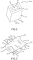
- first set of telescoping segments 112, and second set of telescoping segments 116 are each a series of interlocking nested hollow tubes 119, with each tube having a top open end 120 and an opposite bottom open end 120', except for the bottom end 122 of the smallest tube 127 being closed.
- tubes 119 may be interlockable via opposite turned interlocking lips or rims (i.e. inwardly turned rims on the bottom ends 120'of each tube (except for the bottom tube), and outwardly turned rims on the top ends 120 of each tube (except for the top tube), wherein the inwardly turned rims interlock with the outwardly turned rims of successive tubes 119 to form a seal therebetween).
- Various tube cross section geometries may be utilized, such as square, circular, I-beam, or other hollow structures, according to various embodiments.
- Telescoping structural support 104 may be formed from a rigid material such as aluminum, steel, carbon fiber composite material, or a suitable nano-composite material, according to various embodiments.
- slide surface 106 comprises a fabric, which folds and deploys along with the structural support 104.
- slide surface 106 may comprise a fabric wrap 124 having a closed bottom end 123, and an opened top end 121, configured to envelope structural support 104, wherein it would be compressed in an "accordion style" configuration in a packed state.
- Fabric wrap 124 may overlay first and second rails 110 and 114, while providing slide surface 106 therebetween.
- corresponding telescoping segments of first set of telescoping segments 112 and second set of telescoping segments 116 may be attached to one another via flexible or rigid attachment segments 125 (e.g. seam tape, and the like).
- fabric wrap 124 may be attached to first and second rails, according to various embodiments.
- slide surface 106 may be attached between rails 110, 114, by attachment to each of the telescoping segments, 112, 116 via attachment sites 118 on telescoping segments 112 and 116 (e.g. via grommets and hooks), according to various embodiments (see Figure 5 ).
- a suitable material for slide surface 106 may include a urethane rip stop material and/or a nylon based cloth with a urethane coating.
- a single lane slide for an aircraft may range from between 169 inches (4.2 m) to 400 inches (10.1m) in length.
- the length of an aircraft slide may range from 169 (4.2 m) inches to 450 inches (11.43 m), with a tube lengths of 9 inches (.22m) to 24 inches (.6m), and a tube wall thickness of around between 1/8 inch (.31cm) to 3/8 inch (.95cm).
- a 400 inch (10.1m) evacuation slide for an aircraft includes a telescoping structural support comprising carbon fiber having a tensile strength of 500,000 psi (3,447,378 kPa).
- the structural support includes 33 tubes, each approximately 12 inches (.3m) in length, and with a wall thickness of approximately 1/8 inch (.31cm) for each tube.
- the first tube has a diameter of about 8.4 inches (21cm), and the diameter of the smallest tube is around 1.25 inches (32mm).
- the angle of the deployed slide is about 28 degrees, where the term about in this context only means +/- 5 degrees.
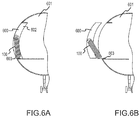
- Gas deployment device 105 may comprise a gas generator 107, a compressed gas cylinder 108, or both, according to various embodiments. Gas deployment device 105 may further include an aspirator 109. According to various embodiments, combining the gas generator 107, compressed gas cylinder 108, and aspirator 109 may be advantageous in providing rapid actuation. With reference to FIGs. 6A, 6B , 6C and 6D , according to various embodiments, emergency slide system 100 is packed and held within a storage compartment 600 preferably comprising a door of an aircraft 601, preferably inside a slide bustle 602, and is attached to the aircraft via, for example, a girt.
- a tie structure 605 may join first rail 110 to second rail 114, in order to prevent relative rotation and deflection.
- Deployment of emergency slide system 100 in an aircraft is actuated in response to the storage compartment 600 opening (see Figure 6B ).
- the storage compartment 600 shown as a door in the figures
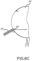
- the force of gravity causes emergency slide system 100 to fall from the aircraft storage compartment 600, upon which gas deployment device 105 is automatically actuated, causing emergency slide system 100 to deploy.
- the storage compartment 600 for storing packed emergency slide system 100 may comprise a door, a cover (e.g. decorative cover) attached to the door of the aircraft, or separate storage unit wherein the emergency slide system 100 within its separate storage unit can be installed at various locations, e.g. passenger ships, buildings, etc.
- references to "various embodiments”, “one embodiment”, “an embodiment”, “an example embodiment”, etc. indicate that the embodiment described may include a particular feature, structure, or characteristic, but every embodiment may not necessarily include the particular feature, structure, or characteristic. Moreover, such phrases are not necessarily referring to the same embodiment. Further, when a particular feature, structure, or characteristic is described in connection with an embodiment, it is submitted that it is within the knowledge of one skilled in the art to affect such feature, structure, or characteristic in connection with other embodiments whether or not explicitly described. After reading the description, it will be apparent to one skilled in the relevant art(s) how to implement the disclosure in alternative embodiments.
Landscapes
- Business, Economics & Management (AREA)
- Emergency Management (AREA)
- Engineering & Computer Science (AREA)
- General Health & Medical Sciences (AREA)
- Aviation & Aerospace Engineering (AREA)
- Health & Medical Sciences (AREA)
- Mechanical Engineering (AREA)
- Chemical & Material Sciences (AREA)
- Combustion & Propulsion (AREA)
- Ocean & Marine Engineering (AREA)
- Emergency Lowering Means (AREA)
- Bearings For Parts Moving Linearly (AREA)
- Sliding-Contact Bearings (AREA)
- Hydrogen, Water And Hydrids (AREA)
- Tents Or Canopies (AREA)
Description
- Typical evacuation systems employing emergency slides benefit from quick deployment as well as efficient packability of the slide in the door of the aircraft. Additionally, most typical slides used for aircraft evacuation are inflated in order to deploy, which may be time consuming.
- In accordance with various embodiments, disclosed is an emergency slide system comprising a slide having a telescoping structural support, and a slide surface. The emergency slide system further comprises a gas deployment device comprising a gas generator, compressed gas cylinder, or both. The gas deployment device may further include an aspirator, according to various embodiments. The telescoping structural support provides a more compact and quickly deployable system.
- In accordance with various embodiments disclosed is an emergency slide system comprising a slide including a telescoping structural support, and a slide surface; and a gas deployment device configured to deploy said slide, wherein said telescoping structural support comprises a first rail and a second rail in bordering engagement with said slide surface, said first rail comprising a first set of telescoping segments, and said second rail, comprising second set of telescoping segments.
- According to one embodiment, said first set of telescoping segments, and said second set of telescoping segments each comprise a series of interlocking nested tubes having a closed bottom end and an open top end.
- According to another embodiment, said interlocking nested tubes have a square or circular cross section. According to another embodiment, deployment of said telescoping segments is effectuated by forcing gas through said open end.
- According to another embodiment, said gas deployment device is configured to force gas through said open end. According to another embodiment, said slide surface comprises a fabric wrap configured to envelope said telescoping structural support. According to another embodiment, corresponding telescoping segments of said first set of telescoping segments and telescoping segments of said second set of telescoping segments are attached to one another.
- According to another embodiment, said slide surface is attached between rails to each of said telescoping segments, at attachment sites on said telescoping segments. According to another embodiment, said emergency slide system is a component of an aircraft. According to another embodiment, said gas deployment device comprising a gas generator, a compressed gas cylinder, or a combination thereof. According to another embodiment, said gas deployment device further comprises an aspirator. According to another embodiment, said gas deployment device comprises a gas generator, a compressed gas cylinder, and an aspirator.
- According to another embodiment, said emergency slide system is configured to pack within a compartment of an aircraft. According to another embodiment, said emergency slide system is configured to deploy automatically upon opening said storage compartment.
- According to another embodiment, the emergency slide system further comprises a tie between said first rail and said second rail.
- In accordance with various embodiments, disclosed is an emergency slide system comprising a slide including a telescoping structural support, and a slide surface; and a gas deployment device configured to deploy said slide, wherein said telescoping structural support comprises a first rail and a second rail in bordering engagement with said slide surface, said first rail comprising a first set of telescoping segments, and said second rail, comprising second set of telescoping segments, wherein said first set of telescoping segments, and said second set of telescoping segments each comprise a series of interlocking nested tubes closed bottom end and an open top end.
- According to one embodiment, deployment of said telescoping segments is effectuated by forcing gas through said open end.
- In accordance with various embodiments, disclosed an emergency slide system comprising: a slide including a telescoping structural support, and a slide surface; and a gas deployment device configured to deploy said slide, said gas deployment device comprising a gas generator, a compressed gas cylinder, or a combination thereof, wherein said telescoping structural support comprises a first rail and a second rail in bordering engagement with said slide surface, said first rail comprising a first set of telescoping segments, and said second rail, comprising second set of telescoping segments.
- According to one embodiment, said gas deployment device further comprises an aspirator. According to another embodiment, the emergency slide system is configured to deploy automatically upon opening of a compartment in which the emergency slide system is stored.
- The drawings described herein are for illustration purposes only and are not intended to limit the scope of the present disclosure in any way. The present disclosure will become more fully understood from the detailed description and the accompanying drawings wherein:
-
Figure 1A shows an aircraft comprising an emergency slide system, according to various embodiments; -
Figures 1B and C show an emergency slide system, according to various embodiments; -
Figure 2 illustrates the telescoping segments of an emergency slide system, according to various embodiments; -
Figure 3 illustrates an emergency slide system comprising a fabric wrap, according to various embodiments; -
Figure 4 illustrate the telescoping segments of an emergency slide system comprising an attachment, according to various embodiments; -
Figure 5 illustrates a slide surface connected between the telescoping segments of an emergency slide system, according to various embodiments; -
Figure 6A shows the emergency slide system packed and held within the door, according to various embodiments; -
Figure 6B shows the emergency slide system in the process of deployment, as the door of the aircraft is opened, according to various embodiments; -
Figure 6C shows the emergency slide system falling from the aircraft door, according to various embodiments; and -
Figure 6D shows the emergency slide system comprising a tie structure, according to various embodiments. - All ranges and ratio limits disclosed herein may be combined. It is to be understood that unless specifically stated otherwise, references to "a," "an," and/or "the" may include one or more than one and that reference to an item in the singular may also include the item in the plural.
- The detailed description of exemplary embodiments herein makes reference to the accompanying drawings, which show exemplary embodiments by way of illustration and its best mode, and not of limitation. While these exemplary embodiments are described in sufficient detail to enable those skilled in the art to practice the invention, it should be understood that other embodiments may be realized and that logical, chemical and mechanical changes may be made without departing from the spirit and scope of the invention. For example, the steps recited in any of the method or process descriptions may be executed in any order and are not necessarily limited to the order presented. Moreover, many of the functions or steps may be outsourced to or performed by one or more third parties. Furthermore, any reference to singular includes plural embodiments, and any reference to more than one component or step may include a singular embodiment or step. Also, any reference to attached, fixed, connected or the like may include permanent, removable, temporary, partial, full and/or any other possible attachment option. Additionally, any reference to without contact (or similar phrases) may also include reduced contact or minimal contact.
- With reference to
FIGs 1A and1B , in accordance with various embodiments, disclosed is anemergency slide system 100 comprising aslide 102 having a telescopingstructural support 104 and aslide surface 106.Emergency slide system 100 further comprises agas deployment device 105 configured to deploy saidemergency slide system 100, comprising a gas generator 107, compressedgas cylinder 108, or both.Gas deployment device 105 may further include an aspirator 109, according to various embodiments.Emergency slide system 100 may be used during aircraft evacuation, as well as evacuation for ships and building structures, according to various embodiments. - According to various embodiments, telescoping
structural support 104 comprises afirst rail 110 and asecond rail 114, in bordering engagement withsurface 106. Thefirst rail 110 comprises a firstset telescoping segments 112 and thesecond rail 114 comprises second set oftelescoping segments 116, corresponding to the first set oftelescoping segments 112. With reference toFIG. 2 , first set oftelescoping segments 112, and second set oftelescoping segments 116 are each a series of interlocking nestedhollow tubes 119, with each tube having a topopen end 120 and an opposite bottom open end 120', except for thebottom end 122 of thesmallest tube 127 being closed. According to various embodiments,tubes 119 may be interlockable via opposite turned interlocking lips or rims (i.e. inwardly turned rims on the bottom ends 120'of each tube (except for the bottom tube), and outwardly turned rims on thetop ends 120 of each tube (except for the top tube), wherein the inwardly turned rims interlock with the outwardly turned rims ofsuccessive tubes 119 to form a seal therebetween). Various tube cross section geometries may be utilized, such as square, circular, I-beam, or other hollow structures, according to various embodiments. Deployment oftelescoping segments open end 120 against closedbottom end 122, viagas deployment device 105, thus forcing the nested tubes to telescope (i.e., translate outward). Telescopingstructural support 104 may be formed from a rigid material such as aluminum, steel, carbon fiber composite material, or a suitable nano-composite material, according to various embodiments. - According to various embodiments,
slide surface 106 comprises a fabric, which folds and deploys along with thestructural support 104. With reference toFIG. 3 , according to various embodiments,slide surface 106 may comprise afabric wrap 124 having a closedbottom end 123, and an opened top end 121, configured to envelopestructural support 104, wherein it would be compressed in an "accordion style" configuration in a packed state.Fabric wrap 124 may overlay first andsecond rails slide surface 106 therebetween. In various embodiments, and with reference toFIG. 4 , corresponding telescoping segments of first set oftelescoping segments 112 and second set oftelescoping segments 116 may be attached to one another via flexible or rigid attachment segments 125 (e.g. seam tape, and the like). Additionally,fabric wrap 124 may be attached to first and second rails, according to various embodiments. - According to various embodiments,
slide surface 106 may be attached betweenrails attachment sites 118 ontelescoping segments 112 and 116 (e.g. via grommets and hooks), according to various embodiments (seeFigure 5 ). - A suitable material for
slide surface 106 may include a urethane rip stop material and/or a nylon based cloth with a urethane coating. According to various embodiments, a single lane slide for an aircraft may range from between 169 inches (4.2 m) to 400 inches (10.1m) in length. - According to various embodiments, the length of an aircraft slide may range from 169 (4.2 m) inches to 450 inches (11.43 m), with a tube lengths of 9 inches (.22m) to 24 inches (.6m), and a tube wall thickness of around between 1/8 inch (.31cm) to 3/8 inch (.95cm).
- According to an exemplary embodiment, a 400 inch (10.1m) evacuation slide for an aircraft includes a telescoping structural support comprising carbon fiber having a tensile strength of 500,000 psi (3,447,378 kPa). The structural support includes 33 tubes, each approximately 12 inches (.3m) in length, and with a wall thickness of approximately 1/8 inch (.31cm) for each tube. The first tube has a diameter of about 8.4 inches (21cm), and the diameter of the smallest tube is around 1.25 inches (32mm). The angle of the deployed slide is about 28 degrees, where the term about in this context only means +/- 5 degrees.
-
Gas deployment device 105 may comprise a gas generator 107, acompressed gas cylinder 108, or both, according to various embodiments.Gas deployment device 105 may further include an aspirator 109. According to various embodiments, combining the gas generator 107,compressed gas cylinder 108, and aspirator 109 may be advantageous in providing rapid actuation. With reference toFIGs. 6A, 6B ,6C and6D , according to various embodiments,emergency slide system 100 is packed and held within astorage compartment 600 preferably comprising a door of anaircraft 601, preferably inside aslide bustle 602, and is attached to the aircraft via, for example, a girt. According to various embodiments, atie structure 605 may joinfirst rail 110 tosecond rail 114, in order to prevent relative rotation and deflection. Deployment ofemergency slide system 100 in an aircraft is actuated in response to thestorage compartment 600 opening (seeFigure 6B ). As shown inFigure 6C , once the storage compartment 600 (shown as a door in the figures) opens, the force of gravity causesemergency slide system 100 to fall from theaircraft storage compartment 600, upon whichgas deployment device 105 is automatically actuated, causingemergency slide system 100 to deploy. According to various embodiments, thestorage compartment 600 for storing packedemergency slide system 100 may comprise a door, a cover (e.g. decorative cover) attached to the door of the aircraft, or separate storage unit wherein theemergency slide system 100 within its separate storage unit can be installed at various locations, e.g. passenger ships, buildings, etc. - Systems and methods are provided. In the detailed description herein, references to "various embodiments", "one embodiment", "an embodiment", "an example embodiment", etc., indicate that the embodiment described may include a particular feature, structure, or characteristic, but every embodiment may not necessarily include the particular feature, structure, or characteristic. Moreover, such phrases are not necessarily referring to the same embodiment. Further, when a particular feature, structure, or characteristic is described in connection with an embodiment, it is submitted that it is within the knowledge of one skilled in the art to affect such feature, structure, or characteristic in connection with other embodiments whether or not explicitly described. After reading the description, it will be apparent to one skilled in the relevant art(s) how to implement the disclosure in alternative embodiments.
- Benefits, other advantages, and solutions to problems have been described herein with regard to specific embodiments. However, the benefits, advantages, solutions to problems, and any elements that may cause any benefit, advantage, or solution to occur or become more pronounced are not to be construed as critical, required, or essential features or elements of the invention. The scope of the invention is accordingly to be limited by nothing other than the appended claims, in which reference to an element in the singular is not intended to mean "one and only one" unless explicitly so stated, but rather "one or more." Moreover, where a phrase similar to "at least one of A, B, or C" is used in the claims, it is intended that the phrase be interpreted to mean that A alone may be present in an embodiment, B alone may be present in an embodiment, C alone may be present in an embodiment, or that any combination of the elements A, B and C may be present in a single embodiment; for example, A and B, A and C, B and C, or A and B and C. Furthermore, no element, component, or method step in the present disclosure is intended to be dedicated to the public regardless of whether the element, component, or method step is explicitly recited in the claims. No claim element herein is to be construed under the provisions of 35 U.S.C. 112(f) unless the element is expressly recited using the phrase "means for." As used herein, the terms "comprises", "comprising", or any other variation thereof, are intended to cover a non-exclusive inclusion, such that a process, method, article, or apparatus that comprises a list of elements does not include only those elements but may include other elements not expressly listed or inherent to such process, method, article, or apparatus.
Claims (15)
- An emergency slide system (100) comprising:a slide (102) including a telescoping structural support (104), and a slide surface (106); anda gas deployment device (105) configured to deploy said slide (102), wherein said telescoping structural support (104) comprises a first rail (110) and a second rail (114) in bordering engagement with said slide surface (106), said first rail (110) comprising a first set of telescoping segments (112), and said second rail (114) comprising a second set of telescoping segments (116).
- The emergency slide system (100) of claim 1, said first set of telescoping segments (112) having a closed bottom end (122) and an open top end (120).
- The emergency slide system (100) of claim 1, wherein said first set of telescoping segments (112) comprise a plurality of interlocking nested tubes (119) having a closed bottom end (122) and an open top end (120).
- The emergency slide system (100) of claim 3, wherein said plurality of interlocking nested tubes (119) have a square or circular cross section.
- The emergency slide system (100) of claim 2, 3 or 4, wherein deployment of said first set of telescoping segments (112) is effectuated by forcing gas through said open end (120).
- The emergency slide system (100) of claim 5, wherein said gas deployment device (105) is configured to force gas through said open end (120).
- The emergency slide system (100) of any preceding claim, said slide surface (106) comprising a fabric wrap (124) configured to envelope said telescoping structural support (104).
- The emergency slide system (100) of any preceding claim, wherein said second set of telescoping segments (116) comprise a plurality of interlocking nested tubes (119) having a top open end (120).
- The emergency slide system (100) of any preceding claim, wherein said slide surface (106) is attached to both said first rail (110) and said second rail (114) at an attachment site (118).
- The emergency slide system (100) of any preceding claim, wherein said emergency slide system (100) is a component of an aircraft (601).
- The emergency slide system (100) of any preceding claim, said gas deployment device (105) comprising at least one of a gas generator (107), a compressed gas cylinder (108), or a combination thereof.
- The emergency slide system (100) of claim 11, said gas deployment device further comprising an aspirator.
- The emergency slide system (100) of claim 11, said gas deployment device comprising at least one of the gas generator (107), the compressed gas cylinder (108), and an aspirator (109).
- The emergency slide system (100) of any preceding claim, said emergency slide system (100) being configured to pack within a storage compartment (600), wherein, optionally said emergency slide system (100) is configured to deploy upon opening said storage compartment (600).
- The emergency slide system (100) of any preceding claim, further comprising a tie (605) between said first rail (110) and said second rail (114).
Applications Claiming Priority (1)
| Application Number | Priority Date | Filing Date | Title |
|---|---|---|---|
| US14/814,309 US9957054B2 (en) | 2015-07-30 | 2015-07-30 | Telescoping evacuation slide |
Publications (2)
| Publication Number | Publication Date |
|---|---|
| EP3124383A1 true EP3124383A1 (en) | 2017-02-01 |
| EP3124383B1 EP3124383B1 (en) | 2018-06-20 |
Family
ID=56557585
Family Applications (1)
| Application Number | Title | Priority Date | Filing Date |
|---|---|---|---|
| EP16181993.3A Active EP3124383B1 (en) | 2015-07-30 | 2016-07-29 | Telescoping evacuation slide |
Country Status (4)
| Country | Link |
|---|---|
| US (1) | US9957054B2 (en) |
| EP (1) | EP3124383B1 (en) |
| CN (1) | CN106390312B (en) |
| BR (1) | BR102016013015B1 (en) |
Cited By (1)
| Publication number | Priority date | Publication date | Assignee | Title |
|---|---|---|---|---|
| WO2019021332A1 (en) * | 2017-07-27 | 2019-01-31 | Progetech S.R.L. | Modular and orientable emergency evacuation system |
Families Citing this family (4)
| Publication number | Priority date | Publication date | Assignee | Title |
|---|---|---|---|---|
| US11292603B2 (en) * | 2018-08-31 | 2022-04-05 | Airbus Operations Gmbh | Passenger door arrangement for an aircraft segment |
| CN109367925B (en) * | 2018-11-21 | 2023-10-20 | 航宇救生装备有限公司 | Device for shaping civil aircraft slide package |
| CN110040219A (en) * | 2019-05-23 | 2019-07-23 | 王路才 | Stretcher type emergency escape device |
| CN116215806A (en) * | 2023-04-20 | 2023-06-06 | 大连海事大学 | A squeeze device for storage of inflatable evacuation slides |
Citations (7)
| Publication number | Priority date | Publication date | Assignee | Title |
|---|---|---|---|---|
| US3339690A (en) * | 1965-10-23 | 1967-09-05 | Roger G Craig | Evacuation slide |
| US4589519A (en) * | 1984-05-16 | 1986-05-20 | Hunter Danny P | Vehicle mounted fire escape chute |
| US4732233A (en) * | 1986-11-28 | 1988-03-22 | The B. F. Goodrich Company | Apparatus for reduced tear propagation |
| EP0471958A1 (en) * | 1990-08-18 | 1992-02-26 | Deutsche Airbus GmbH | Aircraft stairway |
| GB2382301A (en) * | 2003-03-20 | 2003-05-28 | Stephen Jones | Evacuation Slide |
| EP1410987A2 (en) * | 2002-10-17 | 2004-04-21 | Goodrich Corporation | Extensible evacuation slide |
| US20050230542A1 (en) * | 2004-03-22 | 2005-10-20 | The Boeing Company | Overhead space access stowable staircase |
Family Cites Families (7)
| Publication number | Priority date | Publication date | Assignee | Title |
|---|---|---|---|---|
| US4887780A (en) * | 1988-12-30 | 1989-12-19 | The United States Of America As Represented By The Administrator Of The National Aeronautics And Space Administration | Orbiter escape pole |
| GB8907707D0 (en) * | 1989-04-05 | 1989-05-17 | Mccann John J | Fire escape |
| CN2756265Y (en) * | 2004-07-14 | 2006-02-08 | 司如林 | Double arm soft slide for fire fighting rescue vehicle |
| US7641149B2 (en) * | 2007-02-13 | 2010-01-05 | The Boeing Company | Multi-exit combined evacuation slide |
| US20080223656A1 (en) * | 2007-03-13 | 2008-09-18 | Erwin Roy John | Self-deploying automatic inflatable fire escape (SAFE) |
| CN101385891A (en) * | 2007-09-11 | 2009-03-18 | 上海市向明中学 | Telescopic tower escape bar |
| US8708101B2 (en) * | 2012-02-17 | 2014-04-29 | David Patrick Bambrick | Life saving device for the home |
-
2015
- 2015-07-30 US US14/814,309 patent/US9957054B2/en active Active
-
2016
- 2016-06-07 BR BR102016013015-8A patent/BR102016013015B1/en active IP Right Grant
- 2016-07-29 CN CN201610617823.8A patent/CN106390312B/en active Active
- 2016-07-29 EP EP16181993.3A patent/EP3124383B1/en active Active
Patent Citations (7)
| Publication number | Priority date | Publication date | Assignee | Title |
|---|---|---|---|---|
| US3339690A (en) * | 1965-10-23 | 1967-09-05 | Roger G Craig | Evacuation slide |
| US4589519A (en) * | 1984-05-16 | 1986-05-20 | Hunter Danny P | Vehicle mounted fire escape chute |
| US4732233A (en) * | 1986-11-28 | 1988-03-22 | The B. F. Goodrich Company | Apparatus for reduced tear propagation |
| EP0471958A1 (en) * | 1990-08-18 | 1992-02-26 | Deutsche Airbus GmbH | Aircraft stairway |
| EP1410987A2 (en) * | 2002-10-17 | 2004-04-21 | Goodrich Corporation | Extensible evacuation slide |
| GB2382301A (en) * | 2003-03-20 | 2003-05-28 | Stephen Jones | Evacuation Slide |
| US20050230542A1 (en) * | 2004-03-22 | 2005-10-20 | The Boeing Company | Overhead space access stowable staircase |
Cited By (2)
| Publication number | Priority date | Publication date | Assignee | Title |
|---|---|---|---|---|
| WO2019021332A1 (en) * | 2017-07-27 | 2019-01-31 | Progetech S.R.L. | Modular and orientable emergency evacuation system |
| US11554274B2 (en) | 2017-07-27 | 2023-01-17 | Progetech S.R.L. | Modular and orientable emergency evacuation system |
Also Published As
| Publication number | Publication date |
|---|---|
| BR102016013015A2 (en) | 2017-01-31 |
| EP3124383B1 (en) | 2018-06-20 |
| CN106390312B (en) | 2022-03-04 |
| US9957054B2 (en) | 2018-05-01 |
| US20170029127A1 (en) | 2017-02-02 |
| CN106390312A (en) | 2017-02-15 |
| BR102016013015B1 (en) | 2022-12-20 |
Similar Documents
| Publication | Publication Date | Title |
|---|---|---|
| EP3124383B1 (en) | Telescoping evacuation slide | |
| RU2696404C2 (en) | Vehicle safety shutter (versions) and method for its folding | |
| US7762578B2 (en) | Tether guided inflatable sail panel | |
| US6773031B2 (en) | Pop-up vehicle occupant protection device | |
| US10525926B2 (en) | Vehicle seat side air bag assembly | |
| JP5969792B2 (en) | Assembling the head protection airbag | |
| JP2013052748A (en) | Airbag device | |
| US7467764B2 (en) | Fuselage mounted evacuation slide system | |
| US20140327293A1 (en) | Free-wheeling-resistant rolls for mining roof support and the combination of a mining machine and such rolls | |
| US20090102166A1 (en) | Airbag module | |
| CN1874915A (en) | Airbag divice | |
| JP6556990B2 (en) | Attaching the waterproof sheet | |
| AU2015365265A1 (en) | Thin air jack | |
| JP2005178604A (en) | Curtain air bag device | |
| US11344756B1 (en) | Universal protection system | |
| CN105209301B (en) | Inflatable gas curtain and the method for being arranged in inflatable gas curtain in storage state | |
| JP6731442B2 (en) | Tarpaulin laying device and tarpaulin laying method | |
| JP2005029035A (en) | Head part protecting air bag device | |
| US11186377B2 (en) | High pressure evacuation slide with truss-shaped side rails | |
| US8439397B1 (en) | Airbags comprising hingedly affixed non-inflatable support members | |
| JP6222676B1 (en) | Mobile tunnel soundproof door device | |
| US20220089290A1 (en) | Evacuation slide having drop stitch inflatable structure | |
| US8366051B2 (en) | Air barrier for use with an expandable structure | |
| JP2006248299A (en) | Head protection airbag | |
| JP6724842B2 (en) | Curtain airbag |
Legal Events
| Date | Code | Title | Description |
|---|---|---|---|
| PUAI | Public reference made under article 153(3) epc to a published international application that has entered the european phase |
Free format text: ORIGINAL CODE: 0009012 |
|
| STAA | Information on the status of an ep patent application or granted ep patent |
Free format text: STATUS: THE APPLICATION HAS BEEN PUBLISHED |
|
| AK | Designated contracting states |
Kind code of ref document: A1 Designated state(s): AL AT BE BG CH CY CZ DE DK EE ES FI FR GB GR HR HU IE IS IT LI LT LU LV MC MK MT NL NO PL PT RO RS SE SI SK SM TR |
|
| AX | Request for extension of the european patent |
Extension state: BA ME |
|
| STAA | Information on the status of an ep patent application or granted ep patent |
Free format text: STATUS: REQUEST FOR EXAMINATION WAS MADE |
|
| 17P | Request for examination filed |
Effective date: 20170731 |
|
| RBV | Designated contracting states (corrected) |
Designated state(s): AL AT BE BG CH CY CZ DE DK EE ES FI FR GB GR HR HU IE IS IT LI LT LU LV MC MK MT NL NO PL PT RO RS SE SI SK SM TR |
|
| RIC1 | Information provided on ipc code assigned before grant |
Ipc: B64D 25/14 20060101AFI20171206BHEP Ipc: A62B 1/20 20060101ALI20171206BHEP |
|
| GRAP | Despatch of communication of intention to grant a patent |
Free format text: ORIGINAL CODE: EPIDOSNIGR1 |
|
| STAA | Information on the status of an ep patent application or granted ep patent |
Free format text: STATUS: GRANT OF PATENT IS INTENDED |
|
| INTG | Intention to grant announced |
Effective date: 20180117 |
|
| GRAS | Grant fee paid |
Free format text: ORIGINAL CODE: EPIDOSNIGR3 |
|
| GRAA | (expected) grant |
Free format text: ORIGINAL CODE: 0009210 |
|
| STAA | Information on the status of an ep patent application or granted ep patent |
Free format text: STATUS: THE PATENT HAS BEEN GRANTED |
|
| AK | Designated contracting states |
Kind code of ref document: B1 Designated state(s): AL AT BE BG CH CY CZ DE DK EE ES FI FR GB GR HR HU IE IS IT LI LT LU LV MC MK MT NL NO PL PT RO RS SE SI SK SM TR |
|
| REG | Reference to a national code |
Ref country code: GB Ref legal event code: FG4D |
|
| REG | Reference to a national code |
Ref country code: IE Ref legal event code: FG4D |
|
| REG | Reference to a national code |
Ref country code: DE Ref legal event code: R096 Ref document number: 602016003633 Country of ref document: DE |
|
| REG | Reference to a national code |
Ref country code: AT Ref legal event code: REF Ref document number: 1010407 Country of ref document: AT Kind code of ref document: T Effective date: 20180715 |
|
| REG | Reference to a national code |
Ref country code: FR Ref legal event code: PLFP Year of fee payment: 3 |
|
| REG | Reference to a national code |
Ref country code: NL Ref legal event code: MP Effective date: 20180620 |
|
| PG25 | Lapsed in a contracting state [announced via postgrant information from national office to epo] |
Ref country code: SE Free format text: LAPSE BECAUSE OF FAILURE TO SUBMIT A TRANSLATION OF THE DESCRIPTION OR TO PAY THE FEE WITHIN THE PRESCRIBED TIME-LIMIT Effective date: 20180620 Ref country code: FI Free format text: LAPSE BECAUSE OF FAILURE TO SUBMIT A TRANSLATION OF THE DESCRIPTION OR TO PAY THE FEE WITHIN THE PRESCRIBED TIME-LIMIT Effective date: 20180620 Ref country code: NO Free format text: LAPSE BECAUSE OF FAILURE TO SUBMIT A TRANSLATION OF THE DESCRIPTION OR TO PAY THE FEE WITHIN THE PRESCRIBED TIME-LIMIT Effective date: 20180920 Ref country code: BG Free format text: LAPSE BECAUSE OF FAILURE TO SUBMIT A TRANSLATION OF THE DESCRIPTION OR TO PAY THE FEE WITHIN THE PRESCRIBED TIME-LIMIT Effective date: 20180920 Ref country code: LT Free format text: LAPSE BECAUSE OF FAILURE TO SUBMIT A TRANSLATION OF THE DESCRIPTION OR TO PAY THE FEE WITHIN THE PRESCRIBED TIME-LIMIT Effective date: 20180620 |
|
| REG | Reference to a national code |
Ref country code: LT Ref legal event code: MG4D |
|
| PG25 | Lapsed in a contracting state [announced via postgrant information from national office to epo] |
Ref country code: RS Free format text: LAPSE BECAUSE OF FAILURE TO SUBMIT A TRANSLATION OF THE DESCRIPTION OR TO PAY THE FEE WITHIN THE PRESCRIBED TIME-LIMIT Effective date: 20180620 Ref country code: HR Free format text: LAPSE BECAUSE OF FAILURE TO SUBMIT A TRANSLATION OF THE DESCRIPTION OR TO PAY THE FEE WITHIN THE PRESCRIBED TIME-LIMIT Effective date: 20180620 Ref country code: GR Free format text: LAPSE BECAUSE OF FAILURE TO SUBMIT A TRANSLATION OF THE DESCRIPTION OR TO PAY THE FEE WITHIN THE PRESCRIBED TIME-LIMIT Effective date: 20180921 Ref country code: LV Free format text: LAPSE BECAUSE OF FAILURE TO SUBMIT A TRANSLATION OF THE DESCRIPTION OR TO PAY THE FEE WITHIN THE PRESCRIBED TIME-LIMIT Effective date: 20180620 |
|
| REG | Reference to a national code |
Ref country code: AT Ref legal event code: MK05 Ref document number: 1010407 Country of ref document: AT Kind code of ref document: T Effective date: 20180620 |
|
| PG25 | Lapsed in a contracting state [announced via postgrant information from national office to epo] |
Ref country code: NL Free format text: LAPSE BECAUSE OF FAILURE TO SUBMIT A TRANSLATION OF THE DESCRIPTION OR TO PAY THE FEE WITHIN THE PRESCRIBED TIME-LIMIT Effective date: 20180620 |
|
| PG25 | Lapsed in a contracting state [announced via postgrant information from national office to epo] |
Ref country code: CZ Free format text: LAPSE BECAUSE OF FAILURE TO SUBMIT A TRANSLATION OF THE DESCRIPTION OR TO PAY THE FEE WITHIN THE PRESCRIBED TIME-LIMIT Effective date: 20180620 Ref country code: RO Free format text: LAPSE BECAUSE OF FAILURE TO SUBMIT A TRANSLATION OF THE DESCRIPTION OR TO PAY THE FEE WITHIN THE PRESCRIBED TIME-LIMIT Effective date: 20180620 Ref country code: SK Free format text: LAPSE BECAUSE OF FAILURE TO SUBMIT A TRANSLATION OF THE DESCRIPTION OR TO PAY THE FEE WITHIN THE PRESCRIBED TIME-LIMIT Effective date: 20180620 Ref country code: AT Free format text: LAPSE BECAUSE OF FAILURE TO SUBMIT A TRANSLATION OF THE DESCRIPTION OR TO PAY THE FEE WITHIN THE PRESCRIBED TIME-LIMIT Effective date: 20180620 Ref country code: PL Free format text: LAPSE BECAUSE OF FAILURE TO SUBMIT A TRANSLATION OF THE DESCRIPTION OR TO PAY THE FEE WITHIN THE PRESCRIBED TIME-LIMIT Effective date: 20180620 Ref country code: IS Free format text: LAPSE BECAUSE OF FAILURE TO SUBMIT A TRANSLATION OF THE DESCRIPTION OR TO PAY THE FEE WITHIN THE PRESCRIBED TIME-LIMIT Effective date: 20181020 Ref country code: EE Free format text: LAPSE BECAUSE OF FAILURE TO SUBMIT A TRANSLATION OF THE DESCRIPTION OR TO PAY THE FEE WITHIN THE PRESCRIBED TIME-LIMIT Effective date: 20180620 |
|
| PG25 | Lapsed in a contracting state [announced via postgrant information from national office to epo] |
Ref country code: IT Free format text: LAPSE BECAUSE OF FAILURE TO SUBMIT A TRANSLATION OF THE DESCRIPTION OR TO PAY THE FEE WITHIN THE PRESCRIBED TIME-LIMIT Effective date: 20180620 Ref country code: SM Free format text: LAPSE BECAUSE OF FAILURE TO SUBMIT A TRANSLATION OF THE DESCRIPTION OR TO PAY THE FEE WITHIN THE PRESCRIBED TIME-LIMIT Effective date: 20180620 Ref country code: ES Free format text: LAPSE BECAUSE OF FAILURE TO SUBMIT A TRANSLATION OF THE DESCRIPTION OR TO PAY THE FEE WITHIN THE PRESCRIBED TIME-LIMIT Effective date: 20180620 |
|
| REG | Reference to a national code |
Ref country code: DE Ref legal event code: R097 Ref document number: 602016003633 Country of ref document: DE |
|
| PG25 | Lapsed in a contracting state [announced via postgrant information from national office to epo] |
Ref country code: MC Free format text: LAPSE BECAUSE OF FAILURE TO SUBMIT A TRANSLATION OF THE DESCRIPTION OR TO PAY THE FEE WITHIN THE PRESCRIBED TIME-LIMIT Effective date: 20180620 Ref country code: LU Free format text: LAPSE BECAUSE OF NON-PAYMENT OF DUE FEES Effective date: 20180729 |
|
| REG | Reference to a national code |
Ref country code: BE Ref legal event code: MM Effective date: 20180731 |
|
| PLBE | No opposition filed within time limit |
Free format text: ORIGINAL CODE: 0009261 |
|
| STAA | Information on the status of an ep patent application or granted ep patent |
Free format text: STATUS: NO OPPOSITION FILED WITHIN TIME LIMIT |
|
| REG | Reference to a national code |
Ref country code: IE Ref legal event code: MM4A |
|
| 26N | No opposition filed |
Effective date: 20190321 |
|
| PG25 | Lapsed in a contracting state [announced via postgrant information from national office to epo] |
Ref country code: DK Free format text: LAPSE BECAUSE OF FAILURE TO SUBMIT A TRANSLATION OF THE DESCRIPTION OR TO PAY THE FEE WITHIN THE PRESCRIBED TIME-LIMIT Effective date: 20180620 Ref country code: BE Free format text: LAPSE BECAUSE OF NON-PAYMENT OF DUE FEES Effective date: 20180731 |
|
| PG25 | Lapsed in a contracting state [announced via postgrant information from national office to epo] |
Ref country code: IE Free format text: LAPSE BECAUSE OF NON-PAYMENT OF DUE FEES Effective date: 20180729 |
|
| PG25 | Lapsed in a contracting state [announced via postgrant information from national office to epo] |
Ref country code: SI Free format text: LAPSE BECAUSE OF FAILURE TO SUBMIT A TRANSLATION OF THE DESCRIPTION OR TO PAY THE FEE WITHIN THE PRESCRIBED TIME-LIMIT Effective date: 20180620 |
|
| PG25 | Lapsed in a contracting state [announced via postgrant information from national office to epo] |
Ref country code: AL Free format text: LAPSE BECAUSE OF FAILURE TO SUBMIT A TRANSLATION OF THE DESCRIPTION OR TO PAY THE FEE WITHIN THE PRESCRIBED TIME-LIMIT Effective date: 20180620 |
|
| PG25 | Lapsed in a contracting state [announced via postgrant information from national office to epo] |
Ref country code: MT Free format text: LAPSE BECAUSE OF NON-PAYMENT OF DUE FEES Effective date: 20180729 |
|
| REG | Reference to a national code |
Ref country code: CH Ref legal event code: PL |
|
| PG25 | Lapsed in a contracting state [announced via postgrant information from national office to epo] |
Ref country code: TR Free format text: LAPSE BECAUSE OF FAILURE TO SUBMIT A TRANSLATION OF THE DESCRIPTION OR TO PAY THE FEE WITHIN THE PRESCRIBED TIME-LIMIT Effective date: 20180620 |
|
| PG25 | Lapsed in a contracting state [announced via postgrant information from national office to epo] |
Ref country code: LI Free format text: LAPSE BECAUSE OF NON-PAYMENT OF DUE FEES Effective date: 20190731 Ref country code: CH Free format text: LAPSE BECAUSE OF NON-PAYMENT OF DUE FEES Effective date: 20190731 Ref country code: PT Free format text: LAPSE BECAUSE OF FAILURE TO SUBMIT A TRANSLATION OF THE DESCRIPTION OR TO PAY THE FEE WITHIN THE PRESCRIBED TIME-LIMIT Effective date: 20180620 |
|
| PG25 | Lapsed in a contracting state [announced via postgrant information from national office to epo] |
Ref country code: HU Free format text: LAPSE BECAUSE OF FAILURE TO SUBMIT A TRANSLATION OF THE DESCRIPTION OR TO PAY THE FEE WITHIN THE PRESCRIBED TIME-LIMIT; INVALID AB INITIO Effective date: 20160729 Ref country code: CY Free format text: LAPSE BECAUSE OF FAILURE TO SUBMIT A TRANSLATION OF THE DESCRIPTION OR TO PAY THE FEE WITHIN THE PRESCRIBED TIME-LIMIT Effective date: 20180620 Ref country code: MK Free format text: LAPSE BECAUSE OF NON-PAYMENT OF DUE FEES Effective date: 20180620 |
|
| GBPC | Gb: european patent ceased through non-payment of renewal fee |
Effective date: 20200729 |
|
| PG25 | Lapsed in a contracting state [announced via postgrant information from national office to epo] |
Ref country code: GB Free format text: LAPSE BECAUSE OF NON-PAYMENT OF DUE FEES Effective date: 20200729 |
|
| P01 | Opt-out of the competence of the unified patent court (upc) registered |
Effective date: 20230522 |
|
| PGFP | Annual fee paid to national office [announced via postgrant information from national office to epo] |
Ref country code: FR Payment date: 20250620 Year of fee payment: 10 |
|
| PGFP | Annual fee paid to national office [announced via postgrant information from national office to epo] |
Ref country code: DE Payment date: 20250620 Year of fee payment: 10 |