EP3124198B1 - Verfahren zur herstellung eines elektromechanischen schalters sowie ein elektromechanischer schalter - Google Patents
Verfahren zur herstellung eines elektromechanischen schalters sowie ein elektromechanischer schalter Download PDFInfo
- Publication number
- EP3124198B1 EP3124198B1 EP15382404.0A EP15382404A EP3124198B1 EP 3124198 B1 EP3124198 B1 EP 3124198B1 EP 15382404 A EP15382404 A EP 15382404A EP 3124198 B1 EP3124198 B1 EP 3124198B1
- Authority
- EP
- European Patent Office
- Prior art keywords
- portions
- plastic
- manufacturing
- temperature heat
- heat resistance
- Prior art date
- Legal status (The legal status is an assumption and is not a legal conclusion. Google has not performed a legal analysis and makes no representation as to the accuracy of the status listed.)
- Active
Links
- 238000000034 method Methods 0.000 title claims description 41
- 238000004519 manufacturing process Methods 0.000 title claims description 30
- 239000004033 plastic Substances 0.000 claims description 46
- 229920003023 plastic Polymers 0.000 claims description 46
- 239000000463 material Substances 0.000 claims description 16
- 229920001169 thermoplastic Polymers 0.000 claims description 13
- 239000004416 thermosoftening plastic Substances 0.000 claims description 13
- 238000002347 injection Methods 0.000 claims description 11
- 239000007924 injection Substances 0.000 claims description 11
- 238000005304 joining Methods 0.000 claims description 11
- 238000009826 distribution Methods 0.000 claims description 10
- 238000012546 transfer Methods 0.000 claims description 6
- 229920001187 thermosetting polymer Polymers 0.000 claims description 5
- 238000004513 sizing Methods 0.000 claims description 3
- 239000000126 substance Substances 0.000 claims description 2
- 239000004952 Polyamide Substances 0.000 description 7
- 229920002647 polyamide Polymers 0.000 description 7
- 238000013461 design Methods 0.000 description 4
- NFLLKCVHYJRNRH-UHFFFAOYSA-N 8-chloro-1,3-dimethyl-7H-purine-2,6-dione 2-(diphenylmethyl)oxy-N,N-dimethylethanamine Chemical compound O=C1N(C)C(=O)N(C)C2=C1NC(Cl)=N2.C=1C=CC=CC=1C(OCCN(C)C)C1=CC=CC=C1 NFLLKCVHYJRNRH-UHFFFAOYSA-N 0.000 description 2
- 230000006866 deterioration Effects 0.000 description 2
- 230000000694 effects Effects 0.000 description 2
- 230000002159 abnormal effect Effects 0.000 description 1
- 230000005856 abnormality Effects 0.000 description 1
- 238000010521 absorption reaction Methods 0.000 description 1
- 230000002411 adverse Effects 0.000 description 1
- 230000005540 biological transmission Effects 0.000 description 1
- 239000000872 buffer Substances 0.000 description 1
- 230000001186 cumulative effect Effects 0.000 description 1
- 230000003247 decreasing effect Effects 0.000 description 1
- 230000002950 deficient Effects 0.000 description 1
- 239000013013 elastic material Substances 0.000 description 1
- 238000010438 heat treatment Methods 0.000 description 1
- 239000011810 insulating material Substances 0.000 description 1
- 229910052751 metal Inorganic materials 0.000 description 1
- 238000012986 modification Methods 0.000 description 1
- 230000004048 modification Effects 0.000 description 1
- 238000001228 spectrum Methods 0.000 description 1
- 238000012360 testing method Methods 0.000 description 1
- 238000003466 welding Methods 0.000 description 1
Images


Classifications
-
- B—PERFORMING OPERATIONS; TRANSPORTING
- B29—WORKING OF PLASTICS; WORKING OF SUBSTANCES IN A PLASTIC STATE IN GENERAL
- B29C—SHAPING OR JOINING OF PLASTICS; SHAPING OF MATERIAL IN A PLASTIC STATE, NOT OTHERWISE PROVIDED FOR; AFTER-TREATMENT OF THE SHAPED PRODUCTS, e.g. REPAIRING
- B29C45/00—Injection moulding, i.e. forcing the required volume of moulding material through a nozzle into a closed mould; Apparatus therefor
- B29C45/16—Making multilayered or multicoloured articles
- B29C45/164—The moulding materials being injected simultaneously
-
- H—ELECTRICITY
- H01—ELECTRIC ELEMENTS
- H01H—ELECTRIC SWITCHES; RELAYS; SELECTORS; EMERGENCY PROTECTIVE DEVICES
- H01H9/00—Details of switching devices, not covered by groups H01H1/00 - H01H7/00
- H01H9/02—Bases, casings, or covers
-
- B—PERFORMING OPERATIONS; TRANSPORTING
- B29—WORKING OF PLASTICS; WORKING OF SUBSTANCES IN A PLASTIC STATE IN GENERAL
- B29C—SHAPING OR JOINING OF PLASTICS; SHAPING OF MATERIAL IN A PLASTIC STATE, NOT OTHERWISE PROVIDED FOR; AFTER-TREATMENT OF THE SHAPED PRODUCTS, e.g. REPAIRING
- B29C45/00—Injection moulding, i.e. forcing the required volume of moulding material through a nozzle into a closed mould; Apparatus therefor
- B29C45/16—Making multilayered or multicoloured articles
- B29C45/1642—Making multilayered or multicoloured articles having a "sandwich" structure
- B29C45/1643—Making multilayered or multicoloured articles having a "sandwich" structure from at least three different materials or with at least four layers
-
- H—ELECTRICITY
- H01—ELECTRIC ELEMENTS
- H01H—ELECTRIC SWITCHES; RELAYS; SELECTORS; EMERGENCY PROTECTIVE DEVICES
- H01H11/00—Apparatus or processes specially adapted for the manufacture of electric switches
-
- B—PERFORMING OPERATIONS; TRANSPORTING
- B29—WORKING OF PLASTICS; WORKING OF SUBSTANCES IN A PLASTIC STATE IN GENERAL
- B29L—INDEXING SCHEME ASSOCIATED WITH SUBCLASS B29C, RELATING TO PARTICULAR ARTICLES
- B29L2031/00—Other particular articles
- B29L2031/34—Electrical apparatus, e.g. sparking plugs or parts thereof
- B29L2031/3443—Switches
Definitions
- the present invention generally concerns, in a first aspect, to a method for manufacturing an electromechanical switch, comprising manufacturing an electrically insulating support by manufacturing different portions with plastics having different temperature heat resistances, and more particularly to a method comprising manufacturing the support as a single piece by at least an overmolding process and/or a multi-material injection process, and attaching electrically conductive elements to different regions thereof.
- a second aspect of the invention concerns to an electromechanical switch manufactured according to the method of the first aspect of the invention.
- Some of them comprises manufacturing the entire body of the support from only one insulating material, generally a plastic, while other combine different types of plastic, such as thermoplastics, into the same support.
- EP751865B1 discloses a housing for an electrical switch and a method for its manufacturing, where the housing is made from to thermoplastic components which are welded to one another.
- the thermoplastic components have different transmission and absorption coefficients for the spectrum of a laser beam, in order allow the laser welding.
- Some low and medium voltage applications such as the ones associated to electrical circuits of a household electrical appliance (such as an oven) require the use of electromechanical switches having electrically insulating supports with portions withstanding different temperatures.
- These supports are conventionally manufactured from only one material, such as a thermosetting material, selected to withstand the highest possible temperature, thus increasing the cost of such a support.
- thermoplastics selection based on temperature heat resistance criteria discloses such a thermoplastics selection based on temperature heat resistance criteria.
- EP0484747 discloses a puffer switch, for high voltage applications, comprising a rotor assembly inserted into a shell secured between a pair of stationary contact supports, where depending on the temperature to withstand some parts are made from a high or a low cost thermoplastic or from a thermosetting plastic.
- EP0484747 does not disclose different portions of the same part being formed from different plastics having different temperature heat resistances, nor to manufacture the entire switch support into only one piece made of different plastics having different temperature heat resistances.
- the present invention relates, in a first aspect, to a method for manufacturing an electromechanical switch, comprising manufacturing an electrically insulating support by means of the following steps:
- the method of the first aspect of the invention comprises, in a characteristic manner:
- the first plastic is also a thermoplastic or a thermosetting plastic.
- the cited manufacturing of said portions comprises performing the above mentioned selection of said first and second plastics and configuring, sizing and arranging said first and second portions with respect to each other, at least by selecting the size and shape of moulds used for said overmolding and/or multi-material injection processes, based on thermal conduction heat transfer criteria, particularly of an estimated heat distribution, in magnitude and direction, from the hottest points of portions in contact with the attached first and second electrically conductive elements towards second portion.
- said multi-material injection process is a multi-material co-injection process.
- the method of the first aspect of the invention comprises, for an embodiment, selecting said second plastic to withstand at least the highest temperature value reached at a joining region of the second portion with the first portion, said highest temperature value being calculated using said thermal conduction heat transfer criteria, wherein said joining region refers to a region joining the first and second portions once the electrically insulating support is already manufactured.
- the method of the first aspect of the invention comprises selecting the first and the second plastics based on chemical bonding affinity criteria.
- none of the plastics is a thermosetting plastic, as that kind of plastics cannot be chemically bonded.
- the method of the first aspect of the invention comprises chemically bonding and/or mechanically bonding the cited portions of the electrically insulating support.
- the method of the first aspect comprises selecting and providing a third plastic having a third temperature heat resistance higher than said second temperature heat resistance, and manufacturing the electrically insulating support as a single piece including a third portion made with said third plastic into said overmolding and/or injection process.
- the third temperature heat resistance of the third plastic is lower, equal or higher than the first temperature heat resistance.
- the third temperature heat resistance of the third plastic is lower, equal or higher than the first temperature heat resistance.
- This is useful, for example, for manufacturing a switch where, although both the first and the third portions are attached to respective electrically conductive elements and, therefore, in use, submitted to the heating caused by the circulation of electrical current there through, one of said first and third portions is submitted to a lower ambient temperature than the other one, for example because it is placed in a refrigerating chamber.
- said refrigerated portion does not need to withstand the same high temperature than the other one, and can, therefore, be made of a plastic having a lower temperature heat resistance.
- a second aspect of the invention relates to an electromechanical switch manufactured according to the method of the first aspect of the invention.
- the electrically insulating switch of the first aspect of the invention is manufactured according to the above described embodiment comprising manufacturing the electrically insulating support as a single piece including a third portion made with a third plastic, wherein the first and third portions are distanced by the second portion.
- the electromechanical switch is interconnected into an electrical circuit that is a thermostat.
- the electromechanical switch of the second aspect of the invention is a manual switch.
- the electromechanical switch of the second aspect of the invention is an automatic switch.
- Figures 1a and 1b show a simple electrically insulating support comprising three portions: a first portion 2, a second portion 1 and a third portion 12, where the second portion 1 is arranged between the other two portions 2, 12 and has a lower temperature heat resistance, but high enough to withstand the temperature to be present at the joining regions with portions 2, 12, which is estimated based on thermal conduction heat transfer criteria.
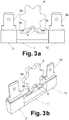
- Figures 2a, 2b and 3a, 3b show two different embodiments of the electromechanical switch of the second aspect of the invention, both including the support of Figures 1a and 1b , where two metallic terminals 5a, 5b are respectively attached to first 2 and third 12 portions, contacting and trapping respective metallic plates 3a, 3b which are selectively connected to one another through a movable metallic bridge 4, upon the orthogonal actuation of vertical actuator 7, for the embodiment of Figures 2a, 2b , or rotatory actuator 6, for the embodiment of Figures 3a, 3b .
- a movable metallic bridge 4 Only one end of the metallic bridge 4 is movable, particularly that contacting metallic plate 3b, while for the embodiment of Figures 3a, 3b both ends of the metallic bridge 4 are movable.
- FIGS 12a, 12b show another embodiment of the electromechanical switch of the second aspect of the invention, which differs from the one of Figures 3a, 3b in that metallic plate 3a and metallic bridge 4 are two respective portions of the same element or two elements joined by an elastic material, in both cases the metallic bridge 4 being movable with respect to the metallic plate 3a in an elastic manner, thus constituting a flexible switching element.
- the configuration, sizing and arranging of portions 1, 2, 12, with respect to each other, is selected based on thermal conduction heat transfer criteria.
- the heat distribution (in magnitude and direction) from the hottest points of portions 2, 12, i.e. those in contact with the metallic elements, towards portion 1 is estimated and taken into account in the design stage in order to determine the dimensions (thickness, width, length) and spatial arrangement for each of the portions 1, 2, 12.
- the plastics selection for each of the portions 1, 2, 12 is also based on said estimated heat distribution.
- this design stage is further developed in a generic manner.
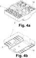
- FIGS 4a and 4b A further embodiment is shown in Figures 4a and 4b for the electrically insulating support of the electromechanical switch of the second aspect of the invention, which in this case is intended for providing four switchable electrical paths, and where portion 1 includes a central region acting as bridge between portions 2 and 12, and also a frame region laterally surrounding said portions 2, 12.
- Figures 5a and 5b show an embodiment of the electromechanical switch of the second aspect of the invention, including the support of Figures 4a and 4b , where four metallic terminals 5a are attached to respective slots of first portion 2 forming a row and, opposed thereto, four further metallic terminals 5b are attached to respective slots of third portion 12 also forming a row.
- Terminals 5a are selectively connected to terminals 5b through respective movable metallic bridges (not shown) upon the rotation of actuation shaft 13 which can be made of a plastic having a high temperature heat resistance.
- a cover 11 is coupled to the support, preferably made of a high temperature heat resistance material, such as the same than portion 1.
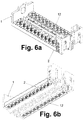
- Figures 6a and 6b show a further embodiment for the electrically insulating support of the electromechanical switch of the second aspect of the invention, which in this case is intended for providing twelve switchable electrical paths, and where portion 1 includes a central region acting as bridge between portions 2 and 12, and also two raised end walls abutting on the respective ends of portions 2, 12.
- Figures 7a and 7b show an embodiment of the electromechanical switch of the second aspect of the invention, including a support similar to the one of Figures 6a and 6b , but in this case intended for providing eight switchable electrical paths, where eight metallic terminals 5a are attached to respective slots of first portion 2 forming a row and, opposed thereto, eight further metallic terminals 5b are attached to respective slots of third portion 12 also forming a row.
- Terminals 5a are selectively connected to terminals 5b through respective movable metallic bridges (not shown) upon the actuation of plastic discs arranged about a horizontal shaft, together forming a cam, guided on the two raised end walls of portion 1 and having a shaft actuation end 13 to rotate the horizontal shaft and thus perform the closing/opening of the electrical paths.
- Figures 8a and 8b show a further embodiment of the electrically insulating support of the electromechanical switch of the second aspect of the invention, for an embodiment which differs from the one shown in Figures 1a and 1b in that only two plastic portions are included in the support, particularly a first portion 2 and a second portion 1, where the second portion 1 has a lower temperature heat resistance and is arranged between two separated regions 2a, 2b of portion 2.
- Electromechanical switches similar to the ones of Figures 2a, 2b and 3a, 3b are obtained by substituting the support of Figures 1a, 1b with the one of Figures 8a, 8b , where the two metallic terminals 5a, 5b are, in this case, respectively attached to the two separated regions 2a, 2b of the first portion 2.
- Figures 10a, 10b show another embodiment of the electromechanical switch of the second aspect of the invention, which differs from the one of Figures 3a, 3b in that it constitutes a toggle actuator switch, where the actuator is a toggle actuator including a rotary actuator 8 with several protrusions distributed in circle along one of its major faces and an actuator lever 9 arranged to move between the protrusions and displace the rotary actuator by pushing a corresponding protrusion.
- the actuator is a toggle actuator including a rotary actuator 8 with several protrusions distributed in circle along one of its major faces and an actuator lever 9 arranged to move between the protrusions and displace the rotary actuator by pushing a corresponding protrusion.
- Figures 11a, 11b differs from the one of Figures 10a, 10b in that only one end of the metallic bridge 4 is movable, particularly that contacting metallic plate 3b.
- FIG. 13a, 13b A further embodiment for the electromechanical switch of the second aspect of the invention is shown in Figures 13a, 13b , which constitutes a rocker switch, where a lever 10 is pivotable about a shaft 10a to actuate a flat metallic bridge 4 through a lower end of the lever 10.
- the temperatures that occur due to the circulation of current through the global resistance of an elementary switching circuit are within temperatures assumable by normal thermoplastics, such as polyamides, though relatively close to their limits when the ambient temperature of the specific application reaches values up to 150° C which is, therefore, added to the temperature generated by said current circulation.
- At least a bimaterial configuration and generally a multimaterial configuration, is used, selecting the plastic with a higher temperature heat resistance for the region(s) which must withstand a higher temperature and plastics with a lower temperature heat resistance for the joining regions or in other regions which do not have to withstand with high temperatures.
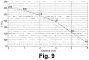
- the temperature distribution profile responds approximately to a Gaussian curve profile (darker wave), which is to be expected given the analysed distances are relatively short and the support material (polyamide) is completely uniform in its characteristics.
- a Gaussian curve profile (darker wave)
- the support material polyamide
- This temperature distribution gives an approximate gradient of temperature decreasing of about 30 °C/mm. This value is used to establish the boundaries of the zones of different material, i.e. the boundaries between portions 1, 2, 12, in relation to the estimated maximum temperature point.
Landscapes
- Engineering & Computer Science (AREA)
- Manufacturing & Machinery (AREA)
- Mechanical Engineering (AREA)
- Manufacture Of Switches (AREA)
- Thermally Actuated Switches (AREA)
Claims (10)
- Ein Verfahren zum Herstellen eines elektromechanischen Schalters, das folgende Schritte aufweist:Herstellen eines elektrisch isolierenden Trägers anhand der folgenden Schritte:Auswählen und Bereitstellen eines ersten Kunststoffs mit einer ersten Temperaturwärmebeständigkeit und eines zweiten Kunststoffs mit einer zweiten Temperaturwärmebeständigkeit, wobei die erste Temperaturwärmebeständigkeit höher als die zweite Temperaturwärmebeständigkeit ist, wobei zumindest der zweite Kunststoff ein thermoplastischer Kunststoff ist, undHerstellen zumindest eines ersten (2) und eines zweiten (1) Abschnitts des elektrisch isolierenden Trägers mit dem ersten beziehungsweise zweiten bereitgestellten Kunststoff;wobei das Verfahren dadurch gekennzeichnet ist, dass dasselbe ein Herstellen des elektrisch isolierenden Trägers in einem Stück durch zumindest einen der folgenden zwei Prozesse aufweist:einen Überformprozess, der ein Herstellen zumindest des ersten Abschnitts (2) und ein anschließendes Herstellen zumindest des zweiten Abschnitts (1) aufweist, indem zumindest manche Regionen des ersten Abschnitts (2) mit zumindest dem zweiten Kunststoff überformt werden oder umgekehrt; undein Mehrmaterial-Einspritzprozess, der ein gleichzeitiges Herstellen und Verbinden zumindest des ersten (2) und des zweiten (1) Abschnitts und/oder anderer Abschnitte des elektrisch isolierenden Trägers aufweist, die ebenfalls unterschiedliche Temperaturwärmebeständigkeiten aufweisen;und wobei das Verfahren ferner folgende Schritte aufweist:Bereitstellen zumindest eines ersten (5a), eines zweiten (5b) und eines dritten (4) elektrisch leitfähigen Elements, das so konfiguriert und angeordnet ist, dass das dritte elektrisch leitfähige Element (4) selektiv das erste (5a) und das zweite (5b) elektrisch leitfähige Element verbindet; undAnbringen des ersten (5a) und des zweiten (5b) elektrisch leitfähigen Elements jeweils an:zwei getrennten Regionen (2a, 2b) des ersten Abschnitts (2), die entweder durch den spritzgussgeformten zweiten Abschnitt (1) verbunden sind oder durch den überformten zweiten Abschnitt (1) beabstandet sind, oderdes einen an dem ersten Abschnitt (2) und des anderen an einem dritten Abschnitt (12), der aus einem Kunststoff mit einer dritten Temperaturwärmebeständigkeit hergestellt ist, die höher als die zweite Temperaturwärmebeständigkeit ist, wobei der erste (2) und der dritte (12) Abschnitt durch den zweiten Abschnitt (1) beabstandet sind.
- Das Verfahren gemäß Anspruch 1, bei dem der erste Kunststoff ebenfalls ein thermoplastischer Kunststoff oder ein wärmehärtbarer Kunststoff ist.
- Das Verfahren gemäß Anspruch 1 oder 2, bei dem das Herstellen des ersten und des zweiten Abschnitts (1, 2) folgende Schritte aufweist: Durchführen der Auswahl des ersten und des zweiten Kunststoffs und Konfigurieren, Dimensionieren und Anordnen des ersten (1) und des zweiten (2) Abschnitts in Bezug zueinander, zumindest durch Auswählen der Größe und Form von Gussformen, die für den Überform- und/oder den Mehrmaterial-Einspritzprozess verwendet werden, auf der Basis von Wärmeleitungs-Wärmeübertragungskriterien, insbesondere einer geschätzten Wärmeverteilung, hinsichtlich Größe und Richtung, von den heißesten Punkten der Abschnitte (2, 12), die mit dem angebrachten ersten (5a) und zweiten (5b) elektrisch leitfähigen Element in Berührung sind, zu dem zweiten Abschnitt (1) hin.
- Das Verfahren gemäß Anspruch 3, das ein Auswählen des zweiten Kunstoffs umfasst, um zumindest dem höchsten Temperaturwert zu widerstehen, der in einer Verbindungsregion des zweiten Abschnitts (1) mit dem ersten Abschnitt (2) entsteht, wobei der höchste Temperaturwert unter Verwendung der Wärmeleitungs-Wärmeübertragungskriterien berechnet wird, wobei die Verbindungsregion sich auf eine Region bezieht, die den ersten (1) und den zweiten (2) Abschnitt verbindet, sobald der elektrisch isolierende Träger einmal hergestellt ist.
- Das Verfahren gemäß einem der vorhergehenden Ansprüche, das ein Auswählen des ersten und des zweiten Kunststoffs auf der Basis von Chemisches-Bondverbinden-Affinätskriterien aufweist.
- Das Verfahren gemäß einem der vorhergehenden Ansprüche, das ein chemisches Bondverbinden und/oder ein mechanisches Bondverbinden der Abschnitte (1, 2) aufweist.
- Das Verfahren gemäß einem der vorhergehenden Ansprüche, das ein Auswählen und Bereitstellen eines dritten Kunststoffs mit einer dritten Temperaturwärmebeständigkeit, die höher als die zweite Temperaturwärmebeständigkeit ist, und ein Herstellen des elektrisch isolierenden Trägers in einem Stück aufweist, unter Einschließen eines dritten Abschnitts (12), der mit dem dritten Kunststoff hergestellt wird, in den Überform- und/oder Einspritzprozess.
- Ein elektromechanischer Schalter, dadurch gekennzeichnet, dass derselbe gemäß dem Verfahren gemäß einem der Ansprüche 1 bis 7 hergestellt wird, wobei der elektrisch isolierende Träger in einem Stück hergestellt wird.
- Der elektromechanische Schalter gemäß Anspruch 8, der gemäß dem Verfahren gemäß Anspruch 7 hergestellt wird, wobei der erste (2) und der dritte (12) Abschnitt durch den zweiten Abschnitt (1) beabstandet sind.
- Der elektromechanische Schalter gemäß Anspruch 8 oder 9, dadurch gekennzeichnet, dass derselbe ein manueller Schalter und/oder ein automatischer Schalter ist.
Priority Applications (3)
| Application Number | Priority Date | Filing Date | Title |
|---|---|---|---|
| PL15382404T PL3124198T3 (pl) | 2015-07-31 | 2015-07-31 | Sposób wytwarzania przełącznika elektromechanicznego oraz przełącznik elektromechaniczny |
| EP15382404.0A EP3124198B1 (de) | 2015-07-31 | 2015-07-31 | Verfahren zur herstellung eines elektromechanischen schalters sowie ein elektromechanischer schalter |
| US15/223,856 US10643803B2 (en) | 2015-07-31 | 2016-07-29 | Methods for manufacturing an electrically insulating support for an electromechanical switch and an electromechanical switch, and support and switch manufactured according to the methods |
Applications Claiming Priority (1)
| Application Number | Priority Date | Filing Date | Title |
|---|---|---|---|
| EP15382404.0A EP3124198B1 (de) | 2015-07-31 | 2015-07-31 | Verfahren zur herstellung eines elektromechanischen schalters sowie ein elektromechanischer schalter |
Publications (2)
| Publication Number | Publication Date |
|---|---|
| EP3124198A1 EP3124198A1 (de) | 2017-02-01 |
| EP3124198B1 true EP3124198B1 (de) | 2018-09-19 |
Family
ID=53887050
Family Applications (1)
| Application Number | Title | Priority Date | Filing Date |
|---|---|---|---|
| EP15382404.0A Active EP3124198B1 (de) | 2015-07-31 | 2015-07-31 | Verfahren zur herstellung eines elektromechanischen schalters sowie ein elektromechanischer schalter |
Country Status (3)
| Country | Link |
|---|---|
| US (1) | US10643803B2 (de) |
| EP (1) | EP3124198B1 (de) |
| PL (1) | PL3124198T3 (de) |
Cited By (1)
| Publication number | Priority date | Publication date | Assignee | Title |
|---|---|---|---|---|
| US10643803B2 (en) | 2015-07-31 | 2020-05-05 | Álvaro Martínez Morales | Methods for manufacturing an electrically insulating support for an electromechanical switch and an electromechanical switch, and support and switch manufactured according to the methods |
Family Cites Families (12)
| Publication number | Priority date | Publication date | Assignee | Title |
|---|---|---|---|---|
| US5153399A (en) | 1990-11-06 | 1992-10-06 | G&W Electric Company | Rotary puffer switch |
| DE4128778A1 (de) * | 1991-08-29 | 1993-03-04 | Siemens Ag | Gehaeuseteil fuer eine vor schadstoffen zu schuetzende elektrische schaltungsanordnung z. b. eines kfz-schliesssystemes |
| DE19510493A1 (de) * | 1994-03-31 | 1995-10-05 | Marquardt Gmbh | Werkstück aus Kunststoff und Herstellverfahren für ein derartiges Werkstück |
| DK67898A (da) | 1998-05-18 | 1999-11-19 | Danfoss As | Holder til brug i kølemøbel samt fremgangsmåde til fremstilling af sådan holder |
| US6093353A (en) * | 1998-08-03 | 2000-07-25 | Lear Automotive Dearborn, Inc. | Method of forming electrical components |
| US20110024275A1 (en) * | 2001-02-16 | 2011-02-03 | Integral Technologies, Inc. | Low cost key actuators and other switching device actuators manufactured from conductive loaded resin-based materials |
| US6750407B2 (en) | 2001-06-22 | 2004-06-15 | Lg Electronics Inc. | Control panel assembly for home appliances and method for manufacturing the same |
| AU2002213735A1 (en) * | 2001-11-21 | 2003-06-10 | Phonak Ag | Switch cover |
| WO2003103924A1 (en) * | 2002-06-07 | 2003-12-18 | Intier Automotive Inc. | Mult-shot injection molded component and method of manufacture |
| DE10304838A1 (de) * | 2003-02-06 | 2004-08-19 | Robert Bosch Gmbh | Verfahren zur Herstellung einer Teileeinheit |
| DE102005039555A1 (de) * | 2005-08-22 | 2007-03-01 | Abb Technology Ltd. | Verfahren zur Herstellung von Schalterpolteilen für Nieder - Mittel - und Hochspannungsschaltanlagen, sowie Schalterpolteil selbst |
| EP3124198B1 (de) | 2015-07-31 | 2018-09-19 | Martinez Korales, Alvaro | Verfahren zur herstellung eines elektromechanischen schalters sowie ein elektromechanischer schalter |
-
2015
- 2015-07-31 EP EP15382404.0A patent/EP3124198B1/de active Active
- 2015-07-31 PL PL15382404T patent/PL3124198T3/pl unknown
-
2016
- 2016-07-29 US US15/223,856 patent/US10643803B2/en active Active
Cited By (1)
| Publication number | Priority date | Publication date | Assignee | Title |
|---|---|---|---|---|
| US10643803B2 (en) | 2015-07-31 | 2020-05-05 | Álvaro Martínez Morales | Methods for manufacturing an electrically insulating support for an electromechanical switch and an electromechanical switch, and support and switch manufactured according to the methods |
Also Published As
| Publication number | Publication date |
|---|---|
| PL3124198T4 (pl) | 2019-05-31 |
| US20170032903A1 (en) | 2017-02-02 |
| PL3124198T3 (pl) | 2019-05-31 |
| US10643803B2 (en) | 2020-05-05 |
| EP3124198A1 (de) | 2017-02-01 |
Similar Documents
| Publication | Publication Date | Title |
|---|---|---|
| EP2299465B1 (de) | Temperaturabhängiger Schalter | |
| US5804798A (en) | Thermal protector with bimetal plate | |
| US20120032773A1 (en) | Thermal protector | |
| US11158471B2 (en) | Housing of electronic device, method of manufacturing housing of electronic device, and breaker having the same | |
| WO2020027052A1 (ja) | 電流遮断装置、安全回路及び2次電池パック | |
| EP3124198B1 (de) | Verfahren zur herstellung eines elektromechanischen schalters sowie ein elektromechanischer schalter | |
| KR101914186B1 (ko) | 접점 구조 | |
| TWI687956B (zh) | 斷路器之製造方法及具備該斷路器之電池包之製造方法 | |
| US20140300445A1 (en) | Thermal protector | |
| KR20200028891A (ko) | 형상 기억 와이어가 있는 개선된 액츄에이터 | |
| EP2583292B1 (de) | Wärmereaktive elektrische schalter | |
| DK3024010T3 (en) | Temperature dependent contact | |
| US10056211B2 (en) | Heat-reactive switch | |
| KR20170005644A (ko) | 온도 감응 전자부품 | |
| EP2674949B1 (de) | PTC-Vorrichtung mit Gehäuse mit elektrischen Abschaltmitteln im Fehlerfall | |
| KR101710679B1 (ko) | 압축기 모터의 과부하 보호장치 | |
| JP7397815B2 (ja) | 熱応動スイッチ素子及び電気回路 | |
| CN209981105U (zh) | 三相保护器和电气设备 | |
| KR101939006B1 (ko) | 열응동 개폐기 | |
| KR102483989B1 (ko) | 압축기 모터의 과부하 보호장치 | |
| KR100924156B1 (ko) | 온도조절장치 | |
| JP2016170861A (ja) | 電気回路切替装置及び電気回路切替システム | |
| HK1150469B (en) | Temperature-dependent switch | |
| JPH0580089B2 (de) | ||
| JP2010251308A (ja) | 温度調節装置 |
Legal Events
| Date | Code | Title | Description |
|---|---|---|---|
| PUAI | Public reference made under article 153(3) epc to a published international application that has entered the european phase |
Free format text: ORIGINAL CODE: 0009012 |
|
| STAA | Information on the status of an ep patent application or granted ep patent |
Free format text: STATUS: THE APPLICATION HAS BEEN PUBLISHED |
|
| AK | Designated contracting states |
Kind code of ref document: A1 Designated state(s): AL AT BE BG CH CY CZ DE DK EE ES FI FR GB GR HR HU IE IS IT LI LT LU LV MC MK MT NL NO PL PT RO RS SE SI SK SM TR |
|
| AX | Request for extension of the european patent |
Extension state: BA ME |
|
| STAA | Information on the status of an ep patent application or granted ep patent |
Free format text: STATUS: REQUEST FOR EXAMINATION WAS MADE |
|
| STAA | Information on the status of an ep patent application or granted ep patent |
Free format text: STATUS: EXAMINATION IS IN PROGRESS |
|
| 17P | Request for examination filed |
Effective date: 20170728 |
|
| RBV | Designated contracting states (corrected) |
Designated state(s): AL AT BE BG CH CY CZ DE DK EE ES FI FR GB GR HR HU IE IS IT LI LT LU LV MC MK MT NL NO PL PT RO RS SE SI SK SM TR |
|
| 17Q | First examination report despatched |
Effective date: 20170825 |
|
| GRAP | Despatch of communication of intention to grant a patent |
Free format text: ORIGINAL CODE: EPIDOSNIGR1 |
|
| STAA | Information on the status of an ep patent application or granted ep patent |
Free format text: STATUS: GRANT OF PATENT IS INTENDED |
|
| INTG | Intention to grant announced |
Effective date: 20180404 |
|
| GRAS | Grant fee paid |
Free format text: ORIGINAL CODE: EPIDOSNIGR3 |
|
| GRAA | (expected) grant |
Free format text: ORIGINAL CODE: 0009210 |
|
| STAA | Information on the status of an ep patent application or granted ep patent |
Free format text: STATUS: THE PATENT HAS BEEN GRANTED |
|
| AK | Designated contracting states |
Kind code of ref document: B1 Designated state(s): AL AT BE BG CH CY CZ DE DK EE ES FI FR GB GR HR HU IE IS IT LI LT LU LV MC MK MT NL NO PL PT RO RS SE SI SK SM TR |
|
| REG | Reference to a national code |
Ref country code: GB Ref legal event code: FG4D |
|
| REG | Reference to a national code |
Ref country code: CH Ref legal event code: EP |
|
| REG | Reference to a national code |
Ref country code: AT Ref legal event code: REF Ref document number: 1042735 Country of ref document: AT Kind code of ref document: T Effective date: 20181015 |
|
| REG | Reference to a national code |
Ref country code: IE Ref legal event code: FG4D |
|
| REG | Reference to a national code |
Ref country code: DE Ref legal event code: R096 Ref document number: 602015016588 Country of ref document: DE |
|
| REG | Reference to a national code |
Ref country code: NL Ref legal event code: MP Effective date: 20180919 |
|
| PG25 | Lapsed in a contracting state [announced via postgrant information from national office to epo] |
Ref country code: RS Free format text: LAPSE BECAUSE OF FAILURE TO SUBMIT A TRANSLATION OF THE DESCRIPTION OR TO PAY THE FEE WITHIN THE PRESCRIBED TIME-LIMIT Effective date: 20180919 Ref country code: SE Free format text: LAPSE BECAUSE OF FAILURE TO SUBMIT A TRANSLATION OF THE DESCRIPTION OR TO PAY THE FEE WITHIN THE PRESCRIBED TIME-LIMIT Effective date: 20180919 Ref country code: FI Free format text: LAPSE BECAUSE OF FAILURE TO SUBMIT A TRANSLATION OF THE DESCRIPTION OR TO PAY THE FEE WITHIN THE PRESCRIBED TIME-LIMIT Effective date: 20180919 Ref country code: NO Free format text: LAPSE BECAUSE OF FAILURE TO SUBMIT A TRANSLATION OF THE DESCRIPTION OR TO PAY THE FEE WITHIN THE PRESCRIBED TIME-LIMIT Effective date: 20181219 Ref country code: BG Free format text: LAPSE BECAUSE OF FAILURE TO SUBMIT A TRANSLATION OF THE DESCRIPTION OR TO PAY THE FEE WITHIN THE PRESCRIBED TIME-LIMIT Effective date: 20181219 Ref country code: GR Free format text: LAPSE BECAUSE OF FAILURE TO SUBMIT A TRANSLATION OF THE DESCRIPTION OR TO PAY THE FEE WITHIN THE PRESCRIBED TIME-LIMIT Effective date: 20181220 Ref country code: LT Free format text: LAPSE BECAUSE OF FAILURE TO SUBMIT A TRANSLATION OF THE DESCRIPTION OR TO PAY THE FEE WITHIN THE PRESCRIBED TIME-LIMIT Effective date: 20180919 |
|
| REG | Reference to a national code |
Ref country code: LT Ref legal event code: MG4D |
|
| PG25 | Lapsed in a contracting state [announced via postgrant information from national office to epo] |
Ref country code: HR Free format text: LAPSE BECAUSE OF FAILURE TO SUBMIT A TRANSLATION OF THE DESCRIPTION OR TO PAY THE FEE WITHIN THE PRESCRIBED TIME-LIMIT Effective date: 20180919 Ref country code: AL Free format text: LAPSE BECAUSE OF FAILURE TO SUBMIT A TRANSLATION OF THE DESCRIPTION OR TO PAY THE FEE WITHIN THE PRESCRIBED TIME-LIMIT Effective date: 20180919 Ref country code: LV Free format text: LAPSE BECAUSE OF FAILURE TO SUBMIT A TRANSLATION OF THE DESCRIPTION OR TO PAY THE FEE WITHIN THE PRESCRIBED TIME-LIMIT Effective date: 20180919 |
|
| PG25 | Lapsed in a contracting state [announced via postgrant information from national office to epo] |
Ref country code: RO Free format text: LAPSE BECAUSE OF FAILURE TO SUBMIT A TRANSLATION OF THE DESCRIPTION OR TO PAY THE FEE WITHIN THE PRESCRIBED TIME-LIMIT Effective date: 20180919 Ref country code: CZ Free format text: LAPSE BECAUSE OF FAILURE TO SUBMIT A TRANSLATION OF THE DESCRIPTION OR TO PAY THE FEE WITHIN THE PRESCRIBED TIME-LIMIT Effective date: 20180919 Ref country code: ES Free format text: LAPSE BECAUSE OF FAILURE TO SUBMIT A TRANSLATION OF THE DESCRIPTION OR TO PAY THE FEE WITHIN THE PRESCRIBED TIME-LIMIT Effective date: 20180919 Ref country code: NL Free format text: LAPSE BECAUSE OF FAILURE TO SUBMIT A TRANSLATION OF THE DESCRIPTION OR TO PAY THE FEE WITHIN THE PRESCRIBED TIME-LIMIT Effective date: 20180919 Ref country code: IS Free format text: LAPSE BECAUSE OF FAILURE TO SUBMIT A TRANSLATION OF THE DESCRIPTION OR TO PAY THE FEE WITHIN THE PRESCRIBED TIME-LIMIT Effective date: 20190119 Ref country code: EE Free format text: LAPSE BECAUSE OF FAILURE TO SUBMIT A TRANSLATION OF THE DESCRIPTION OR TO PAY THE FEE WITHIN THE PRESCRIBED TIME-LIMIT Effective date: 20180919 |
|
| PG25 | Lapsed in a contracting state [announced via postgrant information from national office to epo] |
Ref country code: SM Free format text: LAPSE BECAUSE OF FAILURE TO SUBMIT A TRANSLATION OF THE DESCRIPTION OR TO PAY THE FEE WITHIN THE PRESCRIBED TIME-LIMIT Effective date: 20180919 Ref country code: PT Free format text: LAPSE BECAUSE OF FAILURE TO SUBMIT A TRANSLATION OF THE DESCRIPTION OR TO PAY THE FEE WITHIN THE PRESCRIBED TIME-LIMIT Effective date: 20190119 Ref country code: SK Free format text: LAPSE BECAUSE OF FAILURE TO SUBMIT A TRANSLATION OF THE DESCRIPTION OR TO PAY THE FEE WITHIN THE PRESCRIBED TIME-LIMIT Effective date: 20180919 |
|
| REG | Reference to a national code |
Ref country code: DE Ref legal event code: R097 Ref document number: 602015016588 Country of ref document: DE |
|
| PLBE | No opposition filed within time limit |
Free format text: ORIGINAL CODE: 0009261 |
|
| STAA | Information on the status of an ep patent application or granted ep patent |
Free format text: STATUS: NO OPPOSITION FILED WITHIN TIME LIMIT |
|
| PG25 | Lapsed in a contracting state [announced via postgrant information from national office to epo] |
Ref country code: DK Free format text: LAPSE BECAUSE OF FAILURE TO SUBMIT A TRANSLATION OF THE DESCRIPTION OR TO PAY THE FEE WITHIN THE PRESCRIBED TIME-LIMIT Effective date: 20180919 |
|
| 26N | No opposition filed |
Effective date: 20190620 |
|
| PG25 | Lapsed in a contracting state [announced via postgrant information from national office to epo] |
Ref country code: SI Free format text: LAPSE BECAUSE OF FAILURE TO SUBMIT A TRANSLATION OF THE DESCRIPTION OR TO PAY THE FEE WITHIN THE PRESCRIBED TIME-LIMIT Effective date: 20180919 |
|
| PG25 | Lapsed in a contracting state [announced via postgrant information from national office to epo] |
Ref country code: MC Free format text: LAPSE BECAUSE OF FAILURE TO SUBMIT A TRANSLATION OF THE DESCRIPTION OR TO PAY THE FEE WITHIN THE PRESCRIBED TIME-LIMIT Effective date: 20180919 |
|
| REG | Reference to a national code |
Ref country code: CH Ref legal event code: PL |
|
| REG | Reference to a national code |
Ref country code: AT Ref legal event code: UEP Ref document number: 1042735 Country of ref document: AT Kind code of ref document: T Effective date: 20180919 |
|
| REG | Reference to a national code |
Ref country code: BE Ref legal event code: MM Effective date: 20190731 |
|
| PG25 | Lapsed in a contracting state [announced via postgrant information from national office to epo] |
Ref country code: LI Free format text: LAPSE BECAUSE OF NON-PAYMENT OF DUE FEES Effective date: 20190731 Ref country code: BE Free format text: LAPSE BECAUSE OF NON-PAYMENT OF DUE FEES Effective date: 20190731 Ref country code: CH Free format text: LAPSE BECAUSE OF NON-PAYMENT OF DUE FEES Effective date: 20190731 Ref country code: LU Free format text: LAPSE BECAUSE OF NON-PAYMENT OF DUE FEES Effective date: 20190731 |
|
| PG25 | Lapsed in a contracting state [announced via postgrant information from national office to epo] |
Ref country code: IE Free format text: LAPSE BECAUSE OF NON-PAYMENT OF DUE FEES Effective date: 20190731 |
|
| PG25 | Lapsed in a contracting state [announced via postgrant information from national office to epo] |
Ref country code: CY Free format text: LAPSE BECAUSE OF FAILURE TO SUBMIT A TRANSLATION OF THE DESCRIPTION OR TO PAY THE FEE WITHIN THE PRESCRIBED TIME-LIMIT Effective date: 20180919 |
|
| PG25 | Lapsed in a contracting state [announced via postgrant information from national office to epo] |
Ref country code: HU Free format text: LAPSE BECAUSE OF FAILURE TO SUBMIT A TRANSLATION OF THE DESCRIPTION OR TO PAY THE FEE WITHIN THE PRESCRIBED TIME-LIMIT; INVALID AB INITIO Effective date: 20150731 Ref country code: MT Free format text: LAPSE BECAUSE OF FAILURE TO SUBMIT A TRANSLATION OF THE DESCRIPTION OR TO PAY THE FEE WITHIN THE PRESCRIBED TIME-LIMIT Effective date: 20180919 |
|
| PG25 | Lapsed in a contracting state [announced via postgrant information from national office to epo] |
Ref country code: MK Free format text: LAPSE BECAUSE OF FAILURE TO SUBMIT A TRANSLATION OF THE DESCRIPTION OR TO PAY THE FEE WITHIN THE PRESCRIBED TIME-LIMIT Effective date: 20180919 |
|
| P01 | Opt-out of the competence of the unified patent court (upc) registered |
Effective date: 20230517 |
|
| PGFP | Annual fee paid to national office [announced via postgrant information from national office to epo] |
Ref country code: DE Payment date: 20240806 Year of fee payment: 10 |
|
| PGFP | Annual fee paid to national office [announced via postgrant information from national office to epo] |
Ref country code: GB Payment date: 20240801 Year of fee payment: 10 |
|
| PGFP | Annual fee paid to national office [announced via postgrant information from national office to epo] |
Ref country code: FR Payment date: 20240730 Year of fee payment: 10 |
|
| PGFP | Annual fee paid to national office [announced via postgrant information from national office to epo] |
Ref country code: AT Payment date: 20240809 Year of fee payment: 10 |
|
| PGFP | Annual fee paid to national office [announced via postgrant information from national office to epo] |
Ref country code: PL Payment date: 20240731 Year of fee payment: 10 |
|
| PGFP | Annual fee paid to national office [announced via postgrant information from national office to epo] |
Ref country code: IT Payment date: 20240730 Year of fee payment: 10 |
|
| PGFP | Annual fee paid to national office [announced via postgrant information from national office to epo] |
Ref country code: TR Payment date: 20240731 Year of fee payment: 10 |