EP3123560B1 - Antennensystem mit verbesserter dekorrelation - Google Patents
Antennensystem mit verbesserter dekorrelation Download PDFInfo
- Publication number
- EP3123560B1 EP3123560B1 EP15712900.8A EP15712900A EP3123560B1 EP 3123560 B1 EP3123560 B1 EP 3123560B1 EP 15712900 A EP15712900 A EP 15712900A EP 3123560 B1 EP3123560 B1 EP 3123560B1
- Authority
- EP
- European Patent Office
- Prior art keywords
- antenna
- antenna structure
- installation space
- vehicle
- structures
- Prior art date
- Legal status (The legal status is an assumption and is not a legal conclusion. Google has not performed a legal analysis and makes no representation as to the accuracy of the status listed.)
- Active
Links
Images


Classifications
-
- H—ELECTRICITY
- H01—ELECTRIC ELEMENTS
- H01Q—ANTENNAS, i.e. RADIO AERIALS
- H01Q1/00—Details of, or arrangements associated with, antennas
- H01Q1/52—Means for reducing coupling between antennas; Means for reducing coupling between an antenna and another structure
- H01Q1/521—Means for reducing coupling between antennas; Means for reducing coupling between an antenna and another structure reducing the coupling between adjacent antennas
Definitions
- the invention relates to an antenna system, having a first antenna structure and at least one further antenna structure, which are connected to a coupling means, wherein the antenna structures are suitable and designed to receive and/or emit high-frequency signals, according to the features of the preamble of patent claim 1.
- FIG. 1 shows an antenna system 41 which has a first antenna structure 42 and a second antenna structure 43 which are connected to a common interface 44.
- FIG. These elements 42, 43 and 44 are arranged in a common space 45, for example a vehicle.
- This installation space can be, for example, a spoiler, a bumper, a plastic boot lid or another component of the vehicle made from an electrically non-conductive material.
- figure 5 4 shows a comparable antenna system 51, also with a first and second antenna structure 52, 53. In contrast to the prior art according to FIG. These elements are also in turn arranged in a common installation space 55 .
- the EP 2 466 684 A1 describes a diversity antenna system with a ground plane on which at least two radiating elements and a neutralization line are arranged.
- the neutralization line has at least one active component.
- the US 2013/0016024 A1 describes an antenna system with multiple antennas and at least one parasitic element.
- the parasitic element is located between the antennas.
- antennas for receiving and/or emitting high-frequency electromagnetic waves are installed in components such as spoilers or plastic boot lids.
- more than one antenna is used for one and the same service (for example radio reception) to set up a diversity system.
- An essential quality or evaluation feature of such a diversity system is the so-called diversity efficiency, which is a measure of the quality improvement of the transmission and/or reception behavior, which is achieved through the use of two or more than two antenna structures (also simply as called antennas) is achieved. This value is generally determined by field tests of the antennas integrated in the vehicle.
- a diversity system multiple antenna system
- an essential indication of the diversity efficiency to be expected in the field test results from the pairwise calculation of the correlation of the base point voltages recorded - according to amount and phase - via the azimuth in the stationary electric far field of the diversity System participating antenna structures. The lower the correlation calculated in this way, the greater the expected diversity efficiency.
- a necessary condition for keeping the correlation of the antenna structures low is that their effective antenna surfaces are electrically decoupled from one another. This is usually achieved by spatially separating the antennas (see Figures 4 and 5 ). Since the necessary distance between the antenna structures must increase with increasing wavelength or decreasing frequency, it is not possible according to the prior art to achieve sufficiently good decorrelation between two or even more antenna structures in vehicle installation spaces that are cramped relative to the wavelength. It is therefore then necessary to distribute the antenna structures of the diversity system over several installation spaces in the vehicle, which must be at a sufficiently large distance from one another. This applies in particular to the two antennas required for VHF reception of the phase diversity used according to the current state of the art, which are intended to receive wavelengths of up to four meters in length.
- the invention is therefore based on the object of improving a generic antenna system in such a way that the disadvantages described at the outset are avoided.
- the best possible decorrelation should be achieved in order to achieve a significant improvement in the transmission and/or reception power of the antenna system.
- a further antenna structure arranged in a further installation space is capacitively coupled at least to the first antenna structure arranged in a first installation space.
- a first common installation space e.g. a roof spoiler, a plastic boot lid or the like.
- the at least first antenna structure is designed in such a way that it is capacitively coupled to a further antenna structure in a further installation space that is suitable for receiving or emitting electromagnetic waves, with the second antenna structure in the first installation space is designed in such a way that it does not couple to the further antenna structure in the further installation space which is capacitively coupled to the first antenna structure.
- a further development of the invention provides that a second antenna structure is arranged in the first installation space and a further antenna structure arranged in a further installation space is capacitively coupled to the second antenna structure arranged in this first installation space.
- This makes standing in a first Space two antenna structures available, with each of these antenna structures another antenna structure is capacitively coupled.
- This also improves the decorrelation in that at least two antenna structures are arranged in a first common installation space and further antenna structures are capacitively coupled to the two antenna structures arranged in the first installation space in deviating installation spaces. It is important to ensure that the arrangement and design of the capacitively coupled antenna structures of the second or further installation space are not coupled to one another.
- a diversity antenna system with at least two antenna structures can be significantly improved in terms of their decorrelation, so that there is advantageously a significant improvement in the transmission and/or reception power of the antenna system.
- at least one additional antenna structure is arranged in the first installation space. This means that in the first installation space at least three, optionally also four, five or even more antenna structures are connected to the common interface and can send and/or emit high-frequency signals.
- the diversity properties of the antenna system can be further improved, since identical antenna structures or antenna structures that are different from one another are arranged in this installation space at different points in this installation space and therefore have different reception properties. These different reception properties can be evaluated in a manner known per se and that antenna structure with the best reception properties can be selected for the service to be reproduced.
- FIG. 1 shows, as far as shown in detail, an antenna system 1, which has a first antenna structure 2 and a second antenna structure 3. Electromagnetic waves that are to be emitted via these structures 2, 3 are fed to these two antenna structures 2, 3 via an interface. As an alternative or in addition to this, the forwarding of the data takes place via the interface 4 via the antenna structures 2, 3 received electromagnetic waves to a playback device, not shown here.
- the interface 4 can be an amplifier, but also a frequency converter that converts the electromagnetic waves from the high-frequency range to an intermediate-frequency or low-frequency range (or vice versa).
- first and two antenna structures 2, 3 are arranged in a first installation space 5
- a second installation space 6 in which a third antenna structure 7 is arranged. Due to the capacitive coupling of the third antenna structure 7 to the first antenna structure 2, it is possible to arrange these two antenna structures 2, 7 close to one another, but at the same time to improve the decorrelation. This means that the two antenna structures 2, 7 are spatially separated in order to decouple them electrically.
- the two antenna structures 2, 7 in figure 1 are capacitively coupled to one another via coupling means 8 .
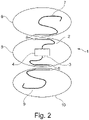
- FIG 2 A further exemplary embodiment of the antenna system 1 is shown, with the first and second antenna structure 2 , 3 again being present in the first installation space 5 .
- the third antenna structure 7 is in turn capacitively coupled to the second antenna structure 2 in the second installation space 6, in which case, in addition to the exemplary embodiment according to FIG figure 1
- a fourth antenna structure 9 is also capacitively coupled to the second antenna structure 3 and this fourth antenna structure 9 is located in a third installation space 10 .
- the capacitive coupling of the antenna structures 2, 7 and 3, 9 takes place via the coupling means 8, which can be designed in the same way or differently from one another.
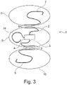
- the embodiment according to figure 3 based on the embodiment according to figure 2 , A fifth antenna structure 11 being connected to the interface 4 in the first installation space 5 .
- the coupling means 8 are of the same design, although it is also conceivable to design them differently.
- an end region of the antenna structures to be capacitively coupled to one another is designed and arranged to run parallel to one another, as is shown in FIGS Figures 1 to 3 is shown.
- the capacitive coupling it is also conceivable for the capacitive coupling to be implemented on the basis of other geometric shapes of the end region, such as, for example, a rectangular, triangular or wave-shaped toothing.
- FIG 1 are two spaces 5, 6 and in the figures 2 and 3 three different installation spaces 5, 6 and 10 are shown.
- these installation spaces 5, 6, 10 are located in a single component of the vehicle. So the in the figures 1 , 2 or 3
- the antenna structures shown can all be arranged in this single component, such as a front spoiler, a rear spoiler, a roof spoiler, a plastic boot lid or the like of the vehicle.
- At least two of the installation spaces 5, 6 or all three installation spaces 5, 6, 10 are located in different components of the vehicle.
- at least one of the antenna structures can be arranged in a plastic trunk lid and the at least one further antenna structure can be provided in a rear spoiler that is mounted adjacent to the plastic trunk lid. It is important and essential that when antenna structures are located in different components of the vehicle, they are arranged close to one another.
- a particularly advantageous embodiment for the capacitive coupling is achieved through the position of the two different components of the vehicle.
- one of the two antenna structures can also be arranged in or on a vehicle window, with another component being available adjacent thereto, in which the at least one further antenna structure is arranged.
- This can be, for example, a combination of rear sliding/plastic boot lid, windscreen/outside mirror, front spoiler/plastic bonnet, rear player/plastic boot lid or the like.
- the two different components with the installation spaces in which the respective antenna structures are arranged are arranged in a fixed manner relative to one another (such as, for example, accommodation of an antenna structure in a roof antenna which is arranged in a fixed manner in relation to a rear window or a roof spoiler).
- the two different components of the vehicle with their antenna structures can move relative to one another (such as in the combination of rear window/plastic trunk lid, windshield/exterior mirror, plastic trunk lid/rear spoiler, front spoiler/plastic bonnet and the like).
Landscapes
- Support Of Aerials (AREA)
- Details Of Aerials (AREA)
Description
- Die Erfindung betrifft ein Antennensystem, aufweisend eine erste Antennenstruktur und zumindest eine weitere Antennenstruktur, die an einem Kopplungsmittel angeschlossen sind, wobei die Antennenstrukturen dazu geeignet und ausgebildet sind, hochfrequente Signale zu empfangen und/oder auszusenden, gemäß den Merkmalen des Oberbegriffes des Patentanspruches 1.
- Zwei solcher bekannten Antennensysteme sind in den
Figuren 4 und 5 beschrieben. -
Figur 4 zeigt ein Antennensystem 41, das eine erste Antennenstruktur 42 und eine zweite Antennenstruktur 43 aufweist, die an einer gemeinsamen Schnittstelle 44 angeschlossen sind. Diese Elemente 42, 43 und 44 sind in einem gemeinsamen Bauraum 45, zum Beispiel eines Fahrzeuges, angeordnet. Dieser Bauraum kann zum Beispiel ein Spoiler, ein Stoßfänger, ein Kunststoffheckdeckel oder ein anderes Bauteil des Fahrzeuges aus einem elektrisch nicht leitfähigen Material sein. -
Figur 5 zeigt ein vergleichbares Antennensystem 51, ebenfalls mit einer ersten und zweiten Antennenstruktur 52, 53. Im Gegensatz zu dem Stand der Technik nach Figur 4 ist hier jede Antennenstruktur 52, 53 an einer eigenen Schnittstelle 54 angeschlossen. Auch diese Elemente sind wiederum in einem gemeinsamen Bauraum 55 angeordnet. - Die
EP 2 466 684 A1 beschreibt ein Diversitätsantennensystem mit einer Massenebene, auf der mindestens zwei strahlende Elemente und eine Neutralisationsleitung angeordnet sind. Die Neutralisationsleitung weist mindestens eine aktive Komponente auf. - Die
US 2013/0016024 A1 beschreibt ein Antennensystem mit mehreren Antennen und mindestens einem parasitären Element. Das parasitäre Element ist zwischen den Antennen angeordnet. - Bei Fahrzeugen, welche aufgrund ihrer Bauart über Bauteile aus elektrisch nicht leitfähigen Materialien (wie zum Beispiel Kunststoff) verfügen, wird dieser Bauraum oftmals dafür verwendet, andere technische Funktionalitäten, je nach Eignung des Anbauortes am Fahrzeug für diese weiteren Funktionalitäten, in diesen zu integrieren.
- Bekannt ist auch, dass in solchen Bauteilen wie Spoiler oder Kunststoffheckdeckel, Antennen für das Empfangen und/oder Aussenden von hochfrequenten elektromagnetischen Wellen (zum Beispiel für den Radioempfang) verbaut werden. Des weiteren ist es bekannt, dass zur Verbesserung der Empfangs- bzw. Sendequalität sogenannter fahrzeugintegrierter Antennensysteme mehr als eine Antenne für ein und den selben Dienst (zum Beispiel Radioempfang) zum Aufbau eines Diversity-Systems verwendet wird.
- Ein wesentliches Qualitäts- bzw. Bewertungsmerkmal eines solchen Diversity-Systems ist die sogenannten Diversity-Effizienz, welche ein Maß für die Qualitätsverbesserung des Sende- und/oder Empfangsverhaltens ist, welches durch den Einsatz von zwei oder auch mehr als zwei Antennenstrukturen (auch einfach als Antennen bezeichnet) erreicht wird. Dieser Wert wird im Allgemeinen durch Feldtests der im Fahrzeug integrierten Antennen messtechnisch ermittelt. Während der Entwicklungsphase eines Diversity-Systems (Mehrantennensystem) ergibt sich ein wesentlicher Hinweis auf die im Feldtest zu erwartende Diversity-Effizienz aus der paarweisen Berechnung der Korrelation der - nach Betrag und Phase - über den Azimut im stationären elektrischen Fernfeld erfassten Fußpunktspannungen der am Diversity-System beteiligten Antennenstrukturen. Je geringer die so berechnete Korrelation ist, desto größer ist die zu erwartende Diversity-Effizienz.
- Eine notwendige Bedingung, um die Korrelation der Antennenstrukturen niedrig zu halten, ist, dass deren Antennenwirkflächen von einander elektrisch entkoppelt sind. Dies wird üblicherweise durch eine räumliche Trennung der Antennen erreicht (siehe
Figuren 4 und 5 ). Da der notwendige Abstand zwischen den Antennenstrukturen mit zunehmender Wellenlänge bzw. sinkender Frequenz dazu größer werden muss, ist es nach dem Stand der Technik nicht möglich, eine ausreichend gute Dekorrelation in relativ zur Wellenlänge beengten Fahrzeugbauräumen zwischen zwei oder sogar mehreren Antennenstrukturen zu erzielen. Daher ist es dann notwendig, die Antennenstrukturen des Diversity-Systems über mehrere Bauräume des Fahrzeuges zu verteilen, die einen ausreichend großen Abstand zu einander haben müssen. Dies gilt insbesondere für die zwei benötigten Antennen für den UKW-Empfang des, nach aktuellem Stand der Technik, verwendeten Phasen-Diversitys, welche Wellenlängen von bis zu vier Meter Länge empfangen sollen. Daher ist es erforderlich, die ausreichend große Beabstandung der zumindest beiden Bauräume zueinander dadurch zu realisieren, dass zumindest eine Antennenstruktur in einem Frontspoiler oder Front-Stoßfänger und analog dazu die zweite Antennenstruktur in einem Heckspoiler bzw. Heck-Stoßfänger angeordnet wird. Da zumindest diese beiden weit von einander entfernten Antennenstrukturen über eine Schnittstelle miteinander verbunden werden müssen, um die beispielsweise empfangenen hochfrequenten Signale einem angeschlossenen Wiedergabegerät zuführen zu können, ist ein hoher Verkabelungsaufwand in nachteiliger Weise erforderlich. Das bedeutet, dass für eine ausreichend gute Dekorrelation relativ zur Wellenlänge der Nachteil gegeben ist, dass die Fußpunkte der Antennenstrukturen weit auseinander liegen. Dies hat weiterhin in nachteiliger Weise zur Folge, dass damit auch die, den Antennenstrukturen üblicherweise auf möglichst kurzem Weg nachzuschaltenden, in aktiven Antennensystemen eingesetzten Antennenverstärker (ein Beispiel für die Schnittstelle) weit auseinander liegen. Über die Notwendigkeit bei einem Diversity-System hinaus, mehrere Verstärker zu verwenden, ist auch ein zusätzlicher Aufwand für die Hochfrequenzverkabelung erforderlich, um die Signale im Fahrzeug wieder auf eine gemeinsame Schnittstelle des Diversity-Systems zu führen. - Analog den vorstehend gemachten Überlegungen zum UKW-Empfang gelten, mit entsprechend verkürzten Abständen zur elektrischen Entkopplung zwischen den Antennenstrukturen, die selben nachteiligen Überlegungen für die Dienste mit kürzeren Wellenlängen bzw. Nutzfrequenzen, wie zum Beispiel für den DAB- und TV-Empfang.
- Der Erfindung liegt daher die Aufgabe zugrunde, ein gattungsgemäßes Antennensystem dahingehend zu verbessern, dass die eingangs geschilderten Nachteile vermieden werden. Insbesondere soll eine möglichst gute Dekorrelation erzielt werden, um zu einer signifikanten Verbesserung der Sende- und/oder Empfangsleistung des Antennensystems zu kommen.
- Diese Aufgabe ist durch die Merkmale des Patentanspruches 1 gelöst.
- Erfindungsgemäß ist vorgesehen, dass zumindest an der in einem ersten Bauraum angeordneten ersten Antennenstruktur kapazitiv eine weitere in einem weiteren Bauraum angeordnete Antennenstruktur angekoppelt ist. Das bedeutet, dass zumindest zwei Antennenstrukturen eines Diversity-Systems vorgesehen sind, die den Frequenzbereich für einen oder mehrere Dienste (zum Beispiel Radio, TV, oder dergleichen) abdecken und in einem ersten gemeinsamen Bauraum, zum Beispiel einem Dachspoiler, einem Kunststoffheckdeckel oder dergleichen, eingebaut sind. Zunächst ermöglicht dieser erste gemeinsame Bauraum es nicht, eine ausreichende Dekorrelation zwischen diesen beiden Antennenstrukturen zu erzielen. Daher wird in vorteilhafter Weise eine ausreichende Dekorrelation der beiden Antennenstrukturen dadurch erreicht, dass die zumindest erste Antennenstruktur so ausgeführt wird, dass sie an eine zum Empfangen oder Aussenden elektromagnetischer Wellen geeignete weitere Antennenstruktur eines weiteren Bauraumes kapazitiv gekoppelt wird, wobei die zweite Antennenstruktur des ersten Bauraumes so ausgeführt ist, dass diese nicht an die kapazitiv an die erste Antennenstruktur angekoppelte weitere Antennenstruktur in dem weiteren Bauraum koppelt.
- In Weiterbildung der Erfindung ist vorgesehen, dass in den ersten Bauraum eine zweite Antennenstruktur angeordnet ist und an der in diesem ersten Bauraum angeordneten zweiten Antennenstruktur kapazitiv eine weitere in einem weiteren Bauraum angeordnete Antennenstruktur angekoppelt ist. Dadurch stehen in einem ersten Bauraum zwei Antennenstrukturen zur Verfügung, wobei an jeder dieser Antennenstrukturen eine weitere Antennenstruktur kapazitiv angekoppelt ist. Auch hierdurch wird eine Verbesserung der Dekorrelation erreicht, indem zumindest zwei Antennenstrukturen in einem ersten gemeinsamen Bauraum angeordnet sind und in davon abweichenden Bauräumen weitere Antennenstrukturen mit den beiden in dem ersten Bauraum angeordneten Antennenstrukturen kapazitiv gekoppelt sind. Dabei ist darauf zu achten, dass die Anordnung und Auslegung der kapazitiv angekoppelten Antennenstrukturen des zweiten bzw. des weiteren Bauraumes nicht untereinander verkoppelt sind. Dadurch lässt sich ein Diversity-Antennensystem mit zumindest zwei Antennenstrukturen hinsichtlich ihrer Dekorrelation deutlich verbessern, sodass es in vorteilhafter Weise zu einer signifikanten Verbesserung der Sende- und/oder Empfangsleistung des Antennensystems kommt. In Weiterbildung der Erfindung ist in dem ersten Bauraum zumindest eine weitere Antennenstruktur angeordnet. Das bedeutet, dass in dem ersten Bauraum zumindest drei, gegebenenfalls auch vier, fünf oder noch mehr Antennenstrukturen an der gemeinsamen Schnittstelle angeschlossen sind und hochfrequente Signale senden und/oder aussenden können. Dadurch lassen sich die Diversity-Eigenschaften des Antennensystems weiter verbessern, da gleichartige oder von einander unterschiedliche Antennenstrukturen in diesem Bauraum an unterschiedlichen Stellen in diesem Bauraum angeordnet sind und dadurch unterschiedliche Empfangseigenschaften haben. Diese unterschiedlichen Empfangseigenschaften können in an sich bekannter Weise bewertet werden und diejenige Antennenstruktur mit den besten Empfangseigenschaften für den wiederzugebenden Dienst ausgewählt werden.
- Verschiedene Ausführungsformen eines vorstehend beschriebenen erfindungsgemäßen Antennensystems werden im Folgenden anhand der
Figuren 1 bis 3 erläutert. DieFigur 1 zeigt, soweit im Einzelnen dargestellt, ein Antennensystem 1, welches eine erste Antennenstruktur 2 und eine zweite Antennenstruktur 3 aufweist. Elektromagnetische Wellen, die über diese Strukturen 2, 3 ausgesendet werden sollen, werden diesen beiden Antennenstrukturen 2, 3 über eine Schnittstelle zugeführt. Alternativ oder ergänzend dazu erfolgt über die Schnittstelle 4 die Weiterleitung der über die Antennenstrukturen 2, 3 empfangenen elektromagnetischen Wellen an ein hier nicht dargestelltes Wiedergabegerät. Die Schnittstelle 4 kann ein Verstärker sein, aber auch ein Frequenzwandler, der die elektromagnetischen Wellen von dem Hochfrequenzbereich in einen zwischenfrequenten bzw. niederfrequenten Bereich (oder umgekehrt) umsetzt. - Während die erste und zwei Antennenstruktur 2, 3 in einem ersten Bauraum 5 angeordnet sind, ist ein zweiter Bauraum 6 vorhanden, in dem eine dritte Antennenstruktur 7 angeordnet ist. Aufgrund der kapazitiven Ankopplung der dritten Antennenstruktur 7 an die erste Antennenstruktur 2 ist es möglich, diese beiden Antennenstrukturen 2, 7 nahe beieinander anzuordnen, gleichzeitig jedoch die Dekorrelation zu verbessern. Das bedeutet, dass die beiden Antennenstrukturen 2, 7 räumlich getrennt sind, um sie elektrisch zu entkoppeln.
- Die beiden Antennenstrukturen 2, 7 in
Figur 1 sind über Kopplungsmittel 8 kapazitiv aneinander angekoppelt. - In
Figur 2 ist ein weiteres Ausführungsbeispiel des Antennensystems 1 gezeigt, wobei wiederum in dem ersten Bauraum 5 die erste und zweite Antennenstruktur 2, 3 vorhanden sind. Bei diesem Ausführungsbeispiel ist wiederum an die zweite Antennenstruktur 2 die dritte Antennenstruktur 7 in dem zweiten Bauraum 6 kapazitiv angekoppelt, wobei zusätzlich gegenüber dem Ausführungsbeispiel gemäßFigur 1 auch an der zweiten Antennenstruktur 3 eine vierte Antennenstruktur 9 kapazitiv angekoppelt ist und sich diese vierte Antennenstruktur 9 in einem dritten Bauraum 10 befindet. Auch hier erfolgt die kapazitive Ankopplung der Antennenstrukturen 2, 7 und 3, 9 über die Kopplungsmittel 8, die gleichartig oder von einander unterschiedlich ausgebildet sein können. - Das Ausführungsbeispiel gemäß
Figur 3 basiert auf dem Ausführungsbeispiel gemäßFigur 2 , wobei an der Schnittstelle 4 in dem ersten Bauraum 5 eine fünfte Antennenstruktur 11 angeschlossen ist. Auch hier sind die Kopplungsmittel 8 gleichartig ausgebildet, wobei es denkbar ist, diese auch unterschiedlich auszuführen. - Zur Vereinfachung der Ausgestaltung der Kopplungsmittel 8 ist es denkbar, dass ein Endbereich der miteinander kapazitiv zu koppelnden Antennenstrukturen parallel zueinander verlaufend ausgebildet und angeordnet ist, wie dies in den
Figuren 1 bis 3 dargestellt ist. Es ist jedoch auch denkbar, die kapazitive Kopplung aufgrund anderer geometrischer Formen des Endbereiches zur realisieren, wie zum Beispiel einer rechteck- oder dreieckförmigen oder wellenförmigen Verzahnung. - In
Figur 1 sind zwei Bauräume 5, 6 und in denFiguren 2 und3 drei voneinander unterschiedliche Bauräume 5, 6 und 10 dargestellt. Hier ist es denkbar, dass sich diese Bauräume 5, 6, 10 in einem einzigen Bauteil des Fahrzeuges befinden. So können die in denFiguren 1 ,2 oder3 dargestellten Antennenstrukturen allesamt in diesem einzigen Bauteil, wie zum Beispiel einem Frontspoiler, einem Heckspoiler, einem Dachspoiler, einem Kunststoffheckdeckel oder dergleichen des Fahrzeuges angeordnet sein. - Alternativ dazu ist es denkbar, dass zumindest zwei der Bauräume 5, 6 oder auch alle drei Bauräume 5, 6, 10 sich in unterschiedlichen Bauteilen des Fahrzeuges befinden. So kann beispielsweise zumindest eine der Antennenstrukturen in einem Kunststoffheckdeckel angeordnet sein und die zumindest eine weitere Antennenstruktur in einem Heckspoiler vorgesehen werden, der auf dem Kunststoffheckdeckel benachbart montiert ist. Wichtig und wesentlich ist es, dass dann, wenn sich Antennenstrukturen in unterschiedlichen Bauteilen des Fahrzeuges befinden, diese nah zueinander angeordnet sind.
- Eine besonders vorteilhafte Ausgestaltung für die kapazitive Kopplung wird durch die Lage der beiden unterschiedlichen Bauteile des Fahrzeuges erzielt. So kann beispielsweise eine der beiden Antennenstrukturen auch in oder auf einer Fahrzeugscheibe angeordnet werden, wobei benachbart dazu ein anderes Bauteil zur Verfügung steht, in dem die zumindest eine weitere Antennenstruktur angeordnet wird. Hierbei kann es sich beispielsweise um die Kombination Heckschiebe/Kunststoffheckdeckel, Frontscheibe/Außenspiegel, Frontspoiler/Kunststoffmotorhaube, Heckspieler/Kunststoffheckdeckel oder dergleichen handeln. Dabei ist auch daran zu denken, dass die beiden unterschiedlichen Bauteile mit den Bauräumen, in denen die jeweiligen Antennenstrukturen angeordnet sind, ortsfest zueinander angeordnet sind (wie zum Beispiel Unterbringung einer Antennenstruktur in einer Dachantenne, die ortsfest zu einer Heckscheibe oder einem Dachspoiler angeordnet ist) untergebracht werden. Alternativ dazu ist es denkbar, dass sich die beiden unterschiedlichen Bauteile des Fahrzeuges mit ihren Antennenstrukturen relativ zueinander bewegen können (wie beispielsweise bei der Kombination Heckscheibe/Kunststoffheckdeckel, Frontscheibe/Außenspiegel, Kunststoffheckdeckel/Heckspoiler, Frontspoiler/Kunststoffmotorhaube und dergleichen).
-
- 1.
- Antennensystem
- 2.
- Erste Antennenstruktur
- 3.
- Zweite Antennenstruktur
- 4.
- Schnittstelle
- 5.
- Erster Bauraum
- 6.
- Zweiter Bauraum
- 7.
- Dritte Antennenstruktur
- 8.
- Kopplungsmittel
- 9.
- Vierte Antennenstruktur
- 10.
- Dritter Bauraum
- 11.
- Fünfte Antennenstruktur
- 41.
- Antennensystem
- 42.
- Erste Antennenstruktur
- 43.
- Zweite Antennenstruktur
- 44.
- Schnittstelle
- 45.
- gemeinsamer Bauraum
- 51.
- Antennensystem
- 52.
- Erste Antennenstruktur
- 53.
- Zweite Antennenstruktur
- 54.
- Schnittstelle
- 55.
- gemeinsamer Bauraum
Claims (8)
- Antennensystem (1), aufweisend eine erste Antennenstruktur (2) und eine zweite Antennenstruktur (3), die an einer Schnittstelle (4) angeschlossen sind, wobei die Antennenstrukturen (2, 3) dazu geeignet und ausgebildet sind, hochfrequente Signale zu empfangen und/oder auszusenden, wobei die erste Antennenstruktur (2) und die zweite Antennenstruktur (3) in einem ersten Bauraum (5) angeordnet sind, dadurch gekennzeichnet, dass an der ersten Antennenstruktur (2) kapazitiv eine in einem zweiten Bauraum (6) angeordnete dritte Antennenstruktur (7) angekoppelt ist, wobei die zweite Antennenstruktur (3) nicht an die dritte Antennenstruktur (7) angekoppelt ist.
- Antennensystem (1) nach Anspruch 1, dadurch gekennzeichnet, dass an der zweiten Antennenstruktur (3) kapazitiv eine in einem dritten Bauraum (10) angeordnete vierte Antennenstruktur (9) angekoppelt ist.
- Antennensystem (1) nach Anspruch 1 oder 2, dadurch gekennzeichnet, dass in dem ersten Bauraum (5) zumindest eine weitere Antennenstruktur (11) angeordnet ist.
- Antennensystem (1) nach einem der vorgehenden Ansprüche, dadurch gekennzeichnet, dass ein Endbereich der miteinander kapazitiv zu koppelnden Antennenstrukturen parallel zueinander verlaufend ausgebildet und angeordnet ist.
- Fahrzeug, aufweisend ein Antennensystem (1) nach einem der vorgehenden Ansprüche.
- Fahrzeug nach Anspruch 5, dadurch gekennzeichnet, dass sich die Bauräume (5, 6, 10) in einem Bauteil des Fahrzeuges befinden.
- Fahrzeug nach Anspruch 5, dadurch gekennzeichnet, dass zumindest zwei der Bauräume (5, 6, 10) sich in unterschiedlichen Bauteilen des Fahrzeuges befinden.
- Fahrzeug nach Anspruch 7, dadurch gekennzeichnet, dass die kapazitive Kopplung durch die Lage der beiden unterschiedlichen Bauteile des Fahrzeuges erfolgt.
Applications Claiming Priority (2)
| Application Number | Priority Date | Filing Date | Title |
|---|---|---|---|
| DE102014205764 | 2014-03-27 | ||
| PCT/EP2015/056639 WO2015144849A1 (de) | 2014-03-27 | 2015-03-26 | Antennensystem mit verbesserter dekorrelation |
Publications (2)
| Publication Number | Publication Date |
|---|---|
| EP3123560A1 EP3123560A1 (de) | 2017-02-01 |
| EP3123560B1 true EP3123560B1 (de) | 2022-08-10 |
Family
ID=52774234
Family Applications (1)
| Application Number | Title | Priority Date | Filing Date |
|---|---|---|---|
| EP15712900.8A Active EP3123560B1 (de) | 2014-03-27 | 2015-03-26 | Antennensystem mit verbesserter dekorrelation |
Country Status (3)
| Country | Link |
|---|---|
| EP (1) | EP3123560B1 (de) |
| DE (1) | DE102015205550A1 (de) |
| WO (1) | WO2015144849A1 (de) |
Citations (1)
| Publication number | Priority date | Publication date | Assignee | Title |
|---|---|---|---|---|
| US20130016024A1 (en) * | 2011-07-13 | 2013-01-17 | Qualcomm Incorporated | Wideband antenna system with multiple antennas and at least one parasitic element |
Family Cites Families (1)
| Publication number | Priority date | Publication date | Assignee | Title |
|---|---|---|---|---|
| FR2968845B1 (fr) * | 2010-12-14 | 2013-01-11 | Centre Nat Rech Scient | Systeme d'antenne en diversite |
-
2015
- 2015-03-26 DE DE102015205550.7A patent/DE102015205550A1/de not_active Ceased
- 2015-03-26 EP EP15712900.8A patent/EP3123560B1/de active Active
- 2015-03-26 WO PCT/EP2015/056639 patent/WO2015144849A1/de not_active Ceased
Patent Citations (1)
| Publication number | Priority date | Publication date | Assignee | Title |
|---|---|---|---|---|
| US20130016024A1 (en) * | 2011-07-13 | 2013-01-17 | Qualcomm Incorporated | Wideband antenna system with multiple antennas and at least one parasitic element |
Also Published As
| Publication number | Publication date |
|---|---|
| EP3123560A1 (de) | 2017-02-01 |
| WO2015144849A1 (de) | 2015-10-01 |
| DE102015205550A1 (de) | 2015-10-01 |
Similar Documents
| Publication | Publication Date | Title |
|---|---|---|
| DE102006025176B4 (de) | Antennenmodul für ein Fahrzeug | |
| DE102009051605B4 (de) | Hochintegrierte Multiband-Finnenantenne für ein Fahrzeug | |
| EP0514380B1 (de) | Antennenkombination | |
| DE112018004509T5 (de) | In fahrzeugkarosserie eingebettete antennenvorrichtung | |
| DE102016100126A1 (de) | In eine Fahrzeugkarosserieverkleidung eingebaute Schlitzantenne | |
| DE102016007265A1 (de) | Array-Antenne und Radarsystem für Fahrzeuge, das diese aufweist | |
| DE102009038150A1 (de) | Multiband-Antennenmodul für ein Fahrzeug | |
| DE102012210314A1 (de) | Antennenanordnung und Verfahren | |
| DE102004046634A1 (de) | Antennenradarsystem und Verfahren zu seinem Betrieb | |
| DE102014222837A1 (de) | Radarsystem | |
| DE202013007872U1 (de) | Mehrfachband-Finnenantenne für den mobilen Einsatz, insbesondere für Fahrzeuge | |
| WO2016045830A1 (de) | Antenne für nahbereichsradar | |
| DE102012224062A1 (de) | Streifenleiterantenne, Gruppenantenne und Radarvorrichtung | |
| DE102009038038A1 (de) | Antennenanordnung für ein Kraftfahrzeug und Kraftfahrzeug | |
| DE10331213B4 (de) | Scheibenantenne für den LMK- und diversitären FM-Empfang mobiler Kraftfahrzeuge | |
| EP1698019B1 (de) | Fahrzeugscheibenantenne | |
| EP0325946A1 (de) | Antennensystem für den Rundfunk-Empfang in Kraftfahrzeugen | |
| DE112013004323T5 (de) | Drahtloskommunikationsvorrichtung | |
| EP0935825B1 (de) | Kraftfahrzeug-radarsensor | |
| DE102014016851B3 (de) | MIMO Schlitzantenne für Kraftfahrzeuge | |
| EP1327284B1 (de) | Stossfängerantennenanordnung | |
| DE102016215437A1 (de) | Radarsensoreinrichtung für ein Kraftfahrzeug, Kraftfahrzeug und Verfahren zum Betreiben einer Radarsensoreinrichtung eines Kraftfahrzeugs | |
| DE102015205550A1 (de) | Antennensystem mit verbesserter Dekorrelation | |
| DE102008000502A1 (de) | Radarsensor mit Patch-Antenne für Kraftfahrzeuge | |
| DE112011103826T5 (de) | Beweglicher Körper, ausgestattet mit einer Antennenvorrichtung |
Legal Events
| Date | Code | Title | Description |
|---|---|---|---|
| STAA | Information on the status of an ep patent application or granted ep patent |
Free format text: STATUS: THE INTERNATIONAL PUBLICATION HAS BEEN MADE |
|
| PUAI | Public reference made under article 153(3) epc to a published international application that has entered the european phase |
Free format text: ORIGINAL CODE: 0009012 |
|
| STAA | Information on the status of an ep patent application or granted ep patent |
Free format text: STATUS: REQUEST FOR EXAMINATION WAS MADE |
|
| 17P | Request for examination filed |
Effective date: 20160826 |
|
| AK | Designated contracting states |
Kind code of ref document: A1 Designated state(s): AL AT BE BG CH CY CZ DE DK EE ES FI FR GB GR HR HU IE IS IT LI LT LU LV MC MK MT NL NO PL PT RO RS SE SI SK SM TR |
|
| AX | Request for extension of the european patent |
Extension state: BA ME |
|
| DAV | Request for validation of the european patent (deleted) | ||
| DAX | Request for extension of the european patent (deleted) | ||
| STAA | Information on the status of an ep patent application or granted ep patent |
Free format text: STATUS: EXAMINATION IS IN PROGRESS |
|
| 17Q | First examination report despatched |
Effective date: 20200103 |
|
| GRAP | Despatch of communication of intention to grant a patent |
Free format text: ORIGINAL CODE: EPIDOSNIGR1 |
|
| STAA | Information on the status of an ep patent application or granted ep patent |
Free format text: STATUS: GRANT OF PATENT IS INTENDED |
|
| GRAS | Grant fee paid |
Free format text: ORIGINAL CODE: EPIDOSNIGR3 |
|
| INTG | Intention to grant announced |
Effective date: 20220317 |
|
| GRAA | (expected) grant |
Free format text: ORIGINAL CODE: 0009210 |
|
| STAA | Information on the status of an ep patent application or granted ep patent |
Free format text: STATUS: THE PATENT HAS BEEN GRANTED |
|
| AK | Designated contracting states |
Kind code of ref document: B1 Designated state(s): AL AT BE BG CH CY CZ DE DK EE ES FI FR GB GR HR HU IE IS IT LI LT LU LV MC MK MT NL NO PL PT RO RS SE SI SK SM TR |
|
| REG | Reference to a national code |
Ref country code: AT Ref legal event code: REF Ref document number: 1511237 Country of ref document: AT Kind code of ref document: T Effective date: 20220815 Ref country code: CH Ref legal event code: EP |
|
| REG | Reference to a national code |
Ref country code: IE Ref legal event code: FG4D Free format text: LANGUAGE OF EP DOCUMENT: GERMAN |
|
| REG | Reference to a national code |
Ref country code: DE Ref legal event code: R096 Ref document number: 502015015997 Country of ref document: DE |
|
| REG | Reference to a national code |
Ref country code: NL Ref legal event code: MP Effective date: 20220810 |
|
| REG | Reference to a national code |
Ref country code: LT Ref legal event code: MG9D |
|
| PG25 | Lapsed in a contracting state [announced via postgrant information from national office to epo] |
Ref country code: SE Free format text: LAPSE BECAUSE OF FAILURE TO SUBMIT A TRANSLATION OF THE DESCRIPTION OR TO PAY THE FEE WITHIN THE PRESCRIBED TIME-LIMIT Effective date: 20220810 Ref country code: RS Free format text: LAPSE BECAUSE OF FAILURE TO SUBMIT A TRANSLATION OF THE DESCRIPTION OR TO PAY THE FEE WITHIN THE PRESCRIBED TIME-LIMIT Effective date: 20220810 Ref country code: PT Free format text: LAPSE BECAUSE OF FAILURE TO SUBMIT A TRANSLATION OF THE DESCRIPTION OR TO PAY THE FEE WITHIN THE PRESCRIBED TIME-LIMIT Effective date: 20221212 Ref country code: NO Free format text: LAPSE BECAUSE OF FAILURE TO SUBMIT A TRANSLATION OF THE DESCRIPTION OR TO PAY THE FEE WITHIN THE PRESCRIBED TIME-LIMIT Effective date: 20221110 Ref country code: NL Free format text: LAPSE BECAUSE OF FAILURE TO SUBMIT A TRANSLATION OF THE DESCRIPTION OR TO PAY THE FEE WITHIN THE PRESCRIBED TIME-LIMIT Effective date: 20220810 Ref country code: LV Free format text: LAPSE BECAUSE OF FAILURE TO SUBMIT A TRANSLATION OF THE DESCRIPTION OR TO PAY THE FEE WITHIN THE PRESCRIBED TIME-LIMIT Effective date: 20220810 Ref country code: LT Free format text: LAPSE BECAUSE OF FAILURE TO SUBMIT A TRANSLATION OF THE DESCRIPTION OR TO PAY THE FEE WITHIN THE PRESCRIBED TIME-LIMIT Effective date: 20220810 Ref country code: FI Free format text: LAPSE BECAUSE OF FAILURE TO SUBMIT A TRANSLATION OF THE DESCRIPTION OR TO PAY THE FEE WITHIN THE PRESCRIBED TIME-LIMIT Effective date: 20220810 Ref country code: ES Free format text: LAPSE BECAUSE OF FAILURE TO SUBMIT A TRANSLATION OF THE DESCRIPTION OR TO PAY THE FEE WITHIN THE PRESCRIBED TIME-LIMIT Effective date: 20220810 |
|
| PG25 | Lapsed in a contracting state [announced via postgrant information from national office to epo] |
Ref country code: PL Free format text: LAPSE BECAUSE OF FAILURE TO SUBMIT A TRANSLATION OF THE DESCRIPTION OR TO PAY THE FEE WITHIN THE PRESCRIBED TIME-LIMIT Effective date: 20220810 Ref country code: IS Free format text: LAPSE BECAUSE OF FAILURE TO SUBMIT A TRANSLATION OF THE DESCRIPTION OR TO PAY THE FEE WITHIN THE PRESCRIBED TIME-LIMIT Effective date: 20221210 Ref country code: HR Free format text: LAPSE BECAUSE OF FAILURE TO SUBMIT A TRANSLATION OF THE DESCRIPTION OR TO PAY THE FEE WITHIN THE PRESCRIBED TIME-LIMIT Effective date: 20220810 Ref country code: GR Free format text: LAPSE BECAUSE OF FAILURE TO SUBMIT A TRANSLATION OF THE DESCRIPTION OR TO PAY THE FEE WITHIN THE PRESCRIBED TIME-LIMIT Effective date: 20221111 |
|
| PG25 | Lapsed in a contracting state [announced via postgrant information from national office to epo] |
Ref country code: SM Free format text: LAPSE BECAUSE OF FAILURE TO SUBMIT A TRANSLATION OF THE DESCRIPTION OR TO PAY THE FEE WITHIN THE PRESCRIBED TIME-LIMIT Effective date: 20220810 Ref country code: RO Free format text: LAPSE BECAUSE OF FAILURE TO SUBMIT A TRANSLATION OF THE DESCRIPTION OR TO PAY THE FEE WITHIN THE PRESCRIBED TIME-LIMIT Effective date: 20220810 Ref country code: DK Free format text: LAPSE BECAUSE OF FAILURE TO SUBMIT A TRANSLATION OF THE DESCRIPTION OR TO PAY THE FEE WITHIN THE PRESCRIBED TIME-LIMIT Effective date: 20220810 Ref country code: CZ Free format text: LAPSE BECAUSE OF FAILURE TO SUBMIT A TRANSLATION OF THE DESCRIPTION OR TO PAY THE FEE WITHIN THE PRESCRIBED TIME-LIMIT Effective date: 20220810 |
|
| REG | Reference to a national code |
Ref country code: DE Ref legal event code: R097 Ref document number: 502015015997 Country of ref document: DE |
|
| PG25 | Lapsed in a contracting state [announced via postgrant information from national office to epo] |
Ref country code: SK Free format text: LAPSE BECAUSE OF FAILURE TO SUBMIT A TRANSLATION OF THE DESCRIPTION OR TO PAY THE FEE WITHIN THE PRESCRIBED TIME-LIMIT Effective date: 20220810 Ref country code: EE Free format text: LAPSE BECAUSE OF FAILURE TO SUBMIT A TRANSLATION OF THE DESCRIPTION OR TO PAY THE FEE WITHIN THE PRESCRIBED TIME-LIMIT Effective date: 20220810 |
|
| PLBE | No opposition filed within time limit |
Free format text: ORIGINAL CODE: 0009261 |
|
| STAA | Information on the status of an ep patent application or granted ep patent |
Free format text: STATUS: NO OPPOSITION FILED WITHIN TIME LIMIT |
|
| PG25 | Lapsed in a contracting state [announced via postgrant information from national office to epo] |
Ref country code: AL Free format text: LAPSE BECAUSE OF FAILURE TO SUBMIT A TRANSLATION OF THE DESCRIPTION OR TO PAY THE FEE WITHIN THE PRESCRIBED TIME-LIMIT Effective date: 20220810 |
|
| 26N | No opposition filed |
Effective date: 20230511 |
|
| PG25 | Lapsed in a contracting state [announced via postgrant information from national office to epo] |
Ref country code: SI Free format text: LAPSE BECAUSE OF FAILURE TO SUBMIT A TRANSLATION OF THE DESCRIPTION OR TO PAY THE FEE WITHIN THE PRESCRIBED TIME-LIMIT Effective date: 20220810 |
|
| PG25 | Lapsed in a contracting state [announced via postgrant information from national office to epo] |
Ref country code: MC Free format text: LAPSE BECAUSE OF FAILURE TO SUBMIT A TRANSLATION OF THE DESCRIPTION OR TO PAY THE FEE WITHIN THE PRESCRIBED TIME-LIMIT Effective date: 20220810 |
|
| REG | Reference to a national code |
Ref country code: CH Ref legal event code: PL |
|
| GBPC | Gb: european patent ceased through non-payment of renewal fee |
Effective date: 20230326 |
|
| REG | Reference to a national code |
Ref country code: BE Ref legal event code: MM Effective date: 20230331 |
|
| PG25 | Lapsed in a contracting state [announced via postgrant information from national office to epo] |
Ref country code: LU Free format text: LAPSE BECAUSE OF NON-PAYMENT OF DUE FEES Effective date: 20230326 |
|
| REG | Reference to a national code |
Ref country code: IE Ref legal event code: MM4A |
|
| PG25 | Lapsed in a contracting state [announced via postgrant information from national office to epo] |
Ref country code: GB Free format text: LAPSE BECAUSE OF NON-PAYMENT OF DUE FEES Effective date: 20230326 |
|
| PG25 | Lapsed in a contracting state [announced via postgrant information from national office to epo] |
Ref country code: LI Free format text: LAPSE BECAUSE OF NON-PAYMENT OF DUE FEES Effective date: 20230331 Ref country code: IE Free format text: LAPSE BECAUSE OF NON-PAYMENT OF DUE FEES Effective date: 20230326 Ref country code: GB Free format text: LAPSE BECAUSE OF NON-PAYMENT OF DUE FEES Effective date: 20230326 Ref country code: CH Free format text: LAPSE BECAUSE OF NON-PAYMENT OF DUE FEES Effective date: 20230331 |
|
| PG25 | Lapsed in a contracting state [announced via postgrant information from national office to epo] |
Ref country code: BE Free format text: LAPSE BECAUSE OF NON-PAYMENT OF DUE FEES Effective date: 20230331 |
|
| REG | Reference to a national code |
Ref country code: AT Ref legal event code: MM01 Ref document number: 1511237 Country of ref document: AT Kind code of ref document: T Effective date: 20230326 |
|
| PG25 | Lapsed in a contracting state [announced via postgrant information from national office to epo] |
Ref country code: AT Free format text: LAPSE BECAUSE OF NON-PAYMENT OF DUE FEES Effective date: 20230326 |
|
| PG25 | Lapsed in a contracting state [announced via postgrant information from national office to epo] |
Ref country code: AT Free format text: LAPSE BECAUSE OF NON-PAYMENT OF DUE FEES Effective date: 20230326 |
|
| PG25 | Lapsed in a contracting state [announced via postgrant information from national office to epo] |
Ref country code: BG Free format text: LAPSE BECAUSE OF FAILURE TO SUBMIT A TRANSLATION OF THE DESCRIPTION OR TO PAY THE FEE WITHIN THE PRESCRIBED TIME-LIMIT Effective date: 20220810 |
|
| PG25 | Lapsed in a contracting state [announced via postgrant information from national office to epo] |
Ref country code: BG Free format text: LAPSE BECAUSE OF FAILURE TO SUBMIT A TRANSLATION OF THE DESCRIPTION OR TO PAY THE FEE WITHIN THE PRESCRIBED TIME-LIMIT Effective date: 20220810 |
|
| PGFP | Annual fee paid to national office [announced via postgrant information from national office to epo] |
Ref country code: FR Payment date: 20250325 Year of fee payment: 11 |
|
| PGFP | Annual fee paid to national office [announced via postgrant information from national office to epo] |
Ref country code: IT Payment date: 20250319 Year of fee payment: 11 |
|
| PG25 | Lapsed in a contracting state [announced via postgrant information from national office to epo] |
Ref country code: CY Free format text: LAPSE BECAUSE OF FAILURE TO SUBMIT A TRANSLATION OF THE DESCRIPTION OR TO PAY THE FEE WITHIN THE PRESCRIBED TIME-LIMIT; INVALID AB INITIO Effective date: 20150326 |
|
| PG25 | Lapsed in a contracting state [announced via postgrant information from national office to epo] |
Ref country code: HU Free format text: LAPSE BECAUSE OF FAILURE TO SUBMIT A TRANSLATION OF THE DESCRIPTION OR TO PAY THE FEE WITHIN THE PRESCRIBED TIME-LIMIT; INVALID AB INITIO Effective date: 20150326 |
|
| PG25 | Lapsed in a contracting state [announced via postgrant information from national office to epo] |
Ref country code: TR Free format text: LAPSE BECAUSE OF FAILURE TO SUBMIT A TRANSLATION OF THE DESCRIPTION OR TO PAY THE FEE WITHIN THE PRESCRIBED TIME-LIMIT Effective date: 20220810 |
|
| PGFP | Annual fee paid to national office [announced via postgrant information from national office to epo] |
Ref country code: DE Payment date: 20260327 Year of fee payment: 12 |