EP3123232B1 - Verfahren und vorrichtungen zur erweiterten realität - Google Patents
Verfahren und vorrichtungen zur erweiterten realität Download PDFInfo
- Publication number
- EP3123232B1 EP3123232B1 EP15710532.1A EP15710532A EP3123232B1 EP 3123232 B1 EP3123232 B1 EP 3123232B1 EP 15710532 A EP15710532 A EP 15710532A EP 3123232 B1 EP3123232 B1 EP 3123232B1
- Authority
- EP
- European Patent Office
- Prior art keywords
- see
- filtering means
- wearer
- optical filtering
- loe
- Prior art date
- Legal status (The legal status is an assumption and is not a legal conclusion. Google has not performed a legal analysis and makes no representation as to the accuracy of the status listed.)
- Active
Links
Images
Classifications
-
- G—PHYSICS
- G02—OPTICS
- G02B—OPTICAL ELEMENTS, SYSTEMS OR APPARATUS
- G02B27/00—Optical systems or apparatus not provided for by any of the groups G02B1/00 - G02B26/00, G02B30/00
- G02B27/01—Head-up displays
- G02B27/017—Head mounted
- G02B27/0172—Head mounted characterised by optical features
-
- G—PHYSICS
- G02—OPTICS
- G02B—OPTICAL ELEMENTS, SYSTEMS OR APPARATUS
- G02B5/00—Optical elements other than lenses
- G02B5/20—Filters
- G02B5/22—Absorbing filters
-
- G—PHYSICS
- G02—OPTICS
- G02B—OPTICAL ELEMENTS, SYSTEMS OR APPARATUS
- G02B5/00—Optical elements other than lenses
- G02B5/20—Filters
- G02B5/28—Interference filters
-
- G—PHYSICS
- G02—OPTICS
- G02B—OPTICAL ELEMENTS, SYSTEMS OR APPARATUS
- G02B27/00—Optical systems or apparatus not provided for by any of the groups G02B1/00 - G02B26/00, G02B30/00
- G02B27/01—Head-up displays
- G02B27/017—Head mounted
- G02B27/0172—Head mounted characterised by optical features
- G02B2027/0174—Head mounted characterised by optical features holographic
-
- G—PHYSICS
- G02—OPTICS
- G02B—OPTICAL ELEMENTS, SYSTEMS OR APPARATUS
- G02B27/00—Optical systems or apparatus not provided for by any of the groups G02B1/00 - G02B26/00, G02B30/00
- G02B27/01—Head-up displays
- G02B27/017—Head mounted
- G02B2027/0178—Eyeglass type
Definitions
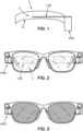
- the invention relates to see-through head-mounted devices for the display and visualization of computer-generated information content by a wearer.
- the invention further provides related uses of selective optical filtering means in the see-through head mounted device.
- Head-mounted devices with display features are known in the art.
- Such head-mounted display devices include so-called 'smart glasses', which allow the wearer thereof to visualize information such as images or text for augmented reality.
- JP 2013-200452 A relates to a polarizing lens having reflective effects and color balance when being worn, and also having high transmissivity.
- a reflective polarizer is provided outside an optical component of a laminate structure including a polarizer, and the transmission axis of the optical component including the polarizer and the transmission axis of the reflective polarizer become nearly the same.
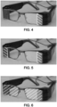
- Such devices raise issues of confidentiality of the information content displayed by the HMD. This is because persons other than the wearer may be in a position to view the information content displayed. Further, for aesthetic reasons, it is desirable that the HMD is designed in such a way that the display system is at least partially hidden from the view of an outside observer.
- the selective optical filtering means are capable of selectively reflecting incident light stemming from the wearer's environment, for example natural or artificial light.
- the selective optical filtering means comprise means selected from absorption and interference filters.
- the selective optical filtering means are capable of conferring a specific color to the see-though element, when visualized from the point of view of an outside observer.
- the selective optical filtering means are selectively provided for a specific surface area of the see-through element, for example according to spatial gradients, according to the location of the display system relative to the see-through element, and/or according to the incident light stemming from the wearer's environment.
- the selective optical filtering means are activable.
- the selective optical filtering means are spectrally controllable, preferably the selective optical filtering means are controlled by a synchronization with the emission spectrum of the light source of the display system.
- the selective optical filtering means are provided for one or both of the lenses, and preferably the display system is for monocular display.
- R1 ⁇ max R2;E
- R1 ⁇ max R2;E
- said incident light with a light intensity level superior or equal to that of the light emitted by the see-through element, with 5% ⁇ R1 ⁇ 97%.
- the present invention provides the use of selective optical filtering means in a see-through head mounted device for a wearer according to the invention as defined above.
- the HMD of the invention is a pair of eyeglasses, and comprises ophthalmic corrective lenses, such as prescription lenses.
- the selective optical filtering means e.g. high-reflection coating
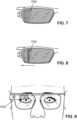
- the selective optical filtering means are provided in/on the lens in such a way that the LOE is situated between the eye of the wearer and the selective filtering means.
- the selective filtering means are disposed on the front surface of the lens, or between the embedded LOE and the front surface of the lens, including selective optical filtering means located on the outer front surface of the lens and/or selective optical filtering means located between the LOE and the outer front surface of the lens.
- the selective optical filtering means can comprise a dye and/or pigment configured to inhibit transmission by absorption.
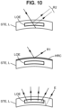
- the selective optical filtering means can comprise interferential filtering means configured to inhibit transmission of at least one (selected range of) wavelength(s) of incident light, incident on at least one zone of a surface of the see-through element, within a first selected range of angles of incidence.
- the interferential means may be an alternative to or in addition to absorptive filtering means.
- interferential filtering means rely on the Bragg theory, and can be selected from thin films, thick films, multilayers, Rugate structures, holography gratings, photonic crystals, liquid crystal technology, including cholesteric crystals and blue phases, etc. and combinations thereof.
- Cholesteric liquid crystals are liquid crystals with a helical structure. They are usually composed of nematic liquid crystals with a chiral dopant. Manufacturing methods are for instance disclosed in WO 2014/024764 or US 2002/113937 .
- Blue phase is a particular state appearing when cooling down chiral nematics from the isotropic state. Blue phase has a highly symmetric molecular structure. Methods of forming a liquid crystal blue phase are provided in TW 201336975 .
- the selective optical filtering means can be any optical filtering means that have an effect on whole or part of the visible range (380 - 780nm).
- the selectivity of the optical filtering means can refer to the spectral properties (wavelength/s) and/or to the angle of incidence of the light.
- the selective optical filtering means can be configured to selectively inhibit (block) transmission, through the see-through element, of at least one wavelength or at least one selected range of wavelengths of incident light in the visible light spectrum (or in any sub-spectrum thereof) at a suitable inhibition rate.
- suitable inhibition rates include rates of at least 30%, at least 25%, at least 20%, at least 15%, at least 10% or at least 5%.
- filtering means selectively inhibit" one wavelength or a range of wavelengths if the filtering means inhibit at least some transmission of one or more wavelengths within the range, while having little or no effect on the transmission of visible wavelengths outside the range, unless specifically configured to do so.
- rejection rate or inhibition rate or degree of inhibition refers to the percentage of incident light within one or more selected ranges of wavelengths which is prevented from being transmitted.
- the parameter range of wavelengths or bandwidth is defined as the Full Width at Half Maximum (FWHM).
- the selectivity can also be defined according to the angle of incidence of the wavelengths of interest.
- the selective optical filtering means can be configured to selectively inhibit transmission, through the see-through element, of at least one selected range of wavelengths of incident light in the visible light spectrum at a suitable inhibition rate, the selective optical filtering means being further configured to transmit at a suitable rate the incident light of the visible spectrum outside the at least one selected range of wavelengths, so that the see-through element retains see-through properties for the wearer.
- suitable inhibition rates include rates of at least 30%, at least 25%, at least 20%, at least 15%, at least 10% or at least 5%.
- suitable transmission rates include rates of at least 16%, at least 12%, at least 10%, at least 8%, or at least 3%.
- the selective optical filtering means can comprise first and second selective optical filtering means, the first selective optical filtering means being configured to inhibit a first range of wavelengths, and the second selective optical filtering means being configured to inhibit a second range of wavelengths having a bandwidth.
- a selective dual band filter is provided for selectively inhibiting light in a narrow band of wavelengths centered on a first wavelength; and in a narrow band of wavelengths centered on a second wavelength.
- the skilled person can determine suitable filtering means that are configured to at least partially hide the information content displayed by said display system from the view of an outside observer, while retaining see-through properties for the wearer's visual field. For example, based upon a given display system, the skilled person can determine the relevant wavelength(s) or range of wavelengths, and identify suitable selective optical filtering means, such as optical filter(s) that blocks at least one wavelength of the emission spectrum of the light source of the display system.
- Selective filtering means that can be activated upon command
- the selective optical filtering means are controllable in absorption, preferably the selective optical filtering means are controlled by a synchronization with the emission pattern and/or intensity of the light source of the display system.
- the selective optical filtering means When the selective optical filtering means are controllable in absorption, they can be controlled through synchronizing means. For example, synchronization can be performed with respect to the emission pattern and/or the intensity of the light source of the display system.
- the selective optical filtering means When the selective optical filtering means are spectrally controllable, they can be controlled through synchronizing means. For example, synchronization can be performed with respect to the emission spectrum of the light source of the display system.
- suitable filtering means can be implemented in a polymer-stabilized device. This can be achieved by taking into account the fact that the Bragg reflected color of a cholesteric liquid crystal (CLC) or blue phase can be switched to another one by applying an electric field on the polymer-stabilized device. This is advantageous, because it makes it possible to easily change the properties of the selective optical filtering means (here, change the reflected color of a selective mirror).
- CLC cholesteric liquid crystal
- the HMD comprises selective optical filtering means, configured to at least partially hide the display system of the HMD from the view of an outside observer, while retaining see-through properties for the wearer's visual field, and configured to at least partially hide the information displayed by display system from the view of an outside observer, while retaining see-through properties for the wearer's visual field.
- the selective optical means contribute to improving the aesthetics and/or the level of display confidentiality afforded by the HMD.
- the see-through element can comprise selective optical filtering means that are capable of conferring a specific color to the see-though element, when visualized from the point of view of an outside observer.
- the skilled person can identify and implement suitable selective means.
- the specific color can be conferred to one part or to the entirety of the see-though element.
- the see-through element comprises two ophthalmic lenses, the color can be conferred to one or both lenses.
- the selective optical filtering means can be selectively provided for a specific surface area of the see-through element.
- the filtering means can be applied according to spatial gradients to the see-through element, for example to the periphery or to one side of the see-through element such as the periphery or one or more edge(s) of the lens(es).
- the selective optical filtering means can be provided as a function of the location of the display system relative to the see-through element in the HMD, and/or according to the incident light stemming from the wearer's environment.
- Example 1 Selective optical filtering means: interferential filtering means
- interferential filtering means are based on Bragg gratings in which particular wavelengths of light are reflected and other wavelengths are transmitted. This is achieved by adding a periodic variation to the refractive index of a layered structure, which generates a wavelength specific dielectric mirror.
- the selective interferential filtering means may be configured to inhibit transmission of the incident light by reflection, refraction or diffraction.
- the selective interferential filtering means may be manufactured using interferential technologies, such as thin-film technology, holographic techniques, interference recordings, or photonic bandgap materials such as liquid crystal technology, including cholesteric crystals.
- the selective interferential filtering means may comprise a thin film device having a plurality of layers with different optical refractive indices.
- thin-film technology uses multiple layers alternating two or more inorganic or hybrid materials with different refractive indices. Each layer may be provided as a coating deposited on the surface of the see-through element by techniques such as sputtering, vacuum evaporation or physical or chemical vapor deposition. Such technology is used for anti-reflective layers on goggles, spectacles or eyeglasses and transparent optical surfaces.
- the selective interferential filtering means may comprise a photonic bandgap material, such as for example chlolesteric liquid crystal.
- chlolesteric liquid crystals Use of chlolesteric crystals enables an electrically controllable filter to be devised. In order to obtain a reflection of > 50% two layers may be used.
- the chlolesteric liquid crystals may be provided in the form of at least one sealed layer of liquid or gel on the first surface of the optical substrate.
- Photonic Crystals are periodical arrangements of metallic or dielectric objects layers that can possess a range of forbidden wavelengths, the so-called photonic bandgap (PBG), analogous to electronic bandgaps in semiconductor materials.
- PBG photonic bandgap
- the geometry of the periodic pattern and the material properties of the substrate determine the photonic band structure, i.e. the dispersion.
- the selective interferential filtering means may be configured as an interference grating device, arranged such that the selected range of angles of incidence is centered on an angle of incidence substantially normal to the interference patterns of the interference grating.
- the selective interferential filtering means may be configured to inhibit the transmission of wavelengths in two target wavelength bands.
- Specific configuration of the selective interferential filter to provide narrow bandwidths enables dual band selective interferential filters to be used.
- Dual band interferential filtering may be provided by using two different interferential filters inhibiting transmission in different target wavelength bands or by a single interferential filter configured to inhibit transmission in two different target bands of wavelengths.
- Example 2 Selective optical filtering means: high-reflection coating
- the high-reflection coating according to the invention can be in the form of a flash mirror, for example a neutral and transparent flash mirror. In some embodiments, this can be achieved by providing a stacking of SiO2 and ZrO2 layers, for example by providing a SiO2 / ZrO2 / SiO2 stacking. Such high-reflection coating meets the requirements for values of R1, R2 and E as described herein.
- Examples are disclosed in US 8,534,833 .
- the skilled person can provide such stacking (multilayered coating).
- the number and alternation of layers can be modified as is known in the art.
- Indices are as follows SiO2 1.48 - ZrO2 2.00.
- a flash mirror can be prepared using a vacuum evaporation device, e.g. of the type BAK 760 retrofit Physimeca.
- Example 3 Selective optical filtering means: color-tunable mirror
Landscapes
- Physics & Mathematics (AREA)
- General Physics & Mathematics (AREA)
- Optics & Photonics (AREA)
- Optical Filters (AREA)
Claims (11)
- Am Kopf angebrachte See-Through-Vorrichtung für einen Träger, wobei die am Kopf angebrachte See-Through-Vorrichtung eine Brille ist, umfassend- ein Anzeigesystem (POD, LOE) für die Anzeige und Visualisierung eines computergenerierten Informationsinhalts durch den Träger, wobei das Anzeigesystem (POD, LOE) ein optisches Lichtleiterelement (LOE) und ein Gehäuse (POD) umfasst, das optische und elektronische Komponenten einschließlich einer Lichtquelle oder einer Bildquelle enthält, und- ein See-Through-Element (STE), das vor einem oder beiden Augen des Trägers positioniert werden soll und durch das der Träger ein Sichtfeld von der Umgebung des Trägers visualisieren kann, wobei das See-Through-Element (STE) ein Paar ophthalmologischer Linsen (L) umfasst, wobei das optische Lichtleiterelement (LOE) in eine der ophthalmologischen Linsen (L) eingebettet ist, dadurch gekennzeichnet, dass das See-Through-Element selektive optische Filtermittel umfasst, die konfiguriert sind, zumindest teilweise das Anzeigesystem (POD, LOE) vor der Sicht eines externen Beobachters zu verbergen, während See-Through-Eigenschaften für das Sichtfeld des Trägers beibehalten werden,wobei die selektiven optischen Filtermittel ein optisches Filter umfassen, das mindestens eine Wellenlänge des Emissionsspektrums der Lichtquelle blockiert, um zumindest teilweise den durch das Anzeigesystem (POD, LOE) angezeigten Informationsinhalt vor der Sicht eines externen Beobachters zu verbergen, während See-Through-Eigenschaften für das Sichtfeld des Trägers beibehalten werden,dass die ophthalmologischen Linsen (L) ophthalmologischen Korrekturlinsen sind, unddass die selektiven optischen Filtermittel eine hochreflektierende Beschichtung (HRC) umfassen, die an der Vorderseite (F) der ophthalmologischen Korrekturlinse (L) bereitgestellt ist, in der das optische Lichtleiterelement (LOE) eingebettet ist, wobei die hochreflektierende Beschichtung (HRC) derart ist, dass:- um zumindest teilweise das Anzeigesystem (POD, LOE) vor der Sicht eines externen Beobachters zu verbergen:
R1 ≥ R2, innerhalb des sichtbaren Wellenlängenbereichs oder zumindest eines Teils davon, für jeden Einfallswinkel, mit 5 % ≤ R1 ≤ 97 %; und- um zumindest teilweise das Anzeigesystem (POD, LOE) und den durch das Anzeigesystem (POD, LOE) angezeigten Informationsinhalt vor der Sicht eines externen Beobachters zu verbergen:R1 ≥ Durchschnitt (R2;E), innerhalb des sichtbaren Wellenlängenbereichs oder zumindest eines Teils davon, für jeden Einfallswinkel, für ein einfallendes Licht mit einer Lichtintensitätsstufe höher oder gleich zu der des Lichts, das durch das See-Through-Element (STE) emittiert wird, mit 5 % ≤ R1 ≤ 97 %;wobei R1, R2 und E das Folgende bezeichnen:R1: Reflexionsrate von einfallendem Licht, das aus der Umgebung des Trägers stammt, auf der Vorderseite (F) der hochreflektierenden Beschichtung (HRC),R2: Reflexionsrate von einfallendem Licht, das aus der Umgebung des Trägers stammt, durch das See-Through-Element (STE), undE: Lichtintensität, die direkt durch das See-Through-Element (STE) in Richtung der Umgebung des Trägers emittiert wird. - Am Kopf angebrachte See-Through-Vorrichtung nach Anspruch 1,
wobei sich das optische Lichtleiterelement (LOE) zwischen dem Auge des Trägers und den selektiven optischen Filtermitteln, die an der Vorderfläche der ophthalmologischen Korrekturlinse (L) angeordnet sind, oder zwischen dem eingebetteten optischen Lichtleiterelement (LOE) und der Vorderfläche der ophthalmologischen Korrekturlinse (L) befindet. - Am Kopf angebrachte See-Through-Vorrichtung nach Anspruch 1 oder 2,
wobei die hochreflektierende Beschichtung (HRC) aus Einwegspiegeln, dielektrischen Spiegeln, holographischen Gittern, photonischen Bandlückenstrukturen, Dickfilmschichten, Dünnfilmschichten, cholesterischen Flüssigkristallen und beliebigen Kombinationen von einem oder mehreren von diesen ausgewählt wird. - Am Kopf angebrachte See-Through-Vorrichtung nach einem der Ansprüche 1-3,
wobei die selektiven optischen Filtermittel Mittel umfassen, die aus Absorptions- und Interferenzfiltern ausgewählt werden. - Am Kopf angebrachte See-Through-Vorrichtung nach einem der Ansprüche 1-4,
wobei die selektiven optischen Filtermittel in der Lage sind, dem See-Through-Element (STE) eine spezifische Farbe zu verleihen, wenn vom Standpunkt eines externen Beobachters aus visualisiert. - Am Kopf angebrachte See-Through-Vorrichtung nach einem der Ansprüche 1-5,
wobei die selektiven optischen Filtermittel selektiv für einen spezifischen Oberflächenbereich des See-Through-Elements (STE) bereitgestellt sind. - Am Kopf angebrachte See-Through-Vorrichtung nach Anspruch 6,
wobei die selektiven optischen Filtermittel selektiv für den spezifischen Oberflächenbereich des See-Through-Elements (STE) gemäß räumlichen Gradienten, gemäß dem Ort des Anzeigesystems (POD, LOE) relativ zu dem See-Through-Element (STE) und/oder gemäß dem einfallenden Licht, das aus der Umgebung des Trägers stammt, bereitgestellt sind. - Am Kopf angebrachte See-Through-Vorrichtung nach einem der Ansprüche 1-7,
wobei die selektiven optischen Filtermittel aktivierbar sind. - Am Kopf angebrachte See-Through-Vorrichtung nach Anspruch 8,
wobei die selektiven optischen Filtermittel in der Absorption steuerbar sind. - Am Kopf angebrachte See-Through-Vorrichtung nach Anspruch 9,
wobei die selektiven optischen Filtermittel durch eine Synchronisation mit dem Emissionsmuster und/oder der Intensität der Lichtquelle des Anzeigesystems (POD, LOE) gesteuert werden. - Verwendung der selektiven optischen Filtermittel in einer am Kopf angebrachten See-Through-Vorrichtung für einen Träger nach einem der vorhergehenden Ansprüche.
Applications Claiming Priority (2)
| Application Number | Priority Date | Filing Date | Title |
|---|---|---|---|
| EP14305432 | 2014-03-26 | ||
| PCT/EP2015/055822 WO2015144565A1 (en) | 2014-03-26 | 2015-03-19 | Methods and systems for augmented reality |
Publications (2)
| Publication Number | Publication Date |
|---|---|
| EP3123232A1 EP3123232A1 (de) | 2017-02-01 |
| EP3123232B1 true EP3123232B1 (de) | 2025-03-05 |
Family
ID=50473237
Family Applications (1)
| Application Number | Title | Priority Date | Filing Date |
|---|---|---|---|
| EP15710532.1A Active EP3123232B1 (de) | 2014-03-26 | 2015-03-19 | Verfahren und vorrichtungen zur erweiterten realität |
Country Status (4)
| Country | Link |
|---|---|
| US (1) | US10168534B2 (de) |
| EP (1) | EP3123232B1 (de) |
| CN (1) | CN106133583B (de) |
| WO (1) | WO2015144565A1 (de) |
Families Citing this family (35)
| Publication number | Priority date | Publication date | Assignee | Title |
|---|---|---|---|---|
| US20180180882A1 (en) * | 2016-12-23 | 2018-06-28 | Raja Singh Tuli | Augmented Reality Eyewear |
| US20190369403A1 (en) * | 2017-02-13 | 2019-12-05 | Seereal Technologies S.A. | Light guide device and display device for representing scenes |
| US10466487B2 (en) | 2017-06-01 | 2019-11-05 | PogoTec, Inc. | Releasably attachable augmented reality system for eyewear |
| US11119353B2 (en) | 2017-06-01 | 2021-09-14 | E-Vision Smart Optics, Inc. | Switchable micro-lens array for augmented reality and mixed reality |
| WO2018222892A1 (en) | 2017-06-01 | 2018-12-06 | Pogotec Inc. | Releasably attachable augmented reality system for eyewear |
| US10634921B2 (en) | 2017-06-01 | 2020-04-28 | NewSight Reality, Inc. | See-through near eye optical display |
| US10634912B2 (en) | 2017-06-01 | 2020-04-28 | NewSight Reality, Inc. | See-through near eye optical module |
| US10930709B2 (en) | 2017-10-03 | 2021-02-23 | Lockheed Martin Corporation | Stacked transparent pixel structures for image sensors |
| US10510812B2 (en) | 2017-11-09 | 2019-12-17 | Lockheed Martin Corporation | Display-integrated infrared emitter and sensor structures |
| CN107959846B (zh) * | 2017-12-06 | 2019-12-03 | 苏州佳世达电通有限公司 | 影像显示设备及影像显示方法 |
| US10951883B2 (en) | 2018-02-07 | 2021-03-16 | Lockheed Martin Corporation | Distributed multi-screen array for high density display |
| US10838250B2 (en) * | 2018-02-07 | 2020-11-17 | Lockheed Martin Corporation | Display assemblies with electronically emulated transparency |
| US11616941B2 (en) | 2018-02-07 | 2023-03-28 | Lockheed Martin Corporation | Direct camera-to-display system |
| US10129984B1 (en) | 2018-02-07 | 2018-11-13 | Lockheed Martin Corporation | Three-dimensional electronics distribution by geodesic faceting |
| US10690910B2 (en) | 2018-02-07 | 2020-06-23 | Lockheed Martin Corporation | Plenoptic cellular vision correction |
| US10979699B2 (en) | 2018-02-07 | 2021-04-13 | Lockheed Martin Corporation | Plenoptic cellular imaging system |
| US10594951B2 (en) | 2018-02-07 | 2020-03-17 | Lockheed Martin Corporation | Distributed multi-aperture camera array |
| US10652529B2 (en) | 2018-02-07 | 2020-05-12 | Lockheed Martin Corporation | In-layer Signal processing |
| CN108873455A (zh) * | 2018-07-09 | 2018-11-23 | 京东方科技集团股份有限公司 | 一种显示基板及其制备方法、显示装置 |
| JP7151255B2 (ja) * | 2018-08-06 | 2022-10-12 | セイコーエプソン株式会社 | 虚像表示装置 |
| US10866413B2 (en) | 2018-12-03 | 2020-12-15 | Lockheed Martin Corporation | Eccentric incident luminance pupil tracking |
| WO2020119320A1 (zh) * | 2018-12-13 | 2020-06-18 | 舜宇光学(浙江)研究院有限公司 | 显示光机及其方法和近眼显示设备 |
| CN110146984A (zh) * | 2018-12-29 | 2019-08-20 | 深圳珑璟光电技术有限公司 | 一种可调节滤光式视觉增强装置 |
| EP4682595A3 (de) | 2019-02-13 | 2026-01-28 | Corning Incorporated | Wellenleiter zur übertragung von licht |
| JP7259461B2 (ja) * | 2019-03-25 | 2023-04-18 | セイコーエプソン株式会社 | 表示装置 |
| US10698201B1 (en) | 2019-04-02 | 2020-06-30 | Lockheed Martin Corporation | Plenoptic cellular axis redirection |
| US11586024B1 (en) | 2019-08-05 | 2023-02-21 | Meta Platforms Technologies, Llc | Peripheral see-through pancake lens assembly and display device with same |
| US11579425B1 (en) | 2019-08-05 | 2023-02-14 | Meta Platforms Technologies, Llc | Narrow-band peripheral see-through pancake lens assembly and display device with same |
| US11467332B2 (en) | 2019-09-10 | 2022-10-11 | Meta Platforms Technologies, Llc | Display with switchable retarder array |
| US11726336B2 (en) | 2019-09-10 | 2023-08-15 | Meta Platforms Technologies, Llc | Active zonal display illumination using a chopped lightguide |
| US11391948B2 (en) | 2019-09-10 | 2022-07-19 | Facebook Technologies, Llc | Display illumination using a grating |
| US11835722B2 (en) | 2019-09-17 | 2023-12-05 | Meta Platforms Technologies, Llc | Display device with transparent emissive display and see-through lens assembly |
| US11360308B2 (en) * | 2020-01-22 | 2022-06-14 | Facebook Technologies, Llc | Optical assembly with holographic optics for folded optical path |
| CN113448088A (zh) * | 2020-03-28 | 2021-09-28 | 华为技术有限公司 | 增强现实设备 |
| US11356244B2 (en) * | 2020-06-05 | 2022-06-07 | Bank Of America Corporation | Graphical user interface using continuous authentication and encryption for selective display of data |
Citations (2)
| Publication number | Priority date | Publication date | Assignee | Title |
|---|---|---|---|---|
| US20080316594A1 (en) * | 2004-11-12 | 2008-12-25 | Takashi Hashiguchi | Infrared-Transmitting Cover |
| JP2013200452A (ja) * | 2012-03-26 | 2013-10-03 | Seiko Instruments Inc | 偏光レンズ及びこれを用いたヘッドマウントディスプレイ |
Family Cites Families (15)
| Publication number | Priority date | Publication date | Assignee | Title |
|---|---|---|---|---|
| US4942102A (en) | 1988-01-15 | 1990-07-17 | E. I. Du Pont De Nemours And Company | Holographic optical elements having a reflection hologram formed in a photopolymer |
| DE4110235C2 (de) * | 1991-03-28 | 1995-03-16 | Ver Glaswerke Gmbh | Verfahren zur Herstellung eines am Rand eine Übergangszone aufweisenden holographischen Elements für eine Windschutzscheibe |
| FI90624C (fi) | 1992-01-22 | 1994-03-10 | Reijo Lehtonen | Suojalaite |
| EP0909972A3 (de) * | 1992-03-13 | 1999-06-09 | Kopin Corporation | Verfahren zur Herstellung einer hochauflösenden Flüssigkristallanzeigevorrichtung |
| GB2278692B (en) * | 1993-06-04 | 1996-06-26 | Gec Ferranti Defence Syst | A helmet display system |
| US5886822A (en) * | 1996-10-08 | 1999-03-23 | The Microoptical Corporation | Image combining system for eyeglasses and face masks |
| EP1203980A1 (de) * | 2000-11-03 | 2002-05-08 | Rolic AG | Schaltbarer Farbfilter |
| US6573963B2 (en) | 2001-02-22 | 2003-06-03 | 3M Innovativeproperties Company | Cholesteric liquid crystal optical bodies and methods of manufacture |
| US6942340B2 (en) * | 2003-12-18 | 2005-09-13 | Greenhouse International Llc | Optical apparatus |
| JP2006162798A (ja) * | 2004-12-03 | 2006-06-22 | Konica Minolta Photo Imaging Inc | 光学デバイス、映像表示装置およびヘッドマウントディスプレイ |
| US8520309B2 (en) * | 2008-09-04 | 2013-08-27 | Innovega Inc. | Method and apparatus to process display and non-display information |
| WO2011106797A1 (en) * | 2010-02-28 | 2011-09-01 | Osterhout Group, Inc. | Projection triggering through an external marker in an augmented reality eyepiece |
| FR2968774B1 (fr) * | 2010-12-10 | 2013-02-08 | Essilor Int | Article d'optique comportant un revetement antireflet a faible reflexion dans le domaine ultraviolet et le domaine visible |
| WO2013107014A1 (en) * | 2012-01-19 | 2013-07-25 | East China University Of Science And Technology | Liquid crystal blue phase |
| JP5932556B2 (ja) * | 2012-08-07 | 2016-06-08 | 富士フイルム株式会社 | 液晶組成物、高分子、フィルムおよびコレステリック液晶 |
-
2015
- 2015-03-19 EP EP15710532.1A patent/EP3123232B1/de active Active
- 2015-03-19 US US15/128,865 patent/US10168534B2/en active Active
- 2015-03-19 CN CN201580015124.XA patent/CN106133583B/zh active Active
- 2015-03-19 WO PCT/EP2015/055822 patent/WO2015144565A1/en not_active Ceased
Patent Citations (2)
| Publication number | Priority date | Publication date | Assignee | Title |
|---|---|---|---|---|
| US20080316594A1 (en) * | 2004-11-12 | 2008-12-25 | Takashi Hashiguchi | Infrared-Transmitting Cover |
| JP2013200452A (ja) * | 2012-03-26 | 2013-10-03 | Seiko Instruments Inc | 偏光レンズ及びこれを用いたヘッドマウントディスプレイ |
Also Published As
| Publication number | Publication date |
|---|---|
| WO2015144565A1 (en) | 2015-10-01 |
| CN106133583A (zh) | 2016-11-16 |
| US10168534B2 (en) | 2019-01-01 |
| EP3123232A1 (de) | 2017-02-01 |
| CN106133583B (zh) | 2019-07-16 |
| US20170153454A1 (en) | 2017-06-01 |
Similar Documents
| Publication | Publication Date | Title |
|---|---|---|
| EP3123232B1 (de) | Verfahren und vorrichtungen zur erweiterten realität | |
| US10996385B2 (en) | Filter made of metamaterials | |
| US12222499B2 (en) | Eye glow suppression in waveguide based displays | |
| US8801177B2 (en) | Electrically controllable optical component comprising an array of cells | |
| US9645414B2 (en) | Laser protection eyewear | |
| JP2004526995A (ja) | 複数層薄膜光学的フィルタ構成体 | |
| EP2342591B1 (de) | Variabel durchlassendes zusammengesetztes störungsfilter | |
| US20100283957A1 (en) | Polarized eyewear | |
| US20120099188A1 (en) | Laser Protection Structures and Methods of Fabrication | |
| CN108656782B (zh) | 光学防伪元件、使用该光学防伪元件的产品及其制备方法 | |
| CA2872816C (en) | Multilayer optical interference filter | |
| US9703108B2 (en) | Eye-glasses for viewing stereoscopic images or a perspective sub-image of same | |
| GB2579370A (en) | Display device | |
| CN105899997B (zh) | 显示装置 | |
| US7164535B2 (en) | Optical coating and configuration for tailored spectral characteristics over viewing angle | |
| AU2022383427B2 (en) | Spectacle lens and method for manufacturing a spectacle lens | |
| US9958583B1 (en) | Green laser line notch absorber | |
| CN116762027A (zh) | 基于波导的显示器中的眼睛辉光抑制 | |
| JP2021500620A (ja) | 活性化可能光学フィルタを含む眼鏡レンズ及びそのような眼鏡レンズを含む光学機器 | |
| EP3667396A1 (de) | Anzeigevorrichtung | |
| KR101573016B1 (ko) | 고농도 착색효과와 저반사효과를 갖는 다층박막 플라스틱 안경렌즈 및 이의 제조방법 | |
| US10473837B2 (en) | 3D lens with reduced back reflectance | |
| US20240302697A1 (en) | Achromatic wave plates based on compound twisted and untwisted nematic liquid crystal polymer | |
| EP3540480A1 (de) | Optischer filter |
Legal Events
| Date | Code | Title | Description |
|---|---|---|---|
| STAA | Information on the status of an ep patent application or granted ep patent |
Free format text: STATUS: THE INTERNATIONAL PUBLICATION HAS BEEN MADE |
|
| PUAI | Public reference made under article 153(3) epc to a published international application that has entered the european phase |
Free format text: ORIGINAL CODE: 0009012 |
|
| STAA | Information on the status of an ep patent application or granted ep patent |
Free format text: STATUS: REQUEST FOR EXAMINATION WAS MADE |
|
| 17P | Request for examination filed |
Effective date: 20160914 |
|
| AK | Designated contracting states |
Kind code of ref document: A1 Designated state(s): AL AT BE BG CH CY CZ DE DK EE ES FI FR GB GR HR HU IE IS IT LI LT LU LV MC MK MT NL NO PL PT RO RS SE SI SK SM TR |
|
| AX | Request for extension of the european patent |
Extension state: BA ME |
|
| DAV | Request for validation of the european patent (deleted) | ||
| DAX | Request for extension of the european patent (deleted) | ||
| RAP1 | Party data changed (applicant data changed or rights of an application transferred) |
Owner name: ESSILOR INTERNATIONAL |
|
| STAA | Information on the status of an ep patent application or granted ep patent |
Free format text: STATUS: EXAMINATION IS IN PROGRESS |
|
| 17Q | First examination report despatched |
Effective date: 20200709 |
|
| P01 | Opt-out of the competence of the unified patent court (upc) registered |
Effective date: 20230525 |
|
| GRAP | Despatch of communication of intention to grant a patent |
Free format text: ORIGINAL CODE: EPIDOSNIGR1 |
|
| STAA | Information on the status of an ep patent application or granted ep patent |
Free format text: STATUS: GRANT OF PATENT IS INTENDED |
|
| INTG | Intention to grant announced |
Effective date: 20241223 |
|
| GRAS | Grant fee paid |
Free format text: ORIGINAL CODE: EPIDOSNIGR3 |
|
| GRAA | (expected) grant |
Free format text: ORIGINAL CODE: 0009210 |
|
| STAA | Information on the status of an ep patent application or granted ep patent |
Free format text: STATUS: THE PATENT HAS BEEN GRANTED |
|
| AK | Designated contracting states |
Kind code of ref document: B1 Designated state(s): AL AT BE BG CH CY CZ DE DK EE ES FI FR GB GR HR HU IE IS IT LI LT LU LV MC MK MT NL NO PL PT RO RS SE SI SK SM TR |
|
| REG | Reference to a national code |
Ref country code: GB Ref legal event code: FG4D |
|
| REG | Reference to a national code |
Ref country code: CH Ref legal event code: EP |
|
| REG | Reference to a national code |
Ref country code: DE Ref legal event code: R096 Ref document number: 602015091152 Country of ref document: DE |
|
| REG | Reference to a national code |
Ref country code: IE Ref legal event code: FG4D |
|
| PG25 | Lapsed in a contracting state [announced via postgrant information from national office to epo] |
Ref country code: RS Free format text: LAPSE BECAUSE OF FAILURE TO SUBMIT A TRANSLATION OF THE DESCRIPTION OR TO PAY THE FEE WITHIN THE PRESCRIBED TIME-LIMIT Effective date: 20250605 |
|
| PG25 | Lapsed in a contracting state [announced via postgrant information from national office to epo] |
Ref country code: FI Free format text: LAPSE BECAUSE OF FAILURE TO SUBMIT A TRANSLATION OF THE DESCRIPTION OR TO PAY THE FEE WITHIN THE PRESCRIBED TIME-LIMIT Effective date: 20250305 |
|
| PGFP | Annual fee paid to national office [announced via postgrant information from national office to epo] |
Ref country code: DE Payment date: 20250429 Year of fee payment: 11 |
|
| REG | Reference to a national code |
Ref country code: NL Ref legal event code: MP Effective date: 20250305 |
|
| PG25 | Lapsed in a contracting state [announced via postgrant information from national office to epo] |
Ref country code: ES Free format text: LAPSE BECAUSE OF FAILURE TO SUBMIT A TRANSLATION OF THE DESCRIPTION OR TO PAY THE FEE WITHIN THE PRESCRIBED TIME-LIMIT Effective date: 20250305 |
|
| PGFP | Annual fee paid to national office [announced via postgrant information from national office to epo] |
Ref country code: GB Payment date: 20250428 Year of fee payment: 11 |
|
| REG | Reference to a national code |
Ref country code: LT Ref legal event code: MG9D |
|
| PG25 | Lapsed in a contracting state [announced via postgrant information from national office to epo] |
Ref country code: NO Free format text: LAPSE BECAUSE OF FAILURE TO SUBMIT A TRANSLATION OF THE DESCRIPTION OR TO PAY THE FEE WITHIN THE PRESCRIBED TIME-LIMIT Effective date: 20250605 |
|
| PG25 | Lapsed in a contracting state [announced via postgrant information from national office to epo] |
Ref country code: HR Free format text: LAPSE BECAUSE OF FAILURE TO SUBMIT A TRANSLATION OF THE DESCRIPTION OR TO PAY THE FEE WITHIN THE PRESCRIBED TIME-LIMIT Effective date: 20250305 |
|
| PG25 | Lapsed in a contracting state [announced via postgrant information from national office to epo] |
Ref country code: LV Free format text: LAPSE BECAUSE OF FAILURE TO SUBMIT A TRANSLATION OF THE DESCRIPTION OR TO PAY THE FEE WITHIN THE PRESCRIBED TIME-LIMIT Effective date: 20250305 |
|
| PGFP | Annual fee paid to national office [announced via postgrant information from national office to epo] |
Ref country code: FR Payment date: 20250425 Year of fee payment: 11 |
|
| PG25 | Lapsed in a contracting state [announced via postgrant information from national office to epo] |
Ref country code: GR Free format text: LAPSE BECAUSE OF FAILURE TO SUBMIT A TRANSLATION OF THE DESCRIPTION OR TO PAY THE FEE WITHIN THE PRESCRIBED TIME-LIMIT Effective date: 20250606 Ref country code: BG Free format text: LAPSE BECAUSE OF FAILURE TO SUBMIT A TRANSLATION OF THE DESCRIPTION OR TO PAY THE FEE WITHIN THE PRESCRIBED TIME-LIMIT Effective date: 20250305 |
|
| REG | Reference to a national code |
Ref country code: AT Ref legal event code: MK05 Ref document number: 1773425 Country of ref document: AT Kind code of ref document: T Effective date: 20250305 |
|
| PG25 | Lapsed in a contracting state [announced via postgrant information from national office to epo] |
Ref country code: NL Free format text: LAPSE BECAUSE OF FAILURE TO SUBMIT A TRANSLATION OF THE DESCRIPTION OR TO PAY THE FEE WITHIN THE PRESCRIBED TIME-LIMIT Effective date: 20250305 |
|
| PG25 | Lapsed in a contracting state [announced via postgrant information from national office to epo] |
Ref country code: SE Free format text: LAPSE BECAUSE OF FAILURE TO SUBMIT A TRANSLATION OF THE DESCRIPTION OR TO PAY THE FEE WITHIN THE PRESCRIBED TIME-LIMIT Effective date: 20250305 |
|
| PG25 | Lapsed in a contracting state [announced via postgrant information from national office to epo] |
Ref country code: SM Free format text: LAPSE BECAUSE OF FAILURE TO SUBMIT A TRANSLATION OF THE DESCRIPTION OR TO PAY THE FEE WITHIN THE PRESCRIBED TIME-LIMIT Effective date: 20250305 |
|
| PG25 | Lapsed in a contracting state [announced via postgrant information from national office to epo] |
Ref country code: PT Free format text: LAPSE BECAUSE OF FAILURE TO SUBMIT A TRANSLATION OF THE DESCRIPTION OR TO PAY THE FEE WITHIN THE PRESCRIBED TIME-LIMIT Effective date: 20250707 |
|
| PG25 | Lapsed in a contracting state [announced via postgrant information from national office to epo] |
Ref country code: PL Free format text: LAPSE BECAUSE OF FAILURE TO SUBMIT A TRANSLATION OF THE DESCRIPTION OR TO PAY THE FEE WITHIN THE PRESCRIBED TIME-LIMIT Effective date: 20250305 |
|
| PGFP | Annual fee paid to national office [announced via postgrant information from national office to epo] |
Ref country code: IT Payment date: 20250619 Year of fee payment: 11 |
|
| PG25 | Lapsed in a contracting state [announced via postgrant information from national office to epo] |
Ref country code: AT Free format text: LAPSE BECAUSE OF FAILURE TO SUBMIT A TRANSLATION OF THE DESCRIPTION OR TO PAY THE FEE WITHIN THE PRESCRIBED TIME-LIMIT Effective date: 20250305 |
|
| PG25 | Lapsed in a contracting state [announced via postgrant information from national office to epo] |
Ref country code: EE Free format text: LAPSE BECAUSE OF FAILURE TO SUBMIT A TRANSLATION OF THE DESCRIPTION OR TO PAY THE FEE WITHIN THE PRESCRIBED TIME-LIMIT Effective date: 20250305 Ref country code: CZ Free format text: LAPSE BECAUSE OF FAILURE TO SUBMIT A TRANSLATION OF THE DESCRIPTION OR TO PAY THE FEE WITHIN THE PRESCRIBED TIME-LIMIT Effective date: 20250305 |
|
| PG25 | Lapsed in a contracting state [announced via postgrant information from national office to epo] |
Ref country code: RO Free format text: LAPSE BECAUSE OF FAILURE TO SUBMIT A TRANSLATION OF THE DESCRIPTION OR TO PAY THE FEE WITHIN THE PRESCRIBED TIME-LIMIT Effective date: 20250305 |
|
| REG | Reference to a national code |
Ref country code: CH Ref legal event code: H13 Free format text: ST27 STATUS EVENT CODE: U-0-0-H10-H13 (AS PROVIDED BY THE NATIONAL OFFICE) Effective date: 20251023 |
|
| PG25 | Lapsed in a contracting state [announced via postgrant information from national office to epo] |
Ref country code: SK Free format text: LAPSE BECAUSE OF FAILURE TO SUBMIT A TRANSLATION OF THE DESCRIPTION OR TO PAY THE FEE WITHIN THE PRESCRIBED TIME-LIMIT Effective date: 20250305 |
|
| PG25 | Lapsed in a contracting state [announced via postgrant information from national office to epo] |
Ref country code: IS Free format text: LAPSE BECAUSE OF FAILURE TO SUBMIT A TRANSLATION OF THE DESCRIPTION OR TO PAY THE FEE WITHIN THE PRESCRIBED TIME-LIMIT Effective date: 20250705 |
|
| PG25 | Lapsed in a contracting state [announced via postgrant information from national office to epo] |
Ref country code: LU Free format text: LAPSE BECAUSE OF NON-PAYMENT OF DUE FEES Effective date: 20250319 |
|
| REG | Reference to a national code |
Ref country code: DE Ref legal event code: R097 Ref document number: 602015091152 Country of ref document: DE |
|
| REG | Reference to a national code |
Ref country code: BE Ref legal event code: MM Effective date: 20250331 |
|
| PG25 | Lapsed in a contracting state [announced via postgrant information from national office to epo] |
Ref country code: MC Free format text: LAPSE BECAUSE OF FAILURE TO SUBMIT A TRANSLATION OF THE DESCRIPTION OR TO PAY THE FEE WITHIN THE PRESCRIBED TIME-LIMIT Effective date: 20250305 |
|
| PLBE | No opposition filed within time limit |
Free format text: ORIGINAL CODE: 0009261 |
|
| STAA | Information on the status of an ep patent application or granted ep patent |
Free format text: STATUS: NO OPPOSITION FILED WITHIN TIME LIMIT |
|
| PG25 | Lapsed in a contracting state [announced via postgrant information from national office to epo] |
Ref country code: DK Free format text: LAPSE BECAUSE OF FAILURE TO SUBMIT A TRANSLATION OF THE DESCRIPTION OR TO PAY THE FEE WITHIN THE PRESCRIBED TIME-LIMIT Effective date: 20250305 |
|
| REG | Reference to a national code |
Ref country code: CH Ref legal event code: L10 Free format text: ST27 STATUS EVENT CODE: U-0-0-L10-L00 (AS PROVIDED BY THE NATIONAL OFFICE) Effective date: 20260114 |
|
| PG25 | Lapsed in a contracting state [announced via postgrant information from national office to epo] |
Ref country code: BE Free format text: LAPSE BECAUSE OF NON-PAYMENT OF DUE FEES Effective date: 20250331 |
|
| PG25 | Lapsed in a contracting state [announced via postgrant information from national office to epo] |
Ref country code: CH Free format text: LAPSE BECAUSE OF NON-PAYMENT OF DUE FEES Effective date: 20250331 |
|
| PG25 | Lapsed in a contracting state [announced via postgrant information from national office to epo] |
Ref country code: IE Free format text: LAPSE BECAUSE OF NON-PAYMENT OF DUE FEES Effective date: 20250319 |