EP3122972B1 - Hydraulic hinge, in particular concealed hinge for doors - Google Patents
Hydraulic hinge, in particular concealed hinge for doors Download PDFInfo
- Publication number
- EP3122972B1 EP3122972B1 EP15720432.2A EP15720432A EP3122972B1 EP 3122972 B1 EP3122972 B1 EP 3122972B1 EP 15720432 A EP15720432 A EP 15720432A EP 3122972 B1 EP3122972 B1 EP 3122972B1
- Authority
- EP
- European Patent Office
- Prior art keywords
- compartment
- closing
- hinge
- channel
- opening
- Prior art date
- Legal status (The legal status is an assumption and is not a legal conclusion. Google has not performed a legal analysis and makes no representation as to the accuracy of the status listed.)
- Active
Links
Images


Classifications
-
- E—FIXED CONSTRUCTIONS
- E05—LOCKS; KEYS; WINDOW OR DOOR FITTINGS; SAFES
- E05D—HINGES OR SUSPENSION DEVICES FOR DOORS, WINDOWS OR WINGS
- E05D3/00—Hinges with pins
- E05D3/06—Hinges with pins with two or more pins
- E05D3/18—Hinges with pins with two or more pins with sliding pins or guides
- E05D3/186—Scissors hinges, with two crossing levers and five parallel pins
-
- E—FIXED CONSTRUCTIONS
- E05—LOCKS; KEYS; WINDOW OR DOOR FITTINGS; SAFES
- E05F—DEVICES FOR MOVING WINGS INTO OPEN OR CLOSED POSITION; CHECKS FOR WINGS; WING FITTINGS NOT OTHERWISE PROVIDED FOR, CONCERNED WITH THE FUNCTIONING OF THE WING
- E05F3/00—Closers or openers with braking devices, e.g. checks; Construction of pneumatic or liquid braking devices
- E05F3/04—Closers or openers with braking devices, e.g. checks; Construction of pneumatic or liquid braking devices with liquid piston brakes
- E05F3/10—Closers or openers with braking devices, e.g. checks; Construction of pneumatic or liquid braking devices with liquid piston brakes with a spring, other than a torsion spring, and a piston, the axes of which are the same or lie in the same direction
- E05F3/108—Closers or openers with braking devices, e.g. checks; Construction of pneumatic or liquid braking devices with liquid piston brakes with a spring, other than a torsion spring, and a piston, the axes of which are the same or lie in the same direction with piston rod protruding from the closer housing; Telescoping closers
-
- E—FIXED CONSTRUCTIONS
- E05—LOCKS; KEYS; WINDOW OR DOOR FITTINGS; SAFES
- E05F—DEVICES FOR MOVING WINGS INTO OPEN OR CLOSED POSITION; CHECKS FOR WINGS; WING FITTINGS NOT OTHERWISE PROVIDED FOR, CONCERNED WITH THE FUNCTIONING OF THE WING
- E05F3/00—Closers or openers with braking devices, e.g. checks; Construction of pneumatic or liquid braking devices
- E05F3/04—Closers or openers with braking devices, e.g. checks; Construction of pneumatic or liquid braking devices with liquid piston brakes
- E05F3/12—Special devices controlling the circulation of the liquid, e.g. valve arrangement
-
- E—FIXED CONSTRUCTIONS
- E05—LOCKS; KEYS; WINDOW OR DOOR FITTINGS; SAFES
- E05F—DEVICES FOR MOVING WINGS INTO OPEN OR CLOSED POSITION; CHECKS FOR WINGS; WING FITTINGS NOT OTHERWISE PROVIDED FOR, CONCERNED WITH THE FUNCTIONING OF THE WING
- E05F3/00—Closers or openers with braking devices, e.g. checks; Construction of pneumatic or liquid braking devices
- E05F3/20—Closers or openers with braking devices, e.g. checks; Construction of pneumatic or liquid braking devices in hinges
-
- E—FIXED CONSTRUCTIONS
- E05—LOCKS; KEYS; WINDOW OR DOOR FITTINGS; SAFES
- E05Y—INDEXING SCHEME RELATING TO HINGES OR OTHER SUSPENSION DEVICES FOR DOORS, WINDOWS OR WINGS AND DEVICES FOR MOVING WINGS INTO OPEN OR CLOSED POSITION, CHECKS FOR WINGS AND WING FITTINGS NOT OTHERWISE PROVIDED FOR, CONCERNED WITH THE FUNCTIONING OF THE WING
- E05Y2201/00—Constructional elements; Accessories therefore
- E05Y2201/20—Brakes; Disengaging means, e.g. clutches; Holders, e.g. locks; Stops; Accessories therefore
- E05Y2201/21—Brakes
-
- E—FIXED CONSTRUCTIONS
- E05—LOCKS; KEYS; WINDOW OR DOOR FITTINGS; SAFES
- E05Y—INDEXING SCHEME RELATING TO HINGES OR OTHER SUSPENSION DEVICES FOR DOORS, WINDOWS OR WINGS AND DEVICES FOR MOVING WINGS INTO OPEN OR CLOSED POSITION, CHECKS FOR WINGS AND WING FITTINGS NOT OTHERWISE PROVIDED FOR, CONCERNED WITH THE FUNCTIONING OF THE WING
- E05Y2600/00—Mounting or coupling arrangements for elements provided for in this subclass
- E05Y2600/40—Mounting location; Visibility of the elements
- E05Y2600/41—Concealed
-
- E—FIXED CONSTRUCTIONS
- E05—LOCKS; KEYS; WINDOW OR DOOR FITTINGS; SAFES
- E05Y—INDEXING SCHEME RELATING TO HINGES OR OTHER SUSPENSION DEVICES FOR DOORS, WINDOWS OR WINGS AND DEVICES FOR MOVING WINGS INTO OPEN OR CLOSED POSITION, CHECKS FOR WINGS AND WING FITTINGS NOT OTHERWISE PROVIDED FOR, CONCERNED WITH THE FUNCTIONING OF THE WING
- E05Y2900/00—Application of doors, windows, wings or fittings thereof
- E05Y2900/10—Application of doors, windows, wings or fittings thereof for buildings or parts thereof
- E05Y2900/13—Application of doors, windows, wings or fittings thereof for buildings or parts thereof characterised by the type of wing
- E05Y2900/132—Doors
Definitions
- the present invention is generally applicable in the technical field of closing, opening and/or checking hinges, and particularly relates to a hydraulic hinge, in particular to a concealed hinge for doors.
- Hinges which comprise a fixed hinge body to be concealedly embedded in a wall, a movable hinge body to be anchored to a door and a connection assembly for mutual connection of the fixed hinge body and the movable one. In this way, the movable hinge body rotates with respect to the fixed one around a vertical axis between an open door position and a closed door position.
- the fixed hinge body includes a generally box-shaped element susceptible to internally contain the connection assembly of when the movable hinge body is in the closed door position.
- the connection assembly protrudes from the box-shaped element when the movable hinge body is in the open door position.
- the object of the present invention is to overcome at least partly the above mentioned drawbacks, by providing a hinge having characteristics of high functionality and low cost.
- Another object of the invention is to provide a hinge that allows the control of the closing element during closing or opening.
- Another object of the invention is to provide a hinge of limited dimensions.
- Another object of the invention is to provide a hinge which ensures the automatic closing or opening of the closing element from the open and/or closed door position.
- Another object of the invention is to provide a hinge that is capable of supporting also very heavy doors, without changing the behavior.
- Another object of the invention is to provide a hinge which has a minimum number of constituent parts.
- Another object of the invention is to provide a hinge capable of maintaining the exact closing position over time.
- Another object of the invention is to provide a safe hinge.
- Another object of the invention is to provide a hinge easy to install.
- the hinge 1 is advantageously to be used for the controlled rotatable movement of a door, during both opening and closing thereof.
- the hinge according to the present invention may be used for closing and/or opening and/or controlling any closing element, such as a door, a window, a shutter or the like, anchored to any stationary support structure, such as a wall, a floor, a frame or the like, without departing from the scope of the appended claims.
- the hinge 1 may be of the concealed type and can be advantageously used with an internal door, for example a wooden door.
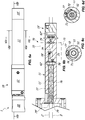
- the hinge 1 includes a fixed hinge body 20, a movable hinge body 10 and a connection assembly, indicated generally with 30, for mutual connection thereof.
- the movable hinge body 10 rotates with respect to the fixed one 20 around a longitudinal axis X, which may be substantially vertical, between an open door position, shown for example in FIGs. 3a to 4c , and a closed door position, shown for example in FIGs. 2a and 2b .
- the fixed hinge body 20 may be concealedly embedded within the wall that acts as a stationary support for the door.
- the movable hinge body 10 may be connected to the door.
- the fixed hinge body 20 may be anchored to the wall and the movable one 10 may be concealedly embedded within the door, without departing from the scope of the appended claims.
- the movable hinge body 10 may include a tubular member 11 defining an axis Y substantially perpendicular to the axis X and a first box-shaped element 12 susceptible to contain in its interior the connection assembly 30 when the movable hinge body 10 is in the door closed position, as shown for example in FIG. 2a .
- tubular element 11 may also belong to the hinge body 20, as well as that the hinge 1 can include more than one tubular element 11, without departing from the scope of the appended claims.
- tubular element 11 may have any shape, for example a cylindrical or parallelepiped shape with square or rectangular section, provided that it is internally hollow.
- connection assembly 30 is further configured to protude from the first box-shaped element 12 when the movable hinge body 20 is in the open door position, as shown for example in FIGs. 3a and 4a .
- the particular configuration of the connection assembly 30 is described later.
- the hinge 1 may have a different configuration, provided however that it includes a fixed element and a movable element coupled each other to rotate around an axis, without departing from the scope of the appended claims.
- the fixed and movable elements may be coupled in any manner, for example by a pivot.
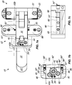
- the fixed hinge body 20 may include a second box-shaped element formed by a first outer element 21 and a second element 22 internal thereto, the latter cooperating with each other.
- the fixed hinge body 20 can be designed to be concealedly embedded within the door or the wall.
- the first outer element 21 may include first guide means for guiding the sliding of the second inner element 22 along a direction d which is substantially perpendicular to the axis X and the axis Y.
- the first outer element 21 may include a pair of first grooved surfaces 121 with a plurality of rows defining the direction d, while the second inner element 22 may include at least one corresponding pair of second countershaped surfaces 122 engaged with the first surfaces 121, which surfaces define the first guide means.
- the grooved surfaces 121, the countershaped surfaces 122 and a pair of screw elements 123', 123" designed for mutually engaging/disengaging thereof define means for reciprocally blocking/unblocking the first outer element 21 and the second inner element 22.
- each of the screw elements 123', 123" may include a respective screw 124', 124" to be engaged in a corresponding engagement element 125', 125" sliding in a respective elongate slot 126', 126", the latter being placed on surfaces 127', 127" opposite to the second countershaped surfaces 122.
- the first outer element 21 may include second guide means for guiding the sliding of the second inner element 22 along a direction d substantially parallel to the axis X and perpendicular to both the axis Y and to the direction d'.
- the second guide means may include two or more adjusting screws 128', 128" placed at opposite sides of the second inner element 22.
- the box-shaped element 12 can be formed by a first outer element 12' and a second element 12" internal thereto, the latter being mutually coupled each other.
- the box-shaped element 12 may define a hollow body with a pair of upper and lower walls 80, 81 substantially parallel to the axis Y joined by a side wall 82' and a bottom wall 82, the latter being substantially perpendicular to the side wall 82' and the axis Y.
- the upper and lower walls 80, 81 and the side wall 82' belong to the first outer element 12', while the bottom wall 82 may be a plate attached thereto.
- the side wall 82', the upper and lower walls 80 , 81 and the bottom wall 82 are susceptible to be concealed within the door or the wall, their inner side being however accessible from the outside. More precisely, if necessary, an operator can access from the outside, possibly with a tool (for example, a screwdriver), to the lower surface of the upper wall 80, the upper surface of the bottom wall 81, the front surface of the bottom wall 82 and to the inner surface of the side wall 82'.
- a tool for example, a screwdriver
- the box-shaped element may include two plate-shaped elements 87, 88 for attaching the movable hinge body 10 to the wall, preferably with screws or dowels to be inserted in the housings 89 ', 89 ".
- the front surface of the plate-shaped elements 87, 88 is susceptible to remain flush with the door and accessible once the hinge body 10 is concealed therein.
- the first box-shaped element 12 may comprise means for adjusting the sliding of the second inner element 12" with respect to the first outer element 12' along a plane substantially parallel to the axes X and Y, so as to adjust the distance and/or the inclination of the door with respect to the wall.
- the adjustment means may comprise a pair of actuator elements 212', 212" to be controlled by a user which are located at opposite end portions 213', 213" of the second inner element 12".
- Each of the actuator elements 212', 212" may be configured so that the rotation thereof imparted by the user corresponds to the sliding of the end portions 213', 213" along a direction d" substantially parallel to the axis Y.
- the two actuator elements 212', 212" may be equal to each other. Therefore, hereinafter it is described only one of them, it being understood that the other has the same configuration.
- the actuator element 212" may include a pin 214 having a first threaded portion 215' engaged in a corresponding counterthreaded seat 12'" of the first outer element 12' and a second portion 215" integrally coupled with a control element 216. More particularly, the latter and the pin 214 may be rotationally blocked relative to one another, for example by a plug or a suitable shaping with mutually engaged flat portions, and may be mutually coupled by means of a blocking element 217 adapted to mutually blocking relative to each other the second threaded portion 215", the end portion 213" of the second inner element 12" and the same control element 216.
- the end portion 213" of the second inner element 12" is interposed between the second threaded portion 215' and the control element 216.
- this is rotationally controlled from the outside by a user so that the rotation of the same control element 216 corresponds to the rotation of the pin 214.
- the user by doing so can adjust the relative position of the door with respect to the wall, in terms of distance and/or inclination.
- the mounting is extremely simplified. It is in fact sufficient to insert the pin 214 into the counterthreaded seat 12"', to insert the second inner element 12" into the first outer element 12' by placing the end portion 213" at the second threaded portion 215', to insert the control element 216 of the latter and block the assembly by means of the blocking element 217.
- the tubular element 11 may internally include a working chamber 13, which may in turn include means 40 for the automatic closing of the closing element once opened, and means 50 for the hydraulic damping of the pivotal movement of the movable hinge body 10.
- the means 40 for the automatic closing of the closing element after opening can be defined by elastic counteracting means, for example a coil spring.
- the means 50 for the hydraulic damping of the pivotal movement of the movable hinge body 10 may advantageously include a plunger member 51 sliding along the axis Y and a working fluid, such as oil, hydraulically acting thereon.
- hinge 1 may also be free of automatic closing means 40, thus being a hydraulic checking hinge or hydraulic brake.
- elastic counteracting means adapted to restore the initial position of the plunger member may be present or not.
- the plunger member 51 is mutually connected with the fixed hinge body 20 so that the rotation of the movable element 10 corresponds to the sliding of the former and vice-versa.
- At least one shaft 41 may be provided having a first end 42 operatively connected with the connection assembly 30 and a second end 43 mutually connected with the plunger member 51.
- the first end 42 of the at least one shaft 41 may be connected to the connecting assembly 30 via the connecting element 44, the latter being at one end screwed into the end 42 and at the other end connected to the first hook-shaped arm 31 by means of the first pin 32 '.
- the first end 42 of the former can pass through a central opening 83 of the bottom wall 82 of the box-shaped element 12.
- the second end 43 may be screwed onto the plunger member 51.
- the coil spring 40 can be fitted over the at least one shaft 41.
- the former can be fitted over the at least one shaft 41 so as to be in a position of maximum elongation when the movable hinge body 20 is in the door closed position, such as shown in FIGs. 2b and 10b .
- the working chamber 13 may be divided into two half-chambers 14, 15 separated each other by separation means 60.
- the separation means 60 may include a pair of seal 62', 62" so that the working fluid lies exclusively in the second half-chamber 15, the first half-chamber 14 remaining dry.
- the first half-chamber 14 may include means 40 for the automatic closing of the closing element once opened, while the second half-chamber 15 includes the hydraulic damping means 50. More particularly, the second half-chamber 15 includes the plunger member 51, the working fluid and at least one non-return valve which includes a respective at least one control member 52, for example of the butterfly type, and at least one end element 53.
- the at least one control member 52 may be movable within a respective at least one seat 54 which is defined when the plunger member 51 and the at least one end element 53 are engaged with each other.
- at least one of the front or rear surfaces of the plunger member 51 and the front surface of the at least one end element 53 are suitably configured so as to define the at least one seat 54 for the at least one control member 52.
- the first half-chamber 14 may be proximal to the axis X and/or to the first box-shaped element 12, while the second half-chamber 15 may be distal therefrom.
- the shaft 41 may be a single shaft placed in both the half-chambers 14 and 15. More particularly, the shaft 41 may have the first end 42 protruding from the first half-chamber 14 through the free end 16 for connection with the connecting element 44 and the second end 43 passing through the separation means 60 to lie within the second half-chamber 15.
- the coil spring 40 can be fit onto the single shaft 41 at the second end 46.
- the separation means 60 may include a radial appendix 61 extending radially towards the inner side of the working chamber 13 susceptible to abut against a radial appendix 45 of the shaft 41 which extends radially outwardly with respect to the second axis Y. More particularly, the radial appendix 45 of the shaft 41 may include a front surface 46 susceptible to come into contact with the spring 40 and a rear surface 47 susceptible to come into contact with the radial appendix 61 to act as end-stroke for the shaft 41.
- the second half-chamber 15 may be proximal to the axis X and/or to the first box-shaped element 12, while the first half-chamber 14 may be distal therefrom.
- a first shaft 41 placed exclusively within the second half-chamber 15 and a second shaft 41' placed within the first half-chamber 14 and the second half-chamber 15 may be provided.
- the second shaft 41' may have a third end 42' operatively connected with the plunger member 51 and a fourth end 43' lying in the first half-chamber 14.
- the coil spring 40 may be fitted onto the second shaft 41'.
- the latter may include means for adjusting the preload of the coil spring 40 including a slider 140 slidable along the second shaft 41' to act on the coil spring 40 and an actuator element 141 acting on the slider 140 to promote the sliding thereof in response to a rotation of the same actuator element 141 imparted by the user.
- the actuator element 141 can be accessed from the outside by the same user, for example by means of a tool with a shaped head inserted in a control countershaped portion 142 of the actuator element 141.
- this shaped head may for example be hexagonal.
- the slider 140 may be rotationally blocked, for example by one or more pins or by means of prismatic kinematic pairs, in particular two or more pairs of mutually engaged flat surfaces.
- pins or prismatic kinematic pairs also acts as guide means of the slider 140 along the second shaft 41'.
- the actuator element 141 may further be screwed on/unscrewed from the second shaft 41' and idly coupled with the slider 140 so that the screwing/unscrewing of the former imparted by the user for example by means of the above shaped head tool corresponds to the sliding of the slider 140.
- the plunger member 51 divides the second half-chamber 15 into two variable volume compartments 18, 19, fluidically communicating with each other and reciprocally adjacent.
- the first variable volume compartment 18 when the movable hinge body 10 is in the closed door position the first variable volume compartment 18 may have the maximum volume and the second variable volume compartment 19 may have the minimum volume.
- the first variable volume compartment 18 when the movable hinge body 20 is in the open door position the first variable volume compartment 18 may have the minimum volume and the second variable volume compartment 19 may have the maximum volume.
- a first line 55 for the fluidic connection of the compartments 18, 19 passing through the end element 53, the seat 54, the plunger member 51 and the second end 43 of the shaft 41 may be provided.
- a spring 252 acting on the at least one control member 52 for forcing the closing thereof against the at least one seat 54 may be provided, so as to minimize the closing time of the at least one valve and to have an optimal control on the closing element.
- the separation means 60 may be configured so that each of the half-chambers 14, 15 is accessible only through the respective free end 16, 17.
- the at least one end element 53, the at least one control member 52 and the plunger member 51 can be inserted within the second half-chamber 15 through the free end 17.
- the at least one control member 52 may be mount/dismount the at least one control member 52 in/from the at least one seat 54 which is formed by coupling the at least one end element 53 and the plunger member 51 outside the second half-chamber 15 and then insert the unitary assembly thus formed in the same second half-chamber 15, the at least one end element 53 and the plunger member 51 may be removably coupled.
- the plunger member 51 may include a threaded rear seat 56 adapted to receive the at least one end element 53, which may have a peripheral counterthreaded area 57.
- the plunger member 51 and the latter may also be removbly coupled.
- the second end 43 of the shaft 41 or the third single end 42' of the second shaft 41' may be threaded, while the plunger member 51 may include a corresponding counterthreaded seat 58.
- the end element 53 may include an elongated appendix 59 projecting from the free end 17. In this way, the operator is extremely facilitated in its task.
- the elongated appendix 59 may have a volume substantially equal to the volume of working fluid that passes between the first variable volume compartment 18 and the second variable volume compartment 19. In this way, it is possible to avoid imbalances and overpressure between the two compartments upon the passage of the fluid.
- the second half-chamber 15 may be closed by a cap 15' .
- the elongated appendix 59 may be configured to pass through the cap 15', and may have a control end 59' accessible by the operator to enable it mounting the unitary assembly of the end element 53, the control member 52 and the plunger member 51 on the shaft 41 with the cap 15' inserted within the second half-chamber 15.
- the cap 15' may have a central through hole 15 " acting both as a seat for the elongated appendix 59 and as a guide for the sliding thereof along the axis Y.
- the control end 59' may be accessible through the center hole 15".
- the unitary assembly may include a single end element 53 and a single control member 52 in addition to the plunger member 51.
- the unitary assembly in addition to the plunger member 51 includes a pair of non-return valves with a pair of control members 52, 52' movable in respective seats 54, 54' and a pair of end elements 53, 53'. Among the latter is interposed a third variable volume compartment 19', the function of which will be clear later.
- control members 52, 52' act in opposite directions, so that upon one of the opening or closing of the door one of the control members 52 opens and the other control member 52' closes, so that the working fluid flows selectively through only one of them durinf both the opening or the closing of the door.
- the unitary assembly of the end elements 53, 53', the control members 52, 52' and the plunger member 51 can be inserted within the second half-chamber 15 and controlled during coupling with the second shaft 41' by means of the first shaft 41, on which the unitary assembly is mounted in advance.
- the working fluid upon opening of the door the working fluid may pass from the first compartment 18 to the second compartment 19, while upon closing of the same door the working fluid may return from the second compartment 19 to the first compartment 18.
- the two variable volume compartments 18 and 19 are adjacent.
- the working fluid during the opening can pass through a fluid connection line 55 passing through the plunger member 51, while during the closing the working fluid may pass through another fluid line 70 different from the first one which passes through a channel made within the wall 11' of the tubular element 11.
- a third compartment 19' is interposed between the two variable volume compartments 18, 19.
- the working fluid passes through the plunger member 51 and the fluid line 70 passing through the wall 11' of the tubular element 11 both during opening and during closing of the door.
- the working fluid passes always through one of the control members 52, 52' and through the third compartment 19'.
- the fluid connection line 70 includes at least one channel passing through the wall 11 ' of the at least one portion 15 of the at least one working chamber 13.
- the fluid connection line 70 may include a pair of channels 71, 72 passing through the wall 11' of the tubular element 11 at the second half-chamber 15.
- FIG. 6b the two channels 71, 72 have been depicted with dotted lines.
- the channels 71, 72 may have a respective first and second opening 73, 74 in the first compartment 18 or fluidically communicating therewith, and a third and fourth opening 75, 75" in the second compartment 19. Both openings 75, 75" are placed along the same peripheral groove 175 of the second compartment 19.
- the channel 71 may be in fluid communication with the channel 72 through the peripheral groove 175.
- the first opening 73 can be fluidically decoupled from the plunger member 51 during all the stroke thereof.
- the second opening 74 may be fluidically coupled with the plunger member 51 for a first part of the stroke thereof and fluidically decoupled from the same plunger member 51 for a second part of the stroke thereof.
- the working fluid which is in the second compartment 19 passes through the third and fourth openings 75, 75" in the channels 71 and 72. From the latter, the working fluid arrives in the first compartment 18 through the two openings 73, 74.
- the two openings 73, 74 are placed at the third compartment 19', from which the working fluid reaches the first compartment 18 through the plunger member 51.
- the working fluid flows only through the first opening 73.
- the working fluid flows through both the first opening 73 and the second opening 74.
- the latter may be placed so as to remain fluidly decoupled from the plunger member 51 for a small part of the stroke thereof, corresponding to a residual rotation of the closing element of 10° - 20°.
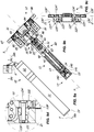
- a pair of adjusting elements 76, 77 may be provided passing through the bottom wall 82 of the box-shaped element 12 and the wall 11' of the tubular element 11.
- Each adjustment element 76, 77 may define a respective axis Z, Z' substantially parallel to the axis Y and perpendicular to the axis X, and may have a length sufficient to reach the respective channel 71, 72.
- each adjustment element 76, 77 may include a first operating end 78, 78' in correspondence of the respective channel 71, 72 to adjust the flow of the working fluid which flows through the same and a second control end 79, 79' at the bottom wall 82 of the box-shaped element 12 to allow a user to access thereon through the same box-shaped element 12.
- the adjustment element 76 which acts on the channel 71 adjusts the closing speed of the movable hinge body 10, while the adjustment element 77 regulates the latch of the movable hinge body 10 towards the door closed position.
- a third channel 72' may be further provided, shown particularly in FIGs. 12c and 12d , passing through the wall 11' of the tubular element 11 in correspondence of the second half-chamber 15.
- the third channel 72' may have a plurality of fifth openings 74' in the first compartment 18 and one other opening 75' fluidly communicating with the second compartment 19 through the third compartment 19'.
- the door control member 52 may be in the closed position, so that the working fluid is forced to pass through openings 74' within the channel 72'. Hence, the working fluid flows in the third compartment 19' through the opening 75'.
- the control member 52' can be open, so that the working fluid can pass through it in the second compartment 19.
- control member 52' can pass in the closed position, so that the working fluid which lies in the second compartment 19 is forced to pass through the openings 75, 75" within the channels 71, 72. Hence the working fluid reaches the third compartment 19' through the openings 73, 74, according to what has been described above.
- the control member 52 can be open, so that the working fluid can pass through it in the first compartment 18.
- a third adjustment element 77' may be provided having a respective control end 79" at the bottom wall 82 of the first box-shaped element 12 and an operating end 78 '" susceptible to selectively obstruct one or more of openings 74'.
- the adjustment is more or less fine.
- the adjustment is by steps, for example of 10° for each opening 74'.
- the third adjustment element 77' may be accessible from the outside by a user, for example through a screwdriver.
- the hinge 1 in any configuration may include only one of the channels 71, 72 or 72', as well as couples thereof ( 71 and 72, 71 and 72', 72 and 72' ) without departing from the scope of protection of the appended claims. It is further understood that the working fluid can pass through the channels and/or the plunger member in the other direction (for example, it may pass through the channels 71, 72 during opening and through the channel 72' during closing of the closing element) without departing from the scope of protection of the appended claims.
- connection assembly 30 is configured to lie within the first box-shaped element 12 when the movable hinge body 10 is in the closed door position and to extend therefrom when the same movable hinge body 10 is in the open door position.
- the top wall 80 and the bottom one 81 of the box-shaped element 12 may include a pair of sliders 83, 84 sliding in respective guides 85, 86 substantially parallel to the axis Y facing to each other.
- the first pin 32' in addition to mutually connect the first hook-shaped arm 31 with the shaft 41 via the connecting element 44, may pivotally connect the first arm 31 to the sliders 83, 84, at a first end 33' of the same first arm 31.
- the first hook-shaped arm 31 may be pivotally connected with the second box-shaped element 22 by means of a second pin 32".
- connection assembly 30 may further include a second substantially "L"-shaped arm 34 having a first end 35' pivotally connected to the box-shaped element 12 by means of a third pin 32 '", a second end 35" pivotally connected with a third arm 36 through a fourth pin 32"" and a third intermediate point 35 '" is rotatably connected with the first arm 31 by means of a fifth pin 32 '"".
- the first arm 31 may include a recess 31', while the second arm 34 may include a recess 34'.
- connection between the parts mentioned above may be effected in such a way that upon opening of the closing element the first end 33' of the first hook-shaped arm 31 may slide through the sliders 83, 84 along the guides 85, 86 along the axis Y and rotate it around the first plug 32' until the recess 31' impacts against the third pin 32 '".
- the second arm 34 can rotate about the third pin 32 '" until the recess 34' impacts against the second pin 32".
- the hinge 1 may have an opening angle greater or lesser.
- the embodiments of the hinge 1 shown in FIGs. 2a to 4c can open of 180°.
- connection assembly 30 may further include a third substantially plate-shaped arm 36 having a first end 37' pivotally connected to the box-shaped element 22 by means of a sixth pin 32""" and a second end 37" pivotally connected with the second end 35" of the second arm 34 by the fourth pin 32 "".
- the second arm 34 and third arm 36 may be connected to each other so that the rotation of the second arm 34 about the third pin 32 '" corresponds to the rotation of the third arm 36 about the fourth pin 32 "".
- the movable hinge body 10 can rotate about the first axis X.
- the hinge 1 may have the opening angle which is mechanically adjustable.
- the box-shaped element 12 may include a pair of adjusting screws 90, 91, which can have a respective control end 92', 92" that is accessible by an operator at the front surface 87', 88' of the plate-shaped elements 87, 88 and a respective operating end 93', 93" at the guides 85, 86 to act as end stroke for sliders 83, 84.
- the operator by acting on the control end 92', 92" moves axially, i.e. along a direction parallel to the axis Y, the screws 90, 91, by at the same moving the end stroke 93', 93" of the sliders 83, 84 and then the opening angle of the closing element.
- box-shaped element 12 may also include a single adjustment screw 90 without departing from the scope of the appended claims.
- the hinge 1 may have one or more stop door positions, such as the position of maximum opening, or the latter and an intermediate position.
- the box-shaped element 12 may include a pair of releasable engagement elements adapted to engage in corresponding seats 97', 97" formed on the sliders 83, 84.
- the releasable engagement means may be defined by a pair of balls 94, 95 inserted transversely through the openings 96', 96" passing through the side wall 82' of the box-shaped element 12.
- elastic pushing means may be provided acting on the same balls 94, 95, for example springs 98', 98".
- a user can act thereon to disengage the balls 94, 95 from the corresponding seats 97', 97". To do this, the user has to overcome the force imparted by the springs 98', 98".
- suitable adjustment screws 99', 99" may act on the springs 98', 98" inserted within the passing-through openings 96', 96".
- the operator can preset the blocking/unblocking force of the closing element, for example according to its weight or to the presence or absence of children in the house.
- box-shaped element 12 may include more pairs of balls 94, 95, so as to block the door in several positions, for example in the closed position, the open one and in one or more intermediate positions.
- the releasable engagement means may be defined by a pair of resilient arms 150', 150" unitary with the sliders 83, 84 suscetible to snap-engage in a groove 97', 97" unitary with the first box-shaped element 12.
- the latter may have a pair of abutment elements 151', 151" each comprising a respective groove 97', 97".
- each of the abutment elements 151', 151" may be slidably mounted in a respective seat 152', 152".
- each of the abutment elements 151', 151" may include one end 153', 153" accessible by a user to adjust the sliding thereof along the seats 152', 152", so as to adjust as needed the point where the resilient arms 150', 150" and grooves 97', 97" mutually engage.
- At least one of the at least one releasable engagement element 94, 95 and at least one seat 97', 97" may be removably fixed to the corresponding first box-shaped element 12, or to the corresponding slider 83, 84. In this way, a user may remove the same to provide a hinge free of stopping points of the closing element, for example for fire doors.
Description
- The present invention is generally applicable in the technical field of closing, opening and/or checking hinges, and particularly relates to a hydraulic hinge, in particular to a concealed hinge for doors.
- Hinges are known which comprise a fixed hinge body to be concealedly embedded in a wall, a movable hinge body to be anchored to a door and a connection assembly for mutual connection of the fixed hinge body and the movable one. In this way, the movable hinge body rotates with respect to the fixed one around a vertical axis between an open door position and a closed door position.
- The fixed hinge body includes a generally box-shaped element susceptible to internally contain the connection assembly of when the movable hinge body is in the closed door position. The connection assembly protrudes from the box-shaped element when the movable hinge body is in the open door position.
- The concelaed hinges of the type mentioned above available today on the market does not allow the control of the closing element during opening and/or closing.
- They are further bulky and include a large number of parts.
- Another drawback is the poor safety of such hinges, due to the fact that the doors to which are connected if pushed by a careless user is free to strongly impact against the frame to which they are anchored.
- From the documents
GB1252757 S4102006 GB2503753 US882721 ,DE102007031175 ,US2007/294860 andUS2709276 concealed hinges are known. - The object of the present invention is to overcome at least partly the above mentioned drawbacks, by providing a hinge having characteristics of high functionality and low cost.
- Another object of the invention is to provide a hinge that allows the control of the closing element during closing or opening.
- Another object of the invention is to provide a hinge of limited dimensions.
- Another object of the invention is to provide a hinge which ensures the automatic closing or opening of the closing element from the open and/or closed door position.
- Another object of the invention is to provide a hinge that is capable of supporting also very heavy doors, without changing the behavior.
- Another object of the invention is to provide a hinge which has a minimum number of constituent parts.
- Another object of the invention is to provide a hinge capable of maintaining the exact closing position over time.
- Another object of the invention is to provide a safe hinge.
- Another object of the invention is to provide a hinge easy to install.
- The above objects, as well as others that will appear more clearly hereinafter, are achieved by a hinge according to
claim 1. - Advantageous embodiments of the invention are defined according to the dependent claims.
- Further features and advantages of the invention will appear more evident upon reading the detailed description of a preferred, non-exclusive embodiment of a
hinge 1, which is described as non-limiting example with the help of the annexed drawings, wherein: -
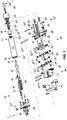
FIG. 1 is an exploded isometric view of an embodiment of thehinge 1, which embodiment does not fall within the scope of the appended claims; -
FIGs. 2a, 2b and2c are views respectively top, sectioned along a plane IIb - IIb and partially sectioned along a plane perpendicular to the plane IIb - IIb of the embodiment of thehinge 1 ofFIG. 1 in the closed position; -
FIGs. 3a, 3b and3c are views respectively top, sectioned along a plane IIIb - IIIb and partially sectioned along a plane perpendicular to the plane IIIb - IIIb of the embodiment of thehinge 1 ofFIG. 1 in a partially open position; -
FIGs. 4a, 4b and4c are views respectively top, sectioned along a plane IVb - IVb and partially sectioned along a plane perpendicular to the plane IVb - IVb of the embodiment of thehinge 1 ofFIG. 1 in the fully open position at 180°; -
FIGs. 5a, 5b and 5c are partially sectional views similar toFIGS. 2c, 3c and 4c of an alternative embodiment of thehinge 1 that does not fall within the scope of the appended claims, and that in the fully open position reaches 155°; -
FIGs. 6a, 6b, 6c and 6d are views respectively top, partially sectioned according to a plane VIb - Vib and sectioned along planes VIc - VIc and VId - VId of the embodiment of thehinge 1 ofFIG. 1 ; -
FIGs. 7a, 7b and 7c are views respectively axonometric in the open position and sectioned along a plane VIIb - VIIb and VIIc - VIIc of a further embodiment of thehinge 1 that does not fall within the scope of the appended claims; -
FIG. 8 is an exploded isometric view of an embodiment according to the invention of thehinge 1; -
FIGs. 9a, 9b and 9c are views respectively top in the open position and sectioned along a plane IXb - IXb and IXc - IXc of the embodiment of thehinge 1 ofFIG. 8 , with inFIG. 9d some enlarged details ofFIG. 9a ; -
FIGs. 10a and 10b are views respectively top in the closed position and sectioned along a plane Xb - Xb of the embodiment of thehinge 1 ofFIG. 8 , with inFIGs. 10c and10d some enlarged details ofFIG. 10b ; -
FIG. 11 is a front view of the embodiment of thehinge 1 ofFIG. 8 ; -
FIGs. 12a, 12b and 12c are views respectively sectioned along planes XIIa - XIIa, XIIb - XIIb and XIIc - XIIc inFIG. 11 of the embodiment of thehinge 1 ofFIG. 8 , with inFIG. 12d some enlarged details ofFIG. 12c ; -
FIG. 13 is a sectional view of some details of a further embodiment of thehinge 1. - With reference to the above figures, the
hinge 1 is advantageously to be used for the controlled rotatable movement of a door, during both opening and closing thereof. In general, the hinge according to the present invention may be used for closing and/or opening and/or controlling any closing element, such as a door, a window, a shutter or the like, anchored to any stationary support structure, such as a wall, a floor, a frame or the like, without departing from the scope of the appended claims. - In particular, the
hinge 1 may be of the concealed type and can be advantageously used with an internal door, for example a wooden door. Essentially, thehinge 1 includes afixed hinge body 20, amovable hinge body 10 and a connection assembly, indicated generally with 30, for mutual connection thereof. - As a result of this connection, the
movable hinge body 10 rotates with respect to the fixed one 20 around a longitudinal axis X, which may be substantially vertical, between an open door position, shown for example inFIGs. 3a to 4c , and a closed door position, shown for example inFIGs. 2a and 2b . - Suitably, the fixed
hinge body 20 may be concealedly embedded within the wall that acts as a stationary support for the door. On the other hand, themovable hinge body 10 may be connected to the door. - However, the opposite is possible, that is the fixed
hinge body 20 may be anchored to the wall and the movable one 10 may be concealedly embedded within the door, without departing from the scope of the appended claims. - Advantageously, the
movable hinge body 10 may include atubular member 11 defining an axis Y substantially perpendicular to the axis X and a first box-shapedelement 12 susceptible to contain in its interior theconnection assembly 30 when themovable hinge body 10 is in the door closed position, as shown for example inFIG. 2a . - It is understood that the
tubular element 11 may also belong to thehinge body 20, as well as that thehinge 1 can include more than onetubular element 11, without departing from the scope of the appended claims. - It is also understood that the
tubular element 11 may have any shape, for example a cylindrical or parallelepiped shape with square or rectangular section, provided that it is internally hollow. - The
connection assembly 30 is further configured to protude from the first box-shapedelement 12 when themovable hinge body 20 is in the open door position, as shown for example inFIGs. 3a and4a . The particular configuration of theconnection assembly 30 is described later. - It is understood that the
hinge 1 may have a different configuration, provided however that it includes a fixed element and a movable element coupled each other to rotate around an axis, without departing from the scope of the appended claims. The fixed and movable elements may be coupled in any manner, for example by a pivot. - The fixed
hinge body 20 may include a second box-shaped element formed by a firstouter element 21 and asecond element 22 internal thereto, the latter cooperating with each other. The fixedhinge body 20 can be designed to be concealedly embedded within the door or the wall. - In an embodiment according to the invention, shown in
FIGS. 8 to 12d , the firstouter element 21 may include first guide means for guiding the sliding of the secondinner element 22 along a direction d which is substantially perpendicular to the axis X and the axis Y. - To do this, the first
outer element 21 may include a pair of firstgrooved surfaces 121 with a plurality of rows defining the direction d, while the secondinner element 22 may include at least one corresponding pair of secondcountershaped surfaces 122 engaged with thefirst surfaces 121, which surfaces define the first guide means. - The
grooved surfaces 121, the countershaped surfaces 122 and a pair ofscrew elements 123', 123" designed for mutually engaging/disengaging thereof define means for reciprocally blocking/unblocking the firstouter element 21 and the secondinner element 22. - Advantageously, each of the
screw elements 123', 123" may include arespective screw 124', 124" to be engaged in acorresponding engagement element 125', 125" sliding in a respectiveelongate slot 126', 126", the latter being placed onsurfaces 127', 127" opposite to the second countershaped surfaces 122. - Suitably, the first
outer element 21 may include second guide means for guiding the sliding of the secondinner element 22 along a direction d substantially parallel to the axis X and perpendicular to both the axis Y and to the direction d'. The second guide means may include two or more adjusting screws 128', 128" placed at opposite sides of the secondinner element 22. - The box-shaped
element 12 can be formed by a first outer element 12' and asecond element 12" internal thereto, the latter being mutually coupled each other. As a whole, the box-shapedelement 12 may define a hollow body with a pair of upper andlower walls bottom wall 82, the latter being substantially perpendicular to the side wall 82' and the axis Y. - More particularly, the upper and
lower walls bottom wall 82 may be a plate attached thereto. - In use, the side wall 82', the upper and
lower walls bottom wall 82 are susceptible to be concealed within the door or the wall, their inner side being however accessible from the outside. More precisely, if necessary, an operator can access from the outside, possibly with a tool (for example, a screwdriver), to the lower surface of theupper wall 80, the upper surface of thebottom wall 81, the front surface of thebottom wall 82 and to the inner surface of the side wall 82'. - Moreover, the box-shaped element may include two plate-shaped
elements movable hinge body 10 to the wall, preferably with screws or dowels to be inserted in thehousings 89', 89". - The front surface of the plate-shaped
elements hinge body 10 is concealed therein. - In a preferred but not exclusive embodiment, shown in
FIGs. 8 to 12d , the first box-shapedelement 12 may comprise means for adjusting the sliding of the secondinner element 12" with respect to the first outer element 12' along a plane substantially parallel to the axes X and Y, so as to adjust the distance and/or the inclination of the door with respect to the wall. - Suitably, the adjustment means may comprise a pair of
actuator elements 212', 212" to be controlled by a user which are located atopposite end portions 213', 213" of the secondinner element 12". - Each of the
actuator elements 212', 212" may be configured so that the rotation thereof imparted by the user corresponds to the sliding of theend portions 213', 213" along a direction d" substantially parallel to the axis Y. - The two
actuator elements 212', 212" may be equal to each other. Therefore, hereinafter it is described only one of them, it being understood that the other has the same configuration. - The
actuator element 212" may include apin 214 having a first threaded portion 215' engaged in a corresponding counterthreaded seat 12'" of the first outer element 12' and asecond portion 215" integrally coupled with acontrol element 216. More particularly, the latter and thepin 214 may be rotationally blocked relative to one another, for example by a plug or a suitable shaping with mutually engaged flat portions, and may be mutually coupled by means of a blockingelement 217 adapted to mutually blocking relative to each other the second threadedportion 215", theend portion 213" of the secondinner element 12" and thesame control element 216. - Therefore, the
end portion 213" of the secondinner element 12" is interposed between the second threaded portion 215' and thecontrol element 216. - Moreover, this is rotationally controlled from the outside by a user so that the rotation of the
same control element 216 corresponds to the rotation of thepin 214. As a consequence, the user by doing so can adjust the relative position of the door with respect to the wall, in terms of distance and/or inclination. - Moreover, thanks to the above configuration, the mounting is extremely simplified. It is in fact sufficient to insert the
pin 214 into thecounterthreaded seat 12"', to insert the secondinner element 12" into the first outer element 12' by placing theend portion 213" at the second threaded portion 215', to insert thecontrol element 216 of the latter and block the assembly by means of the blockingelement 217. - The
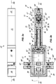
tubular element 11 may internally include a workingchamber 13, which may in turn include means 40 for the automatic closing of the closing element once opened, and means 50 for the hydraulic damping of the pivotal movement of themovable hinge body 10. - Suitably, the
means 40 for the automatic closing of the closing element after opening can be defined by elastic counteracting means, for example a coil spring. - Moreover, the
means 50 for the hydraulic damping of the pivotal movement of themovable hinge body 10 may advantageously include aplunger member 51 sliding along the axis Y and a working fluid, such as oil, hydraulically acting thereon. - It is understood that the
hinge 1 may also be free of automatic closing means 40, thus being a hydraulic checking hinge or hydraulic brake. In this case, elastic counteracting means adapted to restore the initial position of the plunger member may be present or not. - The
plunger member 51 is mutually connected with the fixedhinge body 20 so that the rotation of themovable element 10 corresponds to the sliding of the former and vice-versa. - For this purpose, at least one
shaft 41 may be provided having afirst end 42 operatively connected with theconnection assembly 30 and asecond end 43 mutually connected with theplunger member 51. - The
first end 42 of the at least oneshaft 41 may be connected to the connectingassembly 30 via the connectingelement 44, the latter being at one end screwed into theend 42 and at the other end connected to the first hook-shapedarm 31 by means of the first pin 32'. - To allow the connection between the at least one
shaft 41 and the connectingelement 44, thefirst end 42 of the former can pass through acentral opening 83 of thebottom wall 82 of the box-shapedelement 12. - As better explained below, the
second end 43 may be screwed onto theplunger member 51. - The
coil spring 40 can be fitted over the at least oneshaft 41. In particular, the former can be fitted over the at least oneshaft 41 so as to be in a position of maximum elongation when themovable hinge body 20 is in the door closed position, such as shown inFIGs. 2b and10b . - In order to functionally split the
means 40 for the automatic closing of the closing element once opened and themeans 50 for the hydraulic damping of the pivotal movement of themovable hinge body 10, the workingchamber 13 may be divided into two half-chambers - Advantageously, the separation means 60 may include a pair of
seal 62', 62" so that the working fluid lies exclusively in the second half-chamber 15, the first half-chamber 14 remaining dry. - In this way, it is possible to use a
spring 40 greatly longer (and hence having more force) than the one which could have been inserted in the limited space of the half-chamber 15. - Suitably, the first half-
chamber 14 may include means 40 for the automatic closing of the closing element once opened, while the second half-chamber 15 includes the hydraulic dampingmeans 50. More particularly, the second half-chamber 15 includes theplunger member 51, the working fluid and at least one non-return valve which includes a respective at least onecontrol member 52, for example of the butterfly type, and at least oneend element 53. - The at least one
control member 52 may be movable within a respective at least oneseat 54 which is defined when theplunger member 51 and the at least oneend element 53 are engaged with each other. In other words, at least one of the front or rear surfaces of theplunger member 51 and the front surface of the at least oneend element 53 are suitably configured so as to define the at least oneseat 54 for the at least onecontrol member 52. - Such details are described in detail later. In an embodiment not falling within the appended claims, shown in FIGa. 1 to 7c, the first half-
chamber 14 may be proximal to the axis X and/or to the first box-shapedelement 12, while the second half-chamber 15 may be distal therefrom. - In this case, the
shaft 41 may be a single shaft placed in both the half-chambers shaft 41 may have thefirst end 42 protruding from the first half-chamber 14 through thefree end 16 for connection with the connectingelement 44 and thesecond end 43 passing through the separation means 60 to lie within the second half-chamber 15. - The
coil spring 40 can be fit onto thesingle shaft 41 at thesecond end 46. - The separation means 60 may include a
radial appendix 61 extending radially towards the inner side of the workingchamber 13 susceptible to abut against aradial appendix 45 of theshaft 41 which extends radially outwardly with respect to the second axis Y. More particularly, theradial appendix 45 of theshaft 41 may include afront surface 46 susceptible to come into contact with thespring 40 and arear surface 47 susceptible to come into contact with theradial appendix 61 to act as end-stroke for theshaft 41. - In the embodiment according to the invention, shown in
FIGs. 8 to 12d , the second half-chamber 15 may be proximal to the axis X and/or to the first box-shapedelement 12, while the first half-chamber 14 may be distal therefrom. - In this case, a
first shaft 41 placed exclusively within the second half-chamber 15 and a second shaft 41' placed within the first half-chamber 14 and the second half-chamber 15 may be provided. - The second shaft 41' may have a third end 42' operatively connected with the
plunger member 51 and a fourth end 43' lying in the first half-chamber 14. Thecoil spring 40 may be fitted onto the second shaft 41'. - Conveniently, the latter may include means for adjusting the preload of the
coil spring 40 including aslider 140 slidable along the second shaft 41' to act on thecoil spring 40 and anactuator element 141 acting on theslider 140 to promote the sliding thereof in response to a rotation of thesame actuator element 141 imparted by the user. - To do this, the
actuator element 141 can be accessed from the outside by the same user, for example by means of a tool with a shaped head inserted in acontrol countershaped portion 142 of theactuator element 141. In a preferred but not exclusive embodiment, this shaped head may for example be hexagonal. - In order to preload the
coil spring 40, theslider 140 may be rotationally blocked, for example by one or more pins or by means of prismatic kinematic pairs, in particular two or more pairs of mutually engaged flat surfaces. - Suitably, pins or prismatic kinematic pairs also acts as guide means of the
slider 140 along the second shaft 41'. - The
actuator element 141 may further be screwed on/unscrewed from the second shaft 41' and idly coupled with theslider 140 so that the screwing/unscrewing of the former imparted by the user for example by means of the above shaped head tool corresponds to the sliding of theslider 140. - The
plunger member 51 divides the second half-chamber 15 into two variable volume compartments 18, 19, fluidically communicating with each other and reciprocally adjacent. - Suitably, when the
movable hinge body 10 is in the closed door position the firstvariable volume compartment 18 may have the maximum volume and the secondvariable volume compartment 19 may have the minimum volume. On the other hand, when themovable hinge body 20 is in the open door position the firstvariable volume compartment 18 may have the minimum volume and the secondvariable volume compartment 19 may have the maximum volume. - Therefore, upon the opening of the closing element the working fluid passes from the first
variable volume compartment 18 to the secondvariable volume compartment 19. To this end, in a first embodiment shown inFIGs. 1 to 7c , afirst line 55 for the fluidic connection of thecompartments end element 53, theseat 54, theplunger member 51 and thesecond end 43 of theshaft 41 may be provided. - In a preferred but not exclusive embodiment, shown in
FIG. 13 , aspring 252 acting on the at least onecontrol member 52 for forcing the closing thereof against the at least oneseat 54 may be provided, so as to minimize the closing time of the at least one valve and to have an optimal control on the closing element. - The separation means 60 may be configured so that each of the half-
chambers free end - Therefore, the at least one
end element 53, the at least onecontrol member 52 and theplunger member 51 can be inserted within the second half-chamber 15 through thefree end 17. - To allow an operator to mount/dismount the at least one
control member 52 in/from the at least oneseat 54 which is formed by coupling the at least oneend element 53 and theplunger member 51 outside the second half-chamber 15 and then insert the unitary assembly thus formed in the same second half-chamber 15, the at least oneend element 53 and theplunger member 51 may be removably coupled. To do this, theplunger member 51 may include a threadedrear seat 56 adapted to receive the at least oneend element 53, which may have a peripheralcounterthreaded area 57. - To allow the operator to mount the unitary assembly of the at least one
end element 53, the at least onecontrol member 52 and theplunger member 51 which has been previously formed onto thesingle shaft 41 in the case of the embodiment shown inFIGs. 1 to 7c and the second shaft 41' in the case of the embodiment shown inFIGS. 8 to 12d , theplunger member 51 and the latter may also be removbly coupled. - To this end, the
second end 43 of theshaft 41 or the third single end 42' of the second shaft 41' may be threaded, while theplunger member 51 may include a correspondingcounterthreaded seat 58. - In this way, it is possible to mount in a simple and fast manner the unitary assembly of the at least one
end element 53, the at least onecontrol member 52 and theplunger member 51 on thesingle shaft 41 or on the second shaft 41' without the aid of screws or similar fastening elements. - To allow the operator to control the unitary assembly between of the at least one
end element 53, the at least onecontrol member 52 and theplunger member 51 once inserted within the second half-chamber 15, in the embodiment shown inFIGs. 1 to 7c theend element 53 may include anelongated appendix 59 projecting from thefree end 17. In this way, the operator is extremely facilitated in its task. - Suitably, the
elongated appendix 59 may have a volume substantially equal to the volume of working fluid that passes between the firstvariable volume compartment 18 and the secondvariable volume compartment 19. In this way, it is possible to avoid imbalances and overpressure between the two compartments upon the passage of the fluid. - In a preferred but not exclusive embodiment, the second half-
chamber 15 may be closed by a cap 15'. - In this case, the
elongated appendix 59 may be configured to pass through the cap 15', and may have a control end 59' accessible by the operator to enable it mounting the unitary assembly of theend element 53, thecontrol member 52 and theplunger member 51 on theshaft 41 with the cap 15' inserted within the second half-chamber 15. - To do this, the cap 15' may have a central through
hole 15" acting both as a seat for theelongated appendix 59 and as a guide for the sliding thereof along the axis Y. The control end 59' may be accessible through thecenter hole 15". - In this embodiment, the unitary assembly may include a
single end element 53 and asingle control member 52 in addition to theplunger member 51. - On the other hand, in the embodiment according to the invention shown in
FIGs. 8 to 12d , the unitary assembly in addition to theplunger member 51 includes a pair of non-return valves with a pair ofcontrol members 52, 52' movable inrespective seats 54, 54' and a pair ofend elements 53, 53'. Among the latter is interposed a third variable volume compartment 19', the function of which will be clear later. - In this embodiment, the
control members 52, 52' act in opposite directions, so that upon one of the opening or closing of the door one of thecontrol members 52 opens and the other control member 52' closes, so that the working fluid flows selectively through only one of them durinf both the opening or the closing of the door. - Moreover, in this embodiment the unitary assembly of the
end elements 53, 53', thecontrol members 52, 52' and theplunger member 51 can be inserted within the second half-chamber 15 and controlled during coupling with the second shaft 41' by means of thefirst shaft 41, on which the unitary assembly is mounted in advance. - As mentioned above, upon opening of the door the working fluid may pass from the
first compartment 18 to thesecond compartment 19, while upon closing of the same door the working fluid may return from thesecond compartment 19 to thefirst compartment 18. - In the first embodiment shown in
FIGs. 1 to 7c , the two variable volume compartments 18 and 19 are adjacent. In this case, the working fluid during the opening can pass through afluid connection line 55 passing through theplunger member 51, while during the closing the working fluid may pass through anotherfluid line 70 different from the first one which passes through a channel made within the wall 11' of thetubular element 11. - As mentioned above, in the embodiment according to the invention shown in
FIGs. 8 to 12d a third compartment 19' is interposed between the two variable volume compartments 18, 19. In this case, the working fluid passes through theplunger member 51 and thefluid line 70 passing through the wall 11' of thetubular element 11 both during opening and during closing of the door. In particular, the working fluid passes always through one of thecontrol members 52, 52' and through the third compartment 19'. - According to the invention, the
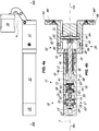
fluid connection line 70 includes at least one channel passing through the wall 11' of the at least oneportion 15 of the at least one workingchamber 13. Alternatively, thefluid connection line 70 may include a pair ofchannels tubular element 11 at the second half-chamber 15. - To allow an easy understanding, in
FIG. 6b the twochannels - To allow the connection between the two
compartments channels second opening first compartment 18 or fluidically communicating therewith, and a third andfourth opening second compartment 19. Bothopenings peripheral groove 175 of thesecond compartment 19. - The
channel 71 may be in fluid communication with thechannel 72 through theperipheral groove 175. - Suitably, the
first opening 73 can be fluidically decoupled from theplunger member 51 during all the stroke thereof. - On the other hand, the
second opening 74 may be fluidically coupled with theplunger member 51 for a first part of the stroke thereof and fluidically decoupled from thesame plunger member 51 for a second part of the stroke thereof. - Therefore, upon closing of the closing element as the
plunger member 51 moves the working fluid which is in thesecond compartment 19 passes through the third andfourth openings channels first compartment 18 through the twoopenings FIGs. 8 to 12d , the twoopenings first compartment 18 through theplunger member 51. - For the first part of the stroke of the
plunger member 51, that is until the latter and thesecond opening 74 are fluidically coupled, the working fluid flows only through thefirst opening 73. For the second part of the stroke of theplunger member 51, that is when the latter and thesecond opening 74 are fluidically decoupled, the working fluid flows through both thefirst opening 73 and thesecond opening 74. Advantageously, the latter may be placed so as to remain fluidly decoupled from theplunger member 51 for a small part of the stroke thereof, corresponding to a residual rotation of the closing element of 10° - 20°. - The sudden flowing of a greater amount of working fluid in the
first compartment 18 causes the snap-on forwarding of theplunger member 51, with consequent latch of the closing element towards the closed position. - To allow to adjust both the speed and the latch of the closing element, a pair of adjusting
elements bottom wall 82 of the box-shapedelement 12 and the wall 11' of thetubular element 11. - Each
adjustment element respective channel - More particularly, each
adjustment element first operating end 78, 78' in correspondence of therespective channel second control end 79, 79' at thebottom wall 82 of the box-shapedelement 12 to allow a user to access thereon through the same box-shapedelement 12. - In this way, it is possible to regulate the flow of the working fluid which flows through the
channels hinge 1 is mounted and themovable hinge body 10 is concealed within the door. - The
adjustment element 76 which acts on thechannel 71 adjusts the closing speed of themovable hinge body 10, while theadjustment element 77 regulates the latch of themovable hinge body 10 towards the door closed position. - In the embodiment shown in
FIGs. 8 to 12d , a third channel 72' may be further provided, shown particularly inFIGs. 12c and12d , passing through the wall 11' of thetubular element 11 in correspondence of the second half-chamber 15. - The third channel 72' may have a plurality of fifth openings 74' in the
first compartment 18 and one other opening 75' fluidly communicating with thesecond compartment 19 through the third compartment 19'. - In this way, during the opening of the
door control member 52 may be in the closed position, so that the working fluid is forced to pass through openings 74' within the channel 72'. Hence, the working fluid flows in the third compartment 19' through the opening 75'. The control member 52' can be open, so that the working fluid can pass through it in thesecond compartment 19. - During the closing of the door the control member 52' can pass in the closed position, so that the working fluid which lies in the
second compartment 19 is forced to pass through theopenings channels openings control member 52 can be open, so that the working fluid can pass through it in thefirst compartment 18. - Advantageously, a third adjustment element 77' may be provided having a respective control end 79" at the
bottom wall 82 of the first box-shapedelement 12 and an operating end 78'" susceptible to selectively obstruct one or more of openings 74'. - In this way, it is possible to hydraulically limit the opening angle of the door. Depending on the number of openings 74' obstructed/free by the operating end 78'" of the third adjustment element 77', it is possible to vary the opening angle of the door.
- Depending on the configuration and/or the mutual distance between the openings 74', the adjustment is more or less fine. For example, the adjustment is by steps, for example of 10° for each opening 74'.
- Similarly to the other two adjustment elements, the third adjustment element 77' may be accessible from the outside by a user, for example through a screwdriver.
- It is understood that the
hinge 1 in any configuration may include only one of thechannels channels - As mentioned above, the
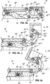
connection assembly 30 is configured to lie within the first box-shapedelement 12 when themovable hinge body 10 is in the closed door position and to extend therefrom when the samemovable hinge body 10 is in the open door position. - To this end, the
top wall 80 and thebottom one 81 of the box-shapedelement 12 may include a pair ofsliders respective guides arm 31 with theshaft 41 via the connectingelement 44, may pivotally connect thefirst arm 31 to thesliders first arm 31. At theother end 33" the first hook-shapedarm 31 may be pivotally connected with the second box-shapedelement 22 by means of asecond pin 32". - The
connection assembly 30 may further include a second substantially "L"-shapedarm 34 having a first end 35' pivotally connected to the box-shapedelement 12 by means of a third pin 32'", asecond end 35" pivotally connected with athird arm 36 through afourth pin 32"" and a third intermediate point 35'" is rotatably connected with thefirst arm 31 by means of a fifth pin 32'"". - Advantageously, the
first arm 31 may include a recess 31', while thesecond arm 34 may include a recess 34'. - The connection between the parts mentioned above may be effected in such a way that upon opening of the closing element the first end 33' of the first hook-shaped
arm 31 may slide through thesliders guides second arm 34 can rotate about the third pin 32'" until the recess 34' impacts against thesecond pin 32". - Depending on the configuration of the recess 34', the
hinge 1 may have an opening angle greater or lesser. For example, the embodiments of thehinge 1 shown inFIGs. 2a to 4c can open of 180°. - Advantageously, the
connection assembly 30 may further include a third substantially plate-shapedarm 36 having a first end 37' pivotally connected to the box-shapedelement 22 by means of asixth pin 32""" and asecond end 37" pivotally connected with thesecond end 35" of thesecond arm 34 by thefourth pin 32"". - The
second arm 34 andthird arm 36 may be connected to each other so that the rotation of thesecond arm 34 about the third pin 32'" corresponds to the rotation of thethird arm 36 about thefourth pin 32"". - In this way, the
movable hinge body 10 can rotate about the first axis X. - In a preferred but not exclusive embodiment, the
hinge 1 may have the opening angle which is mechanically adjustable. - To do this, the box-shaped
element 12 may include a pair of adjustingscrews elements respective operating end 93', 93" at theguides sliders - Therefore, the operator by acting on the
control end 92', 92" moves axially, i.e. along a direction parallel to the axis Y, thescrews end stroke 93', 93" of thesliders - Since, as particularly shown in
FIG. 7a , the front surface 87', 88' of the plate-shapedelements - It is understood that the box-shaped
element 12 may also include asingle adjustment screw 90 without departing from the scope of the appended claims. - In a further preferred but not exclusive embodiment, the
hinge 1 may have one or more stop door positions, such as the position of maximum opening, or the latter and an intermediate position. - To do this, in the first embodiment shown in
FIGs. 1 to 7c the box-shapedelement 12 may include a pair of releasable engagement elements adapted to engage in correspondingseats 97', 97" formed on thesliders - More particularly, in the first embodiment shown in
FIGs. 1 to 7c the releasable engagement means may be defined by a pair ofballs openings 96', 96" passing through the side wall 82' of the box-shapedelement 12. - To push the
balls seats 97', 97" and at the same time to allow the disengagement of the former from the latter, elastic pushing means may be provided acting on thesame balls - Therefore, once the
sliders guides balls springs 98', 98" pushes the latter to engage within therespective seats 97', 97", thus stopping the sliding of thesliders - To unblock the door, a user can act thereon to disengage the
balls seats 97', 97". To do this, the user has to overcome the force imparted by thesprings 98', 98". - To allow presetting of such force, suitable adjustment screws 99', 99" may act on the
springs 98', 98" inserted within the passing-throughopenings 96', 96". - In this way, by turning the adjusting screws 99', 99" the operator can preset the blocking/unblocking force of the closing element, for example according to its weight or to the presence or absence of children in the house.
- It is understood that the box-shaped
element 12 may include more pairs ofballs - It is further understood that it is also possible to use only one of the
balls - On the other hand, in the second embodiment shown in
FIGs. 8 to 12d the releasable engagement means may be defined by a pair ofresilient arms 150', 150" unitary with thesliders groove 97', 97" unitary with the first box-shapedelement 12. - More specifically, as particularly shown in
FIG. 10b , the latter may have a pair ofabutment elements 151', 151" each comprising arespective groove 97', 97". - To allow a user to mechanically adjust the opening angle of the closing element, each of the
abutment elements 151', 151" may be slidably mounted in arespective seat 152', 152". In addition, each of theabutment elements 151', 151" may include oneend 153', 153" accessible by a user to adjust the sliding thereof along theseats 152', 152", so as to adjust as needed the point where theresilient arms 150', 150" andgrooves 97', 97" mutually engage. - Suitably, regardless of the configuration, at least one of the at least one
releasable engagement element seat 97', 97" may be removably fixed to the corresponding first box-shapedelement 12, or to the correspondingslider - From the above, it is apparent that the hinge according to the invention achieves the intended objects.
- The hinge according to the invention is susceptible of numerous modifications and variations, all within the inventive concept expressed in the accompanying claims. All the details may be replaced with other technically equivalent elements, and the materials may be different according to requirements, without departing from the scope of the invention.
- Even if the hinge has been described with particular reference to the accompanying figures, reference numbers used in the description and in the claims are merely used to improve the intelligence of the invention and do not constitute any limitation of the claimed scope.
Claims (11)
- A hydraulic hinge for closing and/or opening and/or checking a closing element, such as a door, a window, a door or the like, fixed to a stationary support structure, such as a wall, a floor, a frame or the like, the hinge comprising:- a fixed element (20) anchorable to the stationary support structure;- a movable element (10) anchorable to the closing element, said fixed element (20) and movable element (10) being mutually coupled in such a manner that the latter (10) rotates with respect to the former (20) about a first longitudinal axis (X) between an open position and a closed position;wherein one of said fixed element (20) and movable element (10) includes at least one working chamber (13) defining a second longitudinal axis (Y), said at least one working chamber (13) comprising at least one portion (15) which includes:- a plunger member (51) slidable along said second axis (Y), said plunger member (51) being mutually connected with the other of said fixed element (20) and movable element (10) so that the rotation of the latter (10) corresponds to the sliding of the former (51) and vice-versa;- a working fluid for hydraulically damping the movement of said movable element (10);wherein said plunger member (51) divides said at least one portion (15) of said at least one working chamber (13) in at least two variable volume compartments (18, 19) fluidically communicating with each other;
wherein upon one of the opening or closing of the closing element the working fluid flows from one of said first compartment (18) and second compartment (19) to the other of said first compartment (18) and second compartment (19), upon the other of the opening or closing of the closing element the working fluid flowing from the other of said first compartment (18) and second compartment (19) to said one of said first compartment (18) and second compartment (19);
characterized in that the hinge further comprises a third compartment (19') interposed between said first compartment (18) and said second compartment (19), said at least one portion (15) of said at least one working chamber (13) comprising a pair of non-return valves with a pair of control members (52, 52') sliding in respective seats (54, 54'), including respective end members (53, 53') cooperating therewith to define said seats (54, 54'), said third compartment (19') being interposed between said end members (53, 53');
wherein said control members (52, 52') act in opposite directions in such a manner that upon one of the opening or closing of the closing element one of said control members (52, 52') opens and the other of said control members (52, 52') closes, and in such a manner that upon the other of the opening or closing of the closing element said one of said control members (52, 52') closes and said other of said control members (52, 52') opens, so that the working fluid selectively flows through only one therof (52, 52') during both opening and closing of the closing element;
wherein upon one of the opening or closing of the closing element the working fluid flows between said first compartment (18) and second compartment (19) through said third compartment (19') and through_at least one channel (71, 72) passing through the wall (11') of said at least one portion (15) of said at least one working chamber (13), - Hinge according to claim 1, further comprising elastic counteracting means (40) to allow opening/closing of the closing element once closed/open.
- Hinge according to claim 2, wherein said elastic counteracting means (40) move between a position of maximum and minimum elongation, said elastic counteracting means (40) being in the position of maximum elongation when said movable element (10) is in the closed position.
- Hinge according to claim 1, 2 or 3, wherein when said movable element (10) is in said closed position said first variable volume compartment (18) has the maximum volume and said second variable volume compartment (19) has the minimum volume.
- Hinge according to one or more of the preceding claims, wherein the hinge is of the concealed type, the fixed element (20) including a fixed hinge body (20), the movable element (10) including a movable hinge body (10), the hinge further comprising a connecting assembly (30) for mutual connection of said fixed hinge body (20) and movable hinge body (10) so that the latter (10) rotates with respect to the former (20) around said first longitudinal axis (X), said one of said fixed hinge body (20) or said movable hinge body (10) including at least one tubular element (11) concealedly insertable within one of the closing element and the stationary support structure and a first box-shaped element (12) susceptible to internally contain said connecting assembly (30) in the closed position of the movable element (10), said at least one tubular element (11) defining said second axis (Y), the latter being substantially perpendicular to said first axis (X), said connecting assembly (30) protruding from said first box-shaped element (12) in the open position of the movable element (10), said at least one tubular element (11) internally including said at least one working chamber (13).
- Hinge according to one or more of claims 1 to 5, wherein said at least one channel (71) includes a first channel (71) and/or a second channel (72), said first channel (71) having a first opening (73) fluidically communicating with said first compartment (18) and a third opening (75) fluidically communicating with said second compartment (19), said second channel (72) further passing through the wall (11') of said working chamber (13), said at least one second channel (72) including a second opening (74) fluidically communicating with said first compartment (18) and a fourth opening (75") fluidically communicating with said second compartment (19), a pair of said adjustment elements (76, 77) being provided each having a respective operative end (78, 78') at the respective at least one first or second channel (71, 72) and a respective control end (79, 79') accessible from outside by a user.
- Hinge according to the preceding claim, wherein said second opening (73) is fluidically decoupled from said plunger member (51) for the entire stroke thereof, the respective adjustment element (76) adjusting the opening/closing speed of said movable hinge body (10).
- Hinge according to the preceding claim, wherein said second opening (74) is fluidically coupled with said plunger member (51) for a first part of the stroke thereof and fluidically decoupled from said plunger member (51) for a second part thereof, the respective adjustment element (77) adjusting the latch action of the movable hinge body (10) towards the open/closed position.
- Hinge according to one or more of claims 1 to 8, wherein said at least one channel (71, 72) has a third channel (72') passing through the wall (11') of said working chamber (13), said third channel (72') including a plurality of fifth openings (74') fluidically communicating with said first compartment (18) and a sixth opening (75') fluidically communicating with said second compartment (19), a third adjusting element (77') being provided having a respective control end (79") accessible from outside by a user and an operative end (78'") which selectively obstruct one or more of said fifth openings (74') of said plurality to hydraulically limit the opening or closing angle of the closing element.
- Hinge according to one or more of claims 1 to 9, wherein the working fluid flows between said first compartment (18) and said second compartment (19) through said third compartment (19'), said hinge including said third channel (72') and at least one of said first channel and/or second channel (71, 72), the working fluid flowing from said first compartment (18) to said second compartment (19) passing through one of said third channel (72') and at least one of said first channel and/or second channel (71, 72), the working fluid flowing from said second compartment (19) to said first compartment (18) passing through the other of said third channel (72') and at least one of said first channel and/or second channel (71, 72).
- Hinge according to any one of claims 1 to 10, wherein said end members (53) and said plunger member (51) are removably coupled so as to allow an operator to mount/unmount said control members (52) from/into said seats (54) externally to the at least one portion (15) of said at least one working chamber (13) and insert the assembly unit (51, 52, 53) thus formed therein.
Applications Claiming Priority (4)
| Application Number | Priority Date | Filing Date | Title |
|---|---|---|---|
| ITVI20140070 | 2014-03-25 | ||
| ITVI20140072 | 2014-03-25 | ||
| ITVI20140073 | 2014-03-25 | ||
| PCT/IB2015/052183 WO2015145364A2 (en) | 2014-03-25 | 2015-03-25 | Hydraulic hinge, in particular concealed hinge for doors |
Publications (2)
| Publication Number | Publication Date |
|---|---|
| EP3122972A2 EP3122972A2 (en) | 2017-02-01 |
| EP3122972B1 true EP3122972B1 (en) | 2020-12-09 |
Family
ID=53051850
Family Applications (1)
| Application Number | Title | Priority Date | Filing Date |
|---|---|---|---|
| EP15720432.2A Active EP3122972B1 (en) | 2014-03-25 | 2015-03-25 | Hydraulic hinge, in particular concealed hinge for doors |
Country Status (8)
| Country | Link |
|---|---|
| US (2) | US9803410B2 (en) |
| EP (1) | EP3122972B1 (en) |
| JP (1) | JP6677647B2 (en) |
| KR (1) | KR102302033B1 (en) |
| CN (1) | CN106232922B (en) |
| CA (2) | CA2942161C (en) |
| RU (1) | RU2675323C2 (en) |
| WO (1) | WO2015145364A2 (en) |
Families Citing this family (13)
| Publication number | Priority date | Publication date | Assignee | Title |
|---|---|---|---|---|
| ITVI20130195A1 (en) * | 2013-07-30 | 2015-01-31 | Ol Mi S R L | HINGE FOR THE TURNTABLE HANDLING OF A DOOR, A CORE OR SIMILAR |
| EP3274533B1 (en) * | 2015-03-25 | 2020-01-15 | OL.MI Srl | Concealed hinge for doors |
| ITUA20164276A1 (en) * | 2016-06-10 | 2017-12-10 | Anselmi & C S R L | PERFECT AUTOMATIC DOOR CLOSER DEVICE |
| RU2738640C2 (en) * | 2016-06-10 | 2020-12-15 | Анселми И К. С.Р.Л. | Automatic door closing device |
| IT201600116925A1 (en) * | 2016-11-18 | 2018-05-18 | Anselmi & C S R L | PERFECT AUTOMATIC DOOR CLOSER DEVICE |
| KR101883776B1 (en) * | 2016-11-15 | 2018-07-31 | (주)세영하이테크 | Hinge having collision prevention function with improved durability and manufacturing method thereof |
| DE102017100270B3 (en) * | 2017-01-09 | 2018-01-11 | Simonswerk Gmbh | Door hinge as well as room door |
| US11542738B2 (en) | 2017-02-13 | 2023-01-03 | Samuel Heath & Sons Plc | Door closers |
| GB2559613B (en) * | 2017-02-13 | 2022-04-20 | Heath Samuel & Sons Plc | Door closers |
| CN108166878A (en) * | 2017-12-26 | 2018-06-15 | 宁波市五角阻尼股份有限公司 | A kind of orientable hidden type hydraulic hinge |
| IT201800003516A1 (en) * | 2018-03-13 | 2019-09-13 | Bticino Spa | CABINET FOR ELECTRICAL EQUIPMENT |
| IT201900003365A1 (en) * | 2019-03-08 | 2020-09-08 | Rolmec S R L | HINGE WITH RECESSED ELEMENTS, ESPECIALLY FOR FURNITURE |
| CN112922476B (en) * | 2021-02-09 | 2021-11-23 | 广东名门锁业有限公司 | Door hinge |
Citations (3)
| Publication number | Priority date | Publication date | Assignee | Title |
|---|---|---|---|---|
| GB1252757A (en) * | 1968-04-09 | 1971-11-10 | ||
| US4102006A (en) * | 1976-08-26 | 1978-07-25 | Perkins & Powell Limited | Door closer |
| GB2503753A (en) * | 2012-07-06 | 2014-01-08 | Artco Watch Embryo Factory Ltd | Hinge with fluid damping |
Family Cites Families (24)
| Publication number | Priority date | Publication date | Assignee | Title |
|---|---|---|---|---|
| US882721A (en) | 1907-04-08 | 1908-03-24 | Joseph Soss | Door-check. |
| US2709276A (en) | 1953-02-02 | 1955-05-31 | Stein Joseph Pierce | Self-opening concealed hinge |
| US3004280A (en) * | 1960-06-14 | 1961-10-17 | Joseph P Stein | Self-closing concealed hinge |
| JPS4816445B1 (en) * | 1970-09-05 | 1973-05-22 | ||
| ZA764458B (en) * | 1975-08-05 | 1977-07-27 | Perkins & Powell Ltd | Door closer |
| JPH02107685U (en) * | 1989-02-10 | 1990-08-27 | ||
| JPH0643184U (en) * | 1992-11-07 | 1994-06-07 | リョービ株式会社 | Automatic door closing device for sliding doors |
| DE20115250U1 (en) * | 2001-07-06 | 2002-11-14 | Lautenschlaeger Mepla Werke | damping device |
| DE10211294B4 (en) * | 2002-03-14 | 2013-10-17 | Grass Gmbh | Furniture fitting with brake and damping device |
| DE10254375C1 (en) * | 2002-04-30 | 2003-11-13 | Zimmer Guenther | Furniture component pivot movement damping arrangement, has pivot joint with damping unit to slow movement of component near end position and hinge lever to engage piston-operating unit when component approaches end position |
| AT502613B1 (en) * | 2003-04-15 | 2007-08-15 | Blum Gmbh Julius | DAMPER WITH HOUSING |
| EP1555372B1 (en) * | 2004-01-16 | 2007-08-01 | Ming-Jeng Lin | Hinge device |
| DE602007009823D1 (en) * | 2006-05-03 | 2010-11-25 | Dianora Gosio | HINGE STRUCTURE FOR SELF-CLOSING DOORS OR THE SIMILAR, IN PARTICULAR GLASS DOORS OR THE SAME, AND SUCH A STRUCTURE-CONTAINING ARRANGEMENT |
| US20070294860A1 (en) | 2006-06-22 | 2007-12-27 | New Light, Llc | Vehicle door hinge |
| ITMI20062085A1 (en) * | 2006-10-30 | 2008-04-30 | Agostino Ferrari Spa | CUSHIONED HINGE WITH SHOCK ABSORBER FITTED ON THE INTERMEDIATE ELEMENT BETWEEN THE HINGE OF THE HINGE TO BE BASED ON THE FURNITURE |
| US7552509B2 (en) * | 2006-11-15 | 2009-06-30 | King Slide Works Co., Ltd. | Hinge buffer device |
| DE102007031175B3 (en) | 2007-07-04 | 2008-10-09 | Zimmer, Günther | Fitting with relatively pivotable fitting parts and with a delay device |
| AT506520B1 (en) * | 2008-02-25 | 2012-10-15 | Blum Gmbh Julius | HINGE FOR MOVABLE FURNITURE PARTS |
| DE102009039559A1 (en) * | 2009-09-01 | 2011-03-10 | Zimmer, Günther | Device for damping and / or decelerating |
| WO2012150481A1 (en) * | 2011-05-04 | 2012-11-08 | Ol.Mi S.R.L. | Hinge |
| CN202500427U (en) * | 2012-01-18 | 2012-10-24 | 浙江师范大学 | Hydraulic buffer type hinge with improved structure |
| US9080365B2 (en) * | 2012-11-20 | 2015-07-14 | Mansfield Engineered Components, Inc. | Appliance lid hinge assembly |
| ITVI20130195A1 (en) * | 2013-07-30 | 2015-01-31 | Ol Mi S R L | HINGE FOR THE TURNTABLE HANDLING OF A DOOR, A CORE OR SIMILAR |
| WO2015159256A1 (en) * | 2014-04-16 | 2015-10-22 | Ol.Mi S.R.L. | H inge for the rotatable movement of a door, a door leaf or the like |
-
2015
- 2015-03-25 WO PCT/IB2015/052183 patent/WO2015145364A2/en active Application Filing
- 2015-03-25 CA CA2942161A patent/CA2942161C/en active Active
- 2015-03-25 RU RU2016140866A patent/RU2675323C2/en active
- 2015-03-25 EP EP15720432.2A patent/EP3122972B1/en active Active
- 2015-03-25 CN CN201580015840.8A patent/CN106232922B/en active Active
- 2015-03-25 KR KR1020167029496A patent/KR102302033B1/en active IP Right Grant
- 2015-03-25 JP JP2016558314A patent/JP6677647B2/en active Active
-
2016
- 2016-03-25 CA CA2980516A patent/CA2980516C/en active Active
- 2016-09-25 US US15/275,415 patent/US9803410B2/en active Active
-
2017
- 2017-09-26 US US15/716,155 patent/US10301859B2/en active Active
Patent Citations (3)
| Publication number | Priority date | Publication date | Assignee | Title |
|---|---|---|---|---|
| GB1252757A (en) * | 1968-04-09 | 1971-11-10 | ||
| US4102006A (en) * | 1976-08-26 | 1978-07-25 | Perkins & Powell Limited | Door closer |
| GB2503753A (en) * | 2012-07-06 | 2014-01-08 | Artco Watch Embryo Factory Ltd | Hinge with fluid damping |
Also Published As
| Publication number | Publication date |
|---|---|
| CA2942161A1 (en) | 2015-10-01 |
| RU2016140866A (en) | 2018-04-26 |
| JP2017512928A (en) | 2017-05-25 |
| EP3122972A2 (en) | 2017-02-01 |
| CN106232922B (en) | 2018-01-16 |
| CA2980516A1 (en) | 2016-09-29 |
| RU2016140866A3 (en) | 2018-10-12 |
| JP6677647B2 (en) | 2020-04-08 |
| US20180016831A1 (en) | 2018-01-18 |
| WO2015145364A3 (en) | 2016-01-07 |
| CA2942161C (en) | 2022-07-05 |
| CA2980516C (en) | 2023-09-12 |
| RU2675323C2 (en) | 2018-12-18 |
| CN106232922A (en) | 2016-12-14 |
| US20170009506A1 (en) | 2017-01-12 |
| US9803410B2 (en) | 2017-10-31 |
| KR20160138187A (en) | 2016-12-02 |
| US10301859B2 (en) | 2019-05-28 |
| KR102302033B1 (en) | 2021-09-14 |
| WO2015145364A2 (en) | 2015-10-01 |
Similar Documents
| Publication | Publication Date | Title |
|---|---|---|
| EP3122972B1 (en) | Hydraulic hinge, in particular concealed hinge for doors | |
| EP3274533B1 (en) | Concealed hinge for doors | |
| DK2746508T3 (en) | Door closing hinges, especially for glass doors | |
| CA2833716C (en) | Piston device for the controlled rotatable movement of doors, shutters or like members | |
| US9353565B2 (en) | System for controllable rotation of closing element | |
| EP2872716B1 (en) | Hinge for rotatably moving a door, in particular a reinforced door | |
| CA2925684A1 (en) | Hinge device for doors, shutters or the like | |
| EP3440296B1 (en) | Hinge device for doors, shutters or the like | |
| JP2024517726A (en) | Hydraulic hinges for controlled rotational movement of doors, leaves etc. | |
| CN117203401A (en) | Hydraulic hinge for controlled rotation of door, leaf or the like | |
| KR20230111721A (en) | Floor hinge device capable of preventing the damping control bolt from being separated |
Legal Events
| Date | Code | Title | Description |
|---|---|---|---|
| STAA | Information on the status of an ep patent application or granted ep patent |
Free format text: STATUS: THE INTERNATIONAL PUBLICATION HAS BEEN MADE |
|
| PUAI | Public reference made under article 153(3) epc to a published international application that has entered the european phase |
Free format text: ORIGINAL CODE: 0009012 |
|
| STAA | Information on the status of an ep patent application or granted ep patent |
Free format text: STATUS: REQUEST FOR EXAMINATION WAS MADE |
|
| 17P | Request for examination filed |
Effective date: 20161025 |
|
| AK | Designated contracting states |
Kind code of ref document: A2 Designated state(s): AL AT BE BG CH CY CZ DE DK EE ES FI FR GB GR HR HU IE IS IT LI LT LU LV MC MK MT NL NO PL PT RO RS SE SI SK SM TR |
|
| AX | Request for extension of the european patent |
Extension state: BA ME |
|
| DAV | Request for validation of the european patent (deleted) | ||
| DAX | Request for extension of the european patent (deleted) | ||
| STAA | Information on the status of an ep patent application or granted ep patent |
Free format text: STATUS: EXAMINATION IS IN PROGRESS |
|
| PUAG | Search results despatched under rule 164(2) epc together with communication from examining division |
Free format text: ORIGINAL CODE: 0009017 |
|
| 17Q | First examination report despatched |
Effective date: 20191018 |
|
| B565 | Issuance of search results under rule 164(2) epc |
Effective date: 20191018 |
|
| RIC1 | Information provided on ipc code assigned before grant |
Ipc: E05F 3/20 20060101ALI20191015BHEP Ipc: E05F 3/12 20060101ALI20191015BHEP Ipc: E05D 3/18 20060101AFI20191015BHEP Ipc: E05F 3/10 20060101ALI20191015BHEP |
|
| GRAP | Despatch of communication of intention to grant a patent |
Free format text: ORIGINAL CODE: EPIDOSNIGR1 |
|
| STAA | Information on the status of an ep patent application or granted ep patent |
Free format text: STATUS: GRANT OF PATENT IS INTENDED |
|
| INTG | Intention to grant announced |
Effective date: 20200729 |
|
| GRAS | Grant fee paid |
Free format text: ORIGINAL CODE: EPIDOSNIGR3 |
|
| GRAA | (expected) grant |
Free format text: ORIGINAL CODE: 0009210 |
|
| STAA | Information on the status of an ep patent application or granted ep patent |
Free format text: STATUS: THE PATENT HAS BEEN GRANTED |
|
| AK | Designated contracting states |
Kind code of ref document: B1 Designated state(s): AL AT BE BG CH CY CZ DE DK EE ES FI FR GB GR HR HU IE IS IT LI LT LU LV MC MK MT NL NO PL PT RO RS SE SI SK SM TR |
|
| REG | Reference to a national code |
Ref country code: GB Ref legal event code: FG4D |
|
| REG | Reference to a national code |
Ref country code: AT Ref legal event code: REF Ref document number: 1343624 Country of ref document: AT Kind code of ref document: T Effective date: 20201215 Ref country code: CH Ref legal event code: EP |
|
| REG | Reference to a national code |
Ref country code: DE Ref legal event code: R096 Ref document number: 602015063186 Country of ref document: DE |
|
| REG | Reference to a national code |
Ref country code: IE Ref legal event code: FG4D |
|
| PG25 | Lapsed in a contracting state [announced via postgrant information from national office to epo] |
Ref country code: NO Free format text: LAPSE BECAUSE OF FAILURE TO SUBMIT A TRANSLATION OF THE DESCRIPTION OR TO PAY THE FEE WITHIN THE PRESCRIBED TIME-LIMIT Effective date: 20210309 Ref country code: RS Free format text: LAPSE BECAUSE OF FAILURE TO SUBMIT A TRANSLATION OF THE DESCRIPTION OR TO PAY THE FEE WITHIN THE PRESCRIBED TIME-LIMIT Effective date: 20201209 Ref country code: FI Free format text: LAPSE BECAUSE OF FAILURE TO SUBMIT A TRANSLATION OF THE DESCRIPTION OR TO PAY THE FEE WITHIN THE PRESCRIBED TIME-LIMIT Effective date: 20201209 Ref country code: GR Free format text: LAPSE BECAUSE OF FAILURE TO SUBMIT A TRANSLATION OF THE DESCRIPTION OR TO PAY THE FEE WITHIN THE PRESCRIBED TIME-LIMIT Effective date: 20210310 |
|
| REG | Reference to a national code |
Ref country code: AT Ref legal event code: MK05 Ref document number: 1343624 Country of ref document: AT Kind code of ref document: T Effective date: 20201209 |
|
| PG25 | Lapsed in a contracting state [announced via postgrant information from national office to epo] |
Ref country code: SE Free format text: LAPSE BECAUSE OF FAILURE TO SUBMIT A TRANSLATION OF THE DESCRIPTION OR TO PAY THE FEE WITHIN THE PRESCRIBED TIME-LIMIT Effective date: 20201209 Ref country code: LV Free format text: LAPSE BECAUSE OF FAILURE TO SUBMIT A TRANSLATION OF THE DESCRIPTION OR TO PAY THE FEE WITHIN THE PRESCRIBED TIME-LIMIT Effective date: 20201209 Ref country code: BG Free format text: LAPSE BECAUSE OF FAILURE TO SUBMIT A TRANSLATION OF THE DESCRIPTION OR TO PAY THE FEE WITHIN THE PRESCRIBED TIME-LIMIT Effective date: 20210309 |
|
| REG | Reference to a national code |
Ref country code: NL Ref legal event code: MP Effective date: 20201209 |
|
| PG25 | Lapsed in a contracting state [announced via postgrant information from national office to epo] |
Ref country code: NL Free format text: LAPSE BECAUSE OF FAILURE TO SUBMIT A TRANSLATION OF THE DESCRIPTION OR TO PAY THE FEE WITHIN THE PRESCRIBED TIME-LIMIT Effective date: 20201209 Ref country code: HR Free format text: LAPSE BECAUSE OF FAILURE TO SUBMIT A TRANSLATION OF THE DESCRIPTION OR TO PAY THE FEE WITHIN THE PRESCRIBED TIME-LIMIT Effective date: 20201209 |
|
| REG | Reference to a national code |
Ref country code: LT Ref legal event code: MG9D |
|
| PG25 | Lapsed in a contracting state [announced via postgrant information from national office to epo] |
Ref country code: PT Free format text: LAPSE BECAUSE OF FAILURE TO SUBMIT A TRANSLATION OF THE DESCRIPTION OR TO PAY THE FEE WITHIN THE PRESCRIBED TIME-LIMIT Effective date: 20210409 Ref country code: RO Free format text: LAPSE BECAUSE OF FAILURE TO SUBMIT A TRANSLATION OF THE DESCRIPTION OR TO PAY THE FEE WITHIN THE PRESCRIBED TIME-LIMIT Effective date: 20201209 Ref country code: SK Free format text: LAPSE BECAUSE OF FAILURE TO SUBMIT A TRANSLATION OF THE DESCRIPTION OR TO PAY THE FEE WITHIN THE PRESCRIBED TIME-LIMIT Effective date: 20201209 Ref country code: LT Free format text: LAPSE BECAUSE OF FAILURE TO SUBMIT A TRANSLATION OF THE DESCRIPTION OR TO PAY THE FEE WITHIN THE PRESCRIBED TIME-LIMIT Effective date: 20201209 Ref country code: SM Free format text: LAPSE BECAUSE OF FAILURE TO SUBMIT A TRANSLATION OF THE DESCRIPTION OR TO PAY THE FEE WITHIN THE PRESCRIBED TIME-LIMIT Effective date: 20201209 Ref country code: CZ Free format text: LAPSE BECAUSE OF FAILURE TO SUBMIT A TRANSLATION OF THE DESCRIPTION OR TO PAY THE FEE WITHIN THE PRESCRIBED TIME-LIMIT Effective date: 20201209 Ref country code: EE Free format text: LAPSE BECAUSE OF FAILURE TO SUBMIT A TRANSLATION OF THE DESCRIPTION OR TO PAY THE FEE WITHIN THE PRESCRIBED TIME-LIMIT Effective date: 20201209 |
|
| PG25 | Lapsed in a contracting state [announced via postgrant information from national office to epo] |
Ref country code: PL Free format text: LAPSE BECAUSE OF FAILURE TO SUBMIT A TRANSLATION OF THE DESCRIPTION OR TO PAY THE FEE WITHIN THE PRESCRIBED TIME-LIMIT Effective date: 20201209 Ref country code: AT Free format text: LAPSE BECAUSE OF FAILURE TO SUBMIT A TRANSLATION OF THE DESCRIPTION OR TO PAY THE FEE WITHIN THE PRESCRIBED TIME-LIMIT Effective date: 20201209 |
|
| REG | Reference to a national code |
Ref country code: DE Ref legal event code: R097 Ref document number: 602015063186 Country of ref document: DE |
|
| PG25 | Lapsed in a contracting state [announced via postgrant information from national office to epo] |
Ref country code: IS Free format text: LAPSE BECAUSE OF FAILURE TO SUBMIT A TRANSLATION OF THE DESCRIPTION OR TO PAY THE FEE WITHIN THE PRESCRIBED TIME-LIMIT Effective date: 20210409 |
|
| PLBE | No opposition filed within time limit |
Free format text: ORIGINAL CODE: 0009261 |
|
| STAA | Information on the status of an ep patent application or granted ep patent |
Free format text: STATUS: NO OPPOSITION FILED WITHIN TIME LIMIT |
|
| PG25 | Lapsed in a contracting state [announced via postgrant information from national office to epo] |
Ref country code: MC Free format text: LAPSE BECAUSE OF FAILURE TO SUBMIT A TRANSLATION OF THE DESCRIPTION OR TO PAY THE FEE WITHIN THE PRESCRIBED TIME-LIMIT Effective date: 20201209 Ref country code: AL Free format text: LAPSE BECAUSE OF FAILURE TO SUBMIT A TRANSLATION OF THE DESCRIPTION OR TO PAY THE FEE WITHIN THE PRESCRIBED TIME-LIMIT Effective date: 20201209 |
|
| 26N | No opposition filed |
Effective date: 20210910 |
|
| PG25 | Lapsed in a contracting state [announced via postgrant information from national office to epo] |
Ref country code: SI Free format text: LAPSE BECAUSE OF FAILURE TO SUBMIT A TRANSLATION OF THE DESCRIPTION OR TO PAY THE FEE WITHIN THE PRESCRIBED TIME-LIMIT Effective date: 20201209 Ref country code: DK Free format text: LAPSE BECAUSE OF FAILURE TO SUBMIT A TRANSLATION OF THE DESCRIPTION OR TO PAY THE FEE WITHIN THE PRESCRIBED TIME-LIMIT Effective date: 20201209 Ref country code: ES Free format text: LAPSE BECAUSE OF FAILURE TO SUBMIT A TRANSLATION OF THE DESCRIPTION OR TO PAY THE FEE WITHIN THE PRESCRIBED TIME-LIMIT Effective date: 20201209 |
|
| REG | Reference to a national code |
Ref country code: BE Ref legal event code: MM Effective date: 20210331 |
|
| PG25 | Lapsed in a contracting state [announced via postgrant information from national office to epo] |
Ref country code: IE Free format text: LAPSE BECAUSE OF NON-PAYMENT OF DUE FEES Effective date: 20210325 Ref country code: LU Free format text: LAPSE BECAUSE OF NON-PAYMENT OF DUE FEES Effective date: 20210325 |
|
| PG25 | Lapsed in a contracting state [announced via postgrant information from national office to epo] |
Ref country code: IS Free format text: LAPSE BECAUSE OF FAILURE TO SUBMIT A TRANSLATION OF THE DESCRIPTION OR TO PAY THE FEE WITHIN THE PRESCRIBED TIME-LIMIT Effective date: 20210409 |
|
| PG25 | Lapsed in a contracting state [announced via postgrant information from national office to epo] |
Ref country code: BE Free format text: LAPSE BECAUSE OF NON-PAYMENT OF DUE FEES Effective date: 20210331 |
|
| PGFP | Annual fee paid to national office [announced via postgrant information from national office to epo] |
Ref country code: FR Payment date: 20230314 Year of fee payment: 9 |
|
| PG25 | Lapsed in a contracting state [announced via postgrant information from national office to epo] |
Ref country code: HU Free format text: LAPSE BECAUSE OF FAILURE TO SUBMIT A TRANSLATION OF THE DESCRIPTION OR TO PAY THE FEE WITHIN THE PRESCRIBED TIME-LIMIT; INVALID AB INITIO Effective date: 20150325 |
|
| PGFP | Annual fee paid to national office [announced via postgrant information from national office to epo] |
Ref country code: GB Payment date: 20230220 Year of fee payment: 9 Ref country code: DE Payment date: 20230222 Year of fee payment: 9 |
|
| PG25 | Lapsed in a contracting state [announced via postgrant information from national office to epo] |
Ref country code: CY Free format text: LAPSE BECAUSE OF FAILURE TO SUBMIT A TRANSLATION OF THE DESCRIPTION OR TO PAY THE FEE WITHIN THE PRESCRIBED TIME-LIMIT Effective date: 20201209 |
|
| PGFP | Annual fee paid to national office [announced via postgrant information from national office to epo] |
Ref country code: IT Payment date: 20230328 Year of fee payment: 9 Ref country code: CH Payment date: 20230401 Year of fee payment: 9 |