EP3122174B1 - Gobelet-trayeur avec moyen buse - Google Patents
Gobelet-trayeur avec moyen buse Download PDFInfo
- Publication number
- EP3122174B1 EP3122174B1 EP15713572.4A EP15713572A EP3122174B1 EP 3122174 B1 EP3122174 B1 EP 3122174B1 EP 15713572 A EP15713572 A EP 15713572A EP 3122174 B1 EP3122174 B1 EP 3122174B1
- Authority
- EP
- European Patent Office
- Prior art keywords
- teat cup
- liner
- fluid
- injector
- teat
- Prior art date
- Legal status (The legal status is an assumption and is not a legal conclusion. Google has not performed a legal analysis and makes no representation as to the accuracy of the status listed.)
- Active
Links
- 239000012530 fluid Substances 0.000 claims description 127
- 239000008267 milk Substances 0.000 claims description 41
- 210000004080 milk Anatomy 0.000 claims description 41
- 235000013336 milk Nutrition 0.000 claims description 41
- 241001465754 Metazoa Species 0.000 claims description 24
- 230000005484 gravity Effects 0.000 claims description 20
- 238000011010 flushing procedure Methods 0.000 claims description 11
- 238000002347 injection Methods 0.000 claims description 11
- 239000007924 injection Substances 0.000 claims description 11
- 238000000034 method Methods 0.000 claims description 4
- 230000000717 retained effect Effects 0.000 claims description 3
- 238000000605 extraction Methods 0.000 claims description 2
- 210000002445 nipple Anatomy 0.000 description 121
- 238000010586 diagram Methods 0.000 description 10
- 229920001971 elastomer Polymers 0.000 description 8
- 239000005060 rubber Substances 0.000 description 8
- 239000004033 plastic Substances 0.000 description 6
- 229920003023 plastic Polymers 0.000 description 6
- 101100327917 Caenorhabditis elegans chup-1 gene Proteins 0.000 description 5
- 239000000463 material Substances 0.000 description 4
- 229910001220 stainless steel Inorganic materials 0.000 description 4
- 239000010935 stainless steel Substances 0.000 description 4
- 230000008878 coupling Effects 0.000 description 3
- 238000010168 coupling process Methods 0.000 description 3
- 238000005859 coupling reaction Methods 0.000 description 3
- 230000000284 resting effect Effects 0.000 description 3
- 241000283690 Bos taurus Species 0.000 description 2
- 230000000903 blocking effect Effects 0.000 description 2
- 238000010276 construction Methods 0.000 description 2
- 239000000645 desinfectant Substances 0.000 description 2
- 229920001296 polysiloxane Polymers 0.000 description 2
- 238000007789 sealing Methods 0.000 description 2
- 239000011800 void material Substances 0.000 description 2
- XLYOFNOQVPJJNP-UHFFFAOYSA-N water Substances O XLYOFNOQVPJJNP-UHFFFAOYSA-N 0.000 description 2
- ZCYVEMRRCGMTRW-UHFFFAOYSA-N 7553-56-2 Chemical compound [I] ZCYVEMRRCGMTRW-UHFFFAOYSA-N 0.000 description 1
- 239000000919 ceramic Substances 0.000 description 1
- 238000004140 cleaning Methods 0.000 description 1
- 239000000470 constituent Substances 0.000 description 1
- 238000006880 cross-coupling reaction Methods 0.000 description 1
- 230000001419 dependent effect Effects 0.000 description 1
- 239000003974 emollient agent Substances 0.000 description 1
- 208000015181 infectious disease Diseases 0.000 description 1
- 238000003780 insertion Methods 0.000 description 1
- 230000037431 insertion Effects 0.000 description 1
- 238000009434 installation Methods 0.000 description 1
- 229910052740 iodine Inorganic materials 0.000 description 1
- 239000011630 iodine Substances 0.000 description 1
- 239000007788 liquid Substances 0.000 description 1
- 239000002184 metal Substances 0.000 description 1
- 239000002991 molded plastic Substances 0.000 description 1
- 229920003051 synthetic elastomer Polymers 0.000 description 1
- 239000000057 synthetic resin Substances 0.000 description 1
- 229920003002 synthetic resin Polymers 0.000 description 1
- 239000005061 synthetic rubber Substances 0.000 description 1
- 238000013022 venting Methods 0.000 description 1
Images


Classifications
-
- B—PERFORMING OPERATIONS; TRANSPORTING
- B05—SPRAYING OR ATOMISING IN GENERAL; APPLYING FLUENT MATERIALS TO SURFACES, IN GENERAL
- B05B—SPRAYING APPARATUS; ATOMISING APPARATUS; NOZZLES
- B05B1/00—Nozzles, spray heads or other outlets, with or without auxiliary devices such as valves, heating means
- B05B1/14—Nozzles, spray heads or other outlets, with or without auxiliary devices such as valves, heating means with multiple outlet openings; with strainers in or outside the outlet opening
- B05B1/16—Nozzles, spray heads or other outlets, with or without auxiliary devices such as valves, heating means with multiple outlet openings; with strainers in or outside the outlet opening having selectively- effective outlets
- B05B1/1609—Nozzles, spray heads or other outlets, with or without auxiliary devices such as valves, heating means with multiple outlet openings; with strainers in or outside the outlet opening having selectively- effective outlets with a selecting mechanism comprising a lift valve
- B05B1/1618—Nozzles, spray heads or other outlets, with or without auxiliary devices such as valves, heating means with multiple outlet openings; with strainers in or outside the outlet opening having selectively- effective outlets with a selecting mechanism comprising a lift valve where said valve is a double-seat lift valve
-
- A—HUMAN NECESSITIES
- A01—AGRICULTURE; FORESTRY; ANIMAL HUSBANDRY; HUNTING; TRAPPING; FISHING
- A01J—MANUFACTURE OF DAIRY PRODUCTS
- A01J5/00—Milking machines or devices
- A01J5/04—Milking machines or devices with pneumatic manipulation of teats
- A01J5/08—Teat-cups with two chambers
-
- A—HUMAN NECESSITIES
- A01—AGRICULTURE; FORESTRY; ANIMAL HUSBANDRY; HUNTING; TRAPPING; FISHING
- A01J—MANUFACTURE OF DAIRY PRODUCTS
- A01J7/00—Accessories for milking machines or devices
- A01J7/02—Accessories for milking machines or devices for cleaning or sanitising milking machines or devices
- A01J7/025—Teat cup cleaning, e.g. by rinse jetters or nozzles
-
- A—HUMAN NECESSITIES
- A01—AGRICULTURE; FORESTRY; ANIMAL HUSBANDRY; HUNTING; TRAPPING; FISHING
- A01J—MANUFACTURE OF DAIRY PRODUCTS
- A01J7/00—Accessories for milking machines or devices
- A01J7/04—Accessories for milking machines or devices for treatment of udders or teats, e.g. for cleaning
-
- B—PERFORMING OPERATIONS; TRANSPORTING
- B05—SPRAYING OR ATOMISING IN GENERAL; APPLYING FLUENT MATERIALS TO SURFACES, IN GENERAL
- B05B—SPRAYING APPARATUS; ATOMISING APPARATUS; NOZZLES
- B05B1/00—Nozzles, spray heads or other outlets, with or without auxiliary devices such as valves, heating means
- B05B1/30—Nozzles, spray heads or other outlets, with or without auxiliary devices such as valves, heating means designed to control volume of flow, e.g. with adjustable passages
- B05B1/3006—Nozzles, spray heads or other outlets, with or without auxiliary devices such as valves, heating means designed to control volume of flow, e.g. with adjustable passages the controlling element being actuated by the pressure of the fluid to be sprayed
-
- F—MECHANICAL ENGINEERING; LIGHTING; HEATING; WEAPONS; BLASTING
- F16—ENGINEERING ELEMENTS AND UNITS; GENERAL MEASURES FOR PRODUCING AND MAINTAINING EFFECTIVE FUNCTIONING OF MACHINES OR INSTALLATIONS; THERMAL INSULATION IN GENERAL
- F16K—VALVES; TAPS; COCKS; ACTUATING-FLOATS; DEVICES FOR VENTING OR AERATING
- F16K1/00—Lift valves or globe valves, i.e. cut-off apparatus with closure members having at least a component of their opening and closing motion perpendicular to the closing faces
- F16K1/32—Details
- F16K1/34—Cutting-off parts, e.g. valve members, seats
- F16K1/44—Details of seats or valve members of double-seat valves
-
- F—MECHANICAL ENGINEERING; LIGHTING; HEATING; WEAPONS; BLASTING
- F16—ENGINEERING ELEMENTS AND UNITS; GENERAL MEASURES FOR PRODUCING AND MAINTAINING EFFECTIVE FUNCTIONING OF MACHINES OR INSTALLATIONS; THERMAL INSULATION IN GENERAL
- F16K—VALVES; TAPS; COCKS; ACTUATING-FLOATS; DEVICES FOR VENTING OR AERATING
- F16K15/00—Check valves
- F16K15/02—Check valves with guided rigid valve members
- F16K15/04—Check valves with guided rigid valve members shaped as balls
- F16K15/044—Check valves with guided rigid valve members shaped as balls spring-loaded
Definitions
- the present invention relates to teat cups for animal milking equipment and, more particularly, to such teat cups enabling the application of treatment fluids to animal's teats and flushing fluid to clean the teat cups after milking.
- milking equipment installed in a milking parlor comprises a milking point at each animal stall within the parlor.
- Each milking point includes a milking cluster of teat cups for connecting the equipment to the teats of an animal to be milked.
- each milking cluster has four teat cups.
- Each teat cup comprises a hollow shell supporting a flexible liner which has a barrel portion for engaging about a teat and, at its upper end, has a head portion with a mouth through which the teat is engaged with the barrel of the liner.
- the liner communicates with a flexible, short milk tube connected to a, so called, clawpiece of the cluster where the milk extracted from the animals teats is collected and delivered, via a flexible, long milk tube, to the collection vessel of the equipment.
- a vacuum is applied to the teat cups, via the long milk tube, the clawpiece and the short milk tubes, for the purposes of extracting milk from the teat cups.
- This vacuum also leaks between the barrel of the liner and the engaged teat and is applied to a void formed about the teat in the head of the liner in order to capture the cup on the teat.
- Milking is achieved by automatically and alternately applying vacuum and atmospheric pressure pulses to the space between the shell and the liner of each teat cup in order to flex the liner and stimulate discharge of milk from the engaged teat. It is customary to apply these pneumatic pulses either simultaneously to the teat cups of a cluster or alternately to pairs of the teat cups.
- the clawpiece includes a distributor for distributing the pneumatic pulses to the individual teat cups, via flexible pneumatic lines or tubes.
- treatment fluid including fluids such as iodine and emollients are injected into the heads of the liners to coat the animal's teats and help prevent teat infections.
- treatment fluid including fluids such as iodine and emollients are injected into the heads of the liners to coat the animal's teats and help prevent teat infections.
- Each teat cup may be fitted with one or more injection nozzles for injecting the treatment fluid into the heads of the liners.
- the treatment fluid is fed to the injection nozzles via a distributor of the clawpiece
- the milking cluster at the milking point is withdrawn from the animal's teats (commonly referred to as "take-off') by an automatic cluster remover or manually.
- the teat cups are flushed internally with disinfectant and water and are dried with compressed air preparatory to use on the next animal to be milked.
- the milking cluster Upon take-off, the milking cluster is designed to enable the short milk tubes to fall away from the centreline of the cluster so that the teat cups are inverted and hang with their heads downwardly from the clawpiece. Flushing is performed with the teat cups in this inverted position. Consequently liquid can escape through the head portions of the teat cups.
- the short milk tubes are connected to the clawpiece via spigots which are designed to cause the short milk tubes to be shut off at the spigots when the teat cups fall into their inverted position, so as to avoid entry of treatment fluid into the clawpiece and downstream milk tubes.
- the commonly assigned patent publication WO 2007/031783 discloses a teat cup similar to that described above, wherein the injection nozzles of the teat cup are downwardly directed in order to assist flushing of the teat cups during the cleansing cycle. Specifically, since the teat cups are inverted during the cleansing cycle, the downwardly directed nozzles fire the disinfectant and water upwardly into the teat cups to improve the flushing of the teat cup.
- the downwardly directed nozzles improve the flushing of the teat cup
- the treatment fluid may not always reach up to the tops of the animal's teats unless a larger quantity of treatment fluid is supplied.
- a teat cup comprising a flexible liner for engaging about a teat of an animal to be milked.
- the liner has a head portion at one end of the liner and a milk discharge passageway at another end of the liner.
- the head portion is provided with a mouth through which the teat is engageable with the liner, and an injector for injecting fluid into the head portion of the liner.
- the injector comprises a gravity biased diverter that controls, based on an orientation of the teat cup, an injection direction in which the fluid is injected into the head portion.
- the injector comprises a gravity biased diverter
- the fluid can be injected into the head portion of the teat cup in an injection direction which is dependent on the orientation of the teat cup, to help maximise the effectiveness of whichever fluid is being injected into the teat cup.
- fluids which are injected whilst the teat cup is connected to the teat can be sent in a different direction to fluids which are injected when the teat cup has been withdrawn from the teat.
- the control of the injection direction in which the fluid is injected into the head portion may comprise switching the injection direction between first and second directions, the switching based on which way up the teat cup is orientated.
- the gravity biased diverter may be configured to divert the fluid to a first nozzle that points horizontally towards the teat when the teat cup is in a normal orientation with the mouth above the milk discharge passageway, such as when treatment fluid needs to be supplied to the teat at the completion of the milking cycle, and to divert the fluid to a second nozzle that points towards the milk discharge passageway when the teat cup is in an inverted orientation with the mouth below the milk discharge passageway, such as when flushing fluid needs to be supplied to flush the liner after milking.
- the injector enables the (treatment) fluid at the end of the milking cycle to be directed towards the teat in the first direction to provide effective coverage of the teat, for example in a horizontal direction or a direction towards the mouth of the liner, and enables the (flushing) fluid to be directed in the second direction for effective cleansing of the liner after milking, for example in a direction towards the milk discharge passageway of the liner.
- Directing the treatment fluid in a horizontal direction helps create more fluid turbulence at an opposite side of the head portion from the injector, improving all-round coverage of the teat, and making more economical use of the treatment fluid.
- the direction of the fluid may be moderated by gravity, or the fluid may bounce off the teat/liner in a range of different directions.
- the primary injection direction at which the fluid is initially injected by the injector is the subject of this invention, rather than any later changes in direction that may occur to the fluid after the fluid has already been injected.
- the gravity biased diverter may comprise a valve element which moves under the influence of gravity to selectively unblock one of a first passageway to the first nozzle and a second passageway to the second nozzle, to control which passageway and therefore which direction the fluid is injected into the head portion.
- the valve element may be a ball which moves under the influence of gravity between a first valve seating at an entrance to the first passageway and a second valve seating at an entrance to the second passageway.
- the ball is preferably made of a relatively heavy material such as metal or ceramic so that it responds well to gravity, and the ball shape enables the ball to easily move between the first and second valve seatings.
- the ball may be retained in diverter valve cavity having the first and second valve seatings at opposing ends of the diverter valve cavity, and path(s) may be provided for fluids to enter the diverter valve cavity substantially mid-way between the first and second valve seatings.
- the length of the diverter valve cavity between the first and second valve seatings may be less than twice the diameter of the ball so that fluid entering the diverter valve cavity via the path tends to force the ball even harder against whichever one of the first and second valve seats it is currently resting against.
- the paths are arranged symmetrically to one another about the ball so that the ball is not unsettled from whichever valve seat it is currently resting against by fluids entering from the paths.
- the first direction may make a first angle with a central axis of the liner
- the second direction may make a second angle with the central axis of the liner, wherein the central axis of the liner runs from the mouth to the milk discharge passageway, and wherein the first angle is larger than the second angle.
- the first direction may be more suited to directing fluid to an animal's teat and the second direction may be more suited to directing fluid towards the milk discharge passageway of the liner for cleaning the liner.
- At least one of the first and second nozzles may comprise a plurality of exit holes through which the fluid is injected, to improve the distribution of fluid within the liner.
- the plurality of exit holes for the first nozzle preferably all inject fluid in directions having the first angle to the central axis
- the plurality of exit holes for the second nozzle preferably all inject fluid in directions having the second angle to the central axis. Exit holes that inject fluid at different angles to the central axis to one another may be considered as different nozzles.
- the exit holes of each plurality of exit holes may be spaced apart from one another along a circumference around the central axis. Then, the exit holes of each nozzle inject the fluid from different points around the circumference of the central axis, to improve coverage of the teat/liner by the fluid.
- the teat cup may further comprise a fluid delivery tube that is connected to the injector and which allows fluid delivery to the injector, and a non-return valve mounted in the injector which controls the fluid delivery from the fluid delivery tube.
- the non-return valve may comprise a return spring that is rated to admit the fluid to the gravity biased diverter when greater than a predetermined fluid pressure differential occurs between the head portion of the liner and the fluid delivery tube.
- the return spring helps prevent the vacuum in the head portion of the liner from sucking fluid up from the fluid delivery tube during the milking cycle. Also, the return spring helps avoid cross-coupling via fluid delivery lines of the vacuum occurring in the head portion of one teat cup with the vacuum occurring in the head portion of another teat cup.
- the injector may comprise a housing having the gravity biased diverter and the non-return valve, the non-return valve mounted at an inlet of the injector where the fluid delivery tube is connected to the injector.
- the liner of a teat cup requires regular replacing, and the installation of the non-return valve in the injector enables simple replacement of the injector with the liner.
- the injector may comprise a moulded plastics housing, and may be an interference fit in a preformed cavity in the liner which is typically made from resilient plastics, synthetic resin or silicone.
- the teat cup may comprise a shell in which the liner of the teat cup is supported, and the fluid delivery tube may be mounted internally of the shell and extend from an external inlet port or nipple on the shell adjacent the discharge end of the teat cup to the injector at the head portion of the liner.
- the construction may be such that the inlet of the injector is engageable with the end of the delivery tube as the liner is fitted to the shell.
- the inlet of the injector may incorporate suitable sealing means, such as a rubber bung into which the end of the delivery tube can be inserted to both grip the delivery tube and form a seal.
- sealing means such as O-rings could be used.
- the shell is moulded from plastics material and the delivery tube, which may be stainless steel, is disposed in a groove moulded in an internal sidewall of the shell.
- the delivery tube may be substantially housed within the wall of the shell so that the delivery tube does not interfere with the liner whilst milking with consequent risk of contact between the liner and delivery tube.
- a method of milking an animal using the teat cup of the first aspect comprises applying the teat cup to a teat of an animal, applying a vacuum to the liner via the milk discharge passageway during a milking cycle to aid extraction of milk, injecting treatment fluid into the head portion via the injector once the milking cycle has been completed, withdrawing the teat cup from the teat and allowing the teat cup to fall into an inverted position with the head portion beneath the milk discharge passageway, and injecting flushing fluid via the injector into a barrel portion of the liner between the head portion and the milk discharge passageway when the teat cup is in the inverted position.
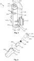
- the teat cup illustrated in Fig. 1 and Fig. 2 of the accompanying drawings is one of four similar teat cups of a milking cluster used for milking a cow and which is connected to milking equipment.
- Each teat cup 1 comprises a hollow generally cylindrical shell 2 supporting a flexible liner 3 in spaced relation with the shell.
- the liner has a cylindrical barrel portion 4 sealed to the shell adjacent the bottom, discharge end 5 and adjacent the top or head end 6 of the cup.
- the liner has a head portion 7 which engages, via a skirt portion 8, about the outside of the shell in order to seal the shell to the head end of the barrel, and which projects above the adjacent end of the shell.
- the head 7 of the liner is formed with a mouth 9 permitting access to the interior of the liner.
- the head of the liner is formed with an internal annular cavity 10 which, when an animal's teat is inserted into the cup through the mouth 9, forms a void or space 11 between the side of the teat and the head.
- the teat cup has a central axis 25 along the length of the teat cup, between the head portion 7 and the discharge end 5 of the teat cup, and the teat is typically aligns with the central axis 25 when in the teat cup.
- the liner has a discharge passageway 12 communicating with a flexible, short milk tube 13 which connects the teat cup to a clawpiece (not shown) of the milking cluster and via which vacuum is applied to the inside of the liner for removing, from the cup, milk discharged by the teat during the milking cycle.
- the shell 2 may be moulded from rigid plastics material whilst the liner 3 may be moulded from resilient plastic, synthetic rubber or silicone.
- Integrally moulded with the shell is an inlet tube 14 for connecting the space 15 between the shell 2 and the liner 3, via the clawpiece, to a suitable source for alternately supplying vacuum pulses and venting the space 15 to atmosphere in order to cause the liner to flex against the teat and stimulate milking of an animal to which the teat cup is fitted.
- the inlet tube has a spigot 16 at its inlet end to which is attached a flexible pipe (not shown) coupling the inlet tube to the clawpiece.
- an injector 18 for injecting fluid into the cavity 10 in the head portion of the liner.
- the injector 18 comprises a non-return valve 19 for controlling delivery of fluid into the injector, and a coupling 20 for connecting a fluid delivery tube 21 to the injector.
- the injector is mounted to the shell 2 and protrudes through the liner to the inside of the head portion 7. It is prevented from moving upwardly in the head portion by a shoulder 24 adjacent the mouth of the liner and it is also indexed in predetermined alignment with the teat cup.
- the injector 18 is supplied with fluid, via the non-return valve 19, by the delivery tube 21 which is mounted internally of the shell 2 and connects a fluid inlet spigot 35 adjacent the discharge end 5 of the teat cup to the inlet of the injector 18.
- the fluid inlet spigot 35 is moulded integrally with the shell juxtaposed and on the inside of the inlet passage 14. Downstream of the inlet spigot, the delivery tube snaps into a part-circular groove 36 moulded along the inside wall of the shell 2.
- the arrangement is such that the radial inner surface of the delivery tube is substantially flush with the inside surface of the shell 2 so as not to interfere with the flexing motion of the liner 3 during milking.
- the delivery tube is conveniently moulded from stainless steel.
- a cylindrical weight 40 which assists in causing the lightweight plastic teat cups to fall into an inverted position with their heads downwardly upon take-off of the milking cluster.
- the cylindrical weight 40 is preferably made from stainless steel and is sealed to the outside of the shell by O-rings 41 retained in annular grooves moulded in the outside of the shell.
- the construction of the teat cup facilitates its assembly, and replacement of the liner 3 when necessary, and also, replacement of the cylindrical weight 40 to suit specific requirements of milking if more or less weight is required.
- the shell 2 is supplied with the delivery tube 21 mounted in the groove 36 along the inside of the shell.
- the appropriate cylindrical weight is mounted about the outside of the shell, over the O-rings 41 and against the moulded shoulder 39 and then the liner is assembled to the shell.
- the liner 3 is assembled by fitting the discharge end of the liner through the shell 2 from its head end. As the skirt portion 8 of the head of the liner engages about the head end of the shell, the adjacent end of the delivery tube 21 is automatically inserted into the inlet opening of the injector 18. The inlet end of the delivery tube may be chamfered to facilitate entry into the inlet of the injector.
- Fig 3 shows a perspective diagram of the injector 18, which comprises a housing 100 having a lower end where fins 110, 111 are located and an upper end where nozzles 131 and 132 are located. There are four fins arranged in two pairs, each pair having one fin 110 and one fin 111 which are spaced apart from one another to define a groove 120. Each groove 120 is aligned along a length of the injector 18, the length being between the upper and lower ends. The grooves 120 oppose one another, and allow the injector 18 to be slotted into a slot formed in the end of the shell 2 nearest the head portion of the liner 3. This keeps the injector in the same orientation as the shell and therefore the teat cup.
- the nozzles comprises a first nozzle 131 for injecting fluid substantially horizontally into the head portion 7 of the teat cup, and a second nozzle 132 for injecting fluid downwardly towards the milk discharge passageway 12 of the teat cup.
- the fluid from the first nozzle 131 is illustratively shown in Fig. 1 as fluid FLT
- the fluid from the second nozzle 132 is illustratively shown in Fig. 1 as fluid FLF.
- the top part of the injector 18 engages through a hole in the liner 3 so that the first and second nozzles are inside the head portion 7 of the liner.
- the first nozzle 131 has a single exit hole 141 through which the fluid FLT exits
- the second nozzle 132 has three exit holes 142 through which the fluid FLF exits.
- the three exit holes 142 are spaced apart from one another along a circumference around the central axis 25, and inject fluid in diverging directions to strike different parts of the animal's teat around a circumference of the animal's teat.
- the diverging directions all make substantially the same angle with the central axis 25.
- the number of exit holes for each nozzle may vary in alternate embodiments, and more than two nozzles may be provided in some embodiments to direct fluids in a variety of differing directions.
- the exploded diagram of Fig. 4 shows the constituent parts of the injector 18, specifically the housing 100, a diverter valve ball 210, an insert 220, a return spring 230, a non-return valve ball 240, and a bung 250.
- the housing 100 and the insert 220 are moulded from a rigid plastics material.
- the diverter valve ball 210, return spring 230, and non-return valve ball 240 are formed of stainless steel, and the bung 250 is moulded from rubber.
- the non-return valve ball 240 is connected to the insert 220 by the return spring 230. Then, the diverter ball valve 210 is dropped into a cylindrical cavity 113 within the housing 100, and the insert 220 is slid into the cylindrical cavity 113 behind the diverter valve ball. The insert 220 and the end of the cylindrical cavity 113 together define a diverter valve cavity 310 (see Fig. 5 ) within which the diverter ball valve 210 is free to move. The diverter valve cavity 310 and the diverter ball valve 210 together constitute a gravity biased diverter. Finally, the rubber bung 250 is pushed into the cylindrical cavity 113 until a base 254 of the rubber bung abuts against the entry to the cylindrical cavity 113.
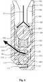
- FIG. 5 and Fig. 6 Two cross-sectional views of the assembled injector 18 are shown in Fig. 5 and Fig. 6 . These cross-sectional views are both taken looking in from plane XS1 marked on Fig. 3 .
- the injector 18 is shown in a normal orientation corresponding to when the mouth of the teat cup is above the milk discharge passageway. Such an orientation corresponds to the orientation of the teat cup when the teat cup is attached to an animal's teat for milking.
- the diverter valve cavity 310 contains the diverter ball valve 210.
- the diverter valve cavity 310 comprises a first valve seating 312 leading to a first passageway 151, and a second valve seating 314 leading to a second passageway 152.
- the first passageway 151 leads to the exit hole of the first nozzle 131, and the second passageway 152 leads to the exit holes of the second nozzle 132.
- the diverter ball valve 210 Since the injector 18 is in the normal orientation, the diverter ball valve 210 has moved in the direction DR1 under the influence of gravity, to abut against the second valve seating 314, and prevent fluid in the diverter valve cavity 310 from entering the second passageway 152. Accordingly, any fluid that enters the diverter valve cavity 310 is forced to exit the diverter valve cavity 310 via the first passageway 151 and the first nozzle 131, rather than the second passageway 152 and second nozzle 132.
- the rubber bung 250 comprises an inlet 255 which forms the coupling 20 for connecting the delivery tube 21 (refer to Fig. 1 ).
- the inlet 255 comprises an entrance funnel 252 to ease the insertion of the delivery tube 21 into the inlet 255.
- the inlet 255 grips the delivery tube and forms a seal therewith to prevent leakage of fluids supplied by the delivery tube 21.
- the rubber bung also comprises a valve seating 342 at an end of the inlet 255 opposite the entrance funnel 252.
- the valve seating 342 forms part of a non-return valve cavity 340 that is defined by a space inside the cylindrical cavity 113 between the insert 220 and the rubber bung 250.
- the non-return valve cavity 340 together with the return spring 230, non-return valve ball 240, and rubber bung 250, forms the non-return valve 19.
- the return spring 230 biases the non-return valve ball 240 towards the valve seating 342, such that the non-return valve ball 240 normally presses against the valve seating 342 to keep the inlet 255 closed.
- the insert 220 comprises a slot 400 (see Figs. 4 and 7 ) which provides a path for fluids from the non-return valve cavity 340 to the diverter valve cavity 310.
- the fluid FLT reaches the diverter valve cavity 310 and is diverted to the first passageway 151 by the diverter valve ball 210, which is blocking off the second passageway 152 by virtue of the orientation of the injector 18 and teat cup 1.
- the fluid FLT moves through the first passageway 151 and exits the first nozzle 131 substantially perpendicular to the length of the housing 100 and the central axis 25.
- the fluid FLT is treatment fluid that is delivered to the injector 18 by the delivery tube 21, and that is directed horizontally towards the teat of the animal from the first nozzle 131 by the injector 18.
- the injector 18 is shown in an inverted orientation corresponding to when the milk discharge passageway of the teat cup is above the mouth.
- Such an orientation corresponds to the orientation of the teat cup once the teat cup has been withdrawn from the teat and allowed to fall into an inverted position.
- the diverter ball valve 210 Since the injector 18 is in the inverted orientation, the diverter ball valve 210 has moved in the direction DR3 under the influence of gravity, to abut against the first valve seating 312, and prevent fluid in the diverter valve cavity 310 from entering the first passageway 151. Accordingly, any fluid that enters the diverter valve cavity 310 is forced to exit the diverter valve cavity 310 via the second passageway 152 and the second nozzle 132, rather than the first passageway 151 and first nozzle 131.
- the fluid FLF travels from the non-return valve cavity 340 to the diverter valve cavity 310 via the slot 400 (see Fig. 4 and Fig. 7 ), and is diverted to the second passageway 152 by the diverter valve ball 210, which is blocking off the first passageway 151 by virtue of the orientation of the injector 18 and teat cup 1.
- the fluid FLF moves through the second passageway 152 and exits the second nozzle 131 in a direction towards the milk discharge passageway, since the second nozzle 131 points towards the milk discharge passageway.
- the fluid FLF is flushing fluid that is delivered to the injector 18 by the delivery tube 21, and that is directed upwardly towards the milk discharge passageway of the teat cup, to help cleanse the barrel of the liner 3.
- FIG. 7 Another cross-sectional view of the assembled injector 18 is shown in Fig. 7 , which shows a view looking in from plane XS2 marked on Fig. 3 .
- the non-return valve is show in its rest position where the delivery tube 21 is not supplying any fluid, so that the non-return valve ball 240 is fully urged against the valve seat 342 by the return spring 230, to prevent any back-flow of fluids from the non-return valve cavity 340 into the delivery tube 21.
- Fig. 7 the paths FP that fluids take between the non-return valve cavity and the diverter valve cavity are visible.
- the paths FP are provided by slots 400 positioned on opposing sides of the insert 220, such that they are symmetrical with one another about the diverter valve ball 220.
- One of the slots 400 is visible in Fig. 4 . It can be seen that the paths FP open into the diverter valve cavity 310 substantially mid-way between the first and second valve seatings 312 and 314.
- any inflow of fluid into the diverter valve cavity 310 via the paths FP will impact the diverter valve ball 220 and tend to force the diverter valve ball 220 even harder against whichever one of the first and second valve seatings it is currently resting against, helping to assure that the diverter valve ball prevents any leakage of fluid into the wrong nozzle.
- the angle between the fluid FLT and the central axis 25, which is 90 degrees in this embodiment, is larger than the angle between the fluid FLF and the central axis 25, which is 45 degrees in this embodiment.
- the first and second nozzles may be configured inject fluid at angles other than 90 degrees and 45 degrees.
- the first nozzle may be configured to direct the fluid FLT slightly upwardly, rather than at 90 degrees, so that the fluid FLT reaches even higher up the teat of the animal.
Landscapes
- Life Sciences & Earth Sciences (AREA)
- Animal Husbandry (AREA)
- Environmental Sciences (AREA)
- Dairy Products (AREA)
- Infusion, Injection, And Reservoir Apparatuses (AREA)
- Meat, Egg Or Seafood Products (AREA)
Claims (15)
- Gobelet trayeur (1) comprenant un manchon flexible (3) pour entrer en prise autour d'un trayon d'un animal à traire, le manchon ayant une portion de tête (7) au niveau d'une extrémité du manchon et une voie de passage d'évacuation de lait (12) au niveau d'une autre extrémité (5) du manchon, dans lequel la portion de tête (7) est pourvue d'un embout (9) par l'intermédiaire duquel le trayon peut entrer en prise avec le manchon, et d'un injecteur (18) pour injecter un fluide dans la portion de tête du manchon,
caractérisé en ce que l'injecteur (18) comprend un déviateur sollicité par la pesanteur (210) qui commande, sur la base d'une orientation du gobelet trayeur, une direction d'injection dans laquelle le fluide est injecté dans la portion de tête. - Gobelet trayeur selon la revendication 1, dans lequel la commande de la direction d'injection comprend le changement de la direction d'injection entre des première et seconde directions (FLT, FLF) sur le base de la position dans laquelle le gobelet trayeur est orienté.
- Gobelet trayeur selon la revendication 2, dans lequel l'injecteur comprend des première et seconde buses (131, 132) qui injectent le fluide de traitement dans la tête du manchon dans les première et seconde directions (FLT, FLF) respectivement.
- Gobelet trayeur selon la revendication 3, dans lequel la première direction (FLT) est perpendiculaire à une longueur du manchon entre la portion de tête (7) et la voie de passage d'évacuation de lait (5), et dans lequel la seconde direction (FLF) forme un angle vers la voie de passage d'évacuation de lait (5) du manchon.
- Gobelet trayeur selon la revendication 3 ou 4, dans lequel le déviateur sollicité par la pesanteur (210) est configuré pour dévier le fluide vers la première buse (131) plutôt que vers la seconde buse (132) lorsque le gobelet trayeur est dans une orientation normale avec l'embout (9) au-dessus de la voie de passage d'évacuation de lait (5) et pour dévier le fluide vers la seconde buse (132) plutôt que vers la première buse lorsque le gobelet trayeur est dans une orientation inversée avec l'embout (9) en dessous de la voie de passage d'évacuation de lait (5).
- Gobelet trayeur selon la revendication 3, 4 ou 5, dans lequel le déviateur sollicité par la pesanteur comprend un élément de vanne (210) qui se déplace sous l'influence de la pesanteur pour débloquer sélectivement l'une d'une première voie de passage (151) vers la première buse (131) et d'une seconde voie de passage (152) vers la seconde buse (132).
- Gobelet trayeur selon la revendication 6, dans lequel l'élément de vanne est une bille (210) qui se déplace sous l'influence de la pesanteur entre un premier siège de vanne (312) au niveau d'une entrée dans la première voie de passage (151) et un second siège de vanne (314) au niveau d'une entrée dans la seconde voie de passage (152).
- Gobelet trayeur selon la revendication 7, dans lequel la bille (210) est retenue dans une cavité de vanne de déviateur (310) ayant les premier et second sièges de vanne au niveau d'extrémités opposées de la cavité de vanne de déviateur, et dans lequel au moins un trajet (FP) est prévu pour que des fluides entrent dans la cavité de vanne de déviateur (310) sensiblement à mi-chemin entre les premier et second sièges de vanne (312, 314).
- Gobelet trayeur selon l'une quelconque des revendications 3 à 8, dans lequel au moins l'une des première et seconde buses (131, 132) comprend une pluralité de trous de sortie (141, 142) à travers lesquels le fluide est injecté.
- Gobelet trayeur selon l'une quelconque des revendications 2 à 9, dans lequel la première direction (FLF) forme un premier angle avec un axe central (25) du manchon, et la seconde direction (FLT) forme un second angle avec l'axe central (25) du manchon, dans lequel l'axe central (25) du manchon va de l'embout (9) jusqu'à la voie de passage d'évacuation de lait (5), et dans lequel le premier angle est plus grand que le second angle.
- Gobelet trayeur selon la revendication 10 lorsqu'elle est jointe à la revendication 9, dans lequel les trous de sortie (142) de chaque pluralité de trous de sortie sont espacés les uns des autres le long d'une circonférence autour de l'axe central.
- Gobelet trayeur selon l'une quelconque des revendications précédentes, comprenant en outre un tube de distribution de fluide (21) qui est raccordé à l'injecteur (18) et qui permet une distribution de fluide à l'injecteur, et une vanne antiretour (19) montée dans l'injecteur qui commande la distribution de fluide depuis le tube de distribution de fluide.
- Gobelet trayeur selon la revendication 12, dans lequel l'injecteur (18) comprend un logement ayant le déviateur sollicité par la pesanteur (210) et la vanne antiretour (19), la vanne antiretour étant montée au niveau d'une admission de l'injecteur où le tube de distribution de fluide (21) est raccordé à l'injecteur.
- Gobelet trayeur selon la revendication 13, dans lequel la vanne antiretour (19) comprend un ressort de rappel (230) qui est dimensionné pour admettre le fluide dans le déviateur sollicité par la pesanteur lorsqu'une quantité supérieure à un différentiel de pression de fluide prédéterminé se produit entre la portion de tête (7) du manchon et le tube de distribution de fluide (21).
- Procédé de traite d'un animal à l'aide du gobelet trayeur (1) de l'une quelconque des revendications précédentes, le procédé comprenant l'application du gobelet trayeur à un trayon d'un animal, l'application d'un vide au manchon (3) via la voie de passage d'évacuation de lait (5) pendant un cycle de traite pour aider à l'extraction de lait, l'injection d'un fluide de traitement dans la portion de tête (7) via l'injecteur (18) une fois que le cycle de traite est achevé, le retrait du gobelet trayeur du trayon et le fait de laisser le gobelet trayeur tomber dans une position inversée avec la portion de tête (7) en dessous de la voie de passage d'évacuation de lait (5), et l'injection d'un fluide de rinçage via l'injecteur (18) dans une portion de cylindre (4) du manchon entre la portion de tête (7) et la voie de passage d'évacuation de lait (5) lorsque le gobelet trayeur est dans la position inversée.
Priority Applications (1)
| Application Number | Priority Date | Filing Date | Title |
|---|---|---|---|
| PL15713572T PL3122174T3 (pl) | 2014-03-28 | 2015-03-20 | Kubki udojowe ze środkami dyszy |
Applications Claiming Priority (2)
| Application Number | Priority Date | Filing Date | Title |
|---|---|---|---|
| GB201405611A GB201405611D0 (en) | 2014-03-28 | 2014-03-28 | A teat cup |
| PCT/GB2015/050838 WO2015145116A1 (fr) | 2014-03-28 | 2015-03-20 | Gobelet-trayeur avec moyen buse |
Publications (2)
| Publication Number | Publication Date |
|---|---|
| EP3122174A1 EP3122174A1 (fr) | 2017-02-01 |
| EP3122174B1 true EP3122174B1 (fr) | 2018-05-09 |
Family
ID=50737609
Family Applications (1)
| Application Number | Title | Priority Date | Filing Date |
|---|---|---|---|
| EP15713572.4A Active EP3122174B1 (fr) | 2014-03-28 | 2015-03-20 | Gobelet-trayeur avec moyen buse |
Country Status (8)
| Country | Link |
|---|---|
| US (1) | US10413915B2 (fr) |
| EP (1) | EP3122174B1 (fr) |
| AU (1) | AU2015238033B2 (fr) |
| BR (1) | BR112016022356B1 (fr) |
| GB (1) | GB201405611D0 (fr) |
| PL (1) | PL3122174T3 (fr) |
| TR (1) | TR201807384T4 (fr) |
| WO (1) | WO2015145116A1 (fr) |
Families Citing this family (12)
| Publication number | Priority date | Publication date | Assignee | Title |
|---|---|---|---|---|
| US8117989B2 (en) | 2008-06-27 | 2012-02-21 | Gea Farm Technologies, Inc. | Milk tube dome with flow controller |
| US8033247B2 (en) | 2004-06-12 | 2011-10-11 | Gea Farm Technologies, Inc. | Automatic dairy animal milker unit backflusher and teat dip applicator system and method |
| US10874084B2 (en) | 2004-06-12 | 2020-12-29 | Gea Farm Technologies, Inc. | Safety valve for a dairy system component |
| US8770146B2 (en) | 2009-09-04 | 2014-07-08 | Gea Farm Technologies, Inc. | Methods and apparatus for applying teat dip to a dairy animal |
| US11723341B2 (en) | 2009-09-04 | 2023-08-15 | Gea Farm Technologies, Inc. | Safety valve for an automated milker unit backflushing and teat dip applicator system |
| US20120097107A1 (en) | 2010-02-22 | 2012-04-26 | Gea Farm Technologies, Inc. | Dairy animal milking preparation system and methods |
| DE102013114595A1 (de) | 2013-12-20 | 2015-06-25 | Gea Farm Technologies Gmbh | Sicherheitsventil |
| US9526224B2 (en) | 2013-12-20 | 2016-12-27 | Gea Farm Technologies Gmbh | Safety valve device |
| US10217408B2 (en) * | 2015-11-11 | 2019-02-26 | Joled Inc. | Display device, display device correction method, display device manufacturing method, and display device display method |
| DE102016108300A1 (de) | 2016-05-04 | 2017-11-09 | Gea Farm Technologies Gmbh | Sicherheitsventil |
| GB2564489A (en) * | 2017-07-14 | 2019-01-16 | An Udder Ip Company Ltd | A milking cluster for milking an animal |
| US11206805B2 (en) | 2017-11-03 | 2021-12-28 | Gea Farm Technologies Gmbh | Automated milking system safety valve arrangement |
Family Cites Families (16)
| Publication number | Priority date | Publication date | Assignee | Title |
|---|---|---|---|---|
| US2731300A (en) * | 1953-03-09 | 1956-01-17 | Raymond K Jansen | Cow washer |
| US3545488A (en) * | 1967-07-19 | 1970-12-08 | Risdon Mfg Co | Dip tubes for aerosol valve assemblies |
| GB1497271A (en) * | 1974-01-18 | 1978-01-05 | Spectus Oil Burners | Multi-fluid injectors |
| US4392507A (en) * | 1981-05-15 | 1983-07-12 | Stant Inc. | Two-stage pressure relief valve |
| KR950009345B1 (ko) * | 1992-12-24 | 1995-08-21 | 정상현 | 액상저장용기의 유출로 개폐변환밸브 |
| SE0202988D0 (sv) * | 2002-03-15 | 2002-10-10 | Delaval Holding Ab | A method and an arrangement at a dairy farm |
| SE526165C2 (sv) * | 2003-04-23 | 2005-07-19 | Hugo Nilsson | Självstängande utmatningsanordning för vätska |
| US6935270B2 (en) * | 2003-08-29 | 2005-08-30 | Delaval, Inc. | Milking and application teat cup, system, and method |
| GB0408968D0 (en) * | 2004-04-22 | 2004-05-26 | Duke James R J | Milking equipment |
| WO2005072516A1 (fr) * | 2004-01-30 | 2005-08-11 | James Richard John Duke | Materiel de traite |
| US20090165724A1 (en) * | 2004-09-14 | 2009-07-02 | Westfaliasurge Gmbh | Teat Cup and Method for Bringing a Fluid into Contact with the Teat of an Animal |
| US20060090792A1 (en) * | 2004-11-02 | 2006-05-04 | Richard Tamian | Multiaxial vibration valve |
| GB0518976D0 (en) * | 2005-09-16 | 2005-10-26 | Duke James R J | Teat cup |
| FR2894853B1 (fr) * | 2005-12-15 | 2008-03-14 | Sidel Sas | Dispositif de projection d'un liquide |
| DE102006053602A1 (de) * | 2006-11-14 | 2008-05-15 | Jakob Maier | Reinigungsanlage für Melkbecher |
| NL1037240C2 (nl) * | 2009-08-31 | 2011-03-01 | Lely Patent Nv | Voorbehandelingsspeenbeker. |
-
2014
- 2014-03-28 GB GB201405611A patent/GB201405611D0/en not_active Ceased
-
2015
- 2015-03-20 TR TR2018/07384T patent/TR201807384T4/tr unknown
- 2015-03-20 EP EP15713572.4A patent/EP3122174B1/fr active Active
- 2015-03-20 US US15/123,881 patent/US10413915B2/en active Active
- 2015-03-20 PL PL15713572T patent/PL3122174T3/pl unknown
- 2015-03-20 BR BR112016022356-0A patent/BR112016022356B1/pt active IP Right Grant
- 2015-03-20 AU AU2015238033A patent/AU2015238033B2/en active Active
- 2015-03-20 WO PCT/GB2015/050838 patent/WO2015145116A1/fr active Application Filing
Non-Patent Citations (1)
| Title |
|---|
| None * |
Also Published As
| Publication number | Publication date |
|---|---|
| TR201807384T4 (tr) | 2018-06-21 |
| PL3122174T3 (pl) | 2018-08-31 |
| BR112016022356B1 (pt) | 2021-03-09 |
| NZ723429A (en) | 2021-03-26 |
| GB201405611D0 (en) | 2014-05-14 |
| US10413915B2 (en) | 2019-09-17 |
| WO2015145116A1 (fr) | 2015-10-01 |
| AU2015238033A1 (en) | 2016-09-08 |
| US20170014837A1 (en) | 2017-01-19 |
| AU2015238033B2 (en) | 2018-02-22 |
| EP3122174A1 (fr) | 2017-02-01 |
Similar Documents
| Publication | Publication Date | Title |
|---|---|---|
| EP3122174B1 (fr) | Gobelet-trayeur avec moyen buse | |
| EP1933616B2 (fr) | Manchon trayeur | |
| EP2876996B1 (fr) | Équipement de traite | |
| US7963249B2 (en) | Milking equipment and method | |
| US9504226B2 (en) | Methods and apparatus for applying teat dip to a dairy animal | |
| ES2438970T5 (es) | Equipo de ordeño | |
| US20080083373A1 (en) | Milking device provided with cleansing means | |
| WO2005072516A1 (fr) | Materiel de traite | |
| DK173139B1 (da) | Kombihane | |
| WO2015118336A1 (fr) | Équipement de traite | |
| NZ723429B2 (en) | A teat cup with nozzle means | |
| EP2777387B1 (fr) | Procédés et appareil pour l'application de trempage des trayons d'un animal laitier | |
| US20210076632A1 (en) | A milking cluster for milking an animal |
Legal Events
| Date | Code | Title | Description |
|---|---|---|---|
| STAA | Information on the status of an ep patent application or granted ep patent |
Free format text: STATUS: THE INTERNATIONAL PUBLICATION HAS BEEN MADE |
|
| PUAI | Public reference made under article 153(3) epc to a published international application that has entered the european phase |
Free format text: ORIGINAL CODE: 0009012 |
|
| STAA | Information on the status of an ep patent application or granted ep patent |
Free format text: STATUS: REQUEST FOR EXAMINATION WAS MADE |
|
| 17P | Request for examination filed |
Effective date: 20161007 |
|
| AK | Designated contracting states |
Kind code of ref document: A1 Designated state(s): AL AT BE BG CH CY CZ DE DK EE ES FI FR GB GR HR HU IE IS IT LI LT LU LV MC MK MT NL NO PL PT RO RS SE SI SK SM TR |
|
| AX | Request for extension of the european patent |
Extension state: BA ME |
|
| DAV | Request for validation of the european patent (deleted) | ||
| DAX | Request for extension of the european patent (deleted) | ||
| GRAP | Despatch of communication of intention to grant a patent |
Free format text: ORIGINAL CODE: EPIDOSNIGR1 |
|
| STAA | Information on the status of an ep patent application or granted ep patent |
Free format text: STATUS: GRANT OF PATENT IS INTENDED |
|
| INTG | Intention to grant announced |
Effective date: 20170928 |
|
| GRAS | Grant fee paid |
Free format text: ORIGINAL CODE: EPIDOSNIGR3 |
|
| GRAA | (expected) grant |
Free format text: ORIGINAL CODE: 0009210 |
|
| STAA | Information on the status of an ep patent application or granted ep patent |
Free format text: STATUS: THE PATENT HAS BEEN GRANTED |
|
| AK | Designated contracting states |
Kind code of ref document: B1 Designated state(s): AL AT BE BG CH CY CZ DE DK EE ES FI FR GB GR HR HU IE IS IT LI LT LU LV MC MK MT NL NO PL PT RO RS SE SI SK SM TR |
|
| REG | Reference to a national code |
Ref country code: GB Ref legal event code: FG4D |
|
| REG | Reference to a national code |
Ref country code: CH Ref legal event code: EP Ref country code: AT Ref legal event code: REF Ref document number: 996660 Country of ref document: AT Kind code of ref document: T Effective date: 20180515 |
|
| REG | Reference to a national code |
Ref country code: IE Ref legal event code: FG4D |
|
| REG | Reference to a national code |
Ref country code: DE Ref legal event code: R096 Ref document number: 602015010936 Country of ref document: DE |
|
| REG | Reference to a national code |
Ref country code: SE Ref legal event code: TRGR |
|
| REG | Reference to a national code |
Ref country code: NL Ref legal event code: FP |
|
| REG | Reference to a national code |
Ref country code: LT Ref legal event code: MG4D |
|
| PG25 | Lapsed in a contracting state [announced via postgrant information from national office to epo] |
Ref country code: LT Free format text: LAPSE BECAUSE OF FAILURE TO SUBMIT A TRANSLATION OF THE DESCRIPTION OR TO PAY THE FEE WITHIN THE PRESCRIBED TIME-LIMIT Effective date: 20180509 Ref country code: NO Free format text: LAPSE BECAUSE OF FAILURE TO SUBMIT A TRANSLATION OF THE DESCRIPTION OR TO PAY THE FEE WITHIN THE PRESCRIBED TIME-LIMIT Effective date: 20180809 Ref country code: FI Free format text: LAPSE BECAUSE OF FAILURE TO SUBMIT A TRANSLATION OF THE DESCRIPTION OR TO PAY THE FEE WITHIN THE PRESCRIBED TIME-LIMIT Effective date: 20180509 Ref country code: ES Free format text: LAPSE BECAUSE OF FAILURE TO SUBMIT A TRANSLATION OF THE DESCRIPTION OR TO PAY THE FEE WITHIN THE PRESCRIBED TIME-LIMIT Effective date: 20180509 Ref country code: BG Free format text: LAPSE BECAUSE OF FAILURE TO SUBMIT A TRANSLATION OF THE DESCRIPTION OR TO PAY THE FEE WITHIN THE PRESCRIBED TIME-LIMIT Effective date: 20180809 |
|
| PG25 | Lapsed in a contracting state [announced via postgrant information from national office to epo] |
Ref country code: GR Free format text: LAPSE BECAUSE OF FAILURE TO SUBMIT A TRANSLATION OF THE DESCRIPTION OR TO PAY THE FEE WITHIN THE PRESCRIBED TIME-LIMIT Effective date: 20180810 Ref country code: RS Free format text: LAPSE BECAUSE OF FAILURE TO SUBMIT A TRANSLATION OF THE DESCRIPTION OR TO PAY THE FEE WITHIN THE PRESCRIBED TIME-LIMIT Effective date: 20180509 Ref country code: LV Free format text: LAPSE BECAUSE OF FAILURE TO SUBMIT A TRANSLATION OF THE DESCRIPTION OR TO PAY THE FEE WITHIN THE PRESCRIBED TIME-LIMIT Effective date: 20180509 Ref country code: HR Free format text: LAPSE BECAUSE OF FAILURE TO SUBMIT A TRANSLATION OF THE DESCRIPTION OR TO PAY THE FEE WITHIN THE PRESCRIBED TIME-LIMIT Effective date: 20180509 |
|
| REG | Reference to a national code |
Ref country code: AT Ref legal event code: MK05 Ref document number: 996660 Country of ref document: AT Kind code of ref document: T Effective date: 20180509 |
|
| PG25 | Lapsed in a contracting state [announced via postgrant information from national office to epo] |
Ref country code: AT Free format text: LAPSE BECAUSE OF FAILURE TO SUBMIT A TRANSLATION OF THE DESCRIPTION OR TO PAY THE FEE WITHIN THE PRESCRIBED TIME-LIMIT Effective date: 20180509 Ref country code: EE Free format text: LAPSE BECAUSE OF FAILURE TO SUBMIT A TRANSLATION OF THE DESCRIPTION OR TO PAY THE FEE WITHIN THE PRESCRIBED TIME-LIMIT Effective date: 20180509 Ref country code: DK Free format text: LAPSE BECAUSE OF FAILURE TO SUBMIT A TRANSLATION OF THE DESCRIPTION OR TO PAY THE FEE WITHIN THE PRESCRIBED TIME-LIMIT Effective date: 20180509 Ref country code: RO Free format text: LAPSE BECAUSE OF FAILURE TO SUBMIT A TRANSLATION OF THE DESCRIPTION OR TO PAY THE FEE WITHIN THE PRESCRIBED TIME-LIMIT Effective date: 20180509 Ref country code: SK Free format text: LAPSE BECAUSE OF FAILURE TO SUBMIT A TRANSLATION OF THE DESCRIPTION OR TO PAY THE FEE WITHIN THE PRESCRIBED TIME-LIMIT Effective date: 20180509 Ref country code: CZ Free format text: LAPSE BECAUSE OF FAILURE TO SUBMIT A TRANSLATION OF THE DESCRIPTION OR TO PAY THE FEE WITHIN THE PRESCRIBED TIME-LIMIT Effective date: 20180509 |
|
| REG | Reference to a national code |
Ref country code: DE Ref legal event code: R097 Ref document number: 602015010936 Country of ref document: DE |
|
| PG25 | Lapsed in a contracting state [announced via postgrant information from national office to epo] |
Ref country code: IT Free format text: LAPSE BECAUSE OF FAILURE TO SUBMIT A TRANSLATION OF THE DESCRIPTION OR TO PAY THE FEE WITHIN THE PRESCRIBED TIME-LIMIT Effective date: 20180509 Ref country code: SM Free format text: LAPSE BECAUSE OF FAILURE TO SUBMIT A TRANSLATION OF THE DESCRIPTION OR TO PAY THE FEE WITHIN THE PRESCRIBED TIME-LIMIT Effective date: 20180509 |
|
| PLBE | No opposition filed within time limit |
Free format text: ORIGINAL CODE: 0009261 |
|
| STAA | Information on the status of an ep patent application or granted ep patent |
Free format text: STATUS: NO OPPOSITION FILED WITHIN TIME LIMIT |
|
| 26N | No opposition filed |
Effective date: 20190212 |
|
| PG25 | Lapsed in a contracting state [announced via postgrant information from national office to epo] |
Ref country code: SI Free format text: LAPSE BECAUSE OF FAILURE TO SUBMIT A TRANSLATION OF THE DESCRIPTION OR TO PAY THE FEE WITHIN THE PRESCRIBED TIME-LIMIT Effective date: 20180509 |
|
| PG25 | Lapsed in a contracting state [announced via postgrant information from national office to epo] |
Ref country code: MC Free format text: LAPSE BECAUSE OF FAILURE TO SUBMIT A TRANSLATION OF THE DESCRIPTION OR TO PAY THE FEE WITHIN THE PRESCRIBED TIME-LIMIT Effective date: 20180509 |
|
| REG | Reference to a national code |
Ref country code: CH Ref legal event code: PL |
|
| PG25 | Lapsed in a contracting state [announced via postgrant information from national office to epo] |
Ref country code: LU Free format text: LAPSE BECAUSE OF NON-PAYMENT OF DUE FEES Effective date: 20190320 Ref country code: AL Free format text: LAPSE BECAUSE OF FAILURE TO SUBMIT A TRANSLATION OF THE DESCRIPTION OR TO PAY THE FEE WITHIN THE PRESCRIBED TIME-LIMIT Effective date: 20180509 |
|
| REG | Reference to a national code |
Ref country code: BE Ref legal event code: MM Effective date: 20190331 |
|
| PG25 | Lapsed in a contracting state [announced via postgrant information from national office to epo] |
Ref country code: CH Free format text: LAPSE BECAUSE OF NON-PAYMENT OF DUE FEES Effective date: 20190331 Ref country code: IE Free format text: LAPSE BECAUSE OF NON-PAYMENT OF DUE FEES Effective date: 20190320 Ref country code: LI Free format text: LAPSE BECAUSE OF NON-PAYMENT OF DUE FEES Effective date: 20190331 |
|
| PG25 | Lapsed in a contracting state [announced via postgrant information from national office to epo] |
Ref country code: BE Free format text: LAPSE BECAUSE OF NON-PAYMENT OF DUE FEES Effective date: 20190331 Ref country code: FR Free format text: LAPSE BECAUSE OF NON-PAYMENT OF DUE FEES Effective date: 20190331 |
|
| PG25 | Lapsed in a contracting state [announced via postgrant information from national office to epo] |
Ref country code: MT Free format text: LAPSE BECAUSE OF NON-PAYMENT OF DUE FEES Effective date: 20190320 Ref country code: PT Free format text: LAPSE BECAUSE OF FAILURE TO SUBMIT A TRANSLATION OF THE DESCRIPTION OR TO PAY THE FEE WITHIN THE PRESCRIBED TIME-LIMIT Effective date: 20180910 |
|
| PG25 | Lapsed in a contracting state [announced via postgrant information from national office to epo] |
Ref country code: CY Free format text: LAPSE BECAUSE OF FAILURE TO SUBMIT A TRANSLATION OF THE DESCRIPTION OR TO PAY THE FEE WITHIN THE PRESCRIBED TIME-LIMIT Effective date: 20180509 |
|
| PG25 | Lapsed in a contracting state [announced via postgrant information from national office to epo] |
Ref country code: IS Free format text: LAPSE BECAUSE OF FAILURE TO SUBMIT A TRANSLATION OF THE DESCRIPTION OR TO PAY THE FEE WITHIN THE PRESCRIBED TIME-LIMIT Effective date: 20180909 |
|
| PG25 | Lapsed in a contracting state [announced via postgrant information from national office to epo] |
Ref country code: HU Free format text: LAPSE BECAUSE OF FAILURE TO SUBMIT A TRANSLATION OF THE DESCRIPTION OR TO PAY THE FEE WITHIN THE PRESCRIBED TIME-LIMIT; INVALID AB INITIO Effective date: 20150320 |
|
| PG25 | Lapsed in a contracting state [announced via postgrant information from national office to epo] |
Ref country code: MK Free format text: LAPSE BECAUSE OF FAILURE TO SUBMIT A TRANSLATION OF THE DESCRIPTION OR TO PAY THE FEE WITHIN THE PRESCRIBED TIME-LIMIT Effective date: 20180509 |
|
| PGFP | Annual fee paid to national office [announced via postgrant information from national office to epo] |
Ref country code: NL Payment date: 20240320 Year of fee payment: 10 |
|
| PGFP | Annual fee paid to national office [announced via postgrant information from national office to epo] |
Ref country code: DE Payment date: 20240321 Year of fee payment: 10 Ref country code: GB Payment date: 20240321 Year of fee payment: 10 |
|
| PGFP | Annual fee paid to national office [announced via postgrant information from national office to epo] |
Ref country code: TR Payment date: 20240318 Year of fee payment: 10 Ref country code: SE Payment date: 20240321 Year of fee payment: 10 Ref country code: PL Payment date: 20240314 Year of fee payment: 10 |