EP3121935A1 - Rotor for compressor motor - Google Patents
Rotor for compressor motor Download PDFInfo
- Publication number
- EP3121935A1 EP3121935A1 EP15765670.3A EP15765670A EP3121935A1 EP 3121935 A1 EP3121935 A1 EP 3121935A1 EP 15765670 A EP15765670 A EP 15765670A EP 3121935 A1 EP3121935 A1 EP 3121935A1
- Authority
- EP
- European Patent Office
- Prior art keywords
- rotor
- balance weight
- rotor end
- plate
- electric motor
- Prior art date
- Legal status (The legal status is an assumption and is not a legal conclusion. Google has not performed a legal analysis and makes no representation as to the accuracy of the status listed.)
- Ceased
Links
Images



Classifications
-
- H—ELECTRICITY
- H02—GENERATION; CONVERSION OR DISTRIBUTION OF ELECTRIC POWER
- H02K—DYNAMO-ELECTRIC MACHINES
- H02K1/00—Details of the magnetic circuit
- H02K1/06—Details of the magnetic circuit characterised by the shape, form or construction
- H02K1/22—Rotating parts of the magnetic circuit
- H02K1/27—Rotor cores with permanent magnets
- H02K1/2706—Inner rotors
- H02K1/272—Inner rotors the magnetisation axis of the magnets being perpendicular to the rotor axis
- H02K1/274—Inner rotors the magnetisation axis of the magnets being perpendicular to the rotor axis the rotor consisting of two or more circumferentially positioned magnets
- H02K1/2753—Inner rotors the magnetisation axis of the magnets being perpendicular to the rotor axis the rotor consisting of two or more circumferentially positioned magnets the rotor consisting of magnets or groups of magnets arranged with alternating polarity
- H02K1/276—Magnets embedded in the magnetic core, e.g. interior permanent magnets [IPM]
-
- H—ELECTRICITY
- H02—GENERATION; CONVERSION OR DISTRIBUTION OF ELECTRIC POWER
- H02K—DYNAMO-ELECTRIC MACHINES
- H02K5/00—Casings; Enclosures; Supports
- H02K5/04—Casings or enclosures characterised by the shape, form or construction thereof
- H02K5/10—Casings or enclosures characterised by the shape, form or construction thereof with arrangements for protection from ingress, e.g. water or fingers
-
- H—ELECTRICITY
- H02—GENERATION; CONVERSION OR DISTRIBUTION OF ELECTRIC POWER
- H02K—DYNAMO-ELECTRIC MACHINES
- H02K7/00—Arrangements for handling mechanical energy structurally associated with dynamo-electric machines, e.g. structural association with mechanical driving motors or auxiliary dynamo-electric machines
- H02K7/04—Balancing means
-
- F—MECHANICAL ENGINEERING; LIGHTING; HEATING; WEAPONS; BLASTING
- F04—POSITIVE - DISPLACEMENT MACHINES FOR LIQUIDS; PUMPS FOR LIQUIDS OR ELASTIC FLUIDS
- F04C—ROTARY-PISTON, OR OSCILLATING-PISTON, POSITIVE-DISPLACEMENT MACHINES FOR LIQUIDS; ROTARY-PISTON, OR OSCILLATING-PISTON, POSITIVE-DISPLACEMENT PUMPS
- F04C18/00—Rotary-piston pumps specially adapted for elastic fluids
- F04C18/02—Rotary-piston pumps specially adapted for elastic fluids of arcuate-engagement type, i.e. with circular translatory movement of co-operating members, each member having the same number of teeth or tooth-equivalents
- F04C18/0207—Rotary-piston pumps specially adapted for elastic fluids of arcuate-engagement type, i.e. with circular translatory movement of co-operating members, each member having the same number of teeth or tooth-equivalents both members having co-operating elements in spiral form
- F04C18/0215—Rotary-piston pumps specially adapted for elastic fluids of arcuate-engagement type, i.e. with circular translatory movement of co-operating members, each member having the same number of teeth or tooth-equivalents both members having co-operating elements in spiral form where only one member is moving
-
- F—MECHANICAL ENGINEERING; LIGHTING; HEATING; WEAPONS; BLASTING
- F04—POSITIVE - DISPLACEMENT MACHINES FOR LIQUIDS; PUMPS FOR LIQUIDS OR ELASTIC FLUIDS
- F04C—ROTARY-PISTON, OR OSCILLATING-PISTON, POSITIVE-DISPLACEMENT MACHINES FOR LIQUIDS; ROTARY-PISTON, OR OSCILLATING-PISTON, POSITIVE-DISPLACEMENT PUMPS
- F04C2240/00—Components
- F04C2240/40—Electric motor
-
- F—MECHANICAL ENGINEERING; LIGHTING; HEATING; WEAPONS; BLASTING
- F04—POSITIVE - DISPLACEMENT MACHINES FOR LIQUIDS; PUMPS FOR LIQUIDS OR ELASTIC FLUIDS
- F04C—ROTARY-PISTON, OR OSCILLATING-PISTON, POSITIVE-DISPLACEMENT MACHINES FOR LIQUIDS; ROTARY-PISTON, OR OSCILLATING-PISTON, POSITIVE-DISPLACEMENT PUMPS
- F04C29/00—Component parts, details or accessories of pumps or pumping installations, not provided for in groups F04C18/00 - F04C28/00
- F04C29/0042—Driving elements, brakes, couplings, transmissions specially adapted for pumps
- F04C29/0085—Prime movers
Definitions
- the present invention relates to a rotor of an electric motor for a compressor used for a rotating compressor such as a rotary compressor and a scroll compressor.
- an electric compressor for example, refer to Patent Document 1 that includes a motor and a compression element provided in a hermetic casing, and a balance weight is provided at the end of a rotor of the motor.
- the balance weight is formed by laminating a plurality of balance weight plates formed of a circular thin plate, and a plurality of balance adjusting units that is surrounded by a continuous slit and can be cut off is formed on the balance weight plate.
- a hermetic rotary compressor (for example, refer to Patent Document 2) that includes a motor element and a compression element housed in a sealed container, and a balance weight is fixed to an end ring of a rotor of the motor element.
- the balance weight is divided into a single first balance weight and a second balance weight formed of a single or a plurality of thin plates in the axis direction.
- a purpose of the present invention is to obtain a rotor of an electric motor for a compressor which can integrate and stably position balance weight plates.
- a rotor of an electric motor for a compressor includes: a rotor laminated steel plate; a permanent magnet configured to be provided in the rotor laminated steel plate and to be arranged to form a plurality of magnetic poles in a circumferential direction around a rotation axis; rotor end plates configured to be provided on both end surfaces of the rotor laminated steel plate and to restrict movement of the permanent magnet in the axis direction; and balance weights configured to be formed of laminated metal plates respectively fixed to outer surfaces of the rotor end plates, wherein at least three axis direction through-holes arranged at equal angle intervals in the circumferential direction are provided in the rotor laminated steel plate and the rotor end plates, the rotor laminated steel plate and the rotor end plates are fixed with three rivets for passing through the axis direction through-holes, one of the balance weights formed of one laminated metal plate is fixed to one of the rotor
- the balance weight formed of the laminated metal plate when the balance weight formed of the laminated metal plate is fixed to the rotor with a single rivet, the balance weight can be stably positioned to the rotor.
- the respective laminated metal plates of the balance weights can be prevented from individually rotating around the rivet during the rotation drive of the rotor by the positioning by the engagement of a projection of the balance weight formed by caulking with a recess or a through-hole provided in the rotor end plate.
- a case of a six-pole rotor is described in detail below with reference to the drawings as an example of an embodiment of a rotor of an electric motor for a compressor according to the present invention.
- the present invention is not limited to the embodiment.
- a rotor 10 of an electric motor for a compressor is a rotor for an electric motor for a compressor.
- the rotor 10 includes a columnar rotor laminated steel plate 12 having a shaft hole 30 and a permanent magnet 14.
- the permanent magnet 14 is provided in the rotor laminated steel plate 12 and has an N pole and an S pole alternately arranged to configure six poles in a circumferential direction around the rotation axis Z (rotor 10 according to the embodiment is a six-pole rotor).
- the rotor 10 includes disk-shaped rotor end plates 16 and 18 which are coaxially provided on both side surfaces of the rotor laminated steel plate 12 and restrict the movement of the permanent magnet 14 in an axis direction and arc-shaped plate-like balance weights 20 and 22 respectively provided on outer surfaces of the rotor end plates 16 and 18.
- the balance weights 20 and 22 cancel a centrifugal force for acting on an eccentrically rotating part of a compression mechanism which is not illustrated and maintain a balance of the entire compressor.
- the balance weights 20 and 22 are provided around the rotation axis Z at positions having phases 180° different from each other.
- the axis direction through-hole 24 is provided at a position as avoiding the permanent magnet 14.
- the number of axis direction through-holes 24 be three. As illustrated in FIG. 2 , five axis direction through-holes 24 may be arranged.
- the rotor laminated steel plate 12 and the rotor end plates 16 and 18 are fixed with three rivets 26a, 26b, and 26c for respectively passing through axis direction through-holes 24.
- One balance weight 20 is formed of a laminated metal plate in which a plurality of thin metal plates is laminated and fixed to the one rotor end plate 16 with two rivets 26a and 26b of the three rivets.
- the balance weight 20 formed of the laminated metal plate may be integrated by caulking. However, it is not necessary for the balance weight 20 to be integrated since the balance weight 20 is positioned and fixed with the two rivets 26a and 26b.
- the other balance weight 22 is formed of a laminated metal plate in which thin metal plates 22a and 22b are laminated.
- the balance weight 22 is integrated by being caulked at two positions on the end sides. Projections 28 are formed at the two positions on the end sides by the caulking.
- the plurality of thin metal plates 22a and 22b is integrated by press-fitting the projection 28a into the recess 28b.
- the numbers of laminated thin metal plates 22a and 22b of the balance weights 20 and 22 are adjusted according to an unbalance amount of a compression mechanism 40 to be described below. Also, it is preferable that the materials of the balance weights 20 and 22 be nonmagnetic materials so as not to influence on characteristics of an electric motor 42 to be described below.
- the recesses 32 are formed at two positions on the other rotor end plate 18 opposed to the projections 28.
- the recess 32 may be a through-hole for passing through the rotor end plate 18 and may be formed by press molding and the like. It is preferable that the dimensional relation between the outer diameter D3 of the projection 28 of the thin metal plate 22b and the inner diameter D4 of the recess 32 of the rotor end plate 18 be D3 ⁇ D4 so that the projection 28 is easily engaged with the recess 32.
- the other balance weight 22 is fixed to the other rotor end plate 18 with the remaining single rivet 26c and is positioned relative to the other rotor end plate 18 by engaging the projection 28 with the recess 32.
- the projection 28 is formed on the other balance weight 22 by the caulking, and the recess 32 is provided in the rotor end plate 18, and then, the projection 28 is engaged with the recess 32. Accordingly, the other balance weight 22 can be positioned relative to the rotor end plate 18, and the balance weight 22 does not rotate around the rivet 26c. Therefore, when the balance weight 22 is fixed to the rotor 10 with the single rivet 26c, the balance weight 22 can be stably positioned to the rotor 10 without using a jig for positioning and the like. In addition, the balance weight 22 is prevented from rotating around the rivet 26c during the rotation drive of the rotor by the positioning by the engagement of the projection 28 with the recess 32.
- a two-cylinder rotary compressor 100 includes the compression mechanism 40 for generating compressed fluid and the electric motor 42 for driving the compression mechanism 40 (electric motor 42 is six-pole electric motor).
- the electric motor 42 includes a stator 46 fixed in a hermetic casing 44 and the rotor 10 according to the present invention.
- a shaft 48 extending downward to the compression mechanism 40 is fixed to the shaft hole 30 of the rotor 10.
- Eccentric cranks 50a and 50b of the compression mechanism 40 are provided on the lower side of the shaft 48.
- the compression mechanism 40 includes two cylinders 52a and 52b arranged in upper and lower parts.
- the eccentric cranks 50a and 50b are respectively arranged in the cylinders 52a and 52b.
- the eccentric cranks 50a and 50b are respectively engaged with ring-shaped pistons 54a and 54b.
- centrifugal forces Fc1 and Fc2 respectively act on the eccentric cranks 50a and 50b
- centrifugal forces Fp1 and Fp2 respectively act on the pistons 54a and 54b.
- centrifugal forces Fb1 and Fb2 respectively act on the balance weights 20 and 22 fixed to the upper and lower parts of the rotor 10 of the electric motor 42.
- Lc is a distance between working points of the centrifugal forces Fc1 and Fc2 in the axis direction.
- a distance between working points of the centrifugal forces Fp1 and Fp2 in the axis direction is also referred to as Lc.
- Lb is a distance between working points of the centrifugal forces Fb1 and Fb2 in the axis direction.
- the rotor 10 of the electric motor 42 for a compressor includes the rotor laminated steel plate 12, the permanent magnet 14 which is provided in the rotor laminated steel plate 12 and is arranged to form a plurality of magnetic poles in the circumferential direction around the rotation axis, the rotor end plates 16 and 18 which are provided on both end surfaces of the rotor laminated steel plate 12 and restrict the movement of the permanent magnet 14 in the axis direction, and the balance weights 20 and 22 formed of the laminated metal plates respectively fixed to the outer surfaces of the rotor end plates 16 and 18.
- At least three axis direction through-holes 24 arranged at equal intervals in the circumferential direction are provided in the rotor laminated steel plate 12 and the rotor end plates 16 and 18.
- the rotor laminated steel plate 12 and the rotor end plates 16 and 18 are fixed with the three rivets 26a, 26b, and 26c for passing through the axis direction through-holes 24.
- the balance weight 20 formed of the one laminated metal plate is fixed to the one rotor end plate 16 with the two rivets 26a and 26b of the three rivets 26a, 26b, and 26c.
- the balance weight 22 formed of the other of the thin metal plates 22a and 22b is integrated by caulking and has the projection 28 formed thereon and fixed to the rotor end plate 18 with the remaining single rivet 26c.
- the projection 28 is engaged with the recess 32 or the through-hole provided in the other rotor end plate 18 so that the balance weight is positioned to the other rotor end plate 18.
- the balance weight 22 when the balance weight 22 is fixed to the rotor 10 with the single rivet 26c, the balance weight 22 can be stably positioned to the rotor 10 without using a jig for positioning and the like.
- the thin metal plates 22a and 22b of the balance weight 22 is prevented from rotating around the rivet 26c during the rotation drive of the rotor 10 by the positioning by the engagement of the projection 28 of the balance weight 22 formed by the caulking with the recess 32 or the through-hole provided in the rotor end plate 18.
Landscapes
- Engineering & Computer Science (AREA)
- Power Engineering (AREA)
- Manufacture Of Motors, Generators (AREA)
- Iron Core Of Rotating Electric Machines (AREA)
- Compressor (AREA)
- Permanent Field Magnets Of Synchronous Machinery (AREA)
Abstract
Description
- The present invention relates to a rotor of an electric motor for a compressor used for a rotating compressor such as a rotary compressor and a scroll compressor.
- Conventionally, there is disclosed an electric compressor (for example, refer to Patent Document 1) that includes a motor and a compression element provided in a hermetic casing, and a balance weight is provided at the end of a rotor of the motor. In the electric compressor, the balance weight is formed by laminating a plurality of balance weight plates formed of a circular thin plate, and a plurality of balance adjusting units that is surrounded by a continuous slit and can be cut off is formed on the balance weight plate.
- Also, conventionally, there is disclosed a hermetic rotary compressor (for example, refer to Patent Document 2) that includes a motor element and a compression element housed in a sealed container, and a balance weight is fixed to an end ring of a rotor of the motor element. In the hermetic rotary compressor, the balance weight is divided into a single first balance weight and a second balance weight formed of a single or a plurality of thin plates in the axis direction.
-
- Patent Document 1:
Japanese Laid-open Patent Publication No. 04-237891 - Patent Document 2:
Japanese Laid-open Patent Publication No. 09-112471 - It is requested to attach the two balance weights on the both side surfaces of the rotor of the conventional electric motor for a compressor disclosed in Patent Documents 1 and 2 at positions having phases 180° different from each other (refer to
FIG. 2 ) in consideration of the balance at the time of rotation. Here, when a six-pole rotor is fixed with threerivets rivets balance weight 20 can be fixed with the tworivets other balance weight 22 with thesingle rivet 26c. - However, in this case, when the balance weight is fixed with the
rivet 26c, each balance weight plate of thebalance weight 22 is individually rotated around thesingle rivet 26c, and the position of thebalance weight 22 cannot be stable. - The present invention has been made in consideration of the above. A purpose of the present invention is to obtain a rotor of an electric motor for a compressor which can integrate and stably position balance weight plates.
- To solve the above mentioned problem and attain the purpose, the present invention is characterized in that a rotor of an electric motor for a compressor includes: a rotor laminated steel plate; a permanent magnet configured to be provided in the rotor laminated steel plate and to be arranged to form a plurality of magnetic poles in a circumferential direction around a rotation axis; rotor end plates configured to be provided on both end surfaces of the rotor laminated steel plate and to restrict movement of the permanent magnet in the axis direction; and balance weights configured to be formed of laminated metal plates respectively fixed to outer surfaces of the rotor end plates, wherein at least three axis direction through-holes arranged at equal angle intervals in the circumferential direction are provided in the rotor laminated steel plate and the rotor end plates, the rotor laminated steel plate and the rotor end plates are fixed with three rivets for passing through the axis direction through-holes, one of the balance weights formed of one laminated metal plate is fixed to one of the rotor end plates with the two rivets of the three rivets, a projection is formed on the other balance weight formed of the other laminated metal plate which is integrated by caulking, and the other balance weight is fixed to the other rotor end plate with the remaining single rivet, and the projection is engaged with a recess or a through-hole provided in the other rotor end plate so that the balance weight is positioned to the other rotor end plate.
- According to the present invention, when the balance weight formed of the laminated metal plate is fixed to the rotor with a single rivet, the balance weight can be stably positioned to the rotor. In addition, the respective laminated metal plates of the balance weights can be prevented from individually rotating around the rivet during the rotation drive of the rotor by the positioning by the engagement of a projection of the balance weight formed by caulking with a recess or a through-hole provided in the rotor end plate.
-
-
FIG. 1 is a perspective diagram of an embodiment of a rotor of an electric motor for a compressor according to the present invention. -
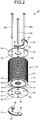
FIG. 2 is a disassembled perspective diagram of the rotor of the electric motor for the compressor according to the embodiment. -
FIG. 3 is a cross-sectional diagram of a balance weight according to the embodiment. -
FIG. 4 is a plan view of the balance weight according to the embodiment. -
FIG. 5 is a disassembled cross-sectional diagram of the balance weight according to the embodiment. -
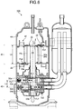
FIG. 6 is a vertical cross-sectional diagram of a compressor for using the rotor of the electric motor for the compressor according to the embodiment. - A case of a six-pole rotor is described in detail below with reference to the drawings as an example of an embodiment of a rotor of an electric motor for a compressor according to the present invention. The present invention is not limited to the embodiment.
- As illustrated in
FIGS. 1 and2 , arotor 10 of an electric motor for a compressor according to the present invention is a rotor for an electric motor for a compressor. Therotor 10 includes a columnar rotor laminatedsteel plate 12 having ashaft hole 30 and apermanent magnet 14. Thepermanent magnet 14 is provided in the rotor laminatedsteel plate 12 and has an N pole and an S pole alternately arranged to configure six poles in a circumferential direction around the rotation axis Z (rotor 10 according to the embodiment is a six-pole rotor). - Also, the
rotor 10 includes disk-shapedrotor end plates steel plate 12 and restrict the movement of thepermanent magnet 14 in an axis direction and arc-shaped plate-like balance weights rotor end plates balance weights balance weights - Three axis direction through-
holes 24, which are arranged with equal intervals in the circumferential direction (120° interval in circumferential direction), are provided in the rotor laminatedsteel plate 12 and therotor end plates hole 24 is provided at a position as avoiding thepermanent magnet 14. Also, it is preferable that the number of axis direction through-holes 24 be three. As illustrated inFIG. 2 , five axis direction through-holes 24 may be arranged. - The rotor laminated
steel plate 12 and therotor end plates rivets holes 24. - One
balance weight 20 is formed of a laminated metal plate in which a plurality of thin metal plates is laminated and fixed to the onerotor end plate 16 with tworivets balance weight 20 formed of the laminated metal plate may be integrated by caulking. However, it is not necessary for thebalance weight 20 to be integrated since thebalance weight 20 is positioned and fixed with the tworivets - As illustrated in
FIGS. 3 and 4 , theother balance weight 22 is formed of a laminated metal plate in whichthin metal plates balance weight 22 is integrated by being caulked at two positions on the end sides.Projections 28 are formed at the two positions on the end sides by the caulking. As illustrated inFIG. 5 , a dimensional relation between an outer diameter D1 of theprojection 28a of thethin metal plate 22a formed by the caulking and an inner diameter D2 of arecess 28b of thethin metal plate 22b formed by inserting theprojection 28a is D1 = D2. The plurality ofthin metal plates projection 28a into therecess 28b. The numbers of laminatedthin metal plates balance weights compression mechanism 40 to be described below. Also, it is preferable that the materials of thebalance weights electric motor 42 to be described below. - Also, the
recesses 32 are formed at two positions on the otherrotor end plate 18 opposed to theprojections 28. Here, therecess 32 may be a through-hole for passing through therotor end plate 18 and may be formed by press molding and the like. It is preferable that the dimensional relation between the outer diameter D3 of theprojection 28 of thethin metal plate 22b and the inner diameter D4 of therecess 32 of therotor end plate 18 be D3 < D4 so that theprojection 28 is easily engaged with therecess 32. - The
other balance weight 22 is fixed to the otherrotor end plate 18 with the remainingsingle rivet 26c and is positioned relative to the otherrotor end plate 18 by engaging theprojection 28 with therecess 32. - In this way, the
projection 28 is formed on theother balance weight 22 by the caulking, and therecess 32 is provided in therotor end plate 18, and then, theprojection 28 is engaged with therecess 32. Accordingly, theother balance weight 22 can be positioned relative to therotor end plate 18, and thebalance weight 22 does not rotate around therivet 26c. Therefore, when thebalance weight 22 is fixed to therotor 10 with thesingle rivet 26c, thebalance weight 22 can be stably positioned to therotor 10 without using a jig for positioning and the like. In addition, thebalance weight 22 is prevented from rotating around therivet 26c during the rotation drive of the rotor by the positioning by the engagement of theprojection 28 with therecess 32. - Next, a case where the
rotor 10 of the electric motor for the compressor according to the present invention is applied to a two-cylinder rotary compressor is described with reference toFIG. 6 . - As illustrated in
FIG. 6 , a two-cylinder rotary compressor 100 includes thecompression mechanism 40 for generating compressed fluid and theelectric motor 42 for driving the compression mechanism 40 (electric motor 42 is six-pole electric motor). Theelectric motor 42 includes astator 46 fixed in ahermetic casing 44 and therotor 10 according to the present invention. Ashaft 48 extending downward to thecompression mechanism 40 is fixed to theshaft hole 30 of therotor 10.Eccentric cranks compression mechanism 40 are provided on the lower side of theshaft 48. - The
compression mechanism 40 includes twocylinders cylinders pistons - When the
shaft 48 of therotor 10 is rotated by driving theelectric motor 42, centrifugal forces Fc1 and Fc2 respectively act on theeccentric cranks pistons - On the other hand, centrifugal forces Fb1 and Fb2 respectively act on the
balance weights rotor 10 of theelectric motor 42. - Here, to ensure the balance of the entire compressor, it is preferable to previously set the positions and masses of the two
balance weights 

- Here, Lc is a distance between working points of the centrifugal forces Fc1 and Fc2 in the axis direction.
- A distance between working points of the centrifugal forces Fp1 and Fp2 in the axis direction is also referred to as Lc.
- Lb is a distance between working points of the centrifugal forces Fb1 and Fb2 in the axis direction.
- As described above, according to the present invention, the
rotor 10 of theelectric motor 42 for a compressor includes the rotor laminatedsteel plate 12, thepermanent magnet 14 which is provided in the rotor laminatedsteel plate 12 and is arranged to form a plurality of magnetic poles in the circumferential direction around the rotation axis, therotor end plates steel plate 12 and restrict the movement of thepermanent magnet 14 in the axis direction, and thebalance weights rotor end plates holes 24 arranged at equal intervals in the circumferential direction are provided in the rotor laminatedsteel plate 12 and therotor end plates steel plate 12 and therotor end plates rivets holes 24. Thebalance weight 20 formed of the one laminated metal plate is fixed to the onerotor end plate 16 with the tworivets rivets balance weight 22 formed of the other of thethin metal plates projection 28 formed thereon and fixed to therotor end plate 18 with the remainingsingle rivet 26c. Theprojection 28 is engaged with therecess 32 or the through-hole provided in the otherrotor end plate 18 so that the balance weight is positioned to the otherrotor end plate 18. - Therefore, when the
balance weight 22 is fixed to therotor 10 with thesingle rivet 26c, thebalance weight 22 can be stably positioned to therotor 10 without using a jig for positioning and the like. In addition, thethin metal plates balance weight 22 is prevented from rotating around therivet 26c during the rotation drive of therotor 10 by the positioning by the engagement of theprojection 28 of thebalance weight 22 formed by the caulking with therecess 32 or the through-hole provided in therotor end plate 18. -
- 10 ROTOR (ROTOR OF ELECTRIC MOTOR FOR COMPRESSOR)
- 12 ROTOR LAMINATED STEEL PLATE
- 14 PERMANENT MAGNET
- 16, 18 ROTOR END PLATE
- 20 BALANCE WEIGHT (ONE BALANCE WEIGHT)
- 22 BALANCE WEIGHT (THE OTHER BALANCE WEIGHT)
- 22a, 22b THIN METAL PLATE
- 24 AXIS DIRECTION THROUGH-HOLE
- 26a, 26b, 26c RIVET
- 28 PROJECTION
- 30 SHAFT HOLE
- 32 RECESS
- 40 COMPRESSION MECHANISM
- 42 ELECTRIC MOTOR
- 44 HERMETIC CASING
- 46 STATOR
- 48 SHAFT
- 50a, 50b ECCENTRIC CRANK
- 52a, 52b CYLINDER
- 54a, 54b PISTON
- 100 COMPRESSOR
Claims (3)
- A rotor of an electric motor for a compressor comprising:a rotor laminated steel plate;a permanent magnet configured to be provided in the rotor laminated steel plate and to be arranged to form a plurality of magnetic poles in a circumferential direction around a rotation axis;rotor end plates configured to be provided on both end surfaces of the rotor laminated steel plate and to restrict movement of the permanent magnet in the axis direction; andbalance weights configured to be formed of laminated metal plates respectively fixed to outer surfaces of the rotor end plates, whereinat least three axis direction through-holes arranged at equal angle intervals in the circumferential direction are provided in the rotor laminated steel plate and the rotor end plates,the rotor laminated steel plate and the rotor end plates are fixed with three rivets for passing through the axis direction through-holes,one of the balance weights formed of one laminated metal plate is fixed to one of the rotor end plates with the two rivets of the three rivets,a projection is formed on the other balance weight formed of the other laminated metal plate which is integrated by caulking, and the other balance weight is fixed to the other rotor end plate with the remaining single rivet, andthe projection is engaged with a recess or a through-hole provided in the other rotor end plate so that the balance weight is positioned to the other rotor end plate.
- The rotor of an electric motor for a compressor according to claim 1, wherein the electric motor is a six-pole electric motor.
- The rotor of an electric motor for a compressor according to claim 1, wherein a material of the balance weight is a nonmagnetic material.
Applications Claiming Priority (2)
| Application Number | Priority Date | Filing Date | Title |
|---|---|---|---|
| JP2014058914A JP5858076B2 (en) | 2014-03-20 | 2014-03-20 | Compressor motor rotor |
| PCT/JP2015/053005 WO2015141307A1 (en) | 2014-03-20 | 2015-02-03 | Rotor for compressor motor |
Publications (2)
| Publication Number | Publication Date |
|---|---|
| EP3121935A1 true EP3121935A1 (en) | 2017-01-25 |
| EP3121935A4 EP3121935A4 (en) | 2017-10-18 |
Family
ID=54144287
Family Applications (1)
| Application Number | Title | Priority Date | Filing Date |
|---|---|---|---|
| EP15765670.3A Ceased EP3121935A4 (en) | 2014-03-20 | 2015-02-03 | Rotor for compressor motor |
Country Status (6)
| Country | Link |
|---|---|
| US (1) | US10141802B2 (en) |
| EP (1) | EP3121935A4 (en) |
| JP (1) | JP5858076B2 (en) |
| CN (1) | CN105993112A (en) |
| AU (1) | AU2015232870B2 (en) |
| WO (1) | WO2015141307A1 (en) |
Families Citing this family (12)
| Publication number | Priority date | Publication date | Assignee | Title |
|---|---|---|---|---|
| JP2017078356A (en) * | 2015-10-20 | 2017-04-27 | 株式会社豊田自動織機 | Centrifugal compressor |
| JP6645210B2 (en) * | 2016-01-26 | 2020-02-14 | 株式会社デンソー | Motor manufacturing method |
| WO2017130565A1 (en) * | 2016-01-26 | 2017-08-03 | 東芝キヤリア株式会社 | Hermetic-type compressor and refrigeration cycle apparatus |
| CN105790463B (en) * | 2016-03-09 | 2018-10-26 | 珠海格力电器股份有限公司 | Motor rotor assembly and air conditioner compressor with same |
| FR3064131B1 (en) * | 2017-03-15 | 2020-03-20 | Valeo Equipements Electriques Moteur | ROTOR OF ROTATING ELECTRIC MACHINE WITH IMPROVED BALANCING FLANGES |
| US11205942B2 (en) * | 2017-03-22 | 2021-12-21 | Mitsubishi Electric Corporation | Motor including a balance weight and compressor provided with the same |
| DE102017123085A1 (en) * | 2017-10-05 | 2019-04-11 | Vorwerk & Co. Interholding Gmbh | External rotor motor |
| DE102019110714B3 (en) * | 2019-04-25 | 2020-07-23 | Dr. Ing. H.C. F. Porsche Aktiengesellschaft | Electric machine rotor and method of manufacturing the same |
| CN117957747A (en) * | 2021-09-06 | 2024-04-30 | 锐马克汽车有限责任公司 | Threaded rotor pressure plate |
| JP7417120B2 (en) * | 2021-10-28 | 2024-01-18 | ダイキン工業株式会社 | Rotors, rotor manufacturing methods, motors, compressors, and refrigeration equipment |
| KR20240040495A (en) * | 2022-09-21 | 2024-03-28 | 한온시스템 주식회사 | Electric compressor |
| CN115347693A (en) * | 2022-09-22 | 2022-11-15 | 珠海凌达压缩机有限公司 | Balance structure of rotor, rotor assembly, motor and compressor |
Family Cites Families (16)
| Publication number | Priority date | Publication date | Assignee | Title |
|---|---|---|---|---|
| JPS6328250A (en) * | 1986-07-21 | 1988-02-05 | Matsushita Refrig Co | Balance weight of electric element of hermetic electric compressor |
| JPH0226370U (en) * | 1988-08-01 | 1990-02-21 | ||
| JPH04185247A (en) * | 1990-11-20 | 1992-07-02 | Seiko Epson Corp | Rotor of electric motor for compressor |
| JPH04237891A (en) | 1991-01-22 | 1992-08-26 | Daikin Ind Ltd | Motor driven compressor |
| JP2720668B2 (en) * | 1991-11-21 | 1998-03-04 | ダイキン工業株式会社 | Permanent magnet type rotor |
| JP3562061B2 (en) | 1995-10-16 | 2004-09-08 | 松下電器産業株式会社 | Hermetic rotary compressor |
| JP4213798B2 (en) * | 1998-10-08 | 2009-01-21 | アイチエレック株式会社 | Hermetic electric compressor |
| EP1330010A4 (en) * | 2000-09-01 | 2007-06-20 | Matsushita Electric Industrial Co Ltd | ELECTRIC MOTOR |
| ES2362171T3 (en) * | 2001-03-30 | 2011-06-29 | Sanyo Electric Co., Ltd. | SYNCHRONOUS INDUCTION MOTOR, MANUFACTURING PROCEDURE AND DRIVE UNIT FOR THE SAME, AND HERMETIC ELECTRIC COMPRESSOR. |
| CN2881019Y (en) * | 2005-05-09 | 2007-03-21 | 支玉柱 | Elastic automatic locking wind hook |
| CN101443982B (en) | 2005-05-12 | 2012-10-31 | Lg电子株式会社 | Rotor of synchronous reluctance motor |
| CN1881753A (en) * | 2005-06-15 | 2006-12-20 | 乐金电子(天津)电器有限公司 | Balance weight structure of compressor rotor |
| JP4687810B2 (en) * | 2009-03-31 | 2011-05-25 | 株式会社富士通ゼネラル | Electric motor rotor |
| JP4539781B1 (en) * | 2009-03-31 | 2010-09-08 | 株式会社富士通ゼネラル | Compressor motor rotor |
| JP5368240B2 (en) * | 2009-09-30 | 2013-12-18 | 株式会社日立産機システム | Cage rotor for electric motor and method for manufacturing the same |
| CN201813251U (en) * | 2010-10-08 | 2011-04-27 | 浙江盾安机械有限公司 | Laminated balance weight connection structure |
-
2014
- 2014-03-20 JP JP2014058914A patent/JP5858076B2/en active Active
-
2015
- 2015-02-03 EP EP15765670.3A patent/EP3121935A4/en not_active Ceased
- 2015-02-03 US US15/121,983 patent/US10141802B2/en active Active
- 2015-02-03 WO PCT/JP2015/053005 patent/WO2015141307A1/en not_active Ceased
- 2015-02-03 AU AU2015232870A patent/AU2015232870B2/en active Active
- 2015-02-03 CN CN201580008659.4A patent/CN105993112A/en active Pending
Also Published As
| Publication number | Publication date |
|---|---|
| WO2015141307A1 (en) | 2015-09-24 |
| US20170077772A1 (en) | 2017-03-16 |
| CN105993112A (en) | 2016-10-05 |
| EP3121935A4 (en) | 2017-10-18 |
| US10141802B2 (en) | 2018-11-27 |
| AU2015232870A1 (en) | 2016-09-01 |
| JP5858076B2 (en) | 2016-02-10 |
| JP2015186302A (en) | 2015-10-22 |
| AU2015232870B2 (en) | 2017-07-27 |
Similar Documents
| Publication | Publication Date | Title |
|---|---|---|
| US10141802B2 (en) | Rotor of electric motor for compressor | |
| EP2416472B1 (en) | Rotor for compressor motors | |
| EP2416013A1 (en) | Electric motor rotor and compressor provided with the same | |
| EP3299622A1 (en) | Electrically driven pump | |
| CN102113196B (en) | Stator, motor and compressor | |
| EP0660491B1 (en) | Motor for electric pumps | |
| US9673679B2 (en) | Driving device | |
| JP2017082684A (en) | Electric compressor | |
| US7102261B2 (en) | Coupling device between a rotor of permanent-magnet synchronous motor and a working part | |
| EP2921706B1 (en) | Scroll compressor | |
| EP2718567B1 (en) | A free piston type torsion drive compressor | |
| CN105992872B (en) | Compressor | |
| KR101462832B1 (en) | Speed increasing or decreasing apparatus using permanent magnets and electric motor having the speed increasing or decreasing apparatus | |
| JPH08182254A (en) | Motor for motor-driven pump | |
| CN109638992B (en) | External rotor motor | |
| CN204316209U (en) | Compressor | |
| JP6520047B2 (en) | Motor and compressor using the same | |
| JP2013211989A (en) | Interior permanent magnet motor and electrical compressor comprising the same | |
| KR20210026884A (en) | Electric motor and compressor having the same | |
| US20050287026A1 (en) | Low density counterweight for eccentric driven pump | |
| JP6515400B2 (en) | Reciprocating displacement type fluid machine of 1 cylinder and 2 cylinders | |
| JPH0747950B2 (en) | Free piston type fluid treatment device |
Legal Events
| Date | Code | Title | Description |
|---|---|---|---|
| PUAI | Public reference made under article 153(3) epc to a published international application that has entered the european phase |
Free format text: ORIGINAL CODE: 0009012 |
|
| STAA | Information on the status of an ep patent application or granted ep patent |
Free format text: STATUS: REQUEST FOR EXAMINATION WAS MADE |
|
| 17P | Request for examination filed |
Effective date: 20160824 |
|
| AK | Designated contracting states |
Kind code of ref document: A1 Designated state(s): AL AT BE BG CH CY CZ DE DK EE ES FI FR GB GR HR HU IE IS IT LI LT LU LV MC MK MT NL NO PL PT RO RS SE SI SK SM TR |
|
| AX | Request for extension of the european patent |
Extension state: BA ME |
|
| DAX | Request for extension of the european patent (deleted) | ||
| A4 | Supplementary search report drawn up and despatched |
Effective date: 20170919 |
|
| RIC1 | Information provided on ipc code assigned before grant |
Ipc: H02K 7/04 20060101ALI20170913BHEP Ipc: H02K 15/16 20060101ALI20170913BHEP Ipc: H02K 1/27 20060101ALI20170913BHEP Ipc: H02K 1/22 20060101AFI20170913BHEP |
|
| STAA | Information on the status of an ep patent application or granted ep patent |
Free format text: STATUS: EXAMINATION IS IN PROGRESS |
|
| 17Q | First examination report despatched |
Effective date: 20180705 |
|
| REG | Reference to a national code |
Ref country code: DE Ref legal event code: R003 |
|
| STAA | Information on the status of an ep patent application or granted ep patent |
Free format text: STATUS: THE APPLICATION HAS BEEN REFUSED |
|
| 18R | Application refused |
Effective date: 20220322 |