EP3358727A1 - Transverse flux reciprocating motor and reciprocating compressor including the same - Google Patents
Transverse flux reciprocating motor and reciprocating compressor including the same Download PDFInfo
- Publication number
- EP3358727A1 EP3358727A1 EP18153908.1A EP18153908A EP3358727A1 EP 3358727 A1 EP3358727 A1 EP 3358727A1 EP 18153908 A EP18153908 A EP 18153908A EP 3358727 A1 EP3358727 A1 EP 3358727A1
- Authority
- EP
- European Patent Office
- Prior art keywords
- stator
- mover
- reciprocating motor
- magnet
- magnet coil
- Prior art date
- Legal status (The legal status is an assumption and is not a legal conclusion. Google has not performed a legal analysis and makes no representation as to the accuracy of the status listed.)
- Granted
Links
- 230000004907 flux Effects 0.000 title claims abstract description 75
- 239000000696 magnetic material Substances 0.000 claims abstract description 9
- 230000006835 compression Effects 0.000 claims description 15
- 238000007906 compression Methods 0.000 claims description 15
- 230000000149 penetrating effect Effects 0.000 claims description 4
- XEEYBQQBJWHFJM-UHFFFAOYSA-N Iron Chemical group [Fe] XEEYBQQBJWHFJM-UHFFFAOYSA-N 0.000 description 20
- 238000004519 manufacturing process Methods 0.000 description 8
- 238000000034 method Methods 0.000 description 8
- 230000008569 process Effects 0.000 description 8
- 238000004804 winding Methods 0.000 description 6
- 239000003507 refrigerant Substances 0.000 description 5
- 230000008859 change Effects 0.000 description 2
- 238000007599 discharging Methods 0.000 description 2
- 230000000694 effects Effects 0.000 description 2
- 239000004020 conductor Substances 0.000 description 1
- 238000007796 conventional method Methods 0.000 description 1
- 230000001419 dependent effect Effects 0.000 description 1
- 230000008014 freezing Effects 0.000 description 1
- 238000007710 freezing Methods 0.000 description 1
- 230000006872 improvement Effects 0.000 description 1
- 230000001050 lubricating effect Effects 0.000 description 1
- 238000004080 punching Methods 0.000 description 1
- 230000008439 repair process Effects 0.000 description 1
- 238000003466 welding Methods 0.000 description 1
Images


Classifications
-
- H—ELECTRICITY
- H02—GENERATION; CONVERSION OR DISTRIBUTION OF ELECTRIC POWER
- H02K—DYNAMO-ELECTRIC MACHINES
- H02K1/00—Details of the magnetic circuit
- H02K1/06—Details of the magnetic circuit characterised by the shape, form or construction
- H02K1/12—Stationary parts of the magnetic circuit
- H02K1/14—Stator cores with salient poles
- H02K1/141—Stator cores with salient poles consisting of C-shaped cores
- H02K1/143—Stator cores with salient poles consisting of C-shaped cores of the horse-shoe type
-
- H—ELECTRICITY
- H02—GENERATION; CONVERSION OR DISTRIBUTION OF ELECTRIC POWER
- H02K—DYNAMO-ELECTRIC MACHINES
- H02K33/00—Motors with reciprocating, oscillating or vibrating magnet, armature or coil system
- H02K33/12—Motors with reciprocating, oscillating or vibrating magnet, armature or coil system with armatures moving in alternate directions by alternate energisation of two coil systems
-
- H—ELECTRICITY
- H02—GENERATION; CONVERSION OR DISTRIBUTION OF ELECTRIC POWER
- H02K—DYNAMO-ELECTRIC MACHINES
- H02K1/00—Details of the magnetic circuit
- H02K1/06—Details of the magnetic circuit characterised by the shape, form or construction
- H02K1/34—Reciprocating, oscillating or vibrating parts of the magnetic circuit
-
- F—MECHANICAL ENGINEERING; LIGHTING; HEATING; WEAPONS; BLASTING
- F04—POSITIVE - DISPLACEMENT MACHINES FOR LIQUIDS; PUMPS FOR LIQUIDS OR ELASTIC FLUIDS
- F04B—POSITIVE-DISPLACEMENT MACHINES FOR LIQUIDS; PUMPS
- F04B35/00—Piston pumps specially adapted for elastic fluids and characterised by the driving means to their working members, or by combination with, or adaptation to, specific driving engines or motors, not otherwise provided for
- F04B35/04—Piston pumps specially adapted for elastic fluids and characterised by the driving means to their working members, or by combination with, or adaptation to, specific driving engines or motors, not otherwise provided for the means being electric
- F04B35/045—Piston pumps specially adapted for elastic fluids and characterised by the driving means to their working members, or by combination with, or adaptation to, specific driving engines or motors, not otherwise provided for the means being electric using solenoids
-
- F—MECHANICAL ENGINEERING; LIGHTING; HEATING; WEAPONS; BLASTING
- F04—POSITIVE - DISPLACEMENT MACHINES FOR LIQUIDS; PUMPS FOR LIQUIDS OR ELASTIC FLUIDS
- F04B—POSITIVE-DISPLACEMENT MACHINES FOR LIQUIDS; PUMPS
- F04B35/00—Piston pumps specially adapted for elastic fluids and characterised by the driving means to their working members, or by combination with, or adaptation to, specific driving engines or motors, not otherwise provided for
- F04B35/06—Mobile combinations
-
- F—MECHANICAL ENGINEERING; LIGHTING; HEATING; WEAPONS; BLASTING
- F04—POSITIVE - DISPLACEMENT MACHINES FOR LIQUIDS; PUMPS FOR LIQUIDS OR ELASTIC FLUIDS
- F04B—POSITIVE-DISPLACEMENT MACHINES FOR LIQUIDS; PUMPS
- F04B39/00—Component parts, details, or accessories, of pumps or pumping systems specially adapted for elastic fluids, not otherwise provided for in, or of interest apart from, groups F04B25/00 - F04B37/00
- F04B39/10—Adaptations or arrangements of distribution members
-
- H—ELECTRICITY
- H01—ELECTRIC ELEMENTS
- H01F—MAGNETS; INDUCTANCES; TRANSFORMERS; SELECTION OF MATERIALS FOR THEIR MAGNETIC PROPERTIES
- H01F3/00—Cores, Yokes, or armatures
-
- H—ELECTRICITY
- H01—ELECTRIC ELEMENTS
- H01F—MAGNETS; INDUCTANCES; TRANSFORMERS; SELECTION OF MATERIALS FOR THEIR MAGNETIC PROPERTIES
- H01F7/00—Magnets
- H01F7/06—Electromagnets; Actuators including electromagnets
- H01F7/08—Electromagnets; Actuators including electromagnets with armatures
-
- H—ELECTRICITY
- H02—GENERATION; CONVERSION OR DISTRIBUTION OF ELECTRIC POWER
- H02K—DYNAMO-ELECTRIC MACHINES
- H02K1/00—Details of the magnetic circuit
- H02K1/06—Details of the magnetic circuit characterised by the shape, form or construction
- H02K1/08—Salient poles
-
- H—ELECTRICITY
- H02—GENERATION; CONVERSION OR DISTRIBUTION OF ELECTRIC POWER
- H02K—DYNAMO-ELECTRIC MACHINES
- H02K1/00—Details of the magnetic circuit
- H02K1/06—Details of the magnetic circuit characterised by the shape, form or construction
- H02K1/12—Stationary parts of the magnetic circuit
- H02K1/14—Stator cores with salient poles
- H02K1/146—Stator cores with salient poles consisting of a generally annular yoke with salient poles
- H02K1/148—Sectional cores
-
- H—ELECTRICITY
- H02—GENERATION; CONVERSION OR DISTRIBUTION OF ELECTRIC POWER
- H02K—DYNAMO-ELECTRIC MACHINES
- H02K3/00—Details of windings
- H02K3/46—Fastening of windings on the stator or rotor structure
- H02K3/52—Fastening salient pole windings or connections thereto
- H02K3/521—Fastening salient pole windings or connections thereto applicable to stators only
-
- H—ELECTRICITY
- H02—GENERATION; CONVERSION OR DISTRIBUTION OF ELECTRIC POWER
- H02K—DYNAMO-ELECTRIC MACHINES
- H02K33/00—Motors with reciprocating, oscillating or vibrating magnet, armature or coil system
-
- H—ELECTRICITY
- H02—GENERATION; CONVERSION OR DISTRIBUTION OF ELECTRIC POWER
- H02K—DYNAMO-ELECTRIC MACHINES
- H02K33/00—Motors with reciprocating, oscillating or vibrating magnet, armature or coil system
- H02K33/16—Motors with reciprocating, oscillating or vibrating magnet, armature or coil system with polarised armatures moving in alternate directions by reversal or energisation of a single coil system
-
- H—ELECTRICITY
- H02—GENERATION; CONVERSION OR DISTRIBUTION OF ELECTRIC POWER
- H02K—DYNAMO-ELECTRIC MACHINES
- H02K7/00—Arrangements for handling mechanical energy structurally associated with dynamo-electric machines, e.g. structural association with mechanical driving motors or auxiliary dynamo-electric machines
- H02K7/14—Structural association with mechanical loads, e.g. with hand-held machine tools or fans
-
- H—ELECTRICITY
- H02—GENERATION; CONVERSION OR DISTRIBUTION OF ELECTRIC POWER
- H02K—DYNAMO-ELECTRIC MACHINES
- H02K2201/00—Specific aspects not provided for in the other groups of this subclass relating to the magnetic circuits
- H02K2201/03—Machines characterised by aspects of the air-gap between rotor and stator
-
- H—ELECTRICITY
- H02—GENERATION; CONVERSION OR DISTRIBUTION OF ELECTRIC POWER
- H02K—DYNAMO-ELECTRIC MACHINES
- H02K2201/00—Specific aspects not provided for in the other groups of this subclass relating to the magnetic circuits
- H02K2201/12—Transversal flux machines
-
- H—ELECTRICITY
- H02—GENERATION; CONVERSION OR DISTRIBUTION OF ELECTRIC POWER
- H02K—DYNAMO-ELECTRIC MACHINES
- H02K2203/00—Specific aspects not provided for in the other groups of this subclass relating to the windings
- H02K2203/12—Machines characterised by the bobbins for supporting the windings
Definitions
- the present invention relates to a transverse flux reciprocating motor and a reciprocating compressor including the same.
- a motor is an apparatus for obtaining rotational force or reciprocating force by converting electric energy into mechanical energy.
- This motor may be categorized into an alternating current motor (AC) and a direct current (DC) motor according to power applied thereto.
- AC alternating current motor
- DC direct current
- the motor includes a stator and a mover (or rotor).
- the mover provided with a magnet rotates or reciprocates according to a direction of flux generated when current flows in a coil provided in the stator.
- the motor may be categorized into a rotary motor and a reciprocating motor according to motion type thereof.
- the mover rotates with respect to the stator by flux generated in the stator by power applied to a magnet coil.
- the mover linearly reciprocates with respect to the stator.
- the reciprocating motor is obtained by modifying flux of a motor, which has a stereoscopic structure, to a flat shape, and is a type of motor having a flat mover, which is arranged on a flat stator to linearly move according to change in a magnetic field of the stator.
- a reciprocating motor for a compressor in which a stator is formed in a cylindrical shape to have an inner stator and an outer stator, a magnet coil that generates an induced magnetic field at any one of the inner stator or the outer stator is wound, and a magnet provided with magnet poles arranged in an axial direction of the stator is provided in a mover to allow the mover to reciprocate in an air gap between the inner stator and the outer stator.
- the reciprocating motor for the compressor is disclosed in Korean Registered Patent No. 10-0492615 (hereinafter, referred to as "prior art 1") and Korean Registered Patent No. 10-0539813 (hereinafter, referred to as “prior art 2").
- an outer stator or inner stator is formed in a cylindrical shape by radially stacking a plurality of iron cores formed of thin plates through punching.
- Prior art 1 discloses a structure in which the plurality of iron cores is radially stacked in both the inner stator and the outer stator.
- Prior art 2 discloses a structure in which the plurality of iron cores is radially stacked in the inner stator and circularly stacked core blocks are radially stacked in the outer stator as improvement of prior art 1.
- the shapes of the core blocks are maintained through a general caulking process. If the areas of the iron cores are small, the shapes of some iron cores may be twisted and modified during the caulking process and thus the sizes of the iron cores cannot be reduced. Therefore, there is a limitation in downsizing the motor.
- the above-described conventional reciprocating motor has a problem in that the mover is supported by the mechanical resonance spring of a compressed coil spring but a specific period is not used as a driving frequency even within a driving frequency of a certain period due to resonance generated by the compressed coil spring.
- the resonance spring of a compressed coil spring As the mechanical resonance spring of a compressed coil spring is installed, there is a restriction in terms of mechanical stress limit and vibration distance in view of properties of the compressed coil spring. For this reason, as the resonance spring should have a certain linear diameter and length, for example, there is a limitation in reducing a horizontal length of the reciprocating motor.
- a spring support member for fixing both ends of the compressed coil spring should be provided in each of the mover and the stator, whereby a problem occurs in that a mechanical structure of the motor is complicated. Also, as a plurality of resonance springs should be pressurized at a high pressure to be installed at both front and rear sides of the mover, a problem occurs in that an assembly process becomes difficult.
- the mover including a magnet is arranged to reciprocate between the outer stator and the inner stator, an air gap is formed at each of an outside and an inside of the mover, whereby an entire air gap is increased, and thus, a problem occurs in that motor efficiency is deteriorated.
- a reciprocating compressor to which the above reciprocating motor is applied, still has the aforementioned problems of the reciprocating motor. For this reason, there is a limitation in downsizing the reciprocating compressor.
- An object of an embodiment of the present invention is to provide a reciprocating motor capable of using all resonant frequencies within a driving frequency.
- Another object of the present invention is to provide a reciprocating motor capable of downsizing a motor in an axial direction.
- Another object of the present invention is to provide a reciprocating motor capable of increasing motor efficiency by reducing the weight of a mover to decrease power consumption.
- Another object of the present invention is to provide a reciprocating motor capable of increasing motor output by increasing only the size of a magnet while maintaining the size of a mover.
- Another object of the present invention is to provide a reciprocating motor capable of minimally maintaining a magnetic air gap by tolerance by reducing the length of a mover.
- Another object of the present invention is to provide a reciprocating motor capable of maximizing rigidity of a motor spring by a magnetic air gap.
- Another object of the present invention is to provide a reciprocating motor capable of reducing manufacturing costs by easily manufacturing a stator and a mover.
- Another object of the present invention is to provide a reciprocating motor capable of easily stacking blocks as compared to radial stacking and advantageously maintaining a stacked state by stacking the blocks configuring a stator or a mover in an axial direction in a surface contact state.
- Another object of the present invention is to provide a reciprocating motor capable of improving workability by winding a magnet coil on a bobbin and then inserting an outer stator into a cavity of the bobbin.
- Another object of the present invention is to provide a small-sized lightweight reciprocating compressor by downsizing the reciprocating motor.
- a transverse flux reciprocating motor includes a stator having an inner stator and an outer stator located outside and spaced apart from the inner stator in a radial direction, at least one magnet coil wound on the stator, at least one magnet coupled to an outer circumferential surface of the inner stator or an inner circumferential surface of the outer stator and having different magnetic poles arranged in an orthogonal direction of flux generated by the magnet coil, and a mover inserted into a cavity formed between the inner stator and the outer stator, formed of a magnetic material and reciprocating with respect to the stator. Therefore, it is possible to reduce power consumption to increase motor efficiency, by reducing the weight of the mover. In addition, a movable core is exposed to an air gap and thus a magnetic air gap among the movable core, the magnet and the stator can be minimally maintained.
- stator and/or the mover may be formed by stacking a plurality of core blocks in a reciprocating direction of the mover. Therefore, since the blocks configuring the stator or the mover are stacked in the axial direction while surface-contacting each other, stacking is easy as compared to radial stacking and a stacked state is advantageously maintained.
- the outer stator may include a yoke part forming a magnetic path and teeth parts extending from the yoke part in a radial direction to surround the mover, the magnet coil may be wound on and coupled to the teeth parts.
- even number of teeth parts may be formed at a predetermined interval in a circumferential direction of the stator, and the magnet coil coupled to each of the teeth parts may generate flux in a direction opposite to a direction of flux generated by a neighboring magnet coil.
- the number of magnets may be equal to that of the magnet coils and the magnets may be arranged to have magnetic poles opposite to those of neighboring magnets.
- the outer stator may include a yoke part forming a magnetic path and teeth parts extending from the yoke part to surround the mover, and the magnet coil may be wound on the yoke part.
- the yoke part and the teeth parts may be separated, the magnet coil may form a cavity, and the yoke part may be inserted into the cavity of the magnet coil and then connected to the teeth parts or the teeth parts may be inserted into the cavity of the magnet coil and then connected to the yoke part. Therefore, after the magnet coil is wound on the bobbin, the outer stator is inserted into the cavity of the bobbin, thereby improving workability.
- the outer stator may be formed by stacking a plurality of stator core blocks having the yoke part and the teeth parts, and a fastening hole may be formed in the yoke part or the teeth parts and the plurality of stator core blocks may be fastened by a fastening member penetrating through the fastening hole.
- stator may include the yoke part formed such that the magnet coils are provided at both sides of the teeth parts.
- stator may include the yoke part formed such that the magnet coil is provided at one side of the teeth parts.
- the yoke part coupled with the magnet coil may be divided into a plurality of yoke parts and the magnet coil forms a cavity, and at least one of the plurality of yoke parts may be inserted into the cavity of the magnet coil. Therefore, after the magnet coil is wound on the bobbin, the outer stator is inserted into the cavity of the bobbin, thereby improving workability.
- a plurality of magnets may be coupled in a circumferential direction of an outer circumferential surface of the inner stator or an outer circumferential surface of the outer stator and may be arranged to have magnetic poles different from those of neighboring magnets.
- the magnet coil may be wound on a bobbin having a cavity.
- the plurality of divided yoke parts may be inserted into the cavity of the magnet coil and then connected to each other.
- a reciprocating compressor includes a case having an internal space, a reciprocating motor provided in the internal space of the case and having a reciprocating mover, a piston coupled to the mover of the reciprocating motor and reciprocating along with the mover, a cylinder having the piston inserted into and forming a compression space, a suction valve opening and closing a suction side of the compression space, and a discharge valve opening and closing a discharge side of the compression space.
- the reciprocating motor includes the above-described transverse flux reciprocating motor. Therefore, since a small-sized lightweight reciprocating motor is provided, the size and weight of the reciprocating compressor can be reduced.
- FIG. 1 is a schematic perspective view showing a transverse flux reciprocating motor according to an embodiment of the present invention.
- FIG. 2 is a perspective view showing a part of the transverse flux reciprocating motor of FIG. 1 .
- the transverse flux reciprocating motor (hereinafter, referred to as a reciprocating motor) according to the present embodiment may include a stator 100, magnet coils 210, a magnet 300 and a mover 400.
- the stator 100 may include at least one of an inner stator 110 and an outer stator 120 located outside the inner stator 110 in a radial direction and spaced apart from the inner stator.
- stator 100 may include only the inner stator 110 or the outer stator 120 or include the inner stator 110 and the outer stator 120.
- stator 100 includes the inner stator 110 and the outer stator 120, the range of the present invention is not limited thereto and the stator 100 may include only the inner stator 110 or the outer stator 120.
- stator 100 includes only the inner stator 110
- the mover 400 may be located outside and spaced apart from the stator 100, and the magnet 300 may be attached to the inner circumferential surface of the stator 100.
- stator 100 includes only the outer stator 120
- the mover 400 may be located inside and space apart from the stator 100 and the magnet 300 may be attached to the inner circumferential surface of the stator 100.
- stator 100 includes the inner stator 110 and the outer stator 120
- the outer diameter of the inner stator 110 is less than the inner diameter of the outer stator 120 and an air gap 130 is formed between the inner stator 110 and the outer stator 120.
- the inner stator 110 and the outer stator 120 configuring the stator 100 may be made of a magnetic material or a conductive material.
- the inner stator 100 forms a cavity 111 and the cavity 111 is used as a space where a piston, etc. will be provided.
- inner stator 110 and the outer stator 120 may be integrally formed and, in some cases, may be configured by stacking a plurality of blocks.
- FIGS. 3 to 4 are cross-sectional views taken along lines IV-IV and IV'-IV' of FIG. 1 .
- the inner stator 110 and the outer stator 120 may be configured by stacking inner core blocks 110a and outer core blocks 120a in an axial direction (a reciprocating direction of the mover).
- the inner stator 110 and the outer stator 120 are configured by stacking the inner core blocks 110a and the outer core blocks 120a in the axial direction, the blocks may be easily stacked as compared to the conventional method of radially stacking the blocks. In addition, the stacked state is advantageously maintained as compared to radial stacking.
- the magnet coil 210 is wound on the outer stator 120.
- the magnet coil 210 may be directly wound on the outer stator 120.
- the magnet coil 210 may be first wounded and coupled to the outer stator 120 in a state of being wound.
- the magnet coil 210 may be wound on a bobbin through a separate winding device and then the magnet coil 210 may be coupled to the outer stator 120 by inserting the outer stator 120 into the cavity of the bobbin.
- the magnet 300 is coupled to the outer circumferential surface of the inner stator 110 or the inner circumferential surface of the outer stator 120. At this time, the magnet is arranged to have different magnet poles in an orthogonal direction of flux generated by the magnet coil 210 of the magnet 300.
- the magnet 300 may be arranged to have different magnet poles in the axial direction (the reciprocating direction of the mover).
- the magnet 300 may be provided such that the cross section thereof has a circular or arc shape, thereby surface-contacting the outer circumferential surface of the inner stator 110 or the inner circumferential surface of the outer stator 120, which is a curved surface.
- the magnet 300 has a cylindrical shape or an arc-shaped cross section when viewed in the axial direction or a plurality of magnets may be spaced apart from each other on the outer circumferential surface of the inner stator 110 or the inner circumferential surface of the outer stator 120 in a circumferential direction.
- the magnet 300 may be a 2-pole magnet having an N pole and an S pole having the same length.
- the magnet 300 is exposed to the air gap 130.
- the magnet 300 may be fixed to the outer stator 120. As another example, the magnet 300 may be fixed to the inner stator 110. As another example, the magnet 300 may be fixed to the inner stator 110 and the outer stator 120.
- the plurality of magnets 300 is formed on the outer circumferential surface of the inner stator 110 or the inner circumferential surface of the outer stator 120 in the circumferential direction. At this time, an air gap is formed between the magnets 300.
- a magnet 300 is arranged to have a magnet pole different from that of a neighboring magnet 300.
- a first magnet 310 located at the upper side of the figure may have a magnet pole different from those of a third magnet 330 located at the left side of the figure and a fourth magnet 340 located at the right side of the figure but have the same magnet pole as a second magnet 320 located at the lower side of FIG. 1 .
- an upper magnet and a lower magnet may have different magnet poles.
- the mover 400 is inserted into the air gap 130 formed between the inner stator 110 and the outer stator 120, is made of a magnetic material and reciprocates with respect to the stator 100.
- At least a part of an axial cross section of the mover 400 may have an arc shape.
- the mover 400 is formed as a single body and may have a cylindrical shape such that the mover 400 is inserted into the cylindrical gap 130 formed between the inner stator 110 and the outer stator 120.
- a plurality of movers 400 may be formed to have an arc-shaped cross section when viewed in the axial direction and may be spaced apart from each other in a circumferential direction.
- a gap may be formed between the movers 400 and joints made of a non-magnetic material may be formed in the gap. By the joints, the plurality of movers 400 may be coupled as a single body.
- the mover 400 may be connected to a piston through a connector.
- the connector 70 may have a cylindrical shape to be connected to the inner circumferential surface or outer circumferential surface of the mover 400 having the cylindrical shape.
- the plurality of movers 400 each having an arc-shaped cross section may be spaced apart from each other along the circumference of the connector 70.
- the size of the mover 400 is less than that of the air gap 130.
- the diameters of the inner circumferential surface of the mover 400 may be greater than that of the outer circumferential surface of the inner stator 110 and the diameter of the outer circumferential surface of the mover 400 may be less than that of the inner circumferential surface of the outer stator 120.
- the mover 400 may be configured as a single body and, in some cases, may be configured by stacking a plurality of blocks.
- the plurality of mover core blocks may be stacked in the reciprocating direction of the mover 400.
- the outer stator 120 may include a yoke part 121 forming a magnetic path and a teeth parts 122 extending from the yoke part 121 in a radial direction to surround the mover 400.
- the magnet coil 210 may be wound on and coupled to the teeth part 122.
- the yoke part 121 is formed in an annular shape and the teeth parts 122, on which the magnet coils are wound, may be extended on the inner circumferential surface of the yoke part 121 in the radial direction.
- a space 124 may be formed between the teeth parts 122 and the magnet coil 210 may be wound therein. Accordingly, the teeth parts 122 and the space 124 may be alternately formed in the circumferential direction.
- Even number of teeth parts 122 may be formed at a predetermined gap in the circumferential direction of the stator 100, and the magnet coil 210 coupled to each teeth part 122 may form flux in an opposite direction of flux generated by a neighboring magnet coil 210.
- the magnet coils 210 may be alternately wound in opposite directions along the circumferential direction.
- the flux direction of the teeth part 122 may be opposite to that of a neighboring teeth part in the circumferential direction.
- a first magnet coil 211 located at the upper side of the figure is wound in a direction opposite to the winding direction of a third magnet coil 213 located at the left side of the figure and a fourth magnet coil 214 located at the right side of the figure and is wound in the same direction as a second magnet coils 212 located at the lower side of the figure.
- the number of magnets 300 is equal to the number of magnet coils 210 and the magnets 300 may be arranged to have a magnetic pole opposite to that of a neighboring magnet 300.
- FIG. 5 is a front view showing the transverse flux reciprocating motor of FIG. 1 .
- the teeth parts 122 may include a first teeth part 122a extending from the internal upper end of the yoke part 121 downward, a second teeth part 122b extending from the internal lower end of the yoke part 121 upward, a third teeth part 122c extending from the left to the right of the yoke part 121 and a fourth teeth part 122d extending from the right to the left of the yoke part 121.
- stator pole part 125 having the magnet 300 fixed on the inner circumferential surface thereof may be extend on the inner end of each teeth part 122 in the circumferential direction.
- the circumferential length of the stator pile 125 may be equal to that of the magnet 300.
- stator pole 125 may include a first stator pole 125a formed on the inner end of the first teeth part 122a, a second stator pole 125b formed on the inner end of the second teeth part 122b, a third stator pole 125c formed on the inner end of the third teeth part 122c and a fourth stator pole 125d formed on the inner end of the fourth teeth part 122d.
- the magnets 310, 320, 330 and 340 may be fixed to the stator poles 125a, 125b, 125c and 125d, respectively.
- teeth parts that is, at least two teeth parts are formed and even number of magnet coils 210 wound on the teeth parts 122 are provided.
- a fastening hole 123 may be formed in each outer core block 120a and the plurality of outer core blocks 120a may be integrally coupled by a fastening member (not shown) penetrating through the fastening hole 123.
- the fastening hole 123 may be formed in the yoke part 121 and/or the teeth parts 122.
- a fastening hole 113 may be formed in each inner core block 110a and the plurality of inner core blocks 110a may be integrally coupled.
- a fastening hole may be formed in each mover core block (not shown) and the plurality of mover core blocks (not shown) may be integrally coupled by the fastening member (not shown) penetrating through the fastening hole (not shown).
- the yoke part 121 and the teeth parts 122 may be separated and a cavity 201 may be formed by the magnet coil 210, such that the yoke part 121 is inserted into the cavity 201 of the magnet coil 210 and then connected to the teeth parts 122 or the teeth parts 122 are inserted into the cavity 201 of the magnet coil 210 and then connected to the yoke part 121.
- the yoke part 121 and the teeth parts 122 may be separated and then integrally connected.
- the yoke part 121 may be separated into a plurality of yoke parts and then integrally connected.
- the teeth part 122 may be separated into a plurality of teeth parts and then integrally connected.
- the plurality of yoke parts 121 and/or teeth parts 122 separated in various forms may be inserted into the cavity 201 of the magnet coil 210 and then connected to each other.
- the separated yoke parts 121 or the teeth parts 122 may be bonded into one body through welding.
- the magnet coil 210 is not wound on the yoke parts 121 or the teeth parts 122 using a winding device (not shown) and a plurality of magnet coils 210 may be manufactured in an annular shape, the yoke parts 121 or the teeth parts 122 may be inserted into the cavities 201 of the magnet coils 210, and the magnet coils 210 may be coupled to the outer stator 120.
- the width t2 of the teeth part 122 may be greater than the width t1 of the yoke part 121.
- the area of the magnetic path of the teeth part 122 may be ensured to improve performance of the motor.
- the reciprocating motor according to the embodiment of the present invention including the above-described configuration reciprocates by reciprocating centering force generated among the stator 100 including the magnet coil 210, the magnet 300 and the mover 400.
- the reciprocating centering force means force moving to low magnetic energy (low magnetic position energy, low magnetic resistance) when the mover 400 moves within a magnetic field. This force forms a magnetic spring.
- the mover 400 when the mover 400 reciprocates by magnetic force generated by the magnet coil 210 and the magnet 300, the mover 400 accumulates force to be restored in the center direction by the magnetic spring and the mover 400 continuously reciprocates while resonating due to force accumulated in the magnetic spring.
- FIGS. 6 and 7 are schematic views taken along line V-V of FIG. 5 in order to explain operation of the reciprocating motor according to the present embodiment.
- a magnetic resonance spring is formed among the mover 400, the stator 100 and the magnet 300, thereby causing resonant motion of the mover 400.
- both fluxes are combined in the teeth parts 122a and 122c to flow in the same direction, such that the teeth parts 122a and 122c have different magnet poles.
- the mover 400 which is a magnetic material, moves in the left direction (see arrow M1) of the figure in which fluxes generated by the magnet coils 211 and 213 and fluxes generated by the magnets 310 and 330 increase.
- the mover 400 moves in the right direction of the figure (see arrow M2) .
- the mover 400 passes the center of the magnets 310 and 330 to further move in the right direction of the figure, by inertial force and magnetic force.
- the teeth parts 122a and 122c have magnet poles opposite to previous magnet poles, and the mover 400 moves in the center directions of the magnets 310 and 330 by the accumulated reciprocating centering force F2 and magnetic force generated by fluxes of the first magnet coil 211, the third magnet coil 213 and the magnets 310 and 330.
- the mover 400 passes the center of the magnets 310 and 330 to further move in the left direction of the figure, by inertial force and magnetic force, and reciprocating centering force F1 to be restored in the center direction of the magnet 300 having low magnetic energy, that is, the right direction of the figure, is accumulated among the mover 400, the stator 100 and the magnets 310 and 330. In this manner, the mover 400 continuously and repeatedly reciprocates in the right and left directions of the figure, as if a mechanical resonant spring is provided.
- FIG. 8 is a perspective view showing another embodiment to the reciprocating motor according to the present invention.
- the outer stator 120 may have the yoke part 121 formed such that the magnet coils 210 are disposed on both sides of the teeth parts 122.
- the outer stator 120 has the yoke part 121 formed in a rectangular ring shape, and the teeth parts 122 formed at both opposite inner side surfaces of the yoke part 121 to protrude toward the center thereof. At this time, an air gap is formed between the opposite teeth part 122.
- the yoke part 121 may include transverse yoke parts 121a extending from both side surfaces of the teeth parts 122 and longitudinal yoke parts 121b extending from the ends of the transverse yoke parts 121a inward in an orthogonal direction.
- teeth parts 122 are spaced apart from each other to form slots 121c with the longitudinal yoke parts 121b and magnet attachment surfaces, to which the magnet 300 is attached, may be provided in the teeth parts 122 in an arch shape.
- the longitudinal yoke parts 121b may be formed as a single body.
- the magnet coils 210 may be wound on the longitudinal yoke parts 121b.
- FIG. 9 is an exploded perspective view of the reciprocating motor of FIG. 8 .
- air gaps may be formed in the centers of the longitudinal yoke parts 121b such that both sides of the longitudinal yoke parts are separated. That is, the air gaps are formed between the yoke parts 121 as if the air gaps are formed between the opposite teeth parts 122.
- the outer stator 120 may be divided into two outer stators.
- the outer stator 120 is divided into two outer stators, the ends of the longitudinal yoke parts 121b facing each other are inserted into the cavities 201 of the magnet coils 210. Accordingly, flux may form a closed loop.
- the outer stator 120 is divided as described above, since the ends of the longitudinal yoke parts 121b are only inserted into the cavities 201 after winding the magnet coils 210 on a bobbin 220 having a cavity, the magnet coils 210 do not need to be wound on the longitudinal yoke parts 121b, thereby improving workability.
- FIG. 10 is a schematic view taken along line VI-VI of FIG. 8 in order to explain operation of the reciprocating motor according to the present embodiment.
- the magnet coils 215 and 216 coupled to both yoke parts 121 are wound in opposite directions.
- magnets 350 and 360 are respectively attached to the teeth parts 122 facing each other, the magnets 350 and 360 form magnetic poles opposite to each other, and a gap is formed between the magnets 350 and 360.
- the mover 400 which is the magnetic material, moves in the left direction (see arrow M1) of the figure in which the fluxes of the magnet coils 215 and 216 and the fluxes of the magnets 310 and 330 increase.
- the mover 400 moves in the right direction of the figure.
- the mover 400 passes the center of the magnets 350 and 360 to further move in the right direction of the figure, by inertial force and magnetic force.
- the mover 400 continuously and repeatedly reciprocates in the right and left directions of the figure, as if a mechanical resonant spring is provided.
- FIG. 11 is a perspective view showing another embodiment of the reciprocating motor according to the present invention
- FIG. 12 is a front view showing the transverse flux reciprocating motor of FIG. 11 .
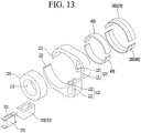
- the outer stator 120 may include the yoke part 121 formed such that the magnet coil 210 is disposed at one side of the teeth part 122.
- the yoke part 121 may include a transverse yoke part 121a extending from one side of the teeth part 122 and longitudinal yoke parts 121b extending from the end of the transverse yoke part 121a in an orthogonal direction.
- teeth parts 122 are spaced apart from the longitudinal yoke parts 121b to form a slot 121c therewith, and a magnet attachment surface, to which the magnet 300 is attached, may be provided in the teeth part 122 in an arch shape.
- the longitudinal yoke parts 121b may be formed as a single body.
- the magnet coil 210 may be wound on the longitudinal yoke parts 121b.
- FIG. 13 is an exploded perspective view of the transverse flux reciprocating motor of FIG. 11 .
- air gaps may be formed in the centers of the longitudinal yoke parts 121b such that both sides of the longitudinal yoke parts are separated. That is, air gaps are formed between the yoke parts 121, as if the air gaps are formed between the teeth parts 122 facing each other.
- the outer stator 120 may be divided into two outer stators.
- the outer stator 120 is divided into two outer stators, the ends of the longitudinal yoke parts 121b facing each other are inserted into cavity 201 of the magnet coil 210. Accordingly, flux may form a closed loop.
- the outer stator 120 is divided as described above, since the ends of the longitudinal yoke parts 121b are only inserted into the cavity 201 after winding the magnet coil 210 on a bobbin 220 having the cavity, the magnet coil 210 does not need to be wound on the longitudinal yoke parts 121b, thereby improving workability.
- FIG. 14 is a schematic view taken along line VII-VII of FIG. 11 in order to explain operation of the reciprocating motor according to the present embodiment.
- magnets 370 and 380 are respectively attached to the teeth parts 122 facing each other and form magnetic poles opposite to each other.
- both teeth parts 122 form different magnetic poles.
- the mover 400 which is the magnetic material, moves in the left direction (see arrow M1) of the figure in which the flux of the magnet coil 217 and the fluxes of the magnets 370 and 380 increase.
- reciprocating centering force (see arrow F1) to be restored in the right direction of the figure having low magnetic energy (that is, low magnetic position energy or low magnetic resistance) is accumulated among the mover 400, the stator 100 and the magnets 370 and 380.
- the mover 400 moves in the right direction of the figure.
- the mover 400 passes the center of the magnets 370 and 280 to further move in the right direction of the figure, by inertial force and magnetic force.
- the mover 400 continuously and repeatedly reciprocates in the right and left directions of the figure, as if a mechanical resonant spring is provided.
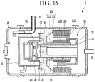
- FIG. 15 is a longitudinal cross-sectional view of an embodiment of a reciprocating compressor, to which the reciprocating motor according to the present embodiment is applied.
- the reciprocating compressor 1 may include a case 10 having an internal space, a reciprocating motor 20 provided in the internal space of the case 10 and having a reciprocating mover 400, a piston 30 coupled to the mover 400 of the reciprocating motor 20 to reciprocate with the mover, a cylinder 40 having the piston 30 inserted thereto and forming a compression space 42, a suction valve 31 opening and closing a suction side of the compression space 42 and a discharging valve 41 opening and closing a discharging side of the compression space 42.
- a suction pipe 11 is connected to the internal space of the sealed case 10 and a discharge pipe 12 guiding refrigerant compressed in the compression space 42 of the cylinder 40, which will be described below, to a freezing cycle is connected to one side of the suction pipe 11. Therefore, the internal space of the case 10 is filled with the sucked refrigerant to form suction pressure, and refrigerant discharged from the compression space 42 may be discharged to the outside of the case 10 toward a condenser through the discharge pipe 12.
- a frame 50 is formed in the internal space of the case 10 and a reciprocating motor 20 for generating reciprocating force and causing resonant motion of the piston 30, which will be described below, is fixed to one side of the frame 50
- the compression space 42 is provided in the reciprocating motor 20 such that the cylinder 40 inserted into the frame 50 is coupled, and the piston 30, which is reciprocatingly inserted into the cylinder 40 to change the volume of the compression space 42 to compress refrigerant, is coupled to the cylinder 40.
- a suction valve 31 opening and closing the suction flow channel of the piston 30 is coupled to the front end of the piston 30, and a discharge valve 41 opening and closing the compression space 42 of the cylinder 40 is received in a discharge cover 60 and is detachably coupled to the front end of the cylinder 40.
- the discharge cover 60 is provided in the discharge space 61 to be fixed and coupled to the cylinder 40.
- the discharge valve 41 and a valve spring 43 supporting the discharge valve 41 may be received and an inlet of a gas bearing for lubricating a space between the cylinder 40 and the piston 30 may be received, in the discharge space 61 of the discharge cover 60.
- the gas bearing may include a gas passage formed between an inner circumferential surface of the frame 50 and an outer circumferential surface of the cylinder 40 and a plurality of fine gas through-holes passing through an inner circumferential surface of the cylinder 40 from the middle of the gas passage.
- the reciprocating motor 20 has the configuration shown in FIGS. 1 to 14 . Therefore, for the configuration of the reciprocating motor, refer to the above-described reciprocating motor.
- the inner stator 110 and the outer stator 120 are fixed to the frame 50 and the mover 400 is connected to the piston 30. Accordingly, when the mover 400 reciprocates with respect to the stator 100 and the magnet 300, the piston 30 inserted into the cylinder 40 may bidirectionally reciprocate along with the mover 400.
- alternating flux may be formed among the stator 100, the magnet 300 and the mover 400, and the mover 400 and the piston 30 connected thereto continuously reciprocate while moving in a direction in which flux of the magnet coil 310 and flux of the magnet 300 increase.
- the magnetic resonance spring may be formed among the mover 400, the stator 100 and the magnet 300 while the mover 400 reciprocates in the reciprocating motor, thereby causing resonant motion of the mover 400 and the piston 30.
- the piston 30 may compress refrigerant while overcoming gas force generated in the compression space 42.
- the reciprocating compressor according to the present invention has the above-described operation effects according to the reciprocating motors of FIGS. 1 to 14 . Therefore, for the operation effects of the reciprocating compressor, refer to the above-described reciprocating motor.
- the reciprocating compressor of the present embodiment includes a small-sized lightweight reciprocating motor and thus has a small size and lightweight. Accordingly, it is possible to easily mount, maintain and repair the compressor.
Abstract
Description
- The present invention relates to a transverse flux reciprocating motor and a reciprocating compressor including the same.
- A motor is an apparatus for obtaining rotational force or reciprocating force by converting electric energy into mechanical energy. This motor may be categorized into an alternating current motor (AC) and a direct current (DC) motor according to power applied thereto.
- The motor includes a stator and a mover (or rotor). The mover provided with a magnet rotates or reciprocates according to a direction of flux generated when current flows in a coil provided in the stator.
- The motor may be categorized into a rotary motor and a reciprocating motor according to motion type thereof. In a case of the rotary motor, the mover rotates with respect to the stator by flux generated in the stator by power applied to a magnet coil. In contrast, in a case of the reciprocating motor, the mover linearly reciprocates with respect to the stator.
- The reciprocating motor is obtained by modifying flux of a motor, which has a stereoscopic structure, to a flat shape, and is a type of motor having a flat mover, which is arranged on a flat stator to linearly move according to change in a magnetic field of the stator.
- Recently, a reciprocating motor for a compressor has been introduced, in which a stator is formed in a cylindrical shape to have an inner stator and an outer stator, a magnet coil that generates an induced magnetic field at any one of the inner stator or the outer stator is wound, and a magnet provided with magnet poles arranged in an axial direction of the stator is provided in a mover to allow the mover to reciprocate in an air gap between the inner stator and the outer stator.
- The reciprocating motor for the compressor is disclosed in Korean Registered Patent No.
10-0492615 prior art 1") and Korean Registered Patent No.10-0539813 - In the
prior art 1 and the prior art 2, an outer stator or inner stator is formed in a cylindrical shape by radially stacking a plurality of iron cores formed of thin plates through punching.Prior art 1 discloses a structure in which the plurality of iron cores is radially stacked in both the inner stator and the outer stator. Prior art 2 discloses a structure in which the plurality of iron cores is radially stacked in the inner stator and circularly stacked core blocks are radially stacked in the outer stator as improvement ofprior art 1. - However, in the above-described conventional reciprocating motor, since several hundreds of iron cores are individually punched and then radially stacked to form the inner stator or the outer stator as described above, it is difficult to punch and radially stack several hundreds of iron cores and to cylindrically fix the iron cores. Therefore, it is difficult to manufacture the inner stator and the outer stator.
- That is, since many iron cores, that is, several hundreds of iron cores, are punched, manufacturing costs increase. In addition, since the iron cores are individually and radially stacked, an assembling process is difficult and an assembling time is excessively increased, thereby increasing manufacturing costs.
- In addition, even when a predetermined number of iron cores is individually stacked to form several core blocks and then the core blocks are radially stacked, since several hundreds of iron cores are punched and the iron cores are individually and radially stacked in the inner stator, the disadvantage of the assembling process of assembling the stator and the disadvantage of manufacturing costs required therefor still remain.
- In addition, in the conventional reciprocating motor, in order to fix and maintain the inner stator and the outer stator in the cylindrical shape, a fixing ring is pressed. However, when the iron cores are individually stacked, it is difficult to stack the iron cores while aligning the positions of fixing grooves provided in the iron cores and to press and fix the fixing ring into the fixing grooves provided in the several hundreds of iron cores.
- In addition, if the plurality of iron cores is combined to form the core blocks, the shapes of the core blocks are maintained through a general caulking process. If the areas of the iron cores are small, the shapes of some iron cores may be twisted and modified during the caulking process and thus the sizes of the iron cores cannot be reduced. Therefore, there is a limitation in downsizing the motor.
- In addition, the above-described conventional reciprocating motor has a problem in that the mover is supported by the mechanical resonance spring of a compressed coil spring but a specific period is not used as a driving frequency even within a driving frequency of a certain period due to resonance generated by the compressed coil spring.
- Further, according to the conventional reciprocating motor, as the mechanical resonance spring of a compressed coil spring is installed, there is a restriction in terms of mechanical stress limit and vibration distance in view of properties of the compressed coil spring. For this reason, as the resonance spring should have a certain linear diameter and length, for example, there is a limitation in reducing a horizontal length of the reciprocating motor.
- Furthermore, according to the conventional reciprocating motor, as the mechanical resonance spring of a compressed coil spring is installed, a spring support member for fixing both ends of the compressed coil spring should be provided in each of the mover and the stator, whereby a problem occurs in that a mechanical structure of the motor is complicated. Also, as a plurality of resonance springs should be pressurized at a high pressure to be installed at both front and rear sides of the mover, a problem occurs in that an assembly process becomes difficult.
- In addition, according to the conventional reciprocating motor, as the mechanical resonance spring of the compressed coil spring is installed, while the mover is eccentrically disposed by side force generated due to the properties of the compressed coil spring, friction loss with the stator increases.
- Additionally, according to the conventional reciprocating motor, as the mover including a magnet is arranged to reciprocate between the outer stator and the inner stator, an air gap is formed at each of an outside and an inside of the mover, whereby an entire air gap is increased, and thus, a problem occurs in that motor efficiency is deteriorated.
- Also, according to the conventional reciprocating motor, since the thickness of a magnet frame supporting a magnet is large and thus the total weight of the mover is increased, whereby power consumption is increased and an air gap between the outer stator and the inner stator is further increased, whereby a problem occurs in that motor efficiency is more deteriorated.
- Finally, a reciprocating compressor, to which the above reciprocating motor is applied, still has the aforementioned problems of the reciprocating motor. For this reason, there is a limitation in downsizing the reciprocating compressor.
- An object of an embodiment of the present invention is to provide a reciprocating motor capable of using all resonant frequencies within a driving frequency.
- Another object of the present invention is to provide a reciprocating motor capable of downsizing a motor in an axial direction.
- Another object of the present invention is to provide a reciprocating motor capable of increasing motor efficiency by reducing the weight of a mover to decrease power consumption.
- Another object of the present invention is to provide a reciprocating motor capable of increasing motor output by increasing only the size of a magnet while maintaining the size of a mover.
- Another object of the present invention is to provide a reciprocating motor capable of minimally maintaining a magnetic air gap by tolerance by reducing the length of a mover.
- Another object of the present invention is to provide a reciprocating motor capable of maximizing rigidity of a motor spring by a magnetic air gap.
- Another object of the present invention is to provide a reciprocating motor capable of reducing manufacturing costs by easily manufacturing a stator and a mover.
- Another object of the present invention is to provide a reciprocating motor capable of easily stacking blocks as compared to radial stacking and advantageously maintaining a stacked state by stacking the blocks configuring a stator or a mover in an axial direction in a surface contact state.
- Another object of the present invention is to provide a reciprocating motor capable of improving workability by winding a magnet coil on a bobbin and then inserting an outer stator into a cavity of the bobbin.
- Another object of the present invention is to provide a small-sized lightweight reciprocating compressor by downsizing the reciprocating motor.
- The present invention is defined by
independent claim 1; the dependent claims describe embodiments of the invention. A transverse flux reciprocating motor according to the present invention includes a stator having an inner stator and an outer stator located outside and spaced apart from the inner stator in a radial direction, at least one magnet coil wound on the stator, at least one magnet coupled to an outer circumferential surface of the inner stator or an inner circumferential surface of the outer stator and having different magnetic poles arranged in an orthogonal direction of flux generated by the magnet coil, and a mover inserted into a cavity formed between the inner stator and the outer stator, formed of a magnetic material and reciprocating with respect to the stator. Therefore, it is possible to reduce power consumption to increase motor efficiency, by reducing the weight of the mover. In addition, a movable core is exposed to an air gap and thus a magnetic air gap among the movable core, the magnet and the stator can be minimally maintained. - In addition, the stator and/or the mover may be formed by stacking a plurality of core blocks in a reciprocating direction of the mover. Therefore, since the blocks configuring the stator or the mover are stacked in the axial direction while surface-contacting each other, stacking is easy as compared to radial stacking and a stacked state is advantageously maintained.
- In addition, the outer stator may include a yoke part forming a magnetic path and teeth parts extending from the yoke part in a radial direction to surround the mover, the magnet coil may be wound on and coupled to the teeth parts.
- In addition, even number of teeth parts may be formed at a predetermined interval in a circumferential direction of the stator, and the magnet coil coupled to each of the teeth parts may generate flux in a direction opposite to a direction of flux generated by a neighboring magnet coil.
- In addition, the number of magnets may be equal to that of the magnet coils and the magnets may be arranged to have magnetic poles opposite to those of neighboring magnets.
- In addition, the outer stator may include a yoke part forming a magnetic path and teeth parts extending from the yoke part to surround the mover, and the magnet coil may be wound on the yoke part.
- In addition, the yoke part and the teeth parts may be separated, the magnet coil may form a cavity, and the yoke part may be inserted into the cavity of the magnet coil and then connected to the teeth parts or the teeth parts may be inserted into the cavity of the magnet coil and then connected to the yoke part. Therefore, after the magnet coil is wound on the bobbin, the outer stator is inserted into the cavity of the bobbin, thereby improving workability.
- In addition, the outer stator may be formed by stacking a plurality of stator core blocks having the yoke part and the teeth parts, and a fastening hole may be formed in the yoke part or the teeth parts and the plurality of stator core blocks may be fastened by a fastening member penetrating through the fastening hole.
- In addition, the stator may include the yoke part formed such that the magnet coils are provided at both sides of the teeth parts.
- In addition, the stator may include the yoke part formed such that the magnet coil is provided at one side of the teeth parts.
- In addition, the yoke part coupled with the magnet coil may be divided into a plurality of yoke parts and the magnet coil forms a cavity, and at least one of the plurality of yoke parts may be inserted into the cavity of the magnet coil. Therefore, after the magnet coil is wound on the bobbin, the outer stator is inserted into the cavity of the bobbin, thereby improving workability.
- In addition, a plurality of magnets may be coupled in a circumferential direction of an outer circumferential surface of the inner stator or an outer circumferential surface of the outer stator and may be arranged to have magnetic poles different from those of neighboring magnets.
- In addition, the magnet coil may be wound on a bobbin having a cavity.
- In addition, the plurality of divided yoke parts may be inserted into the cavity of the magnet coil and then connected to each other.
- A reciprocating compressor according to the present invention includes a case having an internal space, a reciprocating motor provided in the internal space of the case and having a reciprocating mover, a piston coupled to the mover of the reciprocating motor and reciprocating along with the mover, a cylinder having the piston inserted into and forming a compression space, a suction valve opening and closing a suction side of the compression space, and a discharge valve opening and closing a discharge side of the compression space. The reciprocating motor includes the above-described transverse flux reciprocating motor. Therefore, since a small-sized lightweight reciprocating motor is provided, the size and weight of the reciprocating compressor can be reduced.
-
-
FIG. 1 is a schematic perspective view showing a transverse flux reciprocating motor according to an embodiment of the present invention. -
FIG. 2 is a perspective view showing parts of the transverse flux reciprocating motor ofFIG. 1 . -
FIGS. 3 and4 are cross-sectional views taken along lines IV-IV and IV'-IV' ofFIG. 1 . -
FIG. 5 is a front view showing the transverse flux reciprocating motor ofFIG. 1 . -
FIGS. 6 and7 are schematic views taken along line V-V ofFIG. 5 in order to explain operation of the reciprocating motor according to the present embodiment. -
FIG. 8 is a perspective view showing another embodiment of the reciprocating motor according to the present invention. -
FIG. 9 is an exploded perspective view of the reciprocating motor ofFIG. 8 . -
FIG. 10 is a schematic view taken along line VI-VI ofFIG. 8 in order to explain operation of the reciprocating motor according to the present invention. -
FIG. 11 is a perspective view showing another embodiment of the reciprocating motor according to the present invention. -
FIG. 12 is a front view showing the transverse flux reciprocating motor ofFIG. 11 . -
FIG. 13 is an exploded perspective view of the transverse flux reciprocating motor ofFIG. 11 . -
FIG. 14 is a schematic view taken along line VII-VII ofFIG. 11 in order to explain operation of the reciprocating motor according to the present invention. -
FIG. 15 is a longitudinal cross-sectional view of an embodiment of a reciprocating compressor, to which the reciprocating motor according to the present embodiment is applied. - The accompanying drawings of the following embodiments show the embodiments having the same spirit but, for better understanding of the present invention, some parts may be differently expressed according to drawings, some parts may not be shown according to drawings or some parts may be exaggerated according to drawings, without departing from the spirit of the invention.
-
FIG. 1 is a schematic perspective view showing a transverse flux reciprocating motor according to an embodiment of the present invention.FIG. 2 is a perspective view showing a part of the transverse flux reciprocating motor ofFIG. 1 . - As shown in
FIGS. 1 and2 , the transverse flux reciprocating motor (hereinafter, referred to as a reciprocating motor) according to the present embodiment may include astator 100, magnet coils 210, amagnet 300 and amover 400. - First, the
stator 100 may include at least one of aninner stator 110 and anouter stator 120 located outside theinner stator 110 in a radial direction and spaced apart from the inner stator. - That is, the
stator 100 may include only theinner stator 110 or theouter stator 120 or include theinner stator 110 and theouter stator 120. - Hereinafter, although the
stator 100 includes theinner stator 110 and theouter stator 120, the range of the present invention is not limited thereto and thestator 100 may include only theinner stator 110 or theouter stator 120. - However, if the
stator 100 includes only theinner stator 110, themover 400 may be located outside and spaced apart from thestator 100, and themagnet 300 may be attached to the inner circumferential surface of thestator 100. In addition, if thestator 100 includes only theouter stator 120, themover 400 may be located inside and space apart from thestator 100 and themagnet 300 may be attached to the inner circumferential surface of thestator 100. - If the
stator 100 includes theinner stator 110 and theouter stator 120, the outer diameter of theinner stator 110 is less than the inner diameter of theouter stator 120 and anair gap 130 is formed between theinner stator 110 and theouter stator 120. - In addition, the
inner stator 110 and theouter stator 120 configuring thestator 100 may be made of a magnetic material or a conductive material. - In addition, the
inner stator 100 forms acavity 111 and thecavity 111 is used as a space where a piston, etc. will be provided. - In addition, the
inner stator 110 and theouter stator 120 may be integrally formed and, in some cases, may be configured by stacking a plurality of blocks. -
FIGS. 3 to 4 are cross-sectional views taken along lines IV-IV and IV'-IV' ofFIG. 1 . - Referring to
FIGS. 3 and4 , theinner stator 110 and theouter stator 120 may be configured by stackinginner core blocks 110a andouter core blocks 120a in an axial direction (a reciprocating direction of the mover). - In the present invention, since the
inner stator 110 and theouter stator 120 are configured by stacking theinner core blocks 110a and theouter core blocks 120a in the axial direction, the blocks may be easily stacked as compared to the conventional method of radially stacking the blocks. In addition, the stacked state is advantageously maintained as compared to radial stacking. - The
magnet coil 210 is wound on theouter stator 120. - For example, the
magnet coil 210 may be directly wound on theouter stator 120. - As another example, the
magnet coil 210 may be first wounded and coupled to theouter stator 120 in a state of being wound. - Specifically, the
magnet coil 210 may be wound on a bobbin through a separate winding device and then themagnet coil 210 may be coupled to theouter stator 120 by inserting theouter stator 120 into the cavity of the bobbin. - The
magnet 300 is coupled to the outer circumferential surface of theinner stator 110 or the inner circumferential surface of theouter stator 120. At this time, the magnet is arranged to have different magnet poles in an orthogonal direction of flux generated by themagnet coil 210 of themagnet 300. - Specifically, the
magnet 300 may be arranged to have different magnet poles in the axial direction (the reciprocating direction of the mover). - In addition, the
magnet 300 may be provided such that the cross section thereof has a circular or arc shape, thereby surface-contacting the outer circumferential surface of theinner stator 110 or the inner circumferential surface of theouter stator 120, which is a curved surface. - Specifically, the
magnet 300 has a cylindrical shape or an arc-shaped cross section when viewed in the axial direction or a plurality of magnets may be spaced apart from each other on the outer circumferential surface of theinner stator 110 or the inner circumferential surface of theouter stator 120 in a circumferential direction. - In addition, the
magnet 300 may be a 2-pole magnet having an N pole and an S pole having the same length. - At this time, the
magnet 300 is exposed to theair gap 130. - In the present embodiment, the
magnet 300 may be fixed to theouter stator 120. As another example, themagnet 300 may be fixed to theinner stator 110. As another example, themagnet 300 may be fixed to theinner stator 110 and theouter stator 120. - In addition, the plurality of
magnets 300 is formed on the outer circumferential surface of theinner stator 110 or the inner circumferential surface of theouter stator 120 in the circumferential direction. At this time, an air gap is formed between themagnets 300. - In addition, a
magnet 300 is arranged to have a magnet pole different from that of a neighboringmagnet 300. - For example, as shown in
FIG. 1 , if fourmagnets 300 are provided, afirst magnet 310 located at the upper side of the figure may have a magnet pole different from those of athird magnet 330 located at the left side of the figure and afourth magnet 340 located at the right side of the figure but have the same magnet pole as asecond magnet 320 located at the lower side ofFIG. 1 . - Although not shown, if two
magnets 300 are provided, an upper magnet and a lower magnet may have different magnet poles. - The
mover 400 is inserted into theair gap 130 formed between theinner stator 110 and theouter stator 120, is made of a magnetic material and reciprocates with respect to thestator 100. - In the present embodiment, at least a part of an axial cross section of the
mover 400 may have an arc shape. - Specifically, the
mover 400 is formed as a single body and may have a cylindrical shape such that themover 400 is inserted into thecylindrical gap 130 formed between theinner stator 110 and theouter stator 120. - In addition, a plurality of
movers 400 may be formed to have an arc-shaped cross section when viewed in the axial direction and may be spaced apart from each other in a circumferential direction. In this case, a gap may be formed between themovers 400 and joints made of a non-magnetic material may be formed in the gap. By the joints, the plurality ofmovers 400 may be coupled as a single body. - In addition, the
mover 400 may be connected to a piston through a connector. - For example, the
connector 70 may have a cylindrical shape to be connected to the inner circumferential surface or outer circumferential surface of themover 400 having the cylindrical shape. - As another example, the plurality of
movers 400 each having an arc-shaped cross section may be spaced apart from each other along the circumference of theconnector 70. - In addition, since the
mover 400 is inserted at a gap from themagnet 300 and the outer surface of theinner stator 110 or theouter stator 120 exposed to theair gap 130, the size of themover 400 is less than that of theair gap 130. - That is, the diameters of the inner circumferential surface of the
mover 400 may be greater than that of the outer circumferential surface of theinner stator 110 and the diameter of the outer circumferential surface of themover 400 may be less than that of the inner circumferential surface of theouter stator 120. - In addition, the
mover 400 may be configured as a single body and, in some cases, may be configured by stacking a plurality of blocks. - In the latter case, the plurality of mover core blocks (not shown) may be stacked in the reciprocating direction of the
mover 400. - Referring to
FIGS. 1 and2 again, theouter stator 120 may include ayoke part 121 forming a magnetic path and ateeth parts 122 extending from theyoke part 121 in a radial direction to surround themover 400. At this time, themagnet coil 210 may be wound on and coupled to theteeth part 122. - For example, the
yoke part 121 is formed in an annular shape and theteeth parts 122, on which the magnet coils are wound, may be extended on the inner circumferential surface of theyoke part 121 in the radial direction. A space 124 may be formed between theteeth parts 122 and themagnet coil 210 may be wound therein. Accordingly, theteeth parts 122 and the space 124 may be alternately formed in the circumferential direction. - Even number of
teeth parts 122 may be formed at a predetermined gap in the circumferential direction of thestator 100, and themagnet coil 210 coupled to eachteeth part 122 may form flux in an opposite direction of flux generated by a neighboringmagnet coil 210. - Specifically, the magnet coils 210 may be alternately wound in opposite directions along the circumferential direction. The flux direction of the
teeth part 122 may be opposite to that of a neighboring teeth part in the circumferential direction. - For example, as shown in
FIG. 1 , if fourmagnet coils 210 are provided, afirst magnet coil 211 located at the upper side of the figure is wound in a direction opposite to the winding direction of athird magnet coil 213 located at the left side of the figure and afourth magnet coil 214 located at the right side of the figure and is wound in the same direction as a second magnet coils 212 located at the lower side of the figure. - In this case, the number of
magnets 300 is equal to the number of magnet coils 210 and themagnets 300 may be arranged to have a magnetic pole opposite to that of a neighboringmagnet 300. -
FIG. 5 is a front view showing the transverse flux reciprocating motor ofFIG. 1 . - Referring to
FIG. 5 , theteeth parts 122 may include afirst teeth part 122a extending from the internal upper end of theyoke part 121 downward, asecond teeth part 122b extending from the internal lower end of theyoke part 121 upward, athird teeth part 122c extending from the left to the right of theyoke part 121 and afourth teeth part 122d extending from the right to the left of theyoke part 121. - In addition, a stator pole part 125 having the
magnet 300 fixed on the inner circumferential surface thereof may be extend on the inner end of eachteeth part 122 in the circumferential direction. - At this time, if the circumferential length of the stator pole 125 is greater than that of the
magnet 300, another magnet may be influenced and thus the circumferential length of the stator pole may not be greater than that of the magnet. - For example, the circumferential length of the stator pile 125 may be equal to that of the
magnet 300. - In addition, the stator pole 125 may include a
first stator pole 125a formed on the inner end of thefirst teeth part 122a, asecond stator pole 125b formed on the inner end of thesecond teeth part 122b, athird stator pole 125c formed on the inner end of thethird teeth part 122c and afourth stator pole 125d formed on the inner end of thefourth teeth part 122d. - In addition, the
magnets stator poles - In addition, even number of teeth parts, that is, at least two teeth parts are formed and even number of magnet coils 210 wound on the
teeth parts 122 are provided. - In addition, if the
outer stator 120 is formed by stacking a plurality ofouter core blocks 120a, afastening hole 123 may be formed in eachouter core block 120a and the plurality ofouter core blocks 120a may be integrally coupled by a fastening member (not shown) penetrating through thefastening hole 123. - At this time, the
fastening hole 123 may be formed in theyoke part 121 and/or theteeth parts 122. - In addition, if the
inner stator 110 is formed by stacking a plurality ofinner core blocks 110a, afastening hole 113 may be formed in eachinner core block 110a and the plurality ofinner core blocks 110a may be integrally coupled. - In addition, if the
mover 400 is formed by a plurality of mover core blocks (not shown) in an axial direction, a fastening hole (not shown) may be formed in each mover core block (not shown) and the plurality of mover core blocks (not shown) may be integrally coupled by the fastening member (not shown) penetrating through the fastening hole (not shown). - In addition, the
yoke part 121 and theteeth parts 122 may be separated and acavity 201 may be formed by themagnet coil 210, such that theyoke part 121 is inserted into thecavity 201 of themagnet coil 210 and then connected to theteeth parts 122 or theteeth parts 122 are inserted into thecavity 201 of themagnet coil 210 and then connected to theyoke part 121. - For example, the
yoke part 121 and theteeth parts 122 may be separated and then integrally connected. - As another example, the
yoke part 121 may be separated into a plurality of yoke parts and then integrally connected. - As another example, the
teeth part 122 may be separated into a plurality of teeth parts and then integrally connected. - The plurality of
yoke parts 121 and/orteeth parts 122 separated in various forms may be inserted into thecavity 201 of themagnet coil 210 and then connected to each other. - At this time, the separated
yoke parts 121 or theteeth parts 122 may be bonded into one body through welding. - When the
yoke part 121 or theteeth part 122 is separated into a plurality of yoke parts or teeth parts, themagnet coil 210 is not wound on theyoke parts 121 or theteeth parts 122 using a winding device (not shown) and a plurality of magnet coils 210 may be manufactured in an annular shape, theyoke parts 121 or theteeth parts 122 may be inserted into thecavities 201 of the magnet coils 210, and the magnet coils 210 may be coupled to theouter stator 120. - Referring to
FIG. 5 again, the width t2 of theteeth part 122 may be greater than the width t1 of theyoke part 121. The area of the magnetic path of theteeth part 122 may be ensured to improve performance of the motor. Upon bolt fastening into thefastening hole 123, theyoke part 121 or theteeth part 122 may be suppressed from being distorted by torsional moment. - The reciprocating motor according to the embodiment of the present invention including the above-described configuration reciprocates by reciprocating centering force generated among the
stator 100 including themagnet coil 210, themagnet 300 and themover 400. - Here, the reciprocating centering force means force moving to low magnetic energy (low magnetic position energy, low magnetic resistance) when the
mover 400 moves within a magnetic field. This force forms a magnetic spring. - That is, in the present embodiment, when the
mover 400 reciprocates by magnetic force generated by themagnet coil 210 and themagnet 300, themover 400 accumulates force to be restored in the center direction by the magnetic spring and themover 400 continuously reciprocates while resonating due to force accumulated in the magnetic spring. - Hereinafter, the operation principle of the transverse flux reciprocating motor according to the present embodiment will be described in greater detail.
-
FIGS. 6 and7 are schematic views taken along line V-V ofFIG. 5 in order to explain operation of the reciprocating motor according to the present embodiment. - First, when alternating current is applied to the magnet coils 211 and 213 of the reciprocating motor, alternating flux is formed in the
stator 100. In this case, themover 400 continuously reciprocates while bidirectionally moving in a flux direction. - At this time, in the reciprocating motor, a magnetic resonance spring is formed among the
mover 400, thestator 100 and themagnet 300, thereby causing resonant motion of themover 400. - For example, as shown in
FIG. 6 , when current is applied to thefirst magnet coil 211 and thethird magnet coil 213 in an opposite direction in a state of fixing themagnets outer stator 120, both fluxes are combined in theteeth parts teeth parts mover 400, which is a magnetic material, moves in the left direction (see arrow M1) of the figure in which fluxes generated by the magnet coils 211 and 213 and fluxes generated by themagnets - At this time, reciprocating centering force to be restored in the right direction of the figure having low magnetic energy (that is, low magnetic position energy or low magnetic resistance) is accumulated among the
mover 400, thestator 100 and themagnets - In this state, as shown in
FIG. 7 , when the directions of currents applied to thefirst magnet coil 211 and thethird magnet coil 213 are changed, theteeth parts first magnet coil 211 and thethird magnet coil 213 and the fluxes generated by themagnets - At this time, by the accumulated reciprocating centering force F1 and magnetic force generated by the fluxes of the magnet coils 211 and 213 and the
magnets mover 400 moves in the right direction of the figure (see arrow M2) . - In this process, the
mover 400 passes the center of themagnets - Even at this time, similarly, reciprocating centering force F2 to be restored in the center directions of the
magnets mover 400, thestator 100 and themagnets - As shown in
FIG. 6 , when directions of the currents applied to thefirst magnet coil 211 and thethird magnet coil 213 are changed, theteeth parts mover 400 moves in the center directions of themagnets first magnet coil 211, thethird magnet coil 213 and themagnets - Even at this time, the
mover 400 passes the center of themagnets magnet 300 having low magnetic energy, that is, the right direction of the figure, is accumulated among themover 400, thestator 100 and themagnets mover 400 continuously and repeatedly reciprocates in the right and left directions of the figure, as if a mechanical resonant spring is provided. -
FIG. 8 is a perspective view showing another embodiment to the reciprocating motor according to the present invention. - Referring to
FIG. 8 , theouter stator 120 may have theyoke part 121 formed such that the magnet coils 210 are disposed on both sides of theteeth parts 122. - For example, the
outer stator 120 has theyoke part 121 formed in a rectangular ring shape, and theteeth parts 122 formed at both opposite inner side surfaces of theyoke part 121 to protrude toward the center thereof. At this time, an air gap is formed between theopposite teeth part 122. - In addition, the
yoke part 121 may includetransverse yoke parts 121a extending from both side surfaces of theteeth parts 122 andlongitudinal yoke parts 121b extending from the ends of thetransverse yoke parts 121a inward in an orthogonal direction. - In addition, the
teeth parts 122 are spaced apart from each other to formslots 121c with thelongitudinal yoke parts 121b and magnet attachment surfaces, to which themagnet 300 is attached, may be provided in theteeth parts 122 in an arch shape. - Here, the
longitudinal yoke parts 121b may be formed as a single body. - In this case, the magnet coils 210 may be wound on the
longitudinal yoke parts 121b. -
FIG. 9 is an exploded perspective view of the reciprocating motor ofFIG. 8 . - Referring to
FIG. 9 , air gaps may be formed in the centers of thelongitudinal yoke parts 121b such that both sides of the longitudinal yoke parts are separated. That is, the air gaps are formed between theyoke parts 121 as if the air gaps are formed between theopposite teeth parts 122. - In this case, the
outer stator 120 may be divided into two outer stators. - If the
outer stator 120 is divided into two outer stators, the ends of thelongitudinal yoke parts 121b facing each other are inserted into thecavities 201 of the magnet coils 210. Accordingly, flux may form a closed loop. - As the
outer stator 120 is divided as described above, since the ends of thelongitudinal yoke parts 121b are only inserted into thecavities 201 after winding the magnet coils 210 on abobbin 220 having a cavity, the magnet coils 210 do not need to be wound on thelongitudinal yoke parts 121b, thereby improving workability. -
FIG. 10 is a schematic view taken along line VI-VI ofFIG. 8 in order to explain operation of the reciprocating motor according to the present embodiment. - Referring to
FIG. 10 , the magnet coils 215 and 216 coupled to bothyoke parts 121 are wound in opposite directions. In addition,magnets teeth parts 122 facing each other, themagnets magnets - When current is applied to the magnet coils 215 and 216, fluxes flow in the
yoke part 121 in opposite directions, but both fluxes are combined in theteeth parts 122 to flow in the same direction, such that bothteeth parts 122 have different magnetic poles. - At this time, the
mover 400, which is the magnetic material, moves in the left direction (see arrow M1) of the figure in which the fluxes of the magnet coils 215 and 216 and the fluxes of themagnets - At this time, reciprocating centering force (see arrow F1) to be restored in the right direction of the figure having low magnetic energy (that is, low magnetic position energy or low magnetic resistance) is accumulated among the
mover 400, thestator 100 and themagnets - In this state, when the directions of currents applied to the magnet coils 215 and 216 are changed, fluxes of the magnet coils 215 and 216 and fluxes of the
magnets - At this time, by the accumulated reciprocating centering force F1 and magnetic force generated by the fluxes of the magnet coils (magnet coils 215 and 216) and the
magnets mover 400 moves in the right direction of the figure. - In this process, the
mover 400 passes the center of themagnets - Even at this time, similarly, reciprocating centering force to be restored in the center directions of the
magnets mover 400, thestator 100 and themagnets - In this manner, the
mover 400 continuously and repeatedly reciprocates in the right and left directions of the figure, as if a mechanical resonant spring is provided. -
FIG. 11 is a perspective view showing another embodiment of the reciprocating motor according to the present invention, andFIG. 12 is a front view showing the transverse flux reciprocating motor ofFIG. 11 . - Referring to
FIGS. 11 to 12 , theouter stator 120 may include theyoke part 121 formed such that themagnet coil 210 is disposed at one side of theteeth part 122. - For example, the
yoke part 121 may include atransverse yoke part 121a extending from one side of theteeth part 122 andlongitudinal yoke parts 121b extending from the end of thetransverse yoke part 121a in an orthogonal direction. - In addition, the
teeth parts 122 are spaced apart from thelongitudinal yoke parts 121b to form aslot 121c therewith, and a magnet attachment surface, to which themagnet 300 is attached, may be provided in theteeth part 122 in an arch shape. - At this time, an air gap is formed between the
teeth parts 122 facing each other. - Here, the
longitudinal yoke parts 121b may be formed as a single body. - In this case, the
magnet coil 210 may be wound on thelongitudinal yoke parts 121b. -
FIG. 13 is an exploded perspective view of the transverse flux reciprocating motor ofFIG. 11 . - Referring to
FIG. 13 , air gaps may be formed in the centers of thelongitudinal yoke parts 121b such that both sides of the longitudinal yoke parts are separated. That is, air gaps are formed between theyoke parts 121, as if the air gaps are formed between theteeth parts 122 facing each other. - In this case, the
outer stator 120 may be divided into two outer stators. - If the
outer stator 120 is divided into two outer stators, the ends of thelongitudinal yoke parts 121b facing each other are inserted intocavity 201 of themagnet coil 210. Accordingly, flux may form a closed loop. - As the
outer stator 120 is divided as described above, since the ends of thelongitudinal yoke parts 121b are only inserted into thecavity 201 after winding themagnet coil 210 on abobbin 220 having the cavity, themagnet coil 210 does not need to be wound on thelongitudinal yoke parts 121b, thereby improving workability. -
FIG. 14 is a schematic view taken along line VII-VII ofFIG. 11 in order to explain operation of the reciprocating motor according to the present embodiment. - Referring to
FIG. 14 ,magnets teeth parts 122 facing each other and form magnetic poles opposite to each other. - In this state, when current is applied to the
magnet coil 217 coupled to theyoke part 121, bothteeth parts 122 form different magnetic poles. - At this time, the
mover 400, which is the magnetic material, moves in the left direction (see arrow M1) of the figure in which the flux of themagnet coil 217 and the fluxes of themagnets - In addition, reciprocating centering force (see arrow F1) to be restored in the right direction of the figure having low magnetic energy (that is, low magnetic position energy or low magnetic resistance) is accumulated among the
mover 400, thestator 100 and themagnets - In this state, when the direction of current applied to the
magnet coil 217 is changed, flux of themagnet coil 217 and fluxes of themagnets - At this time, by the accumulated reciprocating centering force F1 and magnetic force generated by the fluxes of the magnet coil (magnet coil 217) and the
magnets mover 400 moves in the right direction of the figure. - In this process, the
mover 400 passes the center of themagnets 370 and 280 to further move in the right direction of the figure, by inertial force and magnetic force. - Even at this time, similarly, reciprocating centering force to be restored in the center direction of the
magnets mover 400, thestator 100 and themagnets - In this manner, the
mover 400 continuously and repeatedly reciprocates in the right and left directions of the figure, as if a mechanical resonant spring is provided. -
FIG. 15 is a longitudinal cross-sectional view of an embodiment of a reciprocating compressor, to which the reciprocating motor according to the present embodiment is applied. - Referring to
FIG. 15 , thereciprocating compressor 1 according to the present embodiment may include acase 10 having an internal space, areciprocating motor 20 provided in the internal space of thecase 10 and having areciprocating mover 400, apiston 30 coupled to themover 400 of thereciprocating motor 20 to reciprocate with the mover, a cylinder 40 having thepiston 30 inserted thereto and forming acompression space 42, a suction valve 31 opening and closing a suction side of thecompression space 42 and a dischargingvalve 41 opening and closing a discharging side of thecompression space 42. - That is, a
suction pipe 11 is connected to the internal space of the sealedcase 10 and adischarge pipe 12 guiding refrigerant compressed in thecompression space 42 of the cylinder 40, which will be described below, to a freezing cycle is connected to one side of thesuction pipe 11. Therefore, the internal space of thecase 10 is filled with the sucked refrigerant to form suction pressure, and refrigerant discharged from thecompression space 42 may be discharged to the outside of thecase 10 toward a condenser through thedischarge pipe 12. - In addition, a
frame 50 is formed in the internal space of thecase 10 and areciprocating motor 20 for generating reciprocating force and causing resonant motion of thepiston 30, which will be described below, is fixed to one side of theframe 50 - The
compression space 42 is provided in thereciprocating motor 20 such that the cylinder 40 inserted into theframe 50 is coupled, and thepiston 30, which is reciprocatingly inserted into the cylinder 40 to change the volume of thecompression space 42 to compress refrigerant, is coupled to the cylinder 40. - A suction valve 31 opening and closing the suction flow channel of the
piston 30 is coupled to the front end of thepiston 30, and adischarge valve 41 opening and closing thecompression space 42 of the cylinder 40 is received in adischarge cover 60 and is detachably coupled to the front end of the cylinder 40. - In addition, the
discharge cover 60 is provided in thedischarge space 61 to be fixed and coupled to the cylinder 40. Thedischarge valve 41 and avalve spring 43 supporting thedischarge valve 41 may be received and an inlet of a gas bearing for lubricating a space between the cylinder 40 and thepiston 30 may be received, in thedischarge space 61 of thedischarge cover 60. - The gas bearing (not shown) may include a gas passage formed between an inner circumferential surface of the
frame 50 and an outer circumferential surface of the cylinder 40 and a plurality of fine gas through-holes passing through an inner circumferential surface of the cylinder 40 from the middle of the gas passage. - The reciprocating
motor 20 has the configuration shown inFIGS. 1 to 14 . Therefore, for the configuration of the reciprocating motor, refer to the above-described reciprocating motor. - However, in the present embodiment, the
inner stator 110 and theouter stator 120 are fixed to theframe 50 and themover 400 is connected to thepiston 30. Accordingly, when themover 400 reciprocates with respect to thestator 100 and themagnet 300, thepiston 30 inserted into the cylinder 40 may bidirectionally reciprocate along with themover 400. - In the
reciprocating compressor 1 according to the present embodiment, when alternating current is applied to themagnet coil 210 of thereciprocating motor 20, alternating flux may be formed among thestator 100, themagnet 300 and themover 400, and themover 400 and thepiston 30 connected thereto continuously reciprocate while moving in a direction in which flux of themagnet coil 310 and flux of themagnet 300 increase. - At this time, reciprocating centering force to be restored to low magnetic energy is accumulated between the
mover 400 andstator 100 of the reciprocating motor and themagnet 300. - In this state, when the direction of current applied to the
magnet coil 210 is changed, by the accumulated reciprocating centering force and magnetic force generated by fluxes of themagnet coil 210 and themagnet 300, themover 400 and thepiston 30 connected thereto move in a direction opposite to a previous direction. Even at this time, reciprocating centering force to be restored to low magnetic energy is accumulated between themover 400 andstator 100 of the reciprocating motor and themagnet 300. - In this manner, the
mover 400 and thepiston 30 continuously and repeatedly reciprocate in the right and left directions of the figure, as if a mechanical resonant spring is provided. - At this time, the magnetic resonance spring may be formed among the
mover 400, thestator 100 and themagnet 300 while themover 400 reciprocates in the reciprocating motor, thereby causing resonant motion of themover 400 and thepiston 30. As a result, thepiston 30 may compress refrigerant while overcoming gas force generated in thecompression space 42. - The reciprocating compressor according to the present invention has the above-described operation effects according to the reciprocating motors of
FIGS. 1 to 14 . Therefore, for the operation effects of the reciprocating compressor, refer to the above-described reciprocating motor. - The reciprocating compressor of the present embodiment includes a small-sized lightweight reciprocating motor and thus has a small size and lightweight. Accordingly, it is possible to easily mount, maintain and repair the compressor.
- In addition, since a reciprocating motor having ease of manufacture and enhanced structural rigidity is included, it is possible to easily manufacture a compressor and to enhance structural rigidity of the compressor.
- In addition, by reducing the weight of the mover and minimizing a magnetic air gap of the mover, the stator and the magnet, it is possible to drive the motor at a high speed and to improve motor efficiency. Therefore, it is possible to increase efficiency of the compressor.
Claims (15)
- A transverse flux reciprocating motor comprising:a stator (100) having at least one magnet coil (210) wound thereon;at least one magnet (300) coupled to an outer circumferential surface or an inner circumferential surface of the stator (100) and having different magnetic poles arranged in an orthogonal direction of flux generated by the magnet coil (210); anda mover (400) formed of a magnetic material and reciprocating with respect to the stator (100) while moving in a direction in which flux generated by the magnet coil (210) and flux generated by the magnet (300) increase.
- The transverse flux reciprocating motor according to claim 1, wherein the stator (100) and/or the mover (400) is formed by stacking a plurality of core blocks (110a, 120a) in a reciprocating direction of the mover (400).
- The transverse flux reciprocating motor according to claim 1 or 2, wherein the stator (100) includes an inner stator (110) and an outer stator (120) spaced apart from the inner stator (110) to form an air gap outside the inner stator (110) in a radial direction.
- The transverse flux reciprocating motor according to any one of claims 1 to 3,
wherein the stator (100) includes a yoke part (121) forming a magnetic path and teeth parts (122) extending from the yoke part (121) in a radial direction to surround the mover (400), and
wherein the magnet coil (210) is wound on and coupled to the teeth parts (122). - The transverse flux reciprocating motor according to claim 4,
wherein even number of teeth parts (122) are formed at a predetermined interval in a circumferential direction of the stator (100), and
wherein the magnet coil (210) coupled to each of the teeth parts (122) generates flux in a direction opposite to a direction of flux generated by a neighboring magnet coil. - The transverse flux reciprocating motor according to claim 5, wherein the number of magnets (300) is equal to that of the magnet coils (210) and the magnets (300) are arranged to have magnetic poles opposite to those of neighboring magnets.
- The transverse flux reciprocating motor according to any one of claims 1 to 3,
wherein the stator (100) includes a yoke part (121) forming a magnetic path and teeth parts (122) extending from the yoke part (121) to surround the mover (400), and
wherein the magnet coil (210) is wound on the yoke part (121). - The transverse flux reciprocating motor according to any one of claims 4 to 7, wherein the yoke part (121) and the teeth parts (122) are separated, the magnet coil (210) forms a cavity (201), and the yoke part (121) is inserted into the cavity (201) of the magnet coil (210) and then is connected to the teeth parts (122) or the teeth parts (122) are inserted into the cavity (201) of the magnet coil (210) and then is connected to the yoke part (121) .
- The transverse flux reciprocating motor according to any one of claims 4 to 8,
wherein the stator (100) is formed by stacking a plurality of stator core blocks (110a, 120a) having the yoke part (121) and the teeth parts (122), and
wherein a fastening hole (123) is formed in the yoke part (121) or the teeth parts (122) and the plurality of stator core blocks (110a, 120a) are fastened by a fastening member penetrating through the fastening hole (123). - The transverse flux reciprocating motor according to any one of claims 4 to 9, wherein the stator (100) includes the yoke part (121) formed such that the magnet coil (210) is provided at one side of the teeth parts (122) or such that the magnet coils (210) are provided at both sides of the teeth parts (122).
- The transverse flux reciprocating motor according to claim 10, wherein a plurality of magnets (300) is coupled in a circumferential direction of an outer circumferential surface or an outer circumferential surface of the stator (100) and is arranged to have magnetic poles different from those of neighboring magnets.
- The transverse flux reciprocating motor according to claim 10 or 11,
wherein the yoke part (121) coupled with the magnet coil (210) is divided into a plurality of yoke parts and the magnet coil (210) forms a cavity (201), and
wherein at least one of the plurality of yoke parts is inserted into the cavity (201) of the magnet coil (210). - The transverse flux reciprocating motor according to claim 12, wherein the magnet coil (210) is wound on a bobbin (220) having a cavity.
- The transverse flux reciprocating motor according to claim 12 or 13, wherein the plurality of divided yoke parts is inserted into the cavity (201) of the magnet coil (210) and then is connected to each other.
- A reciprocating compressor comprising:a case (10) having an internal space;a reciprocating motor (20) provided in the internal space of the case (10) and having a reciprocating mover (400);a piston (30) coupled to the mover (400) of the reciprocating motor (20) and reciprocating along with the mover (400) ;a cylinder (40) having the piston (30) inserted into and forming a compression space (42);a suction valve (31) opening and closing a suction side of the compression space (42); anda discharge valve (41) opening and closing a discharge side of the compression space (42),wherein the reciprocating motor (20) includes the transverse flux reciprocating motor according to any one of claims 1 to 14.
Applications Claiming Priority (1)
| Application Number | Priority Date | Filing Date | Title |
|---|---|---|---|
| KR1020170014466A KR20180089746A (en) | 2017-02-01 | 2017-02-01 | transvers flux type recyprocating motor and recyprocating compressor having the same |
Publications (2)
| Publication Number | Publication Date |
|---|---|
| EP3358727A1 true EP3358727A1 (en) | 2018-08-08 |
| EP3358727B1 EP3358727B1 (en) | 2021-03-17 |
Family
ID=61074415
Family Applications (1)
| Application Number | Title | Priority Date | Filing Date |
|---|---|---|---|
| EP18153908.1A Active EP3358727B1 (en) | 2017-02-01 | 2018-01-29 | Transverse flux reciprocating motor and reciprocating compressor including the same |
Country Status (5)
| Country | Link |
|---|---|
| US (1) | US10784734B2 (en) |
| EP (1) | EP3358727B1 (en) |
| KR (1) | KR20180089746A (en) |
| CN (1) | CN110291704B (en) |
| WO (1) | WO2018143677A1 (en) |
Cited By (1)
| Publication number | Priority date | Publication date | Assignee | Title |
|---|---|---|---|---|
| EP4001647A1 (en) * | 2020-11-13 | 2022-05-25 | LG Electronics Inc. | Linear compressor |
Families Citing this family (3)
| Publication number | Priority date | Publication date | Assignee | Title |
|---|---|---|---|---|
| KR102345320B1 (en) * | 2020-08-28 | 2021-12-31 | 엘지전자 주식회사 | Linear compressor |
| KR102516456B1 (en) * | 2020-08-28 | 2023-03-31 | 엘지전자 주식회사 | Transvers flux type recyprocating motor and linear compressor including thereof |
| CN113270991A (en) * | 2021-06-29 | 2021-08-17 | 浙江省东阳市东磁诚基电子有限公司 | Large-displacement linear motor and implementation method thereof |
Citations (7)
| Publication number | Priority date | Publication date | Assignee | Title |
|---|---|---|---|---|
| US3461806A (en) * | 1965-03-12 | 1969-08-19 | Maurice Barthalon | Reciprocating electric motor |
| US20050057101A1 (en) * | 2001-12-03 | 2005-03-17 | Hiroshi Nakagawa | Linear actuator |
| KR100492615B1 (en) | 2003-05-10 | 2005-06-03 | 엘지전자 주식회사 | Structure of lamination sheet for inner stator of linear motor |
| KR100539813B1 (en) | 2002-11-29 | 2006-01-11 | 엘지전자 주식회사 | Assembling structure of stator for liner motor and manufacturing method thereof |
| JP2006300306A (en) * | 2005-03-22 | 2006-11-02 | Toyo Tire & Rubber Co Ltd | Vibration-proofing device, vibration-proofing device unit, and manufacturing method of vibration-proofing device |
| US20080007125A1 (en) * | 2006-06-21 | 2008-01-10 | Tokai Rubber Industries, Ltd. | Active vibration damper |
| US20100127442A1 (en) * | 2006-12-06 | 2010-05-27 | Sinfonia Technology Co., Ltd. | Vibration damping device, control method for vibration damping device, offset correction method for vibration damping device, and blade spring |
Family Cites Families (11)
| Publication number | Priority date | Publication date | Assignee | Title |
|---|---|---|---|---|
| JPS60180451A (en) * | 1984-02-27 | 1985-09-14 | Fanuc Ltd | Synchronous rotary electric machine |
| US6927506B2 (en) * | 2001-09-25 | 2005-08-09 | Clever Fellows Innovation Consortium | Low loss reciprocating electromagnetic device |
| WO2007061920A2 (en) * | 2005-11-17 | 2007-05-31 | Tiax Llc | Linear electrical machine for electric power generation or motive drive |
| DE102006017590A1 (en) * | 2005-11-30 | 2007-06-21 | Lg Electronics Inc. | Linear motor for use in linear compressor, has magnet arranged in internal core such that internal core and movable body implement linear to and fro moving movement, where gap is formed between magnet and external core |
| JP2007318858A (en) * | 2006-05-24 | 2007-12-06 | Shinko Electric Co Ltd | Linear actuator, method for assembling stator of same, and actuator |
| JP5391706B2 (en) * | 2009-01-29 | 2014-01-15 | アイシン精機株式会社 | Linear electromagnetic drive |
| JP5370820B2 (en) * | 2009-03-26 | 2013-12-18 | シンフォニアテクノロジー株式会社 | Linear actuator and method of assembling the same |
| KR101397083B1 (en) * | 2011-09-06 | 2014-06-30 | 엘지전자 주식회사 | Reciprocating motor and reciprocating compressor having the same |
| IN2014CH00632A (en) * | 2014-02-11 | 2015-08-14 | Gen Electric | |
| KR102240028B1 (en) * | 2014-07-21 | 2021-04-14 | 엘지전자 주식회사 | Linear compressor and linear motor |
| CN205847048U (en) * | 2016-06-17 | 2016-12-28 | 浙江松田汽车电机系统股份有限公司 | A kind of moving-magnetic type transverse flux linear vibration motor |
-
2017
- 2017-02-01 KR KR1020170014466A patent/KR20180089746A/en active IP Right Grant
-
2018
- 2018-01-29 EP EP18153908.1A patent/EP3358727B1/en active Active
- 2018-01-31 CN CN201880009105.XA patent/CN110291704B/en active Active
- 2018-01-31 WO PCT/KR2018/001358 patent/WO2018143677A1/en active Application Filing
- 2018-01-31 US US15/884,457 patent/US10784734B2/en active Active
Patent Citations (7)
| Publication number | Priority date | Publication date | Assignee | Title |
|---|---|---|---|---|
| US3461806A (en) * | 1965-03-12 | 1969-08-19 | Maurice Barthalon | Reciprocating electric motor |
| US20050057101A1 (en) * | 2001-12-03 | 2005-03-17 | Hiroshi Nakagawa | Linear actuator |
| KR100539813B1 (en) | 2002-11-29 | 2006-01-11 | 엘지전자 주식회사 | Assembling structure of stator for liner motor and manufacturing method thereof |
| KR100492615B1 (en) | 2003-05-10 | 2005-06-03 | 엘지전자 주식회사 | Structure of lamination sheet for inner stator of linear motor |
| JP2006300306A (en) * | 2005-03-22 | 2006-11-02 | Toyo Tire & Rubber Co Ltd | Vibration-proofing device, vibration-proofing device unit, and manufacturing method of vibration-proofing device |
| US20080007125A1 (en) * | 2006-06-21 | 2008-01-10 | Tokai Rubber Industries, Ltd. | Active vibration damper |
| US20100127442A1 (en) * | 2006-12-06 | 2010-05-27 | Sinfonia Technology Co., Ltd. | Vibration damping device, control method for vibration damping device, offset correction method for vibration damping device, and blade spring |
Cited By (2)
| Publication number | Priority date | Publication date | Assignee | Title |
|---|---|---|---|---|
| EP4001647A1 (en) * | 2020-11-13 | 2022-05-25 | LG Electronics Inc. | Linear compressor |
| US11788520B2 (en) | 2020-11-13 | 2023-10-17 | Lg Electronics Inc. | Linear compressor |
Also Published As
| Publication number | Publication date |
|---|---|
| EP3358727B1 (en) | 2021-03-17 |
| CN110291704A (en) | 2019-09-27 |
| WO2018143677A1 (en) | 2018-08-09 |
| CN110291704B (en) | 2021-10-08 |
| KR20180089746A (en) | 2018-08-09 |
| US20180219444A1 (en) | 2018-08-02 |
| US10784734B2 (en) | 2020-09-22 |
Similar Documents
| Publication | Publication Date | Title |
|---|---|---|
| EP3358727B1 (en) | Transverse flux reciprocating motor and reciprocating compressor including the same | |
| CN107546948B (en) | Transverse flux type reciprocating motor and reciprocating compressor with same | |
| EP2719896B1 (en) | Reciprocating compressor | |
| US11131296B2 (en) | Transverse flux type reciprocating motor and reciprocating compressor having a transverse flux type reciprocating motor | |
| US11050335B2 (en) | Transverse flux type linear motor and linear compressor having the same | |
| CN210246582U (en) | Movable core type reciprocating motor and compressor | |
| CN102113196A (en) | Stator, motor, and compressor | |
| CN210297519U (en) | Moving core type reciprocating motor and reciprocating compressor with moving core type reciprocating motor | |
| EP3261226B1 (en) | Reciprocating motor and reciprocating compressor having the same | |
| US11575303B2 (en) | Linear motor and linear compressor having the same | |
| US10811920B2 (en) | Moving core-type reciprocating motor and reciprocating compressor having the same | |
| KR20180093412A (en) | transvers flux type recyprocating motor and recyprocating compressor having the same | |
| US8203238B2 (en) | Linear motor for linear compressor | |
| KR102060469B1 (en) | Reciprocating motor and reciprocating compressor having the same |
Legal Events
| Date | Code | Title | Description |
|---|---|---|---|
| PUAI | Public reference made under article 153(3) epc to a published international application that has entered the european phase |
Free format text: ORIGINAL CODE: 0009012 |
|
| STAA | Information on the status of an ep patent application or granted ep patent |
Free format text: STATUS: REQUEST FOR EXAMINATION WAS MADE |
|
| 17P | Request for examination filed |
Effective date: 20180228 |
|
| AK | Designated contracting states |
Kind code of ref document: A1 Designated state(s): AL AT BE BG CH CY CZ DE DK EE ES FI FR GB GR HR HU IE IS IT LI LT LU LV MC MK MT NL NO PL PT RO RS SE SI SK SM TR |
|
| AX | Request for extension of the european patent |
Extension state: BA ME |
|
| RBV | Designated contracting states (corrected) |
Designated state(s): AL AT BE BG CH CY CZ DE DK EE ES FI FR GB GR HR HU IE IS IT LI LT LU LV MC MK MT NL NO PL PT RO RS SE SI SK SM TR |
|
| STAA | Information on the status of an ep patent application or granted ep patent |
Free format text: STATUS: EXAMINATION IS IN PROGRESS |
|
| 17Q | First examination report despatched |
Effective date: 20191210 |
|
| GRAP | Despatch of communication of intention to grant a patent |
Free format text: ORIGINAL CODE: EPIDOSNIGR1 |
|
| STAA | Information on the status of an ep patent application or granted ep patent |
Free format text: STATUS: GRANT OF PATENT IS INTENDED |
|
| INTG | Intention to grant announced |
Effective date: 20200930 |
|
| GRAS | Grant fee paid |
Free format text: ORIGINAL CODE: EPIDOSNIGR3 |
|
| GRAA | (expected) grant |
Free format text: ORIGINAL CODE: 0009210 |
|
| STAA | Information on the status of an ep patent application or granted ep patent |
Free format text: STATUS: THE PATENT HAS BEEN GRANTED |
|
| AK | Designated contracting states |
Kind code of ref document: B1 Designated state(s): AL AT BE BG CH CY CZ DE DK EE ES FI FR GB GR HR HU IE IS IT LI LT LU LV MC MK MT NL NO PL PT RO RS SE SI SK SM TR |
|
| REG | Reference to a national code |
Ref country code: GB Ref legal event code: FG4D |
|
| REG | Reference to a national code |
Ref country code: CH Ref legal event code: EP |
|
| REG | Reference to a national code |
Ref country code: DE Ref legal event code: R096 Ref document number: 602018013892 Country of ref document: DE |
|
| REG | Reference to a national code |
Ref country code: IE Ref legal event code: FG4D |
|
| REG | Reference to a national code |
Ref country code: AT Ref legal event code: REF Ref document number: 1373167 Country of ref document: AT Kind code of ref document: T Effective date: 20210415 |
|
| REG | Reference to a national code |
Ref country code: LT Ref legal event code: MG9D |
|
| PG25 | Lapsed in a contracting state [announced via postgrant information from national office to epo] |
Ref country code: GR Free format text: LAPSE BECAUSE OF FAILURE TO SUBMIT A TRANSLATION OF THE DESCRIPTION OR TO PAY THE FEE WITHIN THE PRESCRIBED TIME-LIMIT Effective date: 20210618 Ref country code: FI Free format text: LAPSE BECAUSE OF FAILURE TO SUBMIT A TRANSLATION OF THE DESCRIPTION OR TO PAY THE FEE WITHIN THE PRESCRIBED TIME-LIMIT Effective date: 20210317 Ref country code: HR Free format text: LAPSE BECAUSE OF FAILURE TO SUBMIT A TRANSLATION OF THE DESCRIPTION OR TO PAY THE FEE WITHIN THE PRESCRIBED TIME-LIMIT Effective date: 20210317 Ref country code: NO Free format text: LAPSE BECAUSE OF FAILURE TO SUBMIT A TRANSLATION OF THE DESCRIPTION OR TO PAY THE FEE WITHIN THE PRESCRIBED TIME-LIMIT Effective date: 20210617 Ref country code: BG Free format text: LAPSE BECAUSE OF FAILURE TO SUBMIT A TRANSLATION OF THE DESCRIPTION OR TO PAY THE FEE WITHIN THE PRESCRIBED TIME-LIMIT Effective date: 20210617 |
|
| REG | Reference to a national code |
Ref country code: AT Ref legal event code: MK05 Ref document number: 1373167 Country of ref document: AT Kind code of ref document: T Effective date: 20210317 |
|
| REG | Reference to a national code |
Ref country code: NL Ref legal event code: MP Effective date: 20210317 |
|
| PG25 | Lapsed in a contracting state [announced via postgrant information from national office to epo] |
Ref country code: SE Free format text: LAPSE BECAUSE OF FAILURE TO SUBMIT A TRANSLATION OF THE DESCRIPTION OR TO PAY THE FEE WITHIN THE PRESCRIBED TIME-LIMIT Effective date: 20210317 Ref country code: RS Free format text: LAPSE BECAUSE OF FAILURE TO SUBMIT A TRANSLATION OF THE DESCRIPTION OR TO PAY THE FEE WITHIN THE PRESCRIBED TIME-LIMIT Effective date: 20210317 Ref country code: LV Free format text: LAPSE BECAUSE OF FAILURE TO SUBMIT A TRANSLATION OF THE DESCRIPTION OR TO PAY THE FEE WITHIN THE PRESCRIBED TIME-LIMIT Effective date: 20210317 |
|
| PG25 | Lapsed in a contracting state [announced via postgrant information from national office to epo] |
Ref country code: NL Free format text: LAPSE BECAUSE OF FAILURE TO SUBMIT A TRANSLATION OF THE DESCRIPTION OR TO PAY THE FEE WITHIN THE PRESCRIBED TIME-LIMIT Effective date: 20210317 |
|
| PG25 | Lapsed in a contracting state [announced via postgrant information from national office to epo] |
Ref country code: LT Free format text: LAPSE BECAUSE OF FAILURE TO SUBMIT A TRANSLATION OF THE DESCRIPTION OR TO PAY THE FEE WITHIN THE PRESCRIBED TIME-LIMIT Effective date: 20210317 Ref country code: CZ Free format text: LAPSE BECAUSE OF FAILURE TO SUBMIT A TRANSLATION OF THE DESCRIPTION OR TO PAY THE FEE WITHIN THE PRESCRIBED TIME-LIMIT Effective date: 20210317 Ref country code: EE Free format text: LAPSE BECAUSE OF FAILURE TO SUBMIT A TRANSLATION OF THE DESCRIPTION OR TO PAY THE FEE WITHIN THE PRESCRIBED TIME-LIMIT Effective date: 20210317 Ref country code: SM Free format text: LAPSE BECAUSE OF FAILURE TO SUBMIT A TRANSLATION OF THE DESCRIPTION OR TO PAY THE FEE WITHIN THE PRESCRIBED TIME-LIMIT Effective date: 20210317 Ref country code: AT Free format text: LAPSE BECAUSE OF FAILURE TO SUBMIT A TRANSLATION OF THE DESCRIPTION OR TO PAY THE FEE WITHIN THE PRESCRIBED TIME-LIMIT Effective date: 20210317 |
|
| PG25 | Lapsed in a contracting state [announced via postgrant information from national office to epo] |
Ref country code: SK Free format text: LAPSE BECAUSE OF FAILURE TO SUBMIT A TRANSLATION OF THE DESCRIPTION OR TO PAY THE FEE WITHIN THE PRESCRIBED TIME-LIMIT Effective date: 20210317 Ref country code: RO Free format text: LAPSE BECAUSE OF FAILURE TO SUBMIT A TRANSLATION OF THE DESCRIPTION OR TO PAY THE FEE WITHIN THE PRESCRIBED TIME-LIMIT Effective date: 20210317 Ref country code: PL Free format text: LAPSE BECAUSE OF FAILURE TO SUBMIT A TRANSLATION OF THE DESCRIPTION OR TO PAY THE FEE WITHIN THE PRESCRIBED TIME-LIMIT Effective date: 20210317 Ref country code: PT Free format text: LAPSE BECAUSE OF FAILURE TO SUBMIT A TRANSLATION OF THE DESCRIPTION OR TO PAY THE FEE WITHIN THE PRESCRIBED TIME-LIMIT Effective date: 20210719 Ref country code: IS Free format text: LAPSE BECAUSE OF FAILURE TO SUBMIT A TRANSLATION OF THE DESCRIPTION OR TO PAY THE FEE WITHIN THE PRESCRIBED TIME-LIMIT Effective date: 20210717 |
|
| REG | Reference to a national code |
Ref country code: DE Ref legal event code: R097 Ref document number: 602018013892 Country of ref document: DE |
|
| PLBE | No opposition filed within time limit |
Free format text: ORIGINAL CODE: 0009261 |
|
| STAA | Information on the status of an ep patent application or granted ep patent |
Free format text: STATUS: NO OPPOSITION FILED WITHIN TIME LIMIT |
|
| PG25 | Lapsed in a contracting state [announced via postgrant information from national office to epo] |
Ref country code: ES Free format text: LAPSE BECAUSE OF FAILURE TO SUBMIT A TRANSLATION OF THE DESCRIPTION OR TO PAY THE FEE WITHIN THE PRESCRIBED TIME-LIMIT Effective date: 20210317 Ref country code: AL Free format text: LAPSE BECAUSE OF FAILURE TO SUBMIT A TRANSLATION OF THE DESCRIPTION OR TO PAY THE FEE WITHIN THE PRESCRIBED TIME-LIMIT Effective date: 20210317 Ref country code: DK Free format text: LAPSE BECAUSE OF FAILURE TO SUBMIT A TRANSLATION OF THE DESCRIPTION OR TO PAY THE FEE WITHIN THE PRESCRIBED TIME-LIMIT Effective date: 20210317 |
|
| 26N | No opposition filed |
Effective date: 20211220 |
|
| PG25 | Lapsed in a contracting state [announced via postgrant information from national office to epo] |
Ref country code: SI Free format text: LAPSE BECAUSE OF FAILURE TO SUBMIT A TRANSLATION OF THE DESCRIPTION OR TO PAY THE FEE WITHIN THE PRESCRIBED TIME-LIMIT Effective date: 20210317 |
|
| PG25 | Lapsed in a contracting state [announced via postgrant information from national office to epo] |
Ref country code: IT Free format text: LAPSE BECAUSE OF FAILURE TO SUBMIT A TRANSLATION OF THE DESCRIPTION OR TO PAY THE FEE WITHIN THE PRESCRIBED TIME-LIMIT Effective date: 20210317 |
|
| PG25 | Lapsed in a contracting state [announced via postgrant information from national office to epo] |
Ref country code: IS Free format text: LAPSE BECAUSE OF FAILURE TO SUBMIT A TRANSLATION OF THE DESCRIPTION OR TO PAY THE FEE WITHIN THE PRESCRIBED TIME-LIMIT Effective date: 20210717 |
|
| PG25 | Lapsed in a contracting state [announced via postgrant information from national office to epo] |
Ref country code: MC Free format text: LAPSE BECAUSE OF FAILURE TO SUBMIT A TRANSLATION OF THE DESCRIPTION OR TO PAY THE FEE WITHIN THE PRESCRIBED TIME-LIMIT Effective date: 20210317 |
|
| REG | Reference to a national code |
Ref country code: CH Ref legal event code: PL |
|
| GBPC | Gb: european patent ceased through non-payment of renewal fee |
Effective date: 20220129 |
|
| REG | Reference to a national code |
Ref country code: BE Ref legal event code: MM Effective date: 20220131 |
|
| PG25 | Lapsed in a contracting state [announced via postgrant information from national office to epo] |
Ref country code: LU Free format text: LAPSE BECAUSE OF NON-PAYMENT OF DUE FEES Effective date: 20220129 Ref country code: GB Free format text: LAPSE BECAUSE OF NON-PAYMENT OF DUE FEES Effective date: 20220129 |
|
| PG25 | Lapsed in a contracting state [announced via postgrant information from national office to epo] |
Ref country code: FR Free format text: LAPSE BECAUSE OF NON-PAYMENT OF DUE FEES Effective date: 20220131 Ref country code: BE Free format text: LAPSE BECAUSE OF NON-PAYMENT OF DUE FEES Effective date: 20220131 |
|
| PG25 | Lapsed in a contracting state [announced via postgrant information from national office to epo] |
Ref country code: LI Free format text: LAPSE BECAUSE OF NON-PAYMENT OF DUE FEES Effective date: 20220131 Ref country code: CH Free format text: LAPSE BECAUSE OF NON-PAYMENT OF DUE FEES Effective date: 20220131 |
|
| PG25 | Lapsed in a contracting state [announced via postgrant information from national office to epo] |
Ref country code: IE Free format text: LAPSE BECAUSE OF NON-PAYMENT OF DUE FEES Effective date: 20220129 |
|
| PGFP | Annual fee paid to national office [announced via postgrant information from national office to epo] |
Ref country code: DE Payment date: 20221205 Year of fee payment: 6 |
|
| PG25 | Lapsed in a contracting state [announced via postgrant information from national office to epo] |
Ref country code: HU Free format text: LAPSE BECAUSE OF FAILURE TO SUBMIT A TRANSLATION OF THE DESCRIPTION OR TO PAY THE FEE WITHIN THE PRESCRIBED TIME-LIMIT; INVALID AB INITIO Effective date: 20180129 |