EP3121550A1 - Heat exchanger - Google Patents
Heat exchanger Download PDFInfo
- Publication number
- EP3121550A1 EP3121550A1 EP15765859.2A EP15765859A EP3121550A1 EP 3121550 A1 EP3121550 A1 EP 3121550A1 EP 15765859 A EP15765859 A EP 15765859A EP 3121550 A1 EP3121550 A1 EP 3121550A1
- Authority
- EP
- European Patent Office
- Prior art keywords
- spacer
- cores
- portions
- bonded
- outer peripheral
- Prior art date
- Legal status (The legal status is an assumption and is not a legal conclusion. Google has not performed a legal analysis and makes no representation as to the accuracy of the status listed.)
- Withdrawn
Links
- 125000006850 spacer group Chemical group 0.000 claims abstract description 270
- 230000002093 peripheral effect Effects 0.000 claims abstract description 91
- 239000012530 fluid Substances 0.000 claims description 65
- 238000003466 welding Methods 0.000 claims description 13
- 238000005192 partition Methods 0.000 description 20
- 238000009826 distribution Methods 0.000 description 18
- 238000004088 simulation Methods 0.000 description 8
- 230000000052 comparative effect Effects 0.000 description 7
- 238000001514 detection method Methods 0.000 description 7
- 238000010586 diagram Methods 0.000 description 6
- 230000000694 effects Effects 0.000 description 5
- 230000012447 hatching Effects 0.000 description 2
- 238000005219 brazing Methods 0.000 description 1
- 239000000945 filler Substances 0.000 description 1
- 239000000463 material Substances 0.000 description 1
- 238000012986 modification Methods 0.000 description 1
- 230000004048 modification Effects 0.000 description 1
Images




Classifications
-
- F—MECHANICAL ENGINEERING; LIGHTING; HEATING; WEAPONS; BLASTING
- F28—HEAT EXCHANGE IN GENERAL
- F28D—HEAT-EXCHANGE APPARATUS, NOT PROVIDED FOR IN ANOTHER SUBCLASS, IN WHICH THE HEAT-EXCHANGE MEDIA DO NOT COME INTO DIRECT CONTACT
- F28D9/00—Heat-exchange apparatus having stationary plate-like or laminated conduit assemblies for both heat-exchange media, the media being in contact with different sides of a conduit wall
- F28D9/0062—Heat-exchange apparatus having stationary plate-like or laminated conduit assemblies for both heat-exchange media, the media being in contact with different sides of a conduit wall the conduits for one heat-exchange medium being formed by spaced plates with inserted elements
-
- F—MECHANICAL ENGINEERING; LIGHTING; HEATING; WEAPONS; BLASTING
- F28—HEAT EXCHANGE IN GENERAL
- F28F—DETAILS OF HEAT-EXCHANGE AND HEAT-TRANSFER APPARATUS, OF GENERAL APPLICATION
- F28F3/00—Plate-like or laminated elements; Assemblies of plate-like or laminated elements
- F28F3/02—Elements or assemblies thereof with means for increasing heat-transfer area, e.g. with fins, with recesses, with corrugations
- F28F3/025—Elements or assemblies thereof with means for increasing heat-transfer area, e.g. with fins, with recesses, with corrugations the means being corrugated, plate-like elements
-
- F—MECHANICAL ENGINEERING; LIGHTING; HEATING; WEAPONS; BLASTING
- F28—HEAT EXCHANGE IN GENERAL
- F28F—DETAILS OF HEAT-EXCHANGE AND HEAT-TRANSFER APPARATUS, OF GENERAL APPLICATION
- F28F2240/00—Spacing means
-
- F—MECHANICAL ENGINEERING; LIGHTING; HEATING; WEAPONS; BLASTING
- F28—HEAT EXCHANGE IN GENERAL
- F28F—DETAILS OF HEAT-EXCHANGE AND HEAT-TRANSFER APPARATUS, OF GENERAL APPLICATION
- F28F2265/00—Safety or protection arrangements; Arrangements for preventing malfunction
- F28F2265/16—Safety or protection arrangements; Arrangements for preventing malfunction for preventing leakage
-
- F—MECHANICAL ENGINEERING; LIGHTING; HEATING; WEAPONS; BLASTING
- F28—HEAT EXCHANGE IN GENERAL
- F28F—DETAILS OF HEAT-EXCHANGE AND HEAT-TRANSFER APPARATUS, OF GENERAL APPLICATION
- F28F2275/00—Fastening; Joining
- F28F2275/06—Fastening; Joining by welding
Definitions
- the present invention relates to a heat exchanger, and more particularly, it relates to a heat exchanger including multiple cores and spacer portions arranged between bonded surfaces of the adjacent cores.
- a heat exchanger including multiple cores and spacer portions arranged between bonded surfaces of the adjacent cores is known in general.
- a heat exchanger like this is disclosed in Japanese Patent Laying-Open No. 2012-255646 , for example.
- a heat exchanger including multiple cores, spacer portions arranged between bonded surfaces of the adjacent cores, and a header portion.
- the cores two types of flow path portions through which two types of fluids flow, respectively, are alternately stacked.
- the cores each have a rectangular parallelepiped shape
- the spacer portions each are formed in an L-shape along two sides of each of the outer peripheral edges of the bonded surfaces of the cores, and the outer peripheral portions thereof are welded to the bonded surfaces of the adjacent cores.
- Patent Document 1 Japanese Patent Laying-Open No. 2012-255646
- the header portion is configured to guide the fluids into or out of the flow path portions of each core in one batch by straddling the spacer portions and covering ports of the flow path portions of the multiple cores.
- the spacer portions also function as partition walls between the bonded surfaces of the cores to maintain the internal space of the header portion at a predetermined stress. Therefore, when there is poor weld in the weld sites between the spacer portions and the cores, the fluids may be leaked to clearance gaps between the cores. Thus, when the heat exchanger is manufactured, the leakage of the fluids from the header portion to the clearance gaps between the cores is tested. Therefore, the spacer portions each preferably have a shape enabling easy detection of the leakage of the fluids from the header portion to between the cores in the leakage testing.
- the present invention has been proposed in order to solve the aforementioned problem, and one object of the present invention is to provide a heat exchanger including spacer portions that enable easy detection of leakage of fluids from a header portion to between cores and are capable of sufficiently withstanding a stress under operational conditions where a temperature difference between a high-temperature side and a low-temperature side is large.
- a heat exchanger includes multiple cores in which flow path portions through which multiple types of fluids flow are alternately stacked, and a spacer portion arranged between bonded surfaces of the cores adjacent to each other and integrally fixed to the cores on both sides by welding, the spacer portion includes an outer peripheral portion circumferentially provided along outer peripheral edges of the bonded surfaces of the cores and a gap portion provided in a partial region of the circumferential outer peripheral portion, and the gap portion is provided at a position where a temperature gradient on the bonded surfaces of the cores is relatively shallow.
- the outer peripheral portion circumferentially provided along the outer peripheral edges of the bonded surfaces of the cores and the gap portion provided in the partial region of the circumferential outer peripheral portion are provided in the spacer portion, whereby a weld site between the spacer portion and the cores (i.e. the outer peripheral portion of the spacer portion) can be circumferentially formed along the outer peripheral edges of the bonded surfaces while the gap portion is ensured. Consequently, leakage of the fluids can be easily detected through the gap portion, and the circumferential weld site enables an increase in a bond area between the spacer portion and the cores so that the bonding strength can be improved.
- the gap portion is provided at the position where the temperature gradient on the bonded surfaces of the cores is relatively shallow, considering that an end (a starting point or an end point of welding) of the weld site in which a stress is likely to be concentrated is located in the gap portion, whereby the end of the weld site can also be arranged at the position where the temperature gradient is relatively shallow.
- the end of the weld site can be arranged in a region of the bonded surfaces in which a stress caused by deformation following a temperature change is relatively small, and hence an increase in stress can be suppressed even if a stress is concentrated in the end of the weld site.
- the bonding strength between the spacer portion and the cores can be improved while an increase in stress in the end (the gap portion) of the weld site can be suppressed, and hence the spacer portion can sufficiently withstand a stress under operational conditions where a temperature difference between a high-temperature side and a low-temperature side is large.
- the spacer portion includes a first spacer having a rectangular plate shape and provided on the outer peripheral edges of the bonded surfaces of the cores and regions inside the outer peripheral edges of the bonded surfaces.
- the stiffness of the first spacer itself can be improved as compared with the structure of providing the spacer in only the outer peripheral edges of the bonded surfaces of the cores.
- the spacer portion (the first spacer) itself can be rendered robust to an increase in stress caused by the deformation of the bonded surfaces of the cores.
- the bonded surfaces of the cores each have a rectangular shape
- the outer peripheral portion of the first spacer having the rectangular plate shape is arranged along three sides of the outer peripheral edges of the bonded surfaces of the cores.
- the large-size first spacer portion having a rectangular plate shape can be provided, and the weld site of the first spacer can be formed in a wide range over the three sides of the outer peripheral edges of the bonded surfaces of the cores. Consequently, the stiffness of the first spacer itself and the bonding strength between the first spacer and the cores can be further improved.
- the spacer portion includes the first spacer having the rectangular plate shape further includes a first header portion provided on first side surfaces of the cores orthogonal to the bonded surfaces and a second header portion provided on second side surfaces of the cores orthogonal to the first side surfaces and the bonded surfaces, and on the bonded surfaces, a first side of the first spacer having the rectangular plate shape, which is closer to the first side surfaces, has a length equal to or more than the width of the first header portion, and a second side of the first spacer, which is closer to the second side surfaces, has a length equal to or more than the width of the second header portion, and extends to the gap portion.
- the first spacer having the rectangular plate shape can function as a partition wall that prevents leakage of the fluids to a gap between the cores in the first header portion and the second header portion.
- the second side of the first spacer extends to the gap portion, whereby even when there is poor weld leading to leakage, the leaking fluids passing between the first spacer and the bonded surfaces can be sent to the gap portion. Consequently, leakage from the weld site of the first spacer can be checked simply by detecting the fluids in the gap portion at the time of leakage testing, and hence the leakage of the fluids can be easily detected even when the first spacer is increased in size.
- the spacer portion includes a pair of the first spacers provided closer to a pair of the first side surfaces that sandwiches each of the bonded surfaces therebetween, respectively, and a second spacer having a rectangular plate shape, provided between the pair of first spacers, and arranged through the gap portion with respect to each of the pair of first spacers.
- the spacer portion due to the pair of first spacers and the second spacer between the pair of first spacers, the spacer portion can be provided in a wide range over the substantially entire bonded surfaces of the cores, and hence the stiffness of the entire spacer portion and the bonding strength between the spacer portion and the cores can be improved.
- leakage of the fluids occurring in each of the pair of first spacers can be detected from the gap portion between each of the first spacers and the second spacer, and hence the leakage of the fluids can be easily detected.
- the gap portion is provided to pass through a region between the first spacer and the second spacer from one of the second side surfaces to the other of the second side surfaces.
- the gap portion as a flow path for detecting the leaking fluids is formed in a simple shape, whereby the leaking fluids can be promptly guided to the outside of the gap portion, and the leaking fluids can be easily detected from the sides of the second side surfaces.
- the gap portion is provided at a position closer to one of a pair of first side surfaces, which is orthogonal to the bonded surfaces and sandwiches each of the bonded surfaces therebetween, than the other of the pair of first side surfaces in a region in which the temperature gradient is relatively shallow in the bonded surfaces of the cores, and the first spacer having the rectangular plate shape extends from an end closer to the other of the first side surfaces to the gap portion closer to the one of the first side surfaces on the bonded surfaces of the cores.
- the large-size first spacer over a wide range from an end closer to the other of the first side surfaces to the gap portion closer to one of the first side surfaces can be provided, and hence the stiffness of the first spacer can be improved. Also in this case, the leakage from the weld site of the first spacer can be checked simply by detecting the fluids in the gap portion, and hence the leakage of the fluids can be easily detected.
- the aforementioned heat exchanger further includes a header portion arranged on side surfaces different from the bonded surfaces of the cores and provided to straddle the spacer portion and to cover the flow path portions of the multiple cores, and the gap portion is arranged at a position that is different from a region in which the header portion is arranged and that is closer to the header portion in regions in which the temperature gradient on the bonded surfaces of the cores is relatively shallow.
- a distance between the header portion and the gap portion can be reduced. Therefore, the fluids leaking from the side of the header portion through the spacer portion can be more easily and reliably detected while the influence of a temperature change on the end (the gap portion) of the weld site is suppressed.
- the heat exchanger including the spacer portion that enables easy detection of the leakage of the fluids from the header portion to between the cores and are capable of sufficiently withstanding a stress under the operational conditions where a temperature difference between a high-temperature side and a low-temperature side is large can be provided.
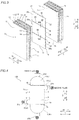
- the heat exchanger 100 includes multiple cores 1, header portions 2 (header portions 2a to 2d), and spacer portions 3.
- the cores 1 have two types of flow path portions 14 through which a first fluid on a high-temperature side and a second fluid on a low-temperature side flow, respectively, for example, and are configured to exchange heat between the first fluid and the second fluid.
- the flow path portions 14 through which multiple types of fluids flow are alternately stacked.
- the cores 1 include plate-fin type cores 1 in which fins 11 and separate plates 12 (dividers) are alternately stacked, as shown in Fig. 3 . In regions surrounded by these fins 11 and separate plates 12, individual paths of the flow path portions 14 are formed. On both side portions of the outer peripheral portions of the fins 11, side bars 13 are arranged, respectively. Each layer partitioned by the separate plates 12 and the side bars 13 constitutes one flow path portion 14. These fins 11, separate plates 12, and side bars 13 are bonded to each other by brazing so that the cores 1 are configured.
- each of the cores 1 has a rectangular parallelepiped shape. Between the cores 1 adjacent to each other, the spacer portions 3 are arranged.
- the cores 1 each include bonded surfaces 1a that faces the adjacent cores 1, a pair of first side surfaces 1b orthogonal to the bonded surfaces 1a, and a pair of second side surfaces 1c orthogonal to the first side surfaces 1b and the bonded surfaces 1a. These bonded surfaces 1a, first side surfaces 1b, and second side surfaces 1c each have a rectangular shape.
- the bonded surfaces 1a of the cores 1 adjacent to each other are welded to each other through the spacer portions 3 so that the multiple cores 1 are integrated.
- a direction in which the cores 1 are adjacent to each other is assumed as a direction X
- a direction along the long sides of the bonded surfaces 1a is assumed as a direction Z
- a direction along the short sides of the bonded surfaces 1a is assumed as a direction Y below.
- the bonded surfaces 1a of the cores 1 are plat surfaces including the outer surfaces of the separate plates 12 located outermost in the cores 1.
- ends of the multiple flow path portions 14 are exposed over the entire first side surfaces 1b, respectively.
- ends of the multiple flow path portions 14 are aligned along the direction X and exposed, respectively.
- the flow path portions 14 are exposed in ends on a Z1 side, and on the second side surfaces 1c on a Y2 side, the flow path portions 14 are exposed in ends on a Z2 side.
- header portions 2 are arranged on the first side surfaces 1b (the header portions 2a and 2b) and the second side surfaces 1c (the header portions 2c and 2d) different from the bonded surfaces 1a of the cores 1.
- These header portions 2 (2a to 2d) are provided to straddle the spacer portions 3 and cover the flow path portions 14 (see Fig. 2 ) of the multiple cores 1.
- Each of the header portions 2 (2a to 2d) is configured to guide the fluids into or out of each of the flow path portions 14 of the multiple cores 1 in one batch.
- Each of the header portions 2 (2a to 2d) is mounted on the first side surfaces 1b or the second side surfaces 1c by welding.
- the header portions 2a and 2b are examples of the "first header portion” in the present invention.
- the header portions 2c and 2d are examples of the "second header portion" in the present invention.
- the header portion 2a is provided on the first side surfaces 1b on a first end side (Z1 side) in the longitudinal direction of the cores 1, and the header portion 2b is provided on the first side surfaces 1b on a second end side (Z2 side) in the longitudinal direction of the cores 1. Over the entire the first side surfaces 1b, the flow path portions 14 are provided, and hence these header portions 2a and 2b are provided to cover the entire first side surfaces 1b, respectively.
- the header portion 2a is provided with an inflow/outflow port 21a through which the fluids flow in or flow out
- the header portion 2b is provided with an inflow/outflow port 21b through which the fluids flow in or flow out.
- the header portion 2c is provided on the second side surfaces 1c on a first end side (Y1 side) in the short-side direction of the cores 1, and the header portion 2d is provided on the second side surfaces 1c on a second end side (Y2 side) in the short-side direction of the cores 1. These header portions 2c and 2d are provided to cover only portions of the second side surfaces 1c on which the flow path portions 14 are exposed, respectively.
- the header portion 2c is provided with an inflow/outflow port 21c through which the fluids flow in or flow out, and the header portion 2d is provided with an inflow/outflow port 21d through which the fluids flow in or flow out.
- the spacer portions 3 are arranged between the bonded surfaces 1a of the cores 1 adjacent to each other, and are integrally fixed to the cores 1 on both side by welding.
- the spacer portions 3 include outer peripheral portions 3a circumferentially provided along the outer peripheral edges of the bonded surfaces 1a of the cores 1 and gap portions 3b and 3c provided in partial regions of the circumferential outer peripheral portions 3a.
- the spacer portions 3 each are constituted by three members of two first spacers 30a and 30b and one second spacer 30c. These first spacers 30a and 30b and second spacer 30c each have substantially the same thickness as the thicknesses of the separate plates 12 or a thickness less than the thicknesses of the separate plates 12.
- Figs. 1 to 3 exaggeratingly show the thicknesses of the first spacers 30a and 30b and the second spacer 30c.
- these first spacers 30a and 30b and second spacer 30c are arranged apart from each other in the longitudinal direction (see Fig. 1 ) of the bonded surfaces 1a (see Fig. 3 ), and the gap portions 3b an 3c are constituted by gaps between the first spacers 30a and 30b and the second spacer 30c.
- the outer peripheral portions 3a of the spacer portions 3 denotes entire portions along the outer peripheral edges of the bonded surfaces 1a, of the outer peripheral portions (sides) of the individual first spacers 30a and 30b and second spacer 30c.
- the spacer portions 3 are welded in a state where the same are held between the bonded surfaces 1a of the adjacent cores 1, and hence only the outer peripheral portions 3a along the outer peripheral edges of the bonded surfaces 1a are welded.
- Sides arranged inside the bonded surfaces 1a, of the sides of the first spacers 30a and 30b and the second spacer 30c, are not welded. In practice, as shown in Fig.
- the outer peripheral portions 3a of the spacer portions 3 are not flush with the outer peripheral edges of the bonded surfaces 1a but are arranged at positions deviated slightly inward from the outer peripheral edges.
- the outer peripheral portions 3a of the spacer portions 3 constitute the bottom surfaces of grooves slightly concaved with respect to the first side surfaces 1b and the second side surfaces 1c in a state where the spacer portions 3 are held by the bonded surfaces 1a, and allow filler materials (welding rods) to enter into the grooves during welding.
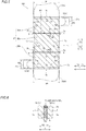
- the first spacers 30a and 30b each have a rectangular plate shape provided in the outer peripheral edge of a bonded surface 1a of a core 1 and a region inside the outer peripheral edge of the bonded surface 1a.
- the outer peripheral portions of the first spacers 30a and 30b are arranged along three sides of the outer peripheral edge of the bonded surface 1a of the core 1.
- the first spacers 30a and 30b are provided along the outer peripheral edge of the bonded surface 1a closer to one of the first side surfaces 1b and the respective outer peripheral edges of the bonded surface 1a closer to both of the second side surfaces 1c.
- Second sides 32 of the first spacer 30a each have a length more than the width W2 of the header portion 2c in the direction Z along the second side surfaces 1c, and extend from an end closer to one of the first side surfaces 1b to the gap portion 3b.
- Second sides 32 of the first spacer 30b each have a length more than the width W2 of the header portion 2d in the direction Z along the second side surfaces 1c, and extend from an end closer to the other of the first side surfaces 1b to the gap portion 3c.
- Internal sides 33 of the first spacers 30a and 30b are along the gap portions 3b and 3c, respectively.
- the first spacer 30a functions as a partition wall that partitions an interior space of the header portion 2a and a gap CL (an arrangement region of each of the spacer portions 3) between the bonded surfaces 1a of the cores 1 by the first side 31 (and a welded portion of the first side 31), and functions as a partition wall that partitions an interior space of the header portion 2c and the gap CL between the bonded surfaces 1a of the cores 1 by the second side 32 (and a welded portion of the second side 32) on the Y1 side.
- the first spacer 30b functions as a partition wall that partitions an interior space of the header portion 2b and the gap CL between the bonded surfaces 1a of the cores 1 by the first side 31 (and the welded portion), and functions as a partition wall that partitions an interior space of the header portion 2d and the gap CL between the bonded surfaces 1a of the cores 1 by the second side 32 (and the welded portion) on the Y1 side.
- the second spacer 30c is provided between a pair of first spacers 30a and 30b.
- the second spacer 30c is arranged apart from the pair of first spacers 30a and 30b through the gap portions 3b and 3c, respectively.
- a pair of sides 35 of the second spacer 30c extending in the direction Z is along the outer peripheral edges (sides) of the bonded surfaces 1a closer to the second side surfaces 1c, and the length thereof in the direction Z is equal to a distance between the gap portion 3b and the gap portion 3c.
- the outer peripheral portions 3a of the spacer portions 3 are constituted by the respective first sides 31 and second sides 32 of the first spacers 30a and 30b and the sides 35 of the second spacers 30c extending in the direction Z, and are circumferentially formed over the substantially entire circumferences (entire circumferences excluding portions on which the gap portions 3b and 3c are located) of the outer peripheral edges of the bonded surfaces 1a as a whole.
- weld sites between the cores 1 and the spacer portions 3 are substantially entire circumferences of the outer peripheral edges of the bonded surfaces 1a excluding the portions on which the gap portions 3b and 3c are located.
- weld lines formed by welding are broken at the portions on which the gap portions 3b and 3c are located.
- ends (starting points or end points) of the weld sites are located at the gap portions 3b and 3c.
- the gap portions 3b and 3c are provided at positions where a temperature gradient on the bonded surfaces 1a of the cores 1 is relatively shallow.
- the temperature gradient varies by the operational conditions (the temperatures (the inlet temperature, the outlet temperature) of two types of fluids, the types, flow rates, working pressures, etc. of the fluids) of the heat exchanger 100.
- the temperature gradient is obtained by a simulation or the like according to these operational conditions.
- the temperature gradient is mainly generated in a direction along the flow direction of the fluids flowing through the flow path portions 14 (a direction in which the flow path portions 14 extend (the longitudinal direction of the cores 1)). Therefore, in the case of the first embodiment, the positions of the gap portions (3b and 3c) can be determined by the temperature gradient in the direction Z.
- An example of the temperature gradient in the direction Z (the longitudinal direction of the cores 1) in central portions in the direction Y is shown in Fig. 7 .
- a position in the direction Z is shown by percentage, assuming a Z2-side end of the bonded surface 1a as 0% and a Z1-side end of the bonded surface 1a as 100%.
- the vertical axis represents absolute temperature (K), and as the slope of a graph is small, a temperature gradient in the direction Z is shallow.
- the temperature gradient is relatively shallow (the slope is small) in regions shown by A1 and A2 as compared with other sites.
- the positions of the gap portions 3b and 3c correspond to positions P1 and P2 in the regions A1 and A2, respectively.
- the gap portions 3b and 3c are arranged at positions that are different from regions in which the header portions 2 (2a to 2d) are arranged and are closer to the header portions 2 (2a to 2d) in the regions in which the temperature gradient is relatively shallow.
- the regions in which the header portions 2 are arranged correspond to ranges with a width W2 on the Z2 side (header portion 2d) and a width W2 on the Z1 side (header portion 2c). In this manner, the positions in which the gap portions 3b and 3c are arranged are determined.
- the positions in which the gap portions 3b and 3c are arranged are located at substantially the same distance from the first side surfaces 1b on the Z1 side and the first side surfaces 1b on the Z2 side, respectively, but the positions in which the gap portions 3b and 3c are arranged may be at completely different distances.
- the lengths of the second sides 32 of the first spacer 30a and the lengths of the second sides 32 of the first spacer 30b may be different from each other.
- the gap portions 3b and 3c are provided to pass through regions between the first spacers 30a and 30b and the second spacer 30c from one of the second side surfaces 1c to the other of the second side surfaces 1c on each of the bonded surfaces 1a of the cores 1. As shown in Fig. 5 , both the gap portions 3b and 3c are provided to linearly extend in the direction Y with groove widths W3 less than the width W1 of the header portion 2a (2b), the width W2 of the header portion 2c (2d), and the lengths of the sides 32 and sides 35.
- the groove widths W3 of the gap portions 3b and 3c are preferably less than the widths of the regions (A1 and A2 in Fig.
- both ends (the ends of the weld sites) of the gap portions 3b and 3c in a width direction are preferably arranged to fit into the regions (A1 and A2 in Fig. 7 ) in which the temperature gradient is relatively shallow.
- the groove widths of the gap portions 3b and 3c may be different in magnitude from each other.
- the weld sites of the first sides 31 and the second sides 32 function as the partition walls that partition the interior spaces of the header portions 2 (2a to 2d) and the gap CL (the region in which each of the spacer portions 3 is arranged) between the bonded surfaces 1a of the cores 1.
- the interior spaces of the header portions 2 and the gap CL between the bonded surfaces 1a of the cores 1 may be communicated with each other, and leakage of the fluids from the interior spaces of the header portions 2 to the gap CL between the bonded surfaces 1a of the cores 1 (the region in which each of the spacer portions 3 is arranged) may occur.
- the leaking fluids pass through a small gap formed between the bonded surface 1a and the first spacer 30a.
- the remaining portions of the outer peripheral portion of the first spacer 30a are welded, and hence the leaking fluids can only be leaked to the Z2 side, and reach the gap portion 3b.
- the gap portion 3b is a linear flow path, and hence occurrence of the leakage of the fluids from the first spacer 30a can be easily determined by detecting the fluids that flow out of the gap portion 3b.
- the leaking fluids reach the gap portion 3c, and hence the leakage of the fluids from the first spacer 30b through the gap portion 3c can be easily determined.
- the cover plates 5 include openable and closable detection holes 5a, and the detection holes 5a are generally closed. At the time of leakage testing, the detection holes 5a of the cover plates 5 are opened, and the leaking fluids can be detected through the detection holes 5a.
- the first fluid flows into the inflow/outflow port 21a of the header portion 2a. Then, the first fluid flowing in from the header portion 2a flows through the cores 1 (flow path portions 14) vertically downward (in a direction Z2), flows to the Y2-direction side in an L-shape, and flows out through the inflow/outflow port 21d of the header portion 2d.
- the second fluid flows into the inflow/outflow port 21c of the header portion 2c. Then, the second fluid flowing in from the header portion 2c flows through the cores 1 (flow path portions 14) to the Y2-direction side, flows vertically downward (in the direction Z2) in an L-shape, and flows out through the inflow/outflow port 21b of the header portion 2b.
- the outer peripheral portions 3a circumferentially provided along the outer peripheral edges of the bonded surfaces 1a of the cores 1 and the gap portions 3b and 3c provided in the partial regions of the circumferential outer peripheral portions 3a are provided in the spacer portions 3, whereby the weld sites between the spacer portions 3 and the cores 1 (i.e. the outer peripheral portions 3a of the spacer portions 3) can be circumferentially formed along the outer peripheral edges of the bonded surfaces 1a while the gap portions 3b and 3c are ensured.
- the gap portions 3b and 3c are provided at positions (the regions A1 and A2 in Fig. 7 ) where the temperature gradient on the bonded surfaces 1a of the cores 1 is relatively shallow, considering that the ends (the starting points or the end points of welding) of the weld sites in which a stress is likely to be concentrated are located in the gap portions 3b and 3c, whereby the ends (the gap portions 3b and 3c) of the weld sites can also be arranged at the positions where the temperature gradient is relatively shallow.
- the ends of the weld sites can be arranged in regions of the bonded surfaces 1a in which a stress caused by deformation following a temperature change is relatively small, and hence an increase in stress can be suppressed even if a stress is concentrated in the ends of the weld sites.
- the bonding strength between the spacer portions 3 and the cores 1 can be improved while an increase in stress in the ends (the gap portions 3b and 3c) of the weld sites can be suppressed, and hence the spacer portions 3 can sufficiently withstand a stress under operational conditions where a temperature difference between a high-temperature side and a low-temperature side is large.
- the first spacers 30a and 30b each having a rectangular plate shape and provided in the outer peripheral edges of the bonded surfaces 1a of the cores 1 and the regions inside the outer peripheral edges of the bonded surfaces 1a are provided in the spacer portions 3.
- the spacer portions themselves can be rendered robust to an increase in stress caused by the deformation of the bonded surfaces 1a of the cores 1.
- the outer peripheral portions (the first sides 31 and the second sides 32) of the first spacers 30a and 30b each having a rectangular plate shape are arranged along the three sides of the outer peripheral edges of the bonded surfaces 1a of the cores 1.
- the large-size first spacer portions 30a and 30b each having a rectangular plate shape can be provided, and the weld sites of the first spacers 30a and 30b can be formed in a wide range over the three sides of the outer peripheral edges of the bonded surfaces 1a of the cores 1. Consequently, the stiffness of the first spacers 30a and 30b themselves and the bonding strength between the first spacers 30a and 30b and the cores 1 can be further improved.
- ends of the flow path portions 14 in the vicinity of the bonded surfaces 1a may be deformed due to heat during the welding.
- the stiffness of the first spacers 30a and 30b is improved, and hence deformation of the ends of the flow path portions 14 during welding can also be suppressed.
- the leaking fluids passing between the first spacer 30a (30b) and the bonded surface 1a can be sent to the gap portion 3b (3c).
- the leakage from the weld sites of the first spacers 30a and 30b can be checked simply by detecting the fluids in the gap portions 3b and 3c at the time of leakage testing, and hence the leakage of the fluids can be easily detected even when the first spacers 30a and 30b are increased in size.
- the pair of first spacers 30a and 30b provided closer to a pair of first side surfaces 1b that sandwiches the bonded surface 1a therebetween, respectively, and the second spacer 30c having a rectangular plate shape and arranged through the gap portions 3b and 3c with respect to the pair of first spacers 30a an 30b are provided in each of the spacer portions 3.
- the spacer portions 3 can be provided in a wide range over the substantially entire bonded surfaces 1a of the cores 1, and hence the stiffness of the entire spacer portions 3 and the bonding strength between the spacer portions 3 and the cores 1 can be improved.
- the leakage of the fluids occurring in each of the pair of first spacers 30a an 30b can be detected from the respective gap portions 3b and 3c between the first spacers 30a and 30b and the second spacer 30c, and hence the leakage of the fluids can be easily detected.
- the gap portions 3b and 3c are provided to pass through the regions between the first spacers 30a and 30b and the second spacer 30c from one of the second side surfaces 1c to the other of the second side surfaces 1c.
- the gap portions 3b and 3c as flow paths for detecting the leaking fluids are formed in a simple shape, whereby the leaking fluids can be promptly guided to the outside of the gap portions 3b an 3c, and the leaking fluids can be easily detected from the sides of the second side surfaces 1c.
- the gap portions 3b and 3c are arranged at the positions that are different from the regions in which the header portions 2 (2a to 2d) are arranged and that are closer to the header portions 2 (2a to 2d) in the regions in which the temperature gradient on the bonded surfaces 1a of the cores 1 is relatively shallow.
- distances between the header portions 2 (2a to 2d) and the gap portions 3b and 3c can be reduced. Therefore, the fluids leaking from the sides of the header portions 2 (2a to 2d) through the spacer portions 3 can be more easily and reliably detected while the influence of a temperature change on the ends (the gap portions 3b and 3c) of the weld sites is suppressed.
- FIG. 8 A second embodiment is now described with reference to Fig. 8 .
- a heat exchanger 200 provided with spacer portions 103 different from the aforementioned first embodiment in which the spacer portions 3 are constituted by the first spacers 30a and 30b each having a rectangular plate shape and the second spacers 30c each having a rectangular plate shape is described.
- Structures of the heat exchanger 200 according to the second embodiment other than the structure of the spacer portions 103 are similar to those of the aforementioned first embodiment, and hence the structures are denoted by the same reference numerals, to omit the description.
- the spacer portions 103 of the heat exchanger 200 are constituted by first spacers 130 each having a rectangular plate shape, L-shaped spacers 140, and linear spacers 150.
- gap portions 103b and 103c both are arranged at positions near first side surfaces 1b closer to second ends (Z2 side) than first ends (Z1 side) in the longitudinal direction of cores 1.
- the first spacers 130 each are provided in the outer peripheral edge of a bonded surface 1a of a core 1 and a region inside the outer peripheral edge.
- the outer peripheral portion of each of the first spacers 130 is provided along the outer peripheral edge (side) of the bonded surface 1a of the core 1 closer to a first side surface 1b on the Z1 side and the outer peripheral edges (sides) of the bonded surface 1a of the core 1 closer to both of second side surfaces 1c.
- a first side 131 of each of the first spacers 130 closer to the first side surface 1b has a length substantially equal to the width W1 (i.e. the entire length of the first side surface 1b in a direction Y (the short-side direction of the core 1)) of a header portion 2a.
- Second sides 132 of each of the first spacers 130 closer to the second side surfaces 1c each have a length more than the width W2 of a header portion 2c in a direction Z (the longitudinal direction of the core 1), and extend from an end closer to one of the first side surfaces 1b to the gap portion 103b.
- the second sides 132 each have a length equal to or more than a half of the outer peripheral edge closer to each of the second side surfaces 1c, which extends in the direction Z.
- the L-shaped spacers 140 each are provided along two sides of the outer peripheral edge of the bonded surface 1a of the core 1 closer to a first side surface 1b on the Z2 side and the outer peripheral edge of the bonded surface 1a of the core 1 closer to a second side surface 1c on a Y2 side. Therefore, the spacers 140 each are provided along the outer peripheral edge of the bonded surface 1a of the core 1, but not provided in the region inside the outer peripheral edge.
- a side 141 of each of the spacers 140 closer to the first side surface 1b has a length substantially equal to the width W1 (i.e. the entire length of the first side surface 1b in the direction Y) of the header portion 2a.
- a side 142 of each of the spacers 140 closer to the second side surface 1c has a length more than the width W2 of a header portion 2d, and extends from an end closer to the first side surface 1b on the Z2 side to the gap portion 103b.
- the linear spacers 150 each have a narrow plate shape provided along the outer peripheral edge (side) of the bonded surface 1a of the core 1 closer to a second side surface 1c on a Y1 side. Therefore, the spacers 150 each are provided along the outer peripheral edge of the bonded surface 1a of the core 1, but not provided in the region inside the outer peripheral edge.
- a side 151 of each of the spacers 150 extends from the gap portion 103b to the gap portion 103c in the direction Z.
- the first spacers 130 each function as a partition wall that partitions an interior space of the header portion 2a and a gap CL between bonded surfaces 1a of the cores 1, and function as a partition wall that partitions an interior space of the header portion 2c and the gap CL between the bonded surfaces 1a of the cores 1.
- the spacers 140 each function as a partition wall that partitions an interior space of the header portion 2b and the gap CL between the bonded surfaces 1a of the cores 1, and function as a partition wall that partitions an interior space of the header portion 2d and the gap CL between the bonded surfaces 1a of the cores 1.
- the outer peripheral portions 103a of the spacer portions 103 are constituted by the first sides 131 and the second sides 132 of the first spacers 130, the sides 141 and the sides 142 of the spacers 140, and the sides 151 of the spacers 150, and are circumferentially formed over the substantially entire circumferences (entire circumferences excluding portions on which the gap portions 103b and 103c are located) of the outer peripheral edges of the bonded surfaces 1a as a whole.
- the gap portions 103b and 103c are provided at positions closer to one (Z2 side) of a pair of first side surfaces 1b, which is orthogonal to the bonded surface 1a and sandwiches the bonded surface 1a therebetween, than the other (Z1 side) of the pair of first side surfaces 1b in a region in which a temperature gradient is relatively shallow in the bonded surface 1a of the core 1.
- the gap portion 103b is provided at a position on the Z1 side with respect to the header portion 2d and closer to the header portion 2d in a region in which the temperature gradient is relatively shallow in the bonded surface 1a of the core 1.
- the gap portion 103c is arranged on the Y1 side opposite to the header portion 2d and in the vicinity of the first side surface 1b on the Z2 side.
- the gap portions 103b and 103c have widths W4 and W5, respectively, less than the width W1 of the header portion 2a (2b), the width W2 of the header portion 2c (2d), and the lengths of the sides 132, the side 142, and the side 151.
- W4 and W5 widths W4 and W5
- the gap portions 103b and 103c are communicated with each other.
- the groove width W4 of the gap portion 103b and the groove width W5 of the gap portion 103c each are preferably less than the width of the region in which the temperature gradient is relatively shallow, and both ends (ends of weld sites) of the gap portions 103b and 103c in a width direction are preferably arranged to fit into the region in which the temperature gradient is relatively shallow.
- the outer peripheral portions 103a circumferentially provided along the outer peripheral edges of the bonded surfaces 1a of the cores 1 and the gap portions 103b and 103c provided in partial regions of the circumferential outer peripheral portions 103a are provided in the spacer portions 103.
- the gap portions 103b and 103c are provided at positions where the temperature gradient on the bonded surface 1a of the core 1 is relatively shallow.
- each of the first spacers 130 having a rectangular plate shape extends from the end closer to the other (Z1 side) of the first side surfaces 1b to the gap portion 103b closer to one (Z2 side) of the first side surfaces 1b on the bonded surface 1a of the core 1.
- the large-size first spacers 130 over a wide range from the end closer to the other (Z1 side) of the first side surfaces 1b to the gap portion 103b closer to one (Z2 side) of the first side surfaces 1b can be provided, and hence the stiffness of the first spacers 130 can be further improved. Also in this case, leakage from the weld sites of the first spacers 130 can be checked simply by detecting the fluids in the gap portions 103b and 103c, and hence the leakage of the fluids can be easily detected.
- the comparative example is an example of providing two L-shaped spacers 230a and 230b to cover only portions in which header portions 2 (2a to 2d) are placed (see Fig. 5 ).
- the spacer 230a is provided along the outer peripheral edge of a bonded surface 1a corresponding to the header portions 2a and 2c (see Fig. 5 ).
- the spacer 230b is provided along the outer peripheral edge of the bonded surface 1a corresponding to the header portions 2b and 2d (see Fig. 5 ).
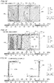
- Figs. 9, 10, and 11 show a temperature distribution on each of the spacer portions 3 of the heat exchanger 100 according to the first embodiment, a temperature distribution on each of the spacer portions 103 of the heat exchanger 200 according to the second embodiment, and a temperature distribution on the spacer portion 203 according to the comparative example, respectively. Temperature is illustrated by dividing a temperature range from less than 340 K to 700 K in terms of absolute temperature into 10 stages every 40 K and differently hatching the stages. The temperature distributions on the spacer portions in Figs. 9, 10, and 11 are substantially similar. It is found from Figs.
- the gap portions 3b and 3c are arranged to fit into the same region of the temperature range, and the gap portions 3b and 3c (103b and 103c) are arranged at the positions where the temperature gradient is relatively shallow.
- Figs. 12, 13, and 14 show a stress distribution on each of the spacer portions 3 of the heat exchanger 100 according to the first embodiment, a stress distribution on each of the spacer portions 103 of the heat exchanger 200 according to the second embodiment, and a stress distribution on the spacer portion 203 according to the comparative example, respectively.
- Stress is illustrated by dividing a stress range from less than 30 MPa (S1) to at least 270 MPa (S10) into 10 stages (S1 to S10) every 30 MPa and differently hatching the stages.
- the weld sites of the spacer portions are linearly provided along the outer peripheral portions, and hence ends C (the starting points or the end points of welding) of the weld sites have the lowest strength.
- the ends C of the weld sites are the positions of the gap portions 3b and 3c in Fig. 12 (the spacer portions 3), the positions of the gap portions 103b and 103c in Fig. 13 (the spacer portions 103), and both ends of the spacer 230a (230b) in Fig. 14 (the spacer portion 203).
- a stress is kept to a level of S1 to S4, which is less than 120 MPa, at each of the positions of the gap portions 3b and 3c, as shown in Fig. 12 .
- a stress is kept to a level of S1 to S5, which is less than 150 MPa, at each of the gap portions 103b and 103c, as shown in Fig. 13 .
- a stress is increased to a level of S10 (at least 270 MPa) particularly in a Y2 side end of the spacer 230a and a Y1 side end of the spacer 230b as to both ends of the spacer 230a (230b).
- the spacers are shaped into a large-size rectangular plate as the first spacers 30a and 30b and the second spacers 30c of the heat exchanger 100 according to the first embodiment and the first spacers 130 of the heat exchanger 200 according to the second embodiment, whereby the stiffness of the spacers themselves are improved.
- portions other than the ends of the weld sites can withstand a higher stress as well.
- the present invention is not restricted to this. According to the present invention, three or more types of fluids may flow through the cores.
- the present invention is not restricted to this.
- the gap portions may not penetrate but may be provided on both sides closer to the second side surfaces.
- the gap portions may be provided in a curved line.
- the present invention is not restricted to this.
- the first spacers each may have a shape other than the rectangular shape.
- the shapes of inner portions (sides 33; see Fig. 5 ) not along the outer peripheral edges of the bonded surfaces are arbitrary.
- first spacers (30a, 30b, 130) along the three sides of the outer peripheral edges of the bonded surfaces
- the present invention is not restricted to this.
- the first spacers each may have a shape along only two sides of the outer peripheral edges.
- the present invention is not restricted to this.
- the lengths of the first sides of the first spacers may be smaller than the entire lengths of the outer peripheral edges closer to the first side surfaces so far as the same are equal to or more than the widths of the header portions. More specifically, as shown in Fig.
- first sides 31 of the first spacers 30a and 30b closer to the first side surfaces 1b each have a length equal to or more than the width W1 of the header portion 2a (2b) on the bonded surfaces 1a.
- first spacers 130 shown in Fig. 8 the first spacers 130 shown in Fig. 8 .
- the present invention is not restricted to this. According to the present invention, any number of spacers constituting the spacer portions may be employed.
Landscapes
- Engineering & Computer Science (AREA)
- Physics & Mathematics (AREA)
- Thermal Sciences (AREA)
- Mechanical Engineering (AREA)
- General Engineering & Computer Science (AREA)
- Heat-Exchange Devices With Radiators And Conduit Assemblies (AREA)
Abstract
Description
- The present invention relates to a heat exchanger, and more particularly, it relates to a heat exchanger including multiple cores and spacer portions arranged between bonded surfaces of the adjacent cores.
- A heat exchanger including multiple cores and spacer portions arranged between bonded surfaces of the adjacent cores is known in general. A heat exchanger like this is disclosed in Japanese Patent Laying-Open No.
2012-255646 - In Japanese Patent Laying-Open No.
2012-255646 - Patent Document 1: Japanese Patent Laying-Open No.
2012-255646 - In Japanese Patent Laying-Open No.
2012-255646 - The header portion is configured to guide the fluids into or out of the flow path portions of each core in one batch by straddling the spacer portions and covering ports of the flow path portions of the multiple cores. Thus, the spacer portions also function as partition walls between the bonded surfaces of the cores to maintain the internal space of the header portion at a predetermined stress. Therefore, when there is poor weld in the weld sites between the spacer portions and the cores, the fluids may be leaked to clearance gaps between the cores. Thus, when the heat exchanger is manufactured, the leakage of the fluids from the header portion to the clearance gaps between the cores is tested. Therefore, the spacer portions each preferably have a shape enabling easy detection of the leakage of the fluids from the header portion to between the cores in the leakage testing.
- The present invention has been proposed in order to solve the aforementioned problem, and one object of the present invention is to provide a heat exchanger including spacer portions that enable easy detection of leakage of fluids from a header portion to between cores and are capable of sufficiently withstanding a stress under operational conditions where a temperature difference between a high-temperature side and a low-temperature side is large.
- In order to attain the aforementioned object, a heat exchanger according to an aspect of the present invention includes multiple cores in which flow path portions through which multiple types of fluids flow are alternately stacked, and a spacer portion arranged between bonded surfaces of the cores adjacent to each other and integrally fixed to the cores on both sides by welding, the spacer portion includes an outer peripheral portion circumferentially provided along outer peripheral edges of the bonded surfaces of the cores and a gap portion provided in a partial region of the circumferential outer peripheral portion, and the gap portion is provided at a position where a temperature gradient on the bonded surfaces of the cores is relatively shallow.
- In the heat exchanger according to this aspect of the present invention, as hereinabove described, the outer peripheral portion circumferentially provided along the outer peripheral edges of the bonded surfaces of the cores and the gap portion provided in the partial region of the circumferential outer peripheral portion are provided in the spacer portion, whereby a weld site between the spacer portion and the cores (i.e. the outer peripheral portion of the spacer portion) can be circumferentially formed along the outer peripheral edges of the bonded surfaces while the gap portion is ensured. Consequently, leakage of the fluids can be easily detected through the gap portion, and the circumferential weld site enables an increase in a bond area between the spacer portion and the cores so that the bonding strength can be improved. Furthermore, the gap portion is provided at the position where the temperature gradient on the bonded surfaces of the cores is relatively shallow, considering that an end (a starting point or an end point of welding) of the weld site in which a stress is likely to be concentrated is located in the gap portion, whereby the end of the weld site can also be arranged at the position where the temperature gradient is relatively shallow. Thus, the end of the weld site can be arranged in a region of the bonded surfaces in which a stress caused by deformation following a temperature change is relatively small, and hence an increase in stress can be suppressed even if a stress is concentrated in the end of the weld site. Thus, the bonding strength between the spacer portion and the cores can be improved while an increase in stress in the end (the gap portion) of the weld site can be suppressed, and hence the spacer portion can sufficiently withstand a stress under operational conditions where a temperature difference between a high-temperature side and a low-temperature side is large.
- Preferably in the aforementioned heat exchanger according to this aspect, the spacer portion includes a first spacer having a rectangular plate shape and provided on the outer peripheral edges of the bonded surfaces of the cores and regions inside the outer peripheral edges of the bonded surfaces. According to this structure, the stiffness of the first spacer itself can be improved as compared with the structure of providing the spacer in only the outer peripheral edges of the bonded surfaces of the cores. Thus, the spacer portion (the first spacer) itself can be rendered robust to an increase in stress caused by the deformation of the bonded surfaces of the cores.
- Preferably in this case, the bonded surfaces of the cores each have a rectangular shape, and the outer peripheral portion of the first spacer having the rectangular plate shape is arranged along three sides of the outer peripheral edges of the bonded surfaces of the cores. According to this structure, the large-size first spacer portion having a rectangular plate shape can be provided, and the weld site of the first spacer can be formed in a wide range over the three sides of the outer peripheral edges of the bonded surfaces of the cores. Consequently, the stiffness of the first spacer itself and the bonding strength between the first spacer and the cores can be further improved.
- Preferably, the aforementioned structure in which the spacer portion includes the first spacer having the rectangular plate shape further includes a first header portion provided on first side surfaces of the cores orthogonal to the bonded surfaces and a second header portion provided on second side surfaces of the cores orthogonal to the first side surfaces and the bonded surfaces, and on the bonded surfaces, a first side of the first spacer having the rectangular plate shape, which is closer to the first side surfaces, has a length equal to or more than the width of the first header portion, and a second side of the first spacer, which is closer to the second side surfaces, has a length equal to or more than the width of the second header portion, and extends to the gap portion. According to this structure, the first spacer having the rectangular plate shape can function as a partition wall that prevents leakage of the fluids to a gap between the cores in the first header portion and the second header portion. The second side of the first spacer extends to the gap portion, whereby even when there is poor weld leading to leakage, the leaking fluids passing between the first spacer and the bonded surfaces can be sent to the gap portion. Consequently, leakage from the weld site of the first spacer can be checked simply by detecting the fluids in the gap portion at the time of leakage testing, and hence the leakage of the fluids can be easily detected even when the first spacer is increased in size.
- Preferably in this case, on the bonded surfaces of the cores, the spacer portion includes a pair of the first spacers provided closer to a pair of the first side surfaces that sandwiches each of the bonded surfaces therebetween, respectively, and a second spacer having a rectangular plate shape, provided between the pair of first spacers, and arranged through the gap portion with respect to each of the pair of first spacers. According to this structure, due to the pair of first spacers and the second spacer between the pair of first spacers, the spacer portion can be provided in a wide range over the substantially entire bonded surfaces of the cores, and hence the stiffness of the entire spacer portion and the bonding strength between the spacer portion and the cores can be improved. Also in this case, leakage of the fluids occurring in each of the pair of first spacers can be detected from the gap portion between each of the first spacers and the second spacer, and hence the leakage of the fluids can be easily detected.
- Preferably in the aforementioned structure in which the spacer portion includes the pair of first spacers and the second spacer having the rectangular plate shape and arranged through the gap portion with respect to each of the pair of first spacers, on the bonded surfaces of the cores, the gap portion is provided to pass through a region between the first spacer and the second spacer from one of the second side surfaces to the other of the second side surfaces. According to this structure, the gap portion as a flow path for detecting the leaking fluids is formed in a simple shape, whereby the leaking fluids can be promptly guided to the outside of the gap portion, and the leaking fluids can be easily detected from the sides of the second side surfaces.
- Preferably in the aforementioned structure in which the spacer portion includes the first spacer having the rectangular plate shape, on the bonded surfaces of the cores, the gap portion is provided at a position closer to one of a pair of first side surfaces, which is orthogonal to the bonded surfaces and sandwiches each of the bonded surfaces therebetween, than the other of the pair of first side surfaces in a region in which the temperature gradient is relatively shallow in the bonded surfaces of the cores, and the first spacer having the rectangular plate shape extends from an end closer to the other of the first side surfaces to the gap portion closer to the one of the first side surfaces on the bonded surfaces of the cores. According to this structure, the large-size first spacer over a wide range from an end closer to the other of the first side surfaces to the gap portion closer to one of the first side surfaces can be provided, and hence the stiffness of the first spacer can be improved. Also in this case, the leakage from the weld site of the first spacer can be checked simply by detecting the fluids in the gap portion, and hence the leakage of the fluids can be easily detected.
- Preferably, the aforementioned heat exchanger according to this aspect further includes a header portion arranged on side surfaces different from the bonded surfaces of the cores and provided to straddle the spacer portion and to cover the flow path portions of the multiple cores, and the gap portion is arranged at a position that is different from a region in which the header portion is arranged and that is closer to the header portion in regions in which the temperature gradient on the bonded surfaces of the cores is relatively shallow. According to this structure, a distance between the header portion and the gap portion can be reduced. Therefore, the fluids leaking from the side of the header portion through the spacer portion can be more easily and reliably detected while the influence of a temperature change on the end (the gap portion) of the weld site is suppressed.
- According to the present invention, as hereinabove described, the heat exchanger including the spacer portion that enables easy detection of the leakage of the fluids from the header portion to between the cores and are capable of sufficiently withstanding a stress under the operational conditions where a temperature difference between a high-temperature side and a low-temperature side is large can be provided.
-
- [
Fig. 1 ] A perspective view showing the structure of a heat exchanger according to a first embodiment of the present invention. - [
Fig. 2 ] An exploded perspective view showing the structure of the heat exchanger according to the first embodiment of the present invention. - [
Fig. 3 ] An exploded perspective view showing cores and a spacer portion of the heat exchanger according to the first embodiment of the present invention. - [
Fig. 4 ] A side elevational view of the heat exchanger according to the first embodiment of the present invention, as viewed from an X-direction side. - [
Fig. 5 ] A diagram of a bonded surface side of a core for illustrating the structure of the spacer portion of the heat exchanger according to the first embodiment of the present invention. - [
Fig. 6 ] A schematic partial sectional view for illustrating a weld site between the adjacent core and the spacer portion. - [
Fig. 7 ] An example of a temperature-position curve diagram for illustrating a temperature gradient in the core. - [
Fig. 8 ] A diagram of a bonded surface side of a core for illustrating the structure of a spacer portion of a heat exchanger according to a second embodiment of the present invention. - [
Fig. 9 ] A temperature distribution chart showing an example of operational conditions where a temperature difference between a high-temperature side and a low-temperature side is large in the heat exchanger according to the first embodiment of the present invention. - [
Fig. 10 ] A temperature distribution chart showing an example of operational conditions where a temperature difference between a high-temperature side and a low-temperature side is large in the heat exchanger according to the second embodiment of the present invention. - [
Fig. 11 ] A temperature distribution chart showing an example of operational conditions where a temperature difference between a high-temperature side and a low-temperature side is large according to a comparative example. - [
Fig. 12 ] A diagram showing a simulation result of a stress distribution for a temperature distribution shown inFig. 9 on the spacer portion according to the first embodiment. - [
Fig. 13 ] A diagram showing a simulation result of a stress distribution for a temperature distribution shown inFig. 10 on the spacer portion according to the second embodiment. - [
Fig. 14 ] A diagram showing a simulation result of a stress distribution for a temperature distribution shown inFig. 11 on a spacer portion according to the comparative example. - Embodiments of the present invention are hereinafter described on the basis of the drawings.
- The structure of a
heat exchanger 100 according to this embodiment is now described with reference toFigs. 1 to 7 . - As shown in
Figs. 1 and2 , theheat exchanger 100 includesmultiple cores 1, header portions 2 (header portions 2a to 2d), andspacer portions 3. - As shown in
Fig. 2 , thecores 1 have two types offlow path portions 14 through which a first fluid on a high-temperature side and a second fluid on a low-temperature side flow, respectively, for example, and are configured to exchange heat between the first fluid and the second fluid. In thecores 1, theflow path portions 14 through which multiple types of fluids flow are alternately stacked. Thecores 1 include plate-fin type cores 1 in whichfins 11 and separate plates 12 (dividers) are alternately stacked, as shown inFig. 3 . In regions surrounded by thesefins 11 andseparate plates 12, individual paths of theflow path portions 14 are formed. On both side portions of the outer peripheral portions of thefins 11, side bars 13 are arranged, respectively. Each layer partitioned by theseparate plates 12 and the side bars 13 constitutes oneflow path portion 14. Thesefins 11,separate plates 12, and side bars 13 are bonded to each other by brazing so that thecores 1 are configured. - As shown in
Fig. 3 , each of thecores 1 has a rectangular parallelepiped shape. Between thecores 1 adjacent to each other, thespacer portions 3 are arranged. Thecores 1 each include bondedsurfaces 1a that faces theadjacent cores 1, a pair of first side surfaces 1b orthogonal to the bondedsurfaces 1a, and a pair of second side surfaces 1c orthogonal to the first side surfaces 1b and the bondedsurfaces 1a. These bondedsurfaces 1a,first side surfaces 1b, and second side surfaces 1c each have a rectangular shape. The bonded surfaces 1a of thecores 1 adjacent to each other are welded to each other through thespacer portions 3 so that themultiple cores 1 are integrated. For convenience, a direction in which thecores 1 are adjacent to each other is assumed as a direction X, a direction along the long sides of the bondedsurfaces 1a is assumed as a direction Z, and a direction along the short sides of the bondedsurfaces 1a is assumed as a direction Y below. - The bonded surfaces 1a of the
cores 1 are plat surfaces including the outer surfaces of theseparate plates 12 located outermost in thecores 1. On the pair offirst side surfaces 1b, ends of the multipleflow path portions 14 are exposed over the entirefirst side surfaces 1b, respectively. On the pair of second side surfaces 1c, ends of the multipleflow path portions 14 are aligned along the direction X and exposed, respectively. On the second side surfaces 1c on a Y1 side, theflow path portions 14 are exposed in ends on a Z1 side, and on the second side surfaces 1c on a Y2 side, theflow path portions 14 are exposed in ends on a Z2 side. - As shown in
Fig. 4 , a total of fourheader portions 2 are arranged on thefirst side surfaces 1b (theheader portions header portions surfaces 1a of thecores 1. These header portions 2 (2a to 2d) are provided to straddle thespacer portions 3 and cover the flow path portions 14 (seeFig. 2 ) of themultiple cores 1. Each of the header portions 2 (2a to 2d) is configured to guide the fluids into or out of each of theflow path portions 14 of themultiple cores 1 in one batch. Each of the header portions 2 (2a to 2d) is mounted on the first side surfaces 1b or the second side surfaces 1c by welding. Theheader portions header portions - The
header portion 2a is provided on the first side surfaces 1b on a first end side (Z1 side) in the longitudinal direction of thecores 1, and theheader portion 2b is provided on the first side surfaces 1b on a second end side (Z2 side) in the longitudinal direction of thecores 1. Over the entire thefirst side surfaces 1b, theflow path portions 14 are provided, and hence theseheader portions first side surfaces 1b, respectively. Theheader portion 2a is provided with an inflow/outflow port 21a through which the fluids flow in or flow out, and theheader portion 2b is provided with an inflow/outflow port 21b through which the fluids flow in or flow out. - The
header portion 2c is provided on the second side surfaces 1c on a first end side (Y1 side) in the short-side direction of thecores 1, and theheader portion 2d is provided on the second side surfaces 1c on a second end side (Y2 side) in the short-side direction of thecores 1. Theseheader portions flow path portions 14 are exposed, respectively. Theheader portion 2c is provided with an inflow/outflow port 21c through which the fluids flow in or flow out, and theheader portion 2d is provided with an inflow/outflow port 21d through which the fluids flow in or flow out. - As shown in
Fig. 3 , thespacer portions 3 are arranged between the bondedsurfaces 1a of thecores 1 adjacent to each other, and are integrally fixed to thecores 1 on both side by welding. Thespacer portions 3 include outerperipheral portions 3a circumferentially provided along the outer peripheral edges of the bondedsurfaces 1a of thecores 1 andgap portions peripheral portions 3a. According to the first embodiment, thespacer portions 3 each are constituted by three members of twofirst spacers second spacer 30c. Thesefirst spacers second spacer 30c each have substantially the same thickness as the thicknesses of theseparate plates 12 or a thickness less than the thicknesses of theseparate plates 12. For convenience,Figs. 1 to 3 exaggeratingly show the thicknesses of thefirst spacers second spacer 30c. As shown inFig. 5 , thesefirst spacers second spacer 30c are arranged apart from each other in the longitudinal direction (seeFig. 1 ) of the bondedsurfaces 1a (seeFig. 3 ), and thegap portions 3b an 3c are constituted by gaps between thefirst spacers second spacer 30c. - The outer
peripheral portions 3a of thespacer portions 3 denotes entire portions along the outer peripheral edges of the bondedsurfaces 1a, of the outer peripheral portions (sides) of the individualfirst spacers second spacer 30c. Thespacer portions 3 are welded in a state where the same are held between the bondedsurfaces 1a of theadjacent cores 1, and hence only the outerperipheral portions 3a along the outer peripheral edges of the bondedsurfaces 1a are welded. Sides arranged inside the bondedsurfaces 1a, of the sides of thefirst spacers second spacer 30c, are not welded. In practice, as shown inFig. 6 , the outerperipheral portions 3a of thespacer portions 3 are not flush with the outer peripheral edges of the bondedsurfaces 1a but are arranged at positions deviated slightly inward from the outer peripheral edges. In other words, the outerperipheral portions 3a of thespacer portions 3 constitute the bottom surfaces of grooves slightly concaved with respect to the first side surfaces 1b and the second side surfaces 1c in a state where thespacer portions 3 are held by the bondedsurfaces 1a, and allow filler materials (welding rods) to enter into the grooves during welding. - As shown in
Fig. 5 , thefirst spacers surface 1a of acore 1 and a region inside the outer peripheral edge of the bondedsurface 1a. The outer peripheral portions of thefirst spacers surface 1a of thecore 1. Specifically, thefirst spacers surface 1a closer to one of the first side surfaces 1b and the respective outer peripheral edges of the bondedsurface 1a closer to both of the second side surfaces 1c. - According to the first embodiment, the
header portions first side surfaces 1b, and hence first sides 31 of thefirst spacers header portion 2a (2b) and substantially equal to the entire lengths (= W1) of thefirst side surfaces 1b in the direction Y. Second sides 32 of thefirst spacer 30a each have a length more than the width W2 of theheader portion 2c in the direction Z along the second side surfaces 1c, and extend from an end closer to one of the first side surfaces 1b to thegap portion 3b.Second sides 32 of thefirst spacer 30b each have a length more than the width W2 of theheader portion 2d in the direction Z along the second side surfaces 1c, and extend from an end closer to the other of the first side surfaces 1b to thegap portion 3c.Internal sides 33 of thefirst spacers gap portions - Thus, the
first spacer 30a functions as a partition wall that partitions an interior space of theheader portion 2a and a gap CL (an arrangement region of each of the spacer portions 3) between the bondedsurfaces 1a of thecores 1 by the first side 31 (and a welded portion of the first side 31), and functions as a partition wall that partitions an interior space of theheader portion 2c and the gap CL between the bondedsurfaces 1a of thecores 1 by the second side 32 (and a welded portion of the second side 32) on the Y1 side. Thefirst spacer 30b functions as a partition wall that partitions an interior space of theheader portion 2b and the gap CL between the bondedsurfaces 1a of thecores 1 by the first side 31 (and the welded portion), and functions as a partition wall that partitions an interior space of theheader portion 2d and the gap CL between the bondedsurfaces 1a of thecores 1 by the second side 32 (and the welded portion) on the Y1 side. - The
second spacer 30c is provided between a pair offirst spacers second spacer 30c is arranged apart from the pair offirst spacers gap portions sides 34 of thesecond spacer 30c extending in the direction Y has a length substantially equal to the width W1 of theheader portion 2a (2b) and substantially equal to the entire lengths (= W1) of thefirst side surfaces 1b in the direction Y. A pair ofsides 35 of thesecond spacer 30c extending in the direction Z is along the outer peripheral edges (sides) of the bondedsurfaces 1a closer to the second side surfaces 1c, and the length thereof in the direction Z is equal to a distance between thegap portion 3b and thegap portion 3c. - In this manner, according to the first embodiment, the outer
peripheral portions 3a of thespacer portions 3 are constituted by the respectivefirst sides 31 andsecond sides 32 of thefirst spacers sides 35 of thesecond spacers 30c extending in the direction Z, and are circumferentially formed over the substantially entire circumferences (entire circumferences excluding portions on which thegap portions surfaces 1a as a whole. Thus, weld sites between thecores 1 and thespacer portions 3 are substantially entire circumferences of the outer peripheral edges of the bondedsurfaces 1a excluding the portions on which thegap portions gap portions gap portions - According to the first embodiment, the
gap portions surfaces 1a of thecores 1 is relatively shallow. However, the temperature gradient varies by the operational conditions (the temperatures (the inlet temperature, the outlet temperature) of two types of fluids, the types, flow rates, working pressures, etc. of the fluids) of theheat exchanger 100. Thus, the temperature gradient is obtained by a simulation or the like according to these operational conditions. - The temperature gradient is mainly generated in a direction along the flow direction of the fluids flowing through the flow path portions 14 (a direction in which the
flow path portions 14 extend (the longitudinal direction of the cores 1)). Therefore, in the case of the first embodiment, the positions of the gap portions (3b and 3c) can be determined by the temperature gradient in the direction Z. An example of the temperature gradient in the direction Z (the longitudinal direction of the cores 1) in central portions in the direction Y is shown inFig. 7 . InFig. 7 , a position in the direction Z is shown by percentage, assuming a Z2-side end of the bondedsurface 1a as 0% and a Z1-side end of the bondedsurface 1a as 100%. It is found that the vertical axis represents absolute temperature (K), and as the slope of a graph is small, a temperature gradient in the direction Z is shallow. In the example shown inFig. 7 , the temperature gradient is relatively shallow (the slope is small) in regions shown by A1 and A2 as compared with other sites. The positions of thegap portions gap portions header portions 2 are arranged correspond to ranges with a width W2 on the Z2 side (header portion 2d) and a width W2 on the Z1 side (header portion 2c). In this manner, the positions in which thegap portions - According to the first embodiment, the positions in which the
gap portions gap portions second sides 32 of thefirst spacer 30a and the lengths of thesecond sides 32 of thefirst spacer 30b may be different from each other. - The
gap portions first spacers second spacer 30c from one of the second side surfaces 1c to the other of the second side surfaces 1c on each of the bondedsurfaces 1a of thecores 1. As shown inFig. 5 , both thegap portions header portion 2a (2b), the width W2 of theheader portion 2c (2d), and the lengths of thesides 32 and sides 35. The groove widths W3 of thegap portions Fig. 7 ) in which the temperature gradient is relatively shallow, and both ends (the ends of the weld sites) of thegap portions Fig. 7 ) in which the temperature gradient is relatively shallow. The groove widths of thegap portions - The functions of the
gap portions - As described above, in the
first spacers first sides 31 and thesecond sides 32 function as the partition walls that partition the interior spaces of the header portions 2 (2a to 2d) and the gap CL (the region in which each of thespacer portions 3 is arranged) between the bondedsurfaces 1a of thecores 1. Thus, when there is poor weld, the interior spaces of theheader portions 2 and the gap CL between the bondedsurfaces 1a of thecores 1 may be communicated with each other, and leakage of the fluids from the interior spaces of theheader portions 2 to the gap CL between the bondedsurfaces 1a of the cores 1 (the region in which each of thespacer portions 3 is arranged) may occur. - As shown in
Fig. 5 , taking the case where the poor weld leading to the leakage occurs in a welded portion at a position P3 on thefirst side 31 of thefirst spacer 30a as an example, the leaking fluids pass through a small gap formed between the bondedsurface 1a and thefirst spacer 30a. However, the remaining portions of the outer peripheral portion of thefirst spacer 30a are welded, and hence the leaking fluids can only be leaked to the Z2 side, and reach thegap portion 3b. Thegap portion 3b is a linear flow path, and hence occurrence of the leakage of the fluids from thefirst spacer 30a can be easily determined by detecting the fluids that flow out of thegap portion 3b. Similarly, when the poor weld leading to the leakage occurs in thefirst spacer 30b, the leaking fluids reach thegap portion 3c, and hence the leakage of the fluids from thefirst spacer 30b through thegap portion 3c can be easily determined. - Thus, outlets (portions that intersect with the outer peripheral edge of the bonded
surface 1a) of thegap portions cover plates 5, as shown inFig. 5 . Thecover plates 5 include openable andclosable detection holes 5a, and thedetection holes 5a are generally closed. At the time of leakage testing, thedetection holes 5a of thecover plates 5 are opened, and the leaking fluids can be detected through thedetection holes 5a. - The flow of the fluids in the
heat exchanger 100 is now described with reference toFig. 4 . - The first fluid flows into the inflow/
outflow port 21a of theheader portion 2a. Then, the first fluid flowing in from theheader portion 2a flows through the cores 1 (flow path portions 14) vertically downward (in a direction Z2), flows to the Y2-direction side in an L-shape, and flows out through the inflow/outflow port 21d of theheader portion 2d. The second fluid flows into the inflow/outflow port 21c of theheader portion 2c. Then, the second fluid flowing in from theheader portion 2c flows through the cores 1 (flow path portions 14) to the Y2-direction side, flows vertically downward (in the direction Z2) in an L-shape, and flows out through the inflow/outflow port 21b of theheader portion 2b. - According to the first embodiment, the following effects can be obtained.
- According to the first embodiment, as hereinabove described, the outer
peripheral portions 3a circumferentially provided along the outer peripheral edges of the bondedsurfaces 1a of thecores 1 and thegap portions peripheral portions 3a are provided in thespacer portions 3, whereby the weld sites between thespacer portions 3 and the cores 1 (i.e. the outerperipheral portions 3a of the spacer portions 3) can be circumferentially formed along the outer peripheral edges of the bondedsurfaces 1a while thegap portions gap portions spacer portions 3 and thecores 1 so that the bonding strength can be improved. Furthermore, thegap portions Fig. 7 ) where the temperature gradient on the bondedsurfaces 1a of thecores 1 is relatively shallow, considering that the ends (the starting points or the end points of welding) of the weld sites in which a stress is likely to be concentrated are located in thegap portions gap portions surfaces 1a in which a stress caused by deformation following a temperature change is relatively small, and hence an increase in stress can be suppressed even if a stress is concentrated in the ends of the weld sites. Thus, the bonding strength between thespacer portions 3 and thecores 1 can be improved while an increase in stress in the ends (thegap portions spacer portions 3 can sufficiently withstand a stress under operational conditions where a temperature difference between a high-temperature side and a low-temperature side is large. - According to the first embodiment, as hereinabove described, the
first spacers surfaces 1a of thecores 1 and the regions inside the outer peripheral edges of the bondedsurfaces 1a are provided in thespacer portions 3. Thus, the spacer portions (thefirst spacers surfaces 1a of thecores 1. - According to the first embodiment, as hereinabove described, the outer peripheral portions (the
first sides 31 and the second sides 32) of thefirst spacers surfaces 1a of thecores 1. Thus, the large-sizefirst spacer portions first spacers surfaces 1a of thecores 1. Consequently, the stiffness of thefirst spacers first spacers cores 1 can be further improved. When thecores 1 and thespacer portions 3 are welded to each other, ends of theflow path portions 14 in the vicinity of the bondedsurfaces 1a may be deformed due to heat during the welding. On the other hand, according to the first embodiment, the stiffness of thefirst spacers flow path portions 14 during welding can also be suppressed. - According to the first embodiment, as hereinabove described, on the bonded
surface 1a, thefirst side 31 of thefirst spacer 30a (30b) having a rectangular plate shape, which is closer to thefirst side surface 1b, has a length equal to or more than the width W1 of theheader portion 2a (2b), and thesecond side 32 of thefirst spacer 30a (30b), which is closer to thesecond side surface 1c, has a length equal to or more than the width W2 of theheader portion 2c (2d), and extends to thegap portion 3b (3c). Thus, even when there is poor weld leading to leakage, the leaking fluids passing between thefirst spacer 30a (30b) and the bondedsurface 1a can be sent to thegap portion 3b (3c). Consequently, the leakage from the weld sites of thefirst spacers gap portions first spacers - According to the first embodiment, as hereinabove described, on the bonded
surface 1a of thecore 1, the pair offirst spacers surface 1a therebetween, respectively, and thesecond spacer 30c having a rectangular plate shape and arranged through thegap portions first spacers 30a an 30b are provided in each of thespacer portions 3. Thus, thespacer portions 3 can be provided in a wide range over the substantially entire bondedsurfaces 1a of thecores 1, and hence the stiffness of theentire spacer portions 3 and the bonding strength between thespacer portions 3 and thecores 1 can be improved. Also in this case, the leakage of the fluids occurring in each of the pair offirst spacers 30a an 30b can be detected from therespective gap portions first spacers second spacer 30c, and hence the leakage of the fluids can be easily detected. - According to the first embodiment, as hereinabove described, on the bonded
surface 1a of thecore 1, thegap portions first spacers second spacer 30c from one of the second side surfaces 1c to the other of the second side surfaces 1c. Thus, thegap portions gap portions 3b an 3c, and the leaking fluids can be easily detected from the sides of the second side surfaces 1c. - According to the first embodiment, as hereinabove described, the
gap portions surfaces 1a of thecores 1 is relatively shallow. Thus, distances between the header portions 2 (2a to 2d) and thegap portions spacer portions 3 can be more easily and reliably detected while the influence of a temperature change on the ends (thegap portions - A second embodiment is now described with reference to
Fig. 8 . In this second embodiment, an example of aheat exchanger 200 provided withspacer portions 103 different from the aforementioned first embodiment in which thespacer portions 3 are constituted by thefirst spacers second spacers 30c each having a rectangular plate shape is described. Structures of theheat exchanger 200 according to the second embodiment other than the structure of thespacer portions 103 are similar to those of the aforementioned first embodiment, and hence the structures are denoted by the same reference numerals, to omit the description. - As shown in
Fig. 8 , thespacer portions 103 of theheat exchanger 200 according to the second embodiment are constituted byfirst spacers 130 each having a rectangular plate shape, L-shapedspacers 140, andlinear spacers 150. According to the second embodiment,gap portions cores 1. - The
first spacers 130 each are provided in the outer peripheral edge of a bondedsurface 1a of acore 1 and a region inside the outer peripheral edge. The outer peripheral portion of each of thefirst spacers 130 is provided along the outer peripheral edge (side) of the bondedsurface 1a of thecore 1 closer to afirst side surface 1b on the Z1 side and the outer peripheral edges (sides) of the bondedsurface 1a of thecore 1 closer to both of second side surfaces 1c. Specifically, afirst side 131 of each of thefirst spacers 130 closer to thefirst side surface 1b has a length substantially equal to the width W1 (i.e. the entire length of thefirst side surface 1b in a direction Y (the short-side direction of the core 1)) of aheader portion 2a.Second sides 132 of each of thefirst spacers 130 closer to the second side surfaces 1c each have a length more than the width W2 of aheader portion 2c in a direction Z (the longitudinal direction of the core 1), and extend from an end closer to one of the first side surfaces 1b to thegap portion 103b. Unlike the aforementioned first embodiment, thesecond sides 132 each have a length equal to or more than a half of the outer peripheral edge closer to each of the second side surfaces 1c, which extends in the direction Z. - The L-shaped
spacers 140 each are provided along two sides of the outer peripheral edge of the bondedsurface 1a of thecore 1 closer to afirst side surface 1b on the Z2 side and the outer peripheral edge of the bondedsurface 1a of thecore 1 closer to asecond side surface 1c on a Y2 side. Therefore, thespacers 140 each are provided along the outer peripheral edge of the bondedsurface 1a of thecore 1, but not provided in the region inside the outer peripheral edge. Aside 141 of each of thespacers 140 closer to thefirst side surface 1b has a length substantially equal to the width W1 (i.e. the entire length of thefirst side surface 1b in the direction Y) of theheader portion 2a. Aside 142 of each of thespacers 140 closer to thesecond side surface 1c has a length more than the width W2 of aheader portion 2d, and extends from an end closer to thefirst side surface 1b on the Z2 side to thegap portion 103b. - The
linear spacers 150 each have a narrow plate shape provided along the outer peripheral edge (side) of the bondedsurface 1a of thecore 1 closer to asecond side surface 1c on a Y1 side. Therefore, thespacers 150 each are provided along the outer peripheral edge of the bondedsurface 1a of thecore 1, but not provided in the region inside the outer peripheral edge. Aside 151 of each of thespacers 150 extends from thegap portion 103b to thegap portion 103c in the direction Z. - Thus, the
first spacers 130 each function as a partition wall that partitions an interior space of theheader portion 2a and a gap CL between bondedsurfaces 1a of thecores 1, and function as a partition wall that partitions an interior space of theheader portion 2c and the gap CL between the bondedsurfaces 1a of thecores 1. Thespacers 140 each function as a partition wall that partitions an interior space of theheader portion 2b and the gap CL between the bondedsurfaces 1a of thecores 1, and function as a partition wall that partitions an interior space of theheader portion 2d and the gap CL between the bondedsurfaces 1a of thecores 1. - According to the second embodiment, the outer
peripheral portions 103a of thespacer portions 103 are constituted by thefirst sides 131 and thesecond sides 132 of thefirst spacers 130, thesides 141 and thesides 142 of thespacers 140, and thesides 151 of thespacers 150, and are circumferentially formed over the substantially entire circumferences (entire circumferences excluding portions on which thegap portions surfaces 1a as a whole. - On the bonded
surface 1a of thecore 1, thegap portions first side surfaces 1b, which is orthogonal to the bondedsurface 1a and sandwiches the bondedsurface 1a therebetween, than the other (Z1 side) of the pair offirst side surfaces 1b in a region in which a temperature gradient is relatively shallow in the bondedsurface 1a of thecore 1. Thegap portion 103b is provided at a position on the Z1 side with respect to theheader portion 2d and closer to theheader portion 2d in a region in which the temperature gradient is relatively shallow in the bondedsurface 1a of thecore 1. Thegap portion 103c is arranged on the Y1 side opposite to theheader portion 2d and in the vicinity of thefirst side surface 1b on the Z2 side. - The
gap portions header portion 2a (2b), the width W2 of theheader portion 2c (2d), and the lengths of thesides 132, theside 142, and theside 151. According to the second embodiment, in inner regions of the bondedsurfaces 1a, spaces surrounded by thefirst spacers 130 and thespacers gap portions gap portion 103b and the groove width W5 of thegap portion 103c each are preferably less than the width of the region in which the temperature gradient is relatively shallow, and both ends (ends of weld sites) of thegap portions - The remaining structures of the second embodiment are similar to those of the aforementioned first embodiment.
- According to the second embodiment, the following effects can be obtained.
- According to the second embodiment, the outer
peripheral portions 103a circumferentially provided along the outer peripheral edges of the bondedsurfaces 1a of thecores 1 and thegap portions peripheral portions 103a are provided in thespacer portions 103. Thegap portions surface 1a of thecore 1 is relatively shallow. Thus, similarly to the aforementioned first embodiment, leakage of fluids can be easily detected, and thespacer portions 103 can sufficiently withstand a stress under operational conditions where a temperature difference between a high-temperature side and a low-temperature side is large. - According to the second embodiment, as hereinabove described, on the bonded
surface 1a of thecore 1, thegap portions first side surfaces 1b than the other (Z1 side) of thefirst side surfaces 1b in the region in which the temperature gradient is relatively shallow. Furthermore, each of thefirst spacers 130 having a rectangular plate shape extends from the end closer to the other (Z1 side) of the first side surfaces 1b to thegap portion 103b closer to one (Z2 side) of the first side surfaces 1b on the bondedsurface 1a of thecore 1. Thus, the large-sizefirst spacers 130 over a wide range from the end closer to the other (Z1 side) of the first side surfaces 1b to thegap portion 103b closer to one (Z2 side) of thefirst side surfaces 1b can be provided, and hence the stiffness of thefirst spacers 130 can be further improved. Also in this case, leakage from the weld sites of thefirst spacers 130 can be checked simply by detecting the fluids in thegap portions - The remaining effects of the second embodiment are similar to those of the aforementioned first embodiment.
- Results of a simulation for illustrating the effects of the
heat exchanger 100 according to the aforementioned first embodiment and theheat exchanger 200 according to the aforementioned second embodiment are now described. As an example of operational conditions where a temperature difference between a high-temperature side and a low-temperature side is large, a simulation of distribution of stress acting on the spacer portions in the example of the temperature gradient in the direction Z in the heat exchanger shown inFig. 7 . - In this simulation, as a comparative example, a
spacer portion 203 shown inFig. 11 was also examined. The comparative example is an example of providing two L-shapedspacers Fig. 5 ). Thespacer 230a is provided along the outer peripheral edge of a bondedsurface 1a corresponding to theheader portions Fig. 5 ). Thespacer 230b is provided along the outer peripheral edge of the bondedsurface 1a corresponding to theheader portions Fig. 5 ). -
Figs. 9, 10, and 11 show a temperature distribution on each of thespacer portions 3 of theheat exchanger 100 according to the first embodiment, a temperature distribution on each of thespacer portions 103 of theheat exchanger 200 according to the second embodiment, and a temperature distribution on thespacer portion 203 according to the comparative example, respectively. Temperature is illustrated by dividing a temperature range from less than 340 K to 700 K in terms of absolute temperature into 10 stages every 40 K and differently hatching the stages. The temperature distributions on the spacer portions inFigs. 9, 10, and 11 are substantially similar. It is found fromFigs. 9 and 10 that thegap portions gap portions -
Figs. 12, 13, and 14 show a stress distribution on each of thespacer portions 3 of theheat exchanger 100 according to the first embodiment, a stress distribution on each of thespacer portions 103 of theheat exchanger 200 according to the second embodiment, and a stress distribution on thespacer portion 203 according to the comparative example, respectively. Stress is illustrated by dividing a stress range from less than 30 MPa (S1) to at least 270 MPa (S10) into 10 stages (S1 to S10) every 30 MPa and differently hatching the stages. - The weld sites of the spacer portions are linearly provided along the outer peripheral portions, and hence ends C (the starting points or the end points of welding) of the weld sites have the lowest strength. The ends C of the weld sites are the positions of the
gap portions Fig. 12 (the spacer portions 3), the positions of thegap portions Fig. 13 (the spacer portions 103), and both ends of the spacer 230a (230b) inFig. 14 (the spacer portion 203). - When stresses in these ends C are compared with each other, in the case of the
spacer portions 3 of theheat exchanger 100 according to the first embodiment, a stress is kept to a level of S1 to S4, which is less than 120 MPa, at each of the positions of thegap portions Fig. 12 . In the case of thespacer portions 103 of theheat exchanger 200 according to the second embodiment, a stress is kept to a level of S1 to S5, which is less than 150 MPa, at each of thegap portions Fig. 13 . - On the other hand, in the case of the comparative example shown in
Fig. 14 , it is found that a stress is increased to a level of S10 (at least 270 MPa) particularly in a Y2 side end of thespacer 230a and a Y1 side end of thespacer 230b as to both ends of the spacer 230a (230b). - Thus, in the
heat exchanger 100 according to the aforementioned first embodiment and theheat exchanger 200 according to the aforementioned second embodiment, stresses in the gap portions (3b, 3c, 103b, and 103c) are reduced so that the spacer portions can also sufficiently withstand a stress under the operational conditions where a temperature difference between a high-temperature side and a low-temperature side is large. - Although cannot be seen in the stress distributions in
Figs. 12 and 13 , the spacers are shaped into a large-size rectangular plate as thefirst spacers second spacers 30c of theheat exchanger 100 according to the first embodiment and thefirst spacers 130 of theheat exchanger 200 according to the second embodiment, whereby the stiffness of the spacers themselves are improved. Thus, as to theses spacers, portions other than the ends of the weld sites can withstand a higher stress as well. - The embodiments disclosed this time must be considered as illustrative in all points and not restrictive. The range of the present invention is shown not by the above description of the embodiments but by the scope of claims for patent, and all modifications within the meaning and range equivalent to the scope of claims for patent are further included.
- For example, while the example of the heat exchanger in which two types of fluids, the first fluid and the second fluid, flow through the
cores 1 has been shown in each of the aforementioned first and second embodiments, the present invention is not restricted to this. According to the present invention, three or more types of fluids may flow through the cores. - While the example in which a total of four
gap portions gap portions - While the example in which the
gap portions - While the example of providing the first spacers (30a, 30b, 130) each having a rectangular plate shape has been shown in each of the aforementioned first and second embodiments, the present invention is not restricted to this. According to the present invention, the first spacers each may have a shape other than the rectangular shape. Particularly, the shapes of inner portions (
sides 33; seeFig. 5 ) not along the outer peripheral edges of the bonded surfaces are arbitrary. - While the example of providing the first spacers (30a, 30b, 130) along the three sides of the outer peripheral edges of the bonded surfaces has been shown in each of the aforementioned first and second embodiments, the present invention is not restricted to this. According to the present invention, the first spacers each may have a shape along only two sides of the outer peripheral edges.
- While the example in which the lengths of the first sides (31, 131) of the first spacers are substantially equal to the entire lengths of the outer peripheral edges closer to the first side surfaces has been shown in each of the aforementioned first and second embodiments, the present invention is not restricted to this. When the header portions are mounted on only portions of the first side surfaces, the lengths of the first sides of the first spacers may be smaller than the entire lengths of the outer peripheral edges closer to the first side surfaces so far as the same are equal to or more than the widths of the header portions. More specifically, as shown in
Fig. 5 , the only requirement is that thefirst sides 31 of thefirst spacers header portion 2a (2b) on the bondedsurfaces 1a. The same holds true for thefirst spacers 130 shown inFig. 8 . - While the example in which the
spacer portions 3 each are constituted by a total of three members, the twofirst spacers second spacer 30c, has been shown in the aforementioned first embodiment and the example in which thespacer portions 103 each are constituted by a total of three members, the singlefirst spacer 130 and the twospacers -
- 1
- Core
- 1a
- Bonded surface
- 1b
- First side surface
- 1c
- Second side surface
- 2
- Header portion
- 2a, 2b
- Header portion (first header portion)
- 2c, 2d
- Header portion (second header portion)
- 3, 103
- Spacer portion
- 3a, 103a
- Outer peripheral portion
- 3b, 3c, 103b, 103c
- Gap portion
- 14
- Flow path portion
- 30a, 30b, 130
- First spacer
- 30c
- Second spacer
- 31, 131
- First side
- 32, 132
- Second side
- W1
- Width of the header portion
- W2
- Width of the header portion
- 100, 200
- Heat exchanger
Claims (8)
- A heat exchanger comprising:multiple cores in which flow path portions through which multiple types of fluids flow are alternately stacked; anda spacer portion arranged between bonded surfaces of the cores adjacent to each other and integrally fixed to the cores on both sides by welding, whereinthe spacer portion includes an outer peripheral portion circumferentially provided along outer peripheral edges of the bonded surfaces of the cores and a gap portion provided in a partial region of the circumferential outer peripheral portion, andthe gap portion is provided at a position where a temperature gradient on the bonded surfaces of the cores is relatively shallow.
- The heat exchanger according to claim 1, wherein
the spacer portion includes a first spacer having a rectangular plate shape and provided on the outer peripheral edges of the bonded surfaces of the cores and regions inside the outer peripheral edges of the bonded surfaces. - The heat exchanger according to claim 2, wherein
the bonded surfaces of the cores each have a rectangular shape, and
an outer peripheral portion of the first spacer having the rectangular plate shape is arranged along three sides of the outer peripheral edges of the bonded surfaces of the cores. - The heat exchanger according to claim 2, further comprising a first header portion provided on first side surfaces of the cores orthogonal to the bonded surfaces and a second header portion provided on second side surfaces of the cores orthogonal to the first side surfaces and the bonded surfaces, wherein
on the bonded surfaces, a first side of the first spacer having the rectangular plate shape, which is closer to the first side surfaces, has a length equal to or more than a width of the first header portion, and a second side of the first spacer, which is closer to the second side surfaces, has a length equal to or more than a width of the second header portion, and extends to the gap portion. - The heat exchanger according to claim 4, wherein
on the bonded surfaces of the cores, the spacer portion includes a pair of the first spacers provided closer to a pair of the first side surfaces that sandwiches each of the bonded surfaces therebetween, respectively, and a second spacer having a rectangular plate shape, provided between the pair of first spacers, and arranged through the gap portion with respect to each of the pair of first spacers. - The heat exchanger according to claim 5, wherein
on the bonded surfaces of the cores, the gap portion is provided to pass through a region between the first spacer and the second spacer from one of the second side surfaces to the other of the second side surfaces. - The heat exchanger according to claim 2, wherein
on the bonded surfaces of the cores, the gap portion is provided at a position closer to one of a pair of first side surfaces, which is orthogonal to the bonded surfaces and sandwiches each of the bonded surfaces therebetween, than the other of the pair of first side surfaces in a region in which the temperature gradient is relatively shallow in the bonded surfaces of the cores, and
the first spacer having the rectangular plate shape extends from an end closer to the other of the first side surfaces to the gap portion closer to the one of the first side surfaces on the bonded surfaces of the cores. - The heat exchanger according to claim 1, further comprising a header portion arranged on side surfaces different from the bonded surfaces of the cores and provided to straddle the spacer portion and to cover the flow path portions of the multiple cores, wherein
the gap portion is arranged at a position that is different from a region in which the header portion is arranged and that is closer to the header portion in regions in which the temperature gradient on the bonded surfaces of the cores is relatively shallow.
Applications Claiming Priority (2)
| Application Number | Priority Date | Filing Date | Title |
|---|---|---|---|
| JP2014057390A JP6391264B2 (en) | 2014-03-20 | 2014-03-20 | Heat exchanger |
| PCT/JP2015/057732 WO2015141634A1 (en) | 2014-03-20 | 2015-03-16 | Heat exchanger |
Publications (2)
| Publication Number | Publication Date |
|---|---|
| EP3121550A1 true EP3121550A1 (en) | 2017-01-25 |
| EP3121550A4 EP3121550A4 (en) | 2017-03-29 |
Family
ID=54144602
Family Applications (1)
| Application Number | Title | Priority Date | Filing Date |
|---|---|---|---|
| EP15765859.2A Withdrawn EP3121550A4 (en) | 2014-03-20 | 2015-03-16 | Heat exchanger |
Country Status (6)
| Country | Link |
|---|---|
| US (1) | US9927184B2 (en) |
| EP (1) | EP3121550A4 (en) |
| JP (1) | JP6391264B2 (en) |
| CN (1) | CN106104191A (en) |
| EA (1) | EA031805B1 (en) |
| WO (1) | WO2015141634A1 (en) |
Cited By (1)
| Publication number | Priority date | Publication date | Assignee | Title |
|---|---|---|---|---|
| WO2023126163A1 (en) * | 2021-12-30 | 2023-07-06 | Fives Cryo | Brazed plate heat exchanger with sealed compartments capable of local deformation |
Families Citing this family (11)
| Publication number | Priority date | Publication date | Assignee | Title |
|---|---|---|---|---|
| NL2013565B1 (en) * | 2014-10-02 | 2016-09-07 | 2Ndair B V | Air-conditioner module and use thereof. |
| EP3217132B1 (en) * | 2016-03-07 | 2018-09-05 | Bosal Emission Control Systems NV | Plate heat exchanger and method for manufacturing a plate heat exchanger |
| CN105806109B (en) * | 2016-03-24 | 2020-01-07 | 南京工业大学 | Counterflow Finned Plate Heat Exchanger for Gas-to-Gas Heat Exchange |
| KR20190058543A (en) | 2016-10-07 | 2019-05-29 | 스미토모 세이미츠 고교 가부시키가이샤 | heat transmitter |
| KR101858514B1 (en) * | 2017-01-25 | 2018-05-17 | 대우조선해양 주식회사 | Boil-Off Gas Reliquefaction Method and System for LNG Vessel |
| JP6347003B1 (en) | 2017-01-25 | 2018-06-20 | デウ シップビルディング アンド マリン エンジニアリング カンパニー リミテッド | LNG ship evaporative gas reliquefaction method and system |
| CN106949760B (en) * | 2017-05-05 | 2023-08-08 | 江苏宝得换热设备股份有限公司 | Plate and tube heat exchanger |
| EP3557175B1 (en) | 2018-04-19 | 2021-06-09 | Bosal Emission Control Systems NV | Heat exchanger and method for manufacturing a heat exchanger core with manifold |
| KR102847642B1 (en) * | 2020-07-25 | 2025-08-19 | 쯔지앙 산후아 오토모티브 컴포넌츠 컴퍼니 리미티드 | Thermal management components |
| KR20230023178A (en) * | 2021-08-10 | 2023-02-17 | 한국원자력연구원 | Printed circuit type heat exchanger |
| FR3164278A1 (en) * | 2024-07-02 | 2026-01-09 | L'air Liquide, Societe Anonyme Pour L'etude Et L'exploitation Des Procedes Georges Claude | Heat exchanger with improved corrosion resistance |
Family Cites Families (16)
| Publication number | Priority date | Publication date | Assignee | Title |
|---|---|---|---|---|
| IT8028938V0 (en) * | 1980-04-18 | 1980-04-18 | Zavatti Roberto E Riccio Cesar | PANEL HEAT EXCHANGER WITH VERTICAL DUCTS AND HORIZONTAL CHANNELS |
| US4848450A (en) * | 1988-02-09 | 1989-07-18 | C & J Jones (1985) Limited | Heat exchanger |
| JP2534751Y2 (en) * | 1990-07-28 | 1997-05-07 | 株式会社土屋製作所 | Heat exchanger |
| US5617913A (en) * | 1992-10-29 | 1997-04-08 | Elastek, Inc. | Elastomer bed for heating and moisturizing respiratory gases |
| JPH08249848A (en) * | 1995-03-09 | 1996-09-27 | Hitachi Ltd | Magnetic disk unit |
| US7946120B2 (en) * | 2001-02-09 | 2011-05-24 | Bsst, Llc | High capacity thermoelectric temperature control system |
| JP2006071149A (en) * | 2004-08-31 | 2006-03-16 | Nitta Ind Corp | Heat exchange element |
| WO2007119394A1 (en) * | 2006-03-22 | 2007-10-25 | Matsushita Electric Industrial Co., Ltd. | Heat exchanger and its manufacturing method |
| EP2179238B1 (en) * | 2007-07-23 | 2012-08-01 | M.T.A. S.p.A. | Heat exchanger with mini- and/or micro-channels |
| US8081459B2 (en) * | 2008-10-17 | 2011-12-20 | Cray Inc. | Air conditioning systems for computer systems and associated methods |
| DE102008053462A1 (en) * | 2008-10-28 | 2010-05-12 | Linde Aktiengesellschaft | Hard soldered aluminum plate heat exchanger, has heat exchanging passages extending over heat exchanging modules, and headers provided at heat exchanger block for passages, where modules are connected with each other |
| DE102009058676A1 (en) * | 2009-12-16 | 2011-06-22 | Behr GmbH & Co. KG, 70469 | heat exchangers |
| US20140231055A1 (en) * | 2011-09-06 | 2014-08-21 | Vacuum Process Engineering, Inc. | Heat Exchanger Produced from Laminar Elements |
| KR102189997B1 (en) * | 2012-06-11 | 2020-12-11 | 7에이씨 테크놀로지스, 아이엔씨. | Methods and systems for turbulent, corrosion resistant heat exchangers |
| JP5511917B2 (en) * | 2012-08-29 | 2014-06-04 | 住友精密工業株式会社 | Assembly structure of plate fin type heat exchanger and manufacturing method of plate fin type heat exchanger |
| US20170162884A1 (en) * | 2014-07-17 | 2017-06-08 | FCO Power, Inc. | Stack structure for planar solid oxide fuel cell and system for solid oxide fuel cell |
-
2014
- 2014-03-20 JP JP2014057390A patent/JP6391264B2/en active Active
-
2015
- 2015-03-16 EA EA201691873A patent/EA031805B1/en not_active IP Right Cessation
- 2015-03-16 WO PCT/JP2015/057732 patent/WO2015141634A1/en not_active Ceased
- 2015-03-16 CN CN201580012691.XA patent/CN106104191A/en not_active Withdrawn
- 2015-03-16 US US15/127,050 patent/US9927184B2/en not_active Expired - Fee Related
- 2015-03-16 EP EP15765859.2A patent/EP3121550A4/en not_active Withdrawn
Cited By (2)
| Publication number | Priority date | Publication date | Assignee | Title |
|---|---|---|---|---|
| WO2023126163A1 (en) * | 2021-12-30 | 2023-07-06 | Fives Cryo | Brazed plate heat exchanger with sealed compartments capable of local deformation |
| FR3131626A1 (en) * | 2021-12-30 | 2023-07-07 | Fives Cryo | Brazed plate heat exchanger with sealed compartments capable of locally deforming |
Also Published As
| Publication number | Publication date |
|---|---|
| US20170108284A1 (en) | 2017-04-20 |
| WO2015141634A1 (en) | 2015-09-24 |
| CN106104191A (en) | 2016-11-09 |
| EP3121550A4 (en) | 2017-03-29 |
| EA031805B1 (en) | 2019-02-28 |
| EA201691873A1 (en) | 2017-02-28 |
| JP2015178944A (en) | 2015-10-08 |
| JP6391264B2 (en) | 2018-09-19 |
| US9927184B2 (en) | 2018-03-27 |
Similar Documents
| Publication | Publication Date | Title |
|---|---|---|
| US9927184B2 (en) | Heat exchanger | |
| KR102731937B1 (en) | Structure for cooling battery cell and battery system comprising the same | |
| JP6190349B2 (en) | Heat exchanger | |
| KR102217703B1 (en) | Heat exchange plate for plate-type heat exchanger and plate-type heat exchanger provided with said heat exchange plate | |
| KR101535331B1 (en) | Arrangement for cooling linear motor | |
| EP2702346A1 (en) | Double-wall vented brazed heat exchanger | |
| EP3760961B1 (en) | Bulkhead heat exchanger | |
| KR101535330B1 (en) | Arrangement for cooling linear motor | |
| EP3124909B1 (en) | Heat exchanger | |
| WO2015025908A1 (en) | Heat exchanger | |
| JP6249611B2 (en) | Laminated structure | |
| WO2012008348A1 (en) | Heat exchanger | |
| EP4365535A1 (en) | Heat exchanger | |
| EP3467422B1 (en) | Heat exchanger assembly | |
| JP5226342B2 (en) | Cold storage / heat storage type heat exchanger | |
| KR102582442B1 (en) | Printed circuit type heat exchanger | |
| BR102020017320A2 (en) | heat exchanger jacket | |
| US20140196869A1 (en) | Plate heat exchanger with tension ties | |
| JP2014052086A (en) | Header-plate-less heat exchanger | |
| JP2018204903A (en) | Heat exchanger | |
| KR20150045738A (en) | Plate heat exchanger of welding type | |
| JP2008185224A (en) | Heat exchanger | |
| KR20170084000A (en) | Plate heat exchanger of welding type | |
| SE533137C2 (en) | plate heat exchangers | |
| KR20150045736A (en) | Plate heat exchanger of welding type |
Legal Events
| Date | Code | Title | Description |
|---|---|---|---|
| PUAI | Public reference made under article 153(3) epc to a published international application that has entered the european phase |
Free format text: ORIGINAL CODE: 0009012 |
|
| 17P | Request for examination filed |
Effective date: 20160927 |
|
| AK | Designated contracting states |
Kind code of ref document: A1 Designated state(s): AL AT BE BG CH CY CZ DE DK EE ES FI FR GB GR HR HU IE IS IT LI LT LU LV MC MK MT NL NO PL PT RO RS SE SI SK SM TR |
|
| AX | Request for extension of the european patent |
Extension state: BA ME |
|
| A4 | Supplementary search report drawn up and despatched |
Effective date: 20170227 |
|
| RIC1 | Information provided on ipc code assigned before grant |
Ipc: F28D 9/00 20060101ALI20170221BHEP Ipc: F28F 3/08 20060101AFI20170221BHEP |
|
| DAV | Request for validation of the european patent (deleted) | ||
| DAX | Request for extension of the european patent (deleted) | ||
| 17Q | First examination report despatched |
Effective date: 20180417 |
|
| STAA | Information on the status of an ep patent application or granted ep patent |
Free format text: STATUS: THE APPLICATION HAS BEEN WITHDRAWN |
|
| 18W | Application withdrawn |
Effective date: 20180724 |