EP3121511A1 - Lighting device for vehicle - Google Patents
Lighting device for vehicle Download PDFInfo
- Publication number
- EP3121511A1 EP3121511A1 EP16178938.3A EP16178938A EP3121511A1 EP 3121511 A1 EP3121511 A1 EP 3121511A1 EP 16178938 A EP16178938 A EP 16178938A EP 3121511 A1 EP3121511 A1 EP 3121511A1
- Authority
- EP
- European Patent Office
- Prior art keywords
- face
- light emitting
- protrusion portion
- fin
- vehicle
- Prior art date
- Legal status (The legal status is an assumption and is not a legal conclusion. Google has not performed a legal analysis and makes no representation as to the accuracy of the status listed.)
- Granted
Links
Images


Classifications
-
- F—MECHANICAL ENGINEERING; LIGHTING; HEATING; WEAPONS; BLASTING
- F21—LIGHTING
- F21S—NON-PORTABLE LIGHTING DEVICES; SYSTEMS THEREOF; VEHICLE LIGHTING DEVICES SPECIALLY ADAPTED FOR VEHICLE EXTERIORS
- F21S41/00—Illuminating devices specially adapted for vehicle exteriors, e.g. headlamps
- F21S41/10—Illuminating devices specially adapted for vehicle exteriors, e.g. headlamps characterised by the light source
- F21S41/14—Illuminating devices specially adapted for vehicle exteriors, e.g. headlamps characterised by the light source characterised by the type of light source
- F21S41/141—Light emitting diodes [LED]
- F21S41/143—Light emitting diodes [LED] the main emission direction of the LED being parallel to the optical axis of the illuminating device
-
- F—MECHANICAL ENGINEERING; LIGHTING; HEATING; WEAPONS; BLASTING
- F21—LIGHTING
- F21S—NON-PORTABLE LIGHTING DEVICES; SYSTEMS THEREOF; VEHICLE LIGHTING DEVICES SPECIALLY ADAPTED FOR VEHICLE EXTERIORS
- F21S41/00—Illuminating devices specially adapted for vehicle exteriors, e.g. headlamps
- F21S41/10—Illuminating devices specially adapted for vehicle exteriors, e.g. headlamps characterised by the light source
- F21S41/14—Illuminating devices specially adapted for vehicle exteriors, e.g. headlamps characterised by the light source characterised by the type of light source
- F21S41/141—Light emitting diodes [LED]
- F21S41/151—Light emitting diodes [LED] arranged in one or more lines
-
- F—MECHANICAL ENGINEERING; LIGHTING; HEATING; WEAPONS; BLASTING
- F21—LIGHTING
- F21S—NON-PORTABLE LIGHTING DEVICES; SYSTEMS THEREOF; VEHICLE LIGHTING DEVICES SPECIALLY ADAPTED FOR VEHICLE EXTERIORS
- F21S41/00—Illuminating devices specially adapted for vehicle exteriors, e.g. headlamps
- F21S41/10—Illuminating devices specially adapted for vehicle exteriors, e.g. headlamps characterised by the light source
- F21S41/19—Attachment of light sources or lamp holders
- F21S41/192—Details of lamp holders, terminals or connectors
-
- F—MECHANICAL ENGINEERING; LIGHTING; HEATING; WEAPONS; BLASTING
- F21—LIGHTING
- F21S—NON-PORTABLE LIGHTING DEVICES; SYSTEMS THEREOF; VEHICLE LIGHTING DEVICES SPECIALLY ADAPTED FOR VEHICLE EXTERIORS
- F21S43/00—Signalling devices specially adapted for vehicle exteriors, e.g. brake lamps, direction indicator lights or reversing lights
- F21S43/10—Signalling devices specially adapted for vehicle exteriors, e.g. brake lamps, direction indicator lights or reversing lights characterised by the light source
- F21S43/13—Signalling devices specially adapted for vehicle exteriors, e.g. brake lamps, direction indicator lights or reversing lights characterised by the light source characterised by the type of light source
- F21S43/14—Light emitting diodes [LED]
-
- F—MECHANICAL ENGINEERING; LIGHTING; HEATING; WEAPONS; BLASTING
- F21—LIGHTING
- F21S—NON-PORTABLE LIGHTING DEVICES; SYSTEMS THEREOF; VEHICLE LIGHTING DEVICES SPECIALLY ADAPTED FOR VEHICLE EXTERIORS
- F21S43/00—Signalling devices specially adapted for vehicle exteriors, e.g. brake lamps, direction indicator lights or reversing lights
- F21S43/10—Signalling devices specially adapted for vehicle exteriors, e.g. brake lamps, direction indicator lights or reversing lights characterised by the light source
- F21S43/19—Attachment of light sources or lamp holders
- F21S43/195—Details of lamp holders, terminals or connectors
-
- F—MECHANICAL ENGINEERING; LIGHTING; HEATING; WEAPONS; BLASTING
- F21—LIGHTING
- F21S—NON-PORTABLE LIGHTING DEVICES; SYSTEMS THEREOF; VEHICLE LIGHTING DEVICES SPECIALLY ADAPTED FOR VEHICLE EXTERIORS
- F21S43/00—Signalling devices specially adapted for vehicle exteriors, e.g. brake lamps, direction indicator lights or reversing lights
- F21S43/601—Signalling devices specially adapted for vehicle exteriors, e.g. brake lamps, direction indicator lights or reversing lights characterised by variable optical properties, e.g. involving the use of LCD or movable parts
-
- F—MECHANICAL ENGINEERING; LIGHTING; HEATING; WEAPONS; BLASTING
- F21—LIGHTING
- F21S—NON-PORTABLE LIGHTING DEVICES; SYSTEMS THEREOF; VEHICLE LIGHTING DEVICES SPECIALLY ADAPTED FOR VEHICLE EXTERIORS
- F21S45/00—Arrangements within vehicle lighting devices specially adapted for vehicle exteriors, for purposes other than emission or distribution of light
- F21S45/40—Cooling of lighting devices
- F21S45/47—Passive cooling, e.g. using fins, thermal conductive elements or openings
- F21S45/48—Passive cooling, e.g. using fins, thermal conductive elements or openings with means for conducting heat from the inside to the outside of the lighting devices, e.g. with fins on the outer surface of the lighting device
-
- F—MECHANICAL ENGINEERING; LIGHTING; HEATING; WEAPONS; BLASTING
- F21—LIGHTING
- F21S—NON-PORTABLE LIGHTING DEVICES; SYSTEMS THEREOF; VEHICLE LIGHTING DEVICES SPECIALLY ADAPTED FOR VEHICLE EXTERIORS
- F21S45/00—Arrangements within vehicle lighting devices specially adapted for vehicle exteriors, for purposes other than emission or distribution of light
- F21S45/50—Waterproofing
-
- F—MECHANICAL ENGINEERING; LIGHTING; HEATING; WEAPONS; BLASTING
- F21—LIGHTING
- F21Y—INDEXING SCHEME ASSOCIATED WITH SUBCLASSES F21K, F21L, F21S and F21V, RELATING TO THE FORM OR THE KIND OF THE LIGHT SOURCES OR OF THE COLOUR OF THE LIGHT EMITTED
- F21Y2103/00—Elongate light sources, e.g. fluorescent tubes
- F21Y2103/10—Elongate light sources, e.g. fluorescent tubes comprising a linear array of point-like light-generating elements
Definitions
- Embodiments described herein relate generally to a lighting device for vehicle.
- a lighting device for vehicle which is provided with a socket, and a light emitting module which includes a plurality of light emitting diodes (LED), and is provided in the socket.
- LED light emitting diodes
- the socket is formed of metal with high heat conductivity such as aluminum.
- a heat conductive resin containing a filler which is formed of carbon, or the like is used as a material of the socket.
- An exemplary embodiment according to one embodiment is a lighting device for vehicle which includes a socket including a base portion, and a first protrusion portion which protrudes from one face of the base portion; and a light emitting module which is provided at the first protrusion portion, and includes a light emitting element.
- the socket contains a heat conductive resin of which heat conductivity is 7 W/(m•K) or more and 11 W/(m•K) or less.
- a maximum dimension of the base portion in a direction orthogonal to a center axis of the lighting device for vehicle is set to A1 (mm)
- a maximum dimension of the first protrusion portion in a direction orthogonal to the center axis is set to A2 (mm)
- power which is applied to the light emitting module is set to W (watt)
- (A1-A2)/W becomes 1.0 (mm/W) or more and 6.5 (mm/W) or less.
- I n the lighting device for vehicle according to the embodiment, it is possible to improve a heat radiating performance, and realize light-weighting.
- the socket may further include a fin which is provided on a side opposite to a side of the base portion on which the first protrusion portion is provided.
- a distance from a face of the base portion on the side opposite to the side on which the first protrusion portion is provided to a top face of the fin may be set to 35 mm or less.
- the maximum dimension A1 may be set to 40 mm or less.
- the power W may be set to 1.0 W or more and 6.0 W or less.
- the socket may further include a second protrusion portion which is provided on a face of the base portion on the side opposite to the side on which the first protrusion portion is provided, and is bonded to the fin.
- a distance from the face of the base portion on the side opposite to the side on which the first protrusion portion is provided to a top face of the second protrusion portion may be set to 4 mm or less.
- FIG. 1 is a schematic perspective view which illustrates a lighting device for vehicle 1 according to the embodiment.
- FIG. 2 is an exploded perspective view which schematically illustrates the lighting device for vehicle 1.
- FIG. 3 is a schematic plan view of a light emitting module 20.
- a socket 10 As illustrated in FI GS. 1 and 2, a socket 10, the light emitting module 20, a power feeding unit 30, and a connector 40 are provided in the lighting device for vehicle 1.
- An accommodation unit 11, a flange portion 12, a fin 13, a protrusion portion 14 (corresponding to an example of second protrusion portion), a protrusion portion 15 (corresponding to an example of third protrusion portion), and an attaching unit 16 are provided in the socket 10.
- the accommodation unit 11 is formed in a cylindrical shape, and protrudes from a protrusion portion 12b (corresponding to an example of first protrusion portion) of the flange portion 12.
- the light emitting module 20 is provided inside the accommodation unit 11, and on the protrusion portion 12b of the flange portion 12. I n addition, a power feeding terminal 31 of a power feeding unit 30 protrudes to the inside of the accommodation unit 11.
- the flange portion 12 includes a base portion 12a, the protrusion portion 12b, and a recessed portion 12c (refer to FIG. 5 ).
- the base portion 12a is formed in a disk shape.
- the protrusion portion 12b protrudes from one face of the base portion 12a.
- the protrusion portion 12b is provided on a face 12a1 of the base portion 12a.
- the face 12a1 of the base portion 12a faces a front face side of the lighting device for vehicle 1.
- the light emitting module 20 which includes a light emitting element 22 is provided on the protrusion portion 12b.
- a face 12a2 of the base portion 12a is provided in the recessed portion 12c (refer to FIG. 5 ).
- the face 12a2 of the base portion 12a faces a rear face side of the lighting device for vehicle 1.
- the recessed portion 12c is provided on a side opposite to a side on which the light emitting module 20 is provided.
- the fin 13, and a protrusion portion 14 are provided on the face 12a2 of the base portion 12a.
- the fin 13 protrudes from the face 12a2 of the base portion 12a.
- a plurality of the fins 13 are provided.
- the plurality of fins 13 are formed in a plate shape, and function as heat radiating fins.
- the protrusion portion 14 protrudes from the face 12a2 of the base portion 12a, and is bonded to the fin 13.
- the protrusion portion 15 is provided inside the recessed portion 12c, and a tip end thereof protrudes from the face 12a2 of the base portion 12a.
- the protrusion portion 15 is provided inside the recessed portion 12c, and protrudes from the face 12a2 of the base portion 12a on a side opposite to the side on which the light emitting module 20 is provided.
- the protrusion portion 15 is bonded to the fin 13.
- the accommodation unit 11, the flange portion 12, the fin 13, the protrusion portion 14, and the protrusion portion 15 are integrally molded, it is possible to improve a heat radiating performance, and resistance against an external force, and to reduce a manufacturing cost.
- the attaching unit 16 is provided on a side wall of the accommodation unit 11.
- the attaching unit 16 protrudes toward the outside of the lighting device for vehicle 1.
- a plurality of the attaching units 16 are provided.
- the attaching unit 16 is inserted into a groove portion which is provided in a lighting tool for vehicle when mounting the lighting device for vehicle 1 on the lighting tool for vehicle.
- the lighting device for vehicle 1 is held in the lighting tool for vehicle when rotating the lighting device for vehicle 1.
- the attaching unit 16 is used as a twist-lock.
- the generated heat is radiated to the outside mainly through the socket 10.
- a material of the socket 10 is metal with high heat conductivity such as aluminum, it is possible to efficiently radiate the generated heat to the outside of the lighting device for vehicle 1.
- the lighting device for vehicle 1 becomes heavy since metal has high specific gravity.
- a material of the socket 10 is a heat conductive resin, it is possible to make the lighting device for vehicle 1 lightweight.
- a heat radiating performance decreases compared to a socket formed of metal.
- heat conductivity of the heat conductive resin it is preferable to set heat conductivity of the heat conductive resin to 7 W (m•K) or more and 11 W (m•K) or less.
- the heat conductive resin can be a resin in which filler formed of carbon with high heat conductivity, aluminum oxide, or the like, is mixed in a resin of, for example, polyethylene terephthalate (PET), nylon, or the like.
- PET polyethylene terephthalate
- a substrate 2 As illustrated in FIG. 3 , a substrate 2, the light emitting element 22, the control element 23, the wiring 25, a frame portion 26, a sealing portion 27, a joint portion 28, a control element 29, a cover portion 51, a metal film 34, and a control element 52 are provided in the light emitting module 20.
- a base body 21, and a wiring pattern 24 are provided on the substrate 2.
- the base body 21 is provided inside the accommodation unit 11 of the socket 10, and on the protrusion portion 12b of the flange portion 12.
- the base body 21 is formed in a plate shape, and is provided with the wiring pattern 24 on the surface thereof.
- the base body 21 can be formed of, for example, ceramic of aluminum oxide, aluminum nitride, or the like.
- the base body 21 may have a single-layer structure, or a multi-layer structure.
- the wiring pattern 24 is provided at least on one surface of the base body 21.
- the wiring pattern 24 can be provided on both faces of the base body 21 ; however, it is preferable to provide the wiring pattern on one face of the base body 21, in order to reduce a manufacturing cost.
- An input terminal 24a is provided in the wiring pattern 24.
- a plurality of the input terminals 24a are provided.
- the power feeding terminal 31 of the power feeding unit 30 is electrically connected to the input terminal 24a.
- the light emitting element 22 is electrically connected to the power feeding unit 30 through the wiring pattern 24.
- the wiring pattern 24 can be formed of a material of which a main component is silver.
- the wiring pattern 24 can be formed of, for example, silver, or a silver alloy.
- a material of the wiring pattern 24 is not limited to the material of which a main component is silver. It is also possible to form the wiring pattern 24 using, for example, a material of which a main component is copper, or the like.
- wiring pattern 24 it is possible to form the wiring pattern 24 using, for example, a screen printing method, and a baking method.
- a plurality of the light emitting elements 22 are provided on the wiring pattern 24.
- the light emitting element 22 can include an electrode (not illustrated) on a face (top face) on a side opposite to the side on which the light emitting element is provided in the wiring pattern 24.
- an electrode (not illustrated) may be provided on a face (lower face) on a side on which the light emitting element is provided in the wiring pattern 24, and the face (top face) on the side opposite to the side on which the light emitting element is provided in the wiring pattern 24, and may be provided on only one face thereof.
- An electrode (not illustrated) which is provided on the lower face of the light emitting element 22 is electrically connected to a mounting pad 24b which is provided in the wiring pattern 24 through a conductive thermosetting material such as silver paste.
- An electrode (not illustrated) which is provided on the top face of the light emitting element 22 is electrically connected to a wiring pad 24c which is provided in the wiring pattern 24 through the wiring 25.
- the light emitting element 22 can be set to, for example, a light emitting diode, an organic light emitting diode, a laser diode, or the like.
- the top face of the light emitting element 22 as a light emission surface of light faces the front face side of the lighting device for vehicle 1.
- the light emitting element 22 mainly emits light toward the front face side of the lighting device for vehicle 1.
- the number, a size, an arrangement, or the like, of the light emitting element 22 is not limited to exemplifications, and can be appropriately changed according to a size, a use, or the like, of the lighting device for vehicle 1.
- the control element 23 is provided on the wiring pattern 24.
- the control element 23 controls a current which flows in the light emitting element 22.
- the control element 23 can be set to, for example, a resistor.
- the control element 23 can be set to, for example, a surface-mounted resistor, a resistor including a lead wire (metal oxide film resistor), a film-shaped resistor which is formed by using a screen printing method and a baking method, and the like.
- control element 23 illustrated in FIG. 3 is a film-shaped resistor.
- control element 23 when the control element 23 is a film-shaped resistor, an elimination portion (not illustrated) is formed, by eliminating a part of the control element 23.
- a resistance value of the control element 23 is changed by using a size, the number, or the like, of the elimination portion. In this case, when a part of the control element 23 is eliminated, the resistance value increases. Eliminating of a part of the control element 23 can be performed by radiating laser light to the control element 23.
- control element 23 is not limited to the exemplifications, and can be appropriately changed according to the number, specifications, or the like, of the light emitting element 22.
- the wiring 25 electrically connects an electrode (not illustrated) which is provided on the top face of the light emitting element 22 and the wiring pad 24c which is provided in the wiring pattern 24.
- the wiring 25 can be set to, for example, a wire of which a main component is gold.
- a material of the wiring 25 is not limited to the material of which a main component is gold.
- a material of the wiring 25 may be a material, for example, of which a main component is copper, aluminum, or the like.
- the wiring 25 is electrically connected to the electrode (not illustrated) provided on the top face of the light emitting element 22, and the wiring pad 24c which is provided in the wiring pattern 24, using ultrasonic welding or heat welding, for example.
- the wiring 25 can be electrically connected to the electrode (not illustrated) provided on the top face of the light emitting element 22, and the wiring pad 24c which is provided in the wiring pattern 24 using a wire bonding method, for example.
- the frame portion 26 is provided on the base body 21 so as to surround the plurality of light emitting elements 22.
- the frame portion 26 is formed in an annular shape, for example, and the plurality of light emitting elements 22 are arranged at a center portion 26a.
- the frame portion 26 can be formed of, for example, a resin of polybutylene terephthalate (PBT), polycarbonate (PC), or the like, or ceramic, or the like.
- PBT polybutylene terephthalate
- PC polycarbonate
- ceramic or the like.
- a material of the frame portion 26 is set to a resin, it is possible to improve reflectivity with respect to light emitted from the light emitting element 22 by mixing particles of titanium oxide, or the like.
- particles which are formed of a material with high reflectivity with respect to light emitted from the light emitting element 22 may be mixed, without limiting to particles of titanium oxide.
- the frame portion 26 can be formed of a white resin, for example.
- a side wall face 26b of the frame portion 26 on the center portion 26a side is an inclined face. Part of light emitted from the light emitting element 22 is reflected on the side wall face 26b of the frame portion 26, and is emitted toward the front face side of the lighting device for vehicle 1.
- the frame portion 26 has a function of regulating a formation range of the sealing portion 27, and functions as a reflector.
- a form of the frame portion 26 can be appropriately changed without being limited to exemplifications.
- the sealing portion 27 is provided at the center portion 26a of the frame portion 26.
- the sealing portion 27 is provided so as to cover the inside of the frame portion 26. That is, the sealing portion 27 is provided inside the frame portion 26, and covers the light emitting element 22, the wiring 25, or the like.
- the sealing portion 27 is formed of a material with light transmittance.
- the sealing portion 27 can be formed of, for example, a silicone resin, or the like.
- the sealing portion 27 can be formed, for example, by filling the center portion 26a of the frame portion 26 with a resin. Filling of a resin can be performed, for example, by using a quantitative liquid ejecting device such as a dispenser.
- a resin is filled in the center portion 26a of the frame portion 26, it is possible to suppress a mechanical contact from the outside with respect to the light emitting element 22, the wiring pattern 24, the wiring 25, and the like, which are arranged at the center portion 26a of the frame portion 26.
- the phosphor can be, for example, an yttrium-aluminum-garnet phosphor (YAG-based phosphor).
- the light emitting element 22 is a blue light emitting diode
- the phosphor is the YAG-based phosphor
- the YAG-based phosphor is exited due to blue light which is emitted from the light emitting element 22, and yellow fluorescence is radiated from the YAG-based phosphor.
- white light is emitted from the lighting device for vehicle 1 when the blue light and the yellow light are mixed together.
- a type of the phosphor, or a type of the light emitting element 22 is not limited to exemplifications. The type of the phosphor, or the type of the light emitting element 22 can be appropriately changed so as to obtain a desired luminescent color according to a use, or the like, of the lighting device for vehicle 1.
- the joint portion 28 joints the frame portion 26 and the base body 21.
- the joint portion 28 is formed in a film shape, and is provided between the frame portion 26 and the base body 21.
- the joint portion 28 can be formed by hardening a silicone-based adhesive or an epoxy-based adhesive, for example.
- the control element 29 is provided on the wiring pattern 24 through a soldering portion 33. That is, the control element 29 is soldered on the wiring pattern 24.
- the control element 29 is provided so that a reverse voltage is not applied to the light emitting element 22, and a pulse noise from an opposite direction is not applied to the light emitting element 22.
- the control element 29 can be set to a diode, for example.
- the control element 29 can be set to, for example, a surface-mounted diode, a diode including a lead wire, or the like.
- the control element 29 illustrated in FIG. 3 is the surface-mounted diode.
- the control element 52 is provided on the wiring pattern 24.
- the control element 52 is provided in order to detect a disconnection of the light emitting diode, prevent erroneous lighting, or the like.
- the control element 52 is a pull-down resistor.
- the control element 52 can be set to a film-shaped resistor which is formed by using a screen printing method and a baking method.
- the control element 52 can be set to a film-shaped resistor which is formed of ruthenium oxide, for example.
- the cover portion 51 is provided so as to cover a part of the wiring pattern 24, the control element 23 as the film-shaped resistor, and the control element 52 as the film-shaped resistor.
- the cover portion 51 is not provided in a region in which the control element 29 and the light emitting element 22 are provided, a region in which the wiring 25 is connected, and a region in which the power feeding terminal 31 is connected.
- the cover portion 51 does not cover a region 35 in which the control element 29 is soldered.
- the cover portion 51 is provided so as to prevent moisture, gas, or the like, from coming into contact with the wiring pattern 24, the control element 23, and the control element 52, and to secure electric insulation.
- a glass material can be contained in the cover portion 51.
- the metal film 34 is provided in the region 35 in which soldering is performed, and covers the wiring pattern 24.
- the wiring pattern 24 is formed of, for example, a material of which a main component is silver. For this reason, there is a case in which migration occurs due to an electrical connection under a high humidity condition. For example, there is a case in which short circuit may occur between soldering portions 33 which stand face to face with each other, or the like.
- the metal film 34 for covering the wiring pattern 24 is provided in order to suppress migration, or improve solder wettability.
- the wiring pattern 24 is formed of a material of which a main component is copper, for example, oxidization or a reaction with sulfur becomes quick under a high temperature condition, or under an atmosphere with many sulfur components, and there is a case in which solder wettability deteriorates. For this reason, also when the wiring pattern 24 is formed of a material of which a main component is copper, it is preferable to provide the metal film 34 which covers the wiring pattern 24.
- the metal film 34 can be set to a laminated film including at least a film formed of nickel, and a film formed of gold.
- the metal film 34 can be set to a laminated film in which the film formed of nickel, and the film formed of gold are laminated in this order, and a laminated film in which the film formed of nickel, a film formed of palladium, and the film formed of gold are laminated in this order, for example.
- the metal film 34 can be formed in the region 35 in which soldering is performed, using an electroless plating method, for example.
- a plurality of the power feeding terminals 31 are provided in the power feeding unit 30.
- the plurality of power feeding terminals 31 extend inside the accommodation unit 11 and the flange portion 12. One end portion of the plurality of power feeding terminals 31 protrudes from the protrusion portion 12b of the flange portion 12, and is electrically connected to the input terminal 24a of the wiring pattern 24. The other end portion of the plurality of power feeding terminals 31 is exposed from the socket 10 on a rear face side of the lighting device for vehicle 1.
- the number, an arrangement, a form, or the like, of the power feeding terminal 31 is not limited to exemplifications, and can be appropriately changed.
- the power feeding unit 30 can include a substrate (not illustrated), or a circuit component such as a capacitor, or a resistor.
- the substrate (not illustrated), or the circuit component can be provided, for example, inside the accommodation unit 11, inside the flange portion 12, or the like.
- the connector 40 is fitted into an end portion of the plurality of power feeding terminals 31 which are exposed from the socket 10.
- a power supply (not illustrated), or the like, is electrically connected to the connector 40.
- the power supply (not illustrated), or the like, and the light emitting element 22 are electrically connected when the connector 40 is fitted into the end portion of the power feeding terminal 31.
- the connector 40 can be bonded to elements on the socket 10 side using, for example, an adhesive, or the like.
- the fin 13 is formed in a plate shape in order to cause air to easily flow between fins 13.
- the fin 13 and the flange portion 12 are integrally molded, it is necessary to make a thickness of the fin 13 thin to some extent in order to suppress a sink mark (recession, deformation) at a time of molding. For this reason, when the fin 13 is molded by using a heat conductive resin, resistance against an external force of the fin 13 decreases, and a fracture, or the like, easily occurs at a bonding portion between the fin 13 and the flange portion 12 (base of fin 13), or the like.
- the protrusion portion 14 which is bonded to the fin 13 and the flange portion 12 is provided.
- the light emitting module 20 is provided inside the accommodation unit 11.
- the protrusion portion 12b which protrudes toward the front face side of the lighting device for vehicle 1 from the base portion 12a is provided, and the light emitting module 20 is provided in the protrusion portion 12b. That is, the attaching position of the light emitting module 20 is set to be close to the front face side of the lighting device for vehicle 1, by providing the protrusion portion 12b.
- the flange portion 12 becomes thick as much as the protrusion portion 12b, and it causes an increase in weight, in material cost, or the like.
- the recessed portion 12c is open to the face 12a2 of the base portion 12a.
- the protrusion portion 15 which is bonded to the fin 13 is provided inside the recessed portion 12c.
- FIG. 4 is a schematic perspective view which illustrates the protrusion portions 14 and 15.
- FIG. 4 is a figure in which the lighting device for vehicle 1 is viewed from the rear face side (side opposite to side on which light emitting module 20 is provided).
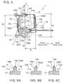
- FIG. 5 is a sectional view which is taken along line A-A in FIG. 4 .
- FIGS. 6A to 6C are schematic sectional views which illustrate sectional shapes of the protrusion portion 14.
- the protrusion portion 14 protrudes from the face 12a2 of the base portion 12a, and is bonded to the fin 13.
- the protrusion portion 14 can be provided between one fin 13 and another fin 13 which is close to the one fin 13.
- the protrusion portion 14 can be bonded to at least any one of the one fin 13 and another fin 13.
- the protrusion portion 14 is bonded to a base side of the fin 13.
- the protrusion portion 14 is bonded to the flange portion 12 in which the light emitting module 20 as a heat source is provided.
- the protrusion portion 14 also functions as a heat radiating fin.
- a position of a top face 14a of the protrusion portion 14 is located on the flange portion 12 side (base portion 12a side), rather than a position of a top face 13a of the fin 13. That is, a height of the protrusion portion 14 is set to be lower than a height of the fin 13.
- the protrusion portion 14 includes a face 14b1 (corresponding to an example of first face) which intersects the fin 13, and a face 14b2 (corresponding to an example of second face) which stands face to face with the face 14b1.
- At least any one of the face 14b1 and the face 14b2 is inclined so that a distance between the face 14b1 and the face 14b2 becomes gradually short toward the top face 14a of the protrusion portion 14.
- At least any one of the face 14b1 and the face 14b2 is an inclined face.
- the air flow direction 100 is influenced by an attaching form of the lighting device for vehicle 1, a circumstance in which the lighting device for vehicle 1 is attached, or the like.
- the protrusion portion 15 is provided inside the recessed portion 12c.
- a tip end of the protrusion portion 15 protrudes from the face 12a2 of the base portion 12a.
- the protrusion portion 15 is bonded to the fin 13.
- the protrusion portion 15 can be bonded to at least any one of the one fin 13 and another fin 13.
- the protrusion portion 15 is bonded to the base side of the fin 13.
- the protrusion portion 15 also functions as a heat transmission unit and a heat radiating fin.
- a position of a top face 15a of the protrusion portion 15 is located on the flange portion 12 side, rather than a position of the top face 13a of the fin 13.
- the position of the top face 15a of the protrusion portion 15 in the protruding direction (height direction) of the protrusion portion 15 can be set so as to be the same as the position of the top face 14a of the protrusion portion 14.
- the protrusion portion 15 includes a face 15b1 which intersects the fin 13, and a face 15b2 which stands face to face with the face 15b1.
- At least any one of the face 15b1 and the face 15b2 is inclined so that a distance between the face 15b1 and the face 15b2 becomes gradually short toward the top face 15a of the protrusion portion 15.
- At least any one of the face 15b1 and the face 15b2 is an inclined face.
- both the face 15b1 and the face 15b2 are inclined faces.
- the air flow direction 100 is influenced by an attaching form of the lighting device for vehicle 1, a circumstance in which the lighting device for vehicle 1 is attached, or the like.
- the protrusion portion 12b between the light emitting module 20 and the base portion 12a becomes a heat transmission unit.
- the maximum dimension (dimension of diameter when base portion 12a is columnar shape) A1 (mm) of the base portion 12a in a direction orthogonal to the center axis 1a of the lighting device for vehicle 1 (refer to FIG. 5 ), the maximum dimension (dimension of diameter when protrusion portion 12b is columnar shape) A2 (mm) of the protrusion portion 12b in a direction orthogonal to the center axis 1a of the lighting device for vehicle 1 (refer to FIG. 5 ), and the power W (watt) which is applied to the light emitting module 20 are involved with a heat radiating performance.
- the maximum dimension A2 of the protrusion portion 12b is regulated by a dimension, or the like, of an attaching hole which is provided in a lighting tool for vehicle.
- the power W which is applied to the light emitting module 20 is regulated by specifications or the number of the light emitting elements 22.
- the maximum dimension A1 of the base portion 12a has the greatest influence on an improvement of a heat radiating performance.
- heat conductivity of a heat conductive resin it is preferable to set heat conductivity of a heat conductive resin to 11 W/ (m•K) or less.
- the maximum dimension A1 of the base portion 12a is set to 40 mm or less, it is possible to improve a heat radiating performance, and realize light-weighting.
- Table 1 is a table for denoting an evaluation result related to (A1-A2)/W.
- Table 1 denotes a result which is obtained by acquiring a heat radiation amount and a weight of the socket 10 through a simulation, and determining whether a heat radiating performance and light-weighting are good or bad, using a predetermined threshold value.
- heat conductivity of a heat conductive resin is set to 7 W/(m•K) or more and 11 W/(m•K) or less.
- the power W which is applied to the light emitting module 20 is set to 1.0 W or more and 6.0 W or less.
- the maximum dimension A1 of the base portion 12a is set to 40 mm or less.
- an evaluation of (A1-A2)/W is performed by changing the maximum dimension A1 of the base portion 12a, and the maximum dimension A2 of the protrusion portion 12b.
- (A1-A2)/W is set to 1.0 (mm/W) or more and 6.5 (mm/W) or less, it is possible to improve a heat radiating performance, and realize light-weighting.
- the fin 13 functions as a heat radiating fin.
- heat conductivity of a heat conductive resin it is preferable to set heat conductivity of a heat conductive resin to 11 W/(m•K) or less.
- the distance B to the top face 13a of the fin 13 is set to 35 mm or less, it is possible to improve a heat radiating performance, and realize light-weighting.
- the protrusion portion 14 functions as a heat radiating fin.
- heat conductivity of a heat conductive resin it is preferable to set heat conductivity of a heat conductive resin to 11 W/(m•K) or less.
Landscapes
- Engineering & Computer Science (AREA)
- General Engineering & Computer Science (AREA)
- Physics & Mathematics (AREA)
- Microelectronics & Electronic Packaging (AREA)
- Optics & Photonics (AREA)
- Led Device Packages (AREA)
- Non-Portable Lighting Devices Or Systems Thereof (AREA)
- Arrangement Of Elements, Cooling, Sealing, Or The Like Of Lighting Devices (AREA)
- Mechanical Engineering (AREA)
Abstract
Description
- Embodiments described herein relate generally to a lighting device for vehicle.
- There is a lighting device for vehicle which is provided with a socket, and a light emitting module which includes a plurality of light emitting diodes (LED), and is provided in the socket.
- I n such a lighting device for vehicle, heat generated in the light emitting diode is mainly radiated to the outside through the socket. For this reason, the socket is formed of metal with high heat conductivity such as aluminum.
- Here, a lightweight lighting device for vehicle is desired.
- For this reason, as a material of the socket, a heat conductive resin containing a filler which is formed of carbon, or the like, is used.
- However, when a socket formed of a heat conductive resin is simply adopted, a heat radiating performance becomes lower than that of a socket formed of metal such as aluminum.
- For this reason, a technology in which a metallic member is provided between a light emitting module and a socket which is formed of a heat conductive resin in order to improve a heat radiating performance is proposed.
- However, when a metallic member is provided, it causes an increase in weight and manufacturing cost.
- Therefore, a development of a technology in which it is possible to improve the heat radiating performance of a socket itself which is formed of a heat conductive resin is desired.
-
-
FIG. 1 is a schematic perspective view which illustrates a lighting device for vehicle according to one embodiment. -
FIG. 2 is an exploded perspective view which schematically illustrates the lighting device for vehicle. -
FIG. 3 is a schematic plan view of a light emitting module. -
FIG. 4 is a schematic perspective view which illustrates protrusion portions. -
FIG. 5 is a sectional view which is taken along line A-A inFIG. 4 . -
FIGS. 6A to 6C are schematic sectional views which illustrate sectional shapes of the protrusion portion. - An exemplary embodiment according to one embodiment is a lighting device for vehicle which includes a socket including a base portion, and a first protrusion portion which protrudes from one face of the base portion; and a light emitting module which is provided at the first protrusion portion, and includes a light emitting element.
- The socket contains a heat conductive resin of which heat conductivity is 7 W/(m•K) or more and 11 W/(m•K) or less.
- When a maximum dimension of the base portion in a direction orthogonal to a center axis of the lighting device for vehicle is set to A1 (mm), a maximum dimension of the first protrusion portion in a direction orthogonal to the center axis is set to A2 (mm), and power which is applied to the light emitting module is set to W (watt), (A1-A2)/W becomes 1.0 (mm/W) or more and 6.5 (mm/W) or less.
- I n the lighting device for vehicle according to the embodiment, it is possible to improve a heat radiating performance, and realize light-weighting.
- In the device, the socket may further include a fin which is provided on a side opposite to a side of the base portion on which the first protrusion portion is provided.
- A distance from a face of the base portion on the side opposite to the side on which the first protrusion portion is provided to a top face of the fin may be set to 35 mm or less.
- In this manner, it is possible to increase a heat radiating area, and prevent the fin from being wastefully heavy.
- In the device, the maximum dimension A1 may be set to 40 mm or less.
- In this manner, it is possible to increase a heat radiating area, and prevent the base portion from being wastefully heavy.
- In the device, the power W may be set to 1.0 W or more and 6.0 W or less.
- In this manner, it is possible to suppress wasteful heating in the light emitting module.
- In the device, the socket may further include a second protrusion portion which is provided on a face of the base portion on the side opposite to the side on which the first protrusion portion is provided, and is bonded to the fin.
- A distance from the face of the base portion on the side opposite to the side on which the first protrusion portion is provided to a top face of the second protrusion portion may be set to 4 mm or less.
- In this manner, it is possible to cause air flow in the vicinity of the fin not to be disturbed. In addition, it is possible to increase a heat radiating area, and prevent the second protrusion portion from being wastefully heavy.
- Hereinafter, one embodiment will be exemplified while referring to drawings. In addition, in each figure, the same constituent elements will be given the same reference numerals, and detailed descriptions will be appropriately omitted.
-
FIG. 1 is a schematic perspective view which illustrates a lighting device forvehicle 1 according to the embodiment. -
FIG. 2 is an exploded perspective view which schematically illustrates the lighting device forvehicle 1. -
FIG. 3 is a schematic plan view of alight emitting module 20. - As illustrated in FI GS. 1 and 2, a
socket 10, thelight emitting module 20, apower feeding unit 30, and aconnector 40 are provided in the lighting device forvehicle 1. - An
accommodation unit 11, aflange portion 12, afin 13, a protrusion portion 14 (corresponding to an example of second protrusion portion), a protrusion portion 15 (corresponding to an example of third protrusion portion), and an attachingunit 16 are provided in thesocket 10. - The
accommodation unit 11 is formed in a cylindrical shape, and protrudes from aprotrusion portion 12b (corresponding to an example of first protrusion portion) of theflange portion 12. Thelight emitting module 20 is provided inside theaccommodation unit 11, and on theprotrusion portion 12b of theflange portion 12. I n addition, apower feeding terminal 31 of apower feeding unit 30 protrudes to the inside of theaccommodation unit 11. - The
flange portion 12 includes abase portion 12a, theprotrusion portion 12b, and arecessed portion 12c (refer toFIG. 5 ). - The
base portion 12a is formed in a disk shape. - The
protrusion portion 12b protrudes from one face of thebase portion 12a. Theprotrusion portion 12b is provided on a face 12a1 of thebase portion 12a. The face 12a1 of thebase portion 12a faces a front face side of the lighting device forvehicle 1. - The
light emitting module 20 which includes alight emitting element 22 is provided on theprotrusion portion 12b. - A face 12a2 of the
base portion 12a is provided in therecessed portion 12c (refer toFIG. 5 ). The face 12a2 of thebase portion 12a faces a rear face side of the lighting device forvehicle 1. - That is, the
recessed portion 12c is provided on a side opposite to a side on which thelight emitting module 20 is provided. - I n addition, the
fin 13, and aprotrusion portion 14 are provided on the face 12a2 of thebase portion 12a. - The fin 13 protrudes from the face 12a2 of the
base portion 12a. A plurality of thefins 13 are provided. The plurality offins 13 are formed in a plate shape, and function as heat radiating fins. - The
protrusion portion 14 protrudes from the face 12a2 of thebase portion 12a, and is bonded to thefin 13. - The
protrusion portion 15 is provided inside the recessedportion 12c, and a tip end thereof protrudes from the face 12a2 of thebase portion 12a. - That is, the
protrusion portion 15 is provided inside therecessed portion 12c, and protrudes from the face 12a2 of thebase portion 12a on a side opposite to the side on which thelight emitting module 20 is provided. - The
protrusion portion 15 is bonded to thefin 13. - I n addition, the
protrusion portion 12b, the recessedportion 12c, theprotrusion portion 14, and theprotrusion portion 15 will be described in detail later. - It is also possible to integrally mold the
accommodation unit 11, theflange portion 12, thefin 13, theprotrusion portion 14, and theprotrusion portion 15, and bond these elements using an adhesive, or the like. - However, when the
accommodation unit 11, theflange portion 12, thefin 13, theprotrusion portion 14, and theprotrusion portion 15 are integrally molded, it is possible to improve a heat radiating performance, and resistance against an external force, and to reduce a manufacturing cost. - The attaching
unit 16 is provided on a side wall of theaccommodation unit 11. The attachingunit 16 protrudes toward the outside of the lighting device forvehicle 1. - A plurality of the attaching
units 16 are provided. - The attaching
unit 16 is inserted into a groove portion which is provided in a lighting tool for vehicle when mounting the lighting device forvehicle 1 on the lighting tool for vehicle. In addition, the lighting device forvehicle 1 is held in the lighting tool for vehicle when rotating the lighting device forvehicle 1. - That is, the attaching
unit 16 is used as a twist-lock. - Here, when a current flows in the
light emitting element 22, acontrol element 23, or the like, heat is generated. - When a temperature of the
light emitting element 22 excessively increases due to the generated heat, there is a concern that a decrease in light flux, a disconnection ofwiring 25, a separation of thelight emitting element 22, or the like, may occur. - For this reason, it is necessary to efficiently radiate the generated heat to the outside of the lighting device for
vehicle 1. - I n this case, the generated heat is radiated to the outside mainly through the
socket 10. - When a material of the
socket 10 is metal with high heat conductivity such as aluminum, it is possible to efficiently radiate the generated heat to the outside of the lighting device forvehicle 1. - However, there is a problem in that the lighting device for
vehicle 1 becomes heavy since metal has high specific gravity. In contrast to this, when a material of thesocket 10 is a heat conductive resin, it is possible to make the lighting device forvehicle 1 lightweight. However, when adopting the heat conductive resin as a material of thesocket 10, a heat radiating performance decreases compared to a socket formed of metal. - In this case, when increasing an amount of filler contained in a heat conductive resin, heat conductivity can be increased, and accordingly, it is possible to suppress deterioration in heat radiating performance.
- However, when increasing an amount of filler contained in the heat conductive resin, there is a problem in that the heat conductive resin becomes fragile, and machining becomes difficult.
- For this reason, when considering a heat radiating performance and processability, it is preferable to set heat conductivity of the heat conductive resin to 7 W (m•K) or more and 11 W (m•K) or less.
- In addition, the heat conductive resin can be a resin in which filler formed of carbon with high heat conductivity, aluminum oxide, or the like, is mixed in a resin of, for example, polyethylene terephthalate (PET), nylon, or the like.
- As illustrated in
FIG. 3 , asubstrate 2, thelight emitting element 22, thecontrol element 23, thewiring 25, aframe portion 26, a sealingportion 27, ajoint portion 28, acontrol element 29, acover portion 51, ametal film 34, and acontrol element 52 are provided in thelight emitting module 20. - I n addition, a
base body 21, and awiring pattern 24 are provided on thesubstrate 2. - The
base body 21 is provided inside theaccommodation unit 11 of thesocket 10, and on theprotrusion portion 12b of theflange portion 12. - The
base body 21 is formed in a plate shape, and is provided with thewiring pattern 24 on the surface thereof. - The
base body 21 can be formed of, for example, ceramic of aluminum oxide, aluminum nitride, or the like. - In addition, the
base body 21 may have a single-layer structure, or a multi-layer structure. - The
wiring pattern 24 is provided at least on one surface of thebase body 21. - The
wiring pattern 24 can be provided on both faces of thebase body 21 ; however, it is preferable to provide the wiring pattern on one face of thebase body 21, in order to reduce a manufacturing cost. - An
input terminal 24a is provided in thewiring pattern 24. - A plurality of the
input terminals 24a are provided. Thepower feeding terminal 31 of thepower feeding unit 30 is electrically connected to theinput terminal 24a. For this reason, thelight emitting element 22 is electrically connected to thepower feeding unit 30 through thewiring pattern 24. - The
wiring pattern 24 can be formed of a material of which a main component is silver. Thewiring pattern 24 can be formed of, for example, silver, or a silver alloy. However, a material of thewiring pattern 24 is not limited to the material of which a main component is silver. It is also possible to form thewiring pattern 24 using, for example, a material of which a main component is copper, or the like. - It is possible to form the
wiring pattern 24 using, for example, a screen printing method, and a baking method. - A plurality of the
light emitting elements 22 are provided on thewiring pattern 24. - The
light emitting element 22 can include an electrode (not illustrated) on a face (top face) on a side opposite to the side on which the light emitting element is provided in thewiring pattern 24. In addition, an electrode (not illustrated) may be provided on a face (lower face) on a side on which the light emitting element is provided in thewiring pattern 24, and the face (top face) on the side opposite to the side on which the light emitting element is provided in thewiring pattern 24, and may be provided on only one face thereof. - An electrode (not illustrated) which is provided on the lower face of the
light emitting element 22 is electrically connected to amounting pad 24b which is provided in thewiring pattern 24 through a conductive thermosetting material such as silver paste. An electrode (not illustrated) which is provided on the top face of thelight emitting element 22 is electrically connected to awiring pad 24c which is provided in thewiring pattern 24 through thewiring 25. - The
light emitting element 22 can be set to, for example, a light emitting diode, an organic light emitting diode, a laser diode, or the like. - The top face of the
light emitting element 22 as a light emission surface of light faces the front face side of the lighting device forvehicle 1. Thelight emitting element 22 mainly emits light toward the front face side of the lighting device forvehicle 1. - The number, a size, an arrangement, or the like, of the
light emitting element 22 is not limited to exemplifications, and can be appropriately changed according to a size, a use, or the like, of the lighting device forvehicle 1. - The
control element 23 is provided on thewiring pattern 24. - The
control element 23 controls a current which flows in thelight emitting element 22. - Since there is a variation in forward voltage characteristics of the
light emitting element 22, when setting an application voltage between an anode terminal and a ground terminal to be constant, a variation occurs in brightness (light flux, luminance, intensity of light, illumination) of thelight emitting element 22. For this reason, a value of a current which flows in thelight emitting element 22 is set so as to be within a predetermined range using thecontrol element 23, so that brightness of thelight emitting element 22 is within a predetermined range. - The
control element 23 can be set to, for example, a resistor. Thecontrol element 23 can be set to, for example, a surface-mounted resistor, a resistor including a lead wire (metal oxide film resistor), a film-shaped resistor which is formed by using a screen printing method and a baking method, and the like. - In addition, the
control element 23 illustrated inFIG. 3 is a film-shaped resistor. - In addition, it is possible to set a value of a current which flows in the
light emitting element 22 to be within a predetermined range by changing a resistance value of thecontrol element 23. - For example, when the
control element 23 is a film-shaped resistor, an elimination portion (not illustrated) is formed, by eliminating a part of thecontrol element 23. In addition, a resistance value of thecontrol element 23 is changed by using a size, the number, or the like, of the elimination portion. In this case, when a part of thecontrol element 23 is eliminated, the resistance value increases. Eliminating of a part of thecontrol element 23 can be performed by radiating laser light to thecontrol element 23. - The number, a size, arrangements, or the like, of the
control element 23 is not limited to the exemplifications, and can be appropriately changed according to the number, specifications, or the like, of thelight emitting element 22. - The
wiring 25 electrically connects an electrode (not illustrated) which is provided on the top face of thelight emitting element 22 and thewiring pad 24c which is provided in thewiring pattern 24. - The
wiring 25 can be set to, for example, a wire of which a main component is gold. However, a material of thewiring 25 is not limited to the material of which a main component is gold. A material of thewiring 25 may be a material, for example, of which a main component is copper, aluminum, or the like. - The
wiring 25 is electrically connected to the electrode (not illustrated) provided on the top face of thelight emitting element 22, and thewiring pad 24c which is provided in thewiring pattern 24, using ultrasonic welding or heat welding, for example. Thewiring 25 can be electrically connected to the electrode (not illustrated) provided on the top face of thelight emitting element 22, and thewiring pad 24c which is provided in thewiring pattern 24 using a wire bonding method, for example. - The
frame portion 26 is provided on thebase body 21 so as to surround the plurality oflight emitting elements 22. Theframe portion 26 is formed in an annular shape, for example, and the plurality oflight emitting elements 22 are arranged at acenter portion 26a. - The
frame portion 26 can be formed of, for example, a resin of polybutylene terephthalate (PBT), polycarbonate (PC), or the like, or ceramic, or the like. - In addition, when a material of the
frame portion 26 is set to a resin, it is possible to improve reflectivity with respect to light emitted from thelight emitting element 22 by mixing particles of titanium oxide, or the like. - In addition, particles which are formed of a material with high reflectivity with respect to light emitted from the
light emitting element 22 may be mixed, without limiting to particles of titanium oxide. - In addition, the
frame portion 26 can be formed of a white resin, for example. - A
side wall face 26b of theframe portion 26 on thecenter portion 26a side is an inclined face. Part of light emitted from thelight emitting element 22 is reflected on theside wall face 26b of theframe portion 26, and is emitted toward the front face side of the lighting device forvehicle 1. - In addition, light which is part of light emitted toward the front face side of the lighting device for
vehicle 1 from thelight emitting element 22, and is totally reflected on a top face of the sealing portion 27 (interface between sealingportion 27 and ambient air) is reflected on theside wall face 26b of theframe portion 26 on thecenter portion 26a side, and is reemitted toward the front face side of the lighting device forvehicle 1. - That is, the
frame portion 26 has a function of regulating a formation range of the sealingportion 27, and functions as a reflector. In addition, a form of theframe portion 26 can be appropriately changed without being limited to exemplifications. - The sealing
portion 27 is provided at thecenter portion 26a of theframe portion 26. The sealingportion 27 is provided so as to cover the inside of theframe portion 26. That is, the sealingportion 27 is provided inside theframe portion 26, and covers thelight emitting element 22, thewiring 25, or the like. - The sealing
portion 27 is formed of a material with light transmittance. The sealingportion 27 can be formed of, for example, a silicone resin, or the like. - The sealing
portion 27 can be formed, for example, by filling thecenter portion 26a of theframe portion 26 with a resin. Filling of a resin can be performed, for example, by using a quantitative liquid ejecting device such as a dispenser. When a resin is filled in thecenter portion 26a of theframe portion 26, it is possible to suppress a mechanical contact from the outside with respect to thelight emitting element 22, thewiring pattern 24, thewiring 25, and the like, which are arranged at thecenter portion 26a of theframe portion 26. In addition, it is possible to prevent moisture, gas, or the like, from attaching to thelight emitting element 22, and thewiring pattern 24, thewiring 25, and the like, which are arranged at thecenter portion 26a of theframe portion 26. For this reason, it is possible to improve reliability of the lighting device forvehicle 1. - In addition, it is possible to contain a phosphor in the sealing
portion 27. The phosphor can be, for example, an yttrium-aluminum-garnet phosphor (YAG-based phosphor). - For example, when the
light emitting element 22 is a blue light emitting diode, and the phosphor is the YAG-based phosphor, the YAG-based phosphor is exited due to blue light which is emitted from thelight emitting element 22, and yellow fluorescence is radiated from the YAG-based phosphor. In addition, white light is emitted from the lighting device forvehicle 1 when the blue light and the yellow light are mixed together. In addition, a type of the phosphor, or a type of thelight emitting element 22 is not limited to exemplifications. The type of the phosphor, or the type of thelight emitting element 22 can be appropriately changed so as to obtain a desired luminescent color according to a use, or the like, of the lighting device forvehicle 1. - The
joint portion 28 joints theframe portion 26 and thebase body 21. - The
joint portion 28 is formed in a film shape, and is provided between theframe portion 26 and thebase body 21. - The
joint portion 28 can be formed by hardening a silicone-based adhesive or an epoxy-based adhesive, for example. - The
control element 29 is provided on thewiring pattern 24 through asoldering portion 33. That is, thecontrol element 29 is soldered on thewiring pattern 24. - The
control element 29 is provided so that a reverse voltage is not applied to thelight emitting element 22, and a pulse noise from an opposite direction is not applied to thelight emitting element 22. - The
control element 29 can be set to a diode, for example. Thecontrol element 29 can be set to, for example, a surface-mounted diode, a diode including a lead wire, or the like. - The
control element 29 illustrated inFIG. 3 is the surface-mounted diode. - The
control element 52 is provided on thewiring pattern 24. - The
control element 52 is provided in order to detect a disconnection of the light emitting diode, prevent erroneous lighting, or the like. Thecontrol element 52 is a pull-down resistor. - The
control element 52 can be set to a film-shaped resistor which is formed by using a screen printing method and a baking method. - The
control element 52 can be set to a film-shaped resistor which is formed of ruthenium oxide, for example. - The
cover portion 51 is provided so as to cover a part of thewiring pattern 24, thecontrol element 23 as the film-shaped resistor, and thecontrol element 52 as the film-shaped resistor. - In addition, the
cover portion 51 is not provided in a region in which thecontrol element 29 and thelight emitting element 22 are provided, a region in which thewiring 25 is connected, and a region in which thepower feeding terminal 31 is connected. - For example, the
cover portion 51 does not cover aregion 35 in which thecontrol element 29 is soldered. - The
cover portion 51 is provided so as to prevent moisture, gas, or the like, from coming into contact with thewiring pattern 24, thecontrol element 23, and thecontrol element 52, and to secure electric insulation. A glass material can be contained in thecover portion 51. - The
metal film 34 is provided in theregion 35 in which soldering is performed, and covers thewiring pattern 24. As described above, thewiring pattern 24 is formed of, for example, a material of which a main component is silver. For this reason, there is a case in which migration occurs due to an electrical connection under a high humidity condition. For example, there is a case in which short circuit may occur betweensoldering portions 33 which stand face to face with each other, or the like. - For this reason, the
metal film 34 for covering thewiring pattern 24 is provided in order to suppress migration, or improve solder wettability. - In addition, when the
wiring pattern 24 is formed of a material of which a main component is copper, for example, oxidization or a reaction with sulfur becomes quick under a high temperature condition, or under an atmosphere with many sulfur components, and there is a case in which solder wettability deteriorates. For this reason, also when thewiring pattern 24 is formed of a material of which a main component is copper, it is preferable to provide themetal film 34 which covers thewiring pattern 24. - The
metal film 34 can be set to a laminated film including at least a film formed of nickel, and a film formed of gold. Themetal film 34 can be set to a laminated film in which the film formed of nickel, and the film formed of gold are laminated in this order, and a laminated film in which the film formed of nickel, a film formed of palladium, and the film formed of gold are laminated in this order, for example. - The
metal film 34 can be formed in theregion 35 in which soldering is performed, using an electroless plating method, for example. - A plurality of the
power feeding terminals 31 are provided in thepower feeding unit 30. - The plurality of
power feeding terminals 31 extend inside theaccommodation unit 11 and theflange portion 12. One end portion of the plurality ofpower feeding terminals 31 protrudes from theprotrusion portion 12b of theflange portion 12, and is electrically connected to theinput terminal 24a of thewiring pattern 24. The other end portion of the plurality ofpower feeding terminals 31 is exposed from thesocket 10 on a rear face side of the lighting device forvehicle 1. - In addition, the number, an arrangement, a form, or the like, of the
power feeding terminal 31 is not limited to exemplifications, and can be appropriately changed. - In addition, the
power feeding unit 30 can include a substrate (not illustrated), or a circuit component such as a capacitor, or a resistor. In addition, the substrate (not illustrated), or the circuit component can be provided, for example, inside theaccommodation unit 11, inside theflange portion 12, or the like. - The
connector 40 is fitted into an end portion of the plurality ofpower feeding terminals 31 which are exposed from thesocket 10. - A power supply (not illustrated), or the like, is electrically connected to the
connector 40. - For this reason, the power supply (not illustrated), or the like, and the
light emitting element 22 are electrically connected when theconnector 40 is fitted into the end portion of thepower feeding terminal 31. - The
connector 40 can be bonded to elements on thesocket 10 side using, for example, an adhesive, or the like. - Subsequently, a heat radiating performance of the lighting device for
vehicle 1 will be further described. - First, the
protrusion portion 12b, the recessedportion 12c, theprotrusion portion 14, and theprotrusion portion 15 will be described. - As described above, when increasing an amount of filler contained in a heat conductive resin, it is possible to improve a heat radiating performance; however, the heat conductive resin becomes fragile, and resistance against an external force (mechanical strength) decreases.
- In addition, the
fin 13 is formed in a plate shape in order to cause air to easily flow betweenfins 13. In addition, when thefin 13 and theflange portion 12 are integrally molded, it is necessary to make a thickness of thefin 13 thin to some extent in order to suppress a sink mark (recession, deformation) at a time of molding. For this reason, when thefin 13 is molded by using a heat conductive resin, resistance against an external force of thefin 13 decreases, and a fracture, or the like, easily occurs at a bonding portion between thefin 13 and the flange portion 12 (base of fin 13), or the like. - Therefore, according to the embodiment, the
protrusion portion 14 which is bonded to thefin 13 and theflange portion 12 is provided. - In addition, as described above, the
light emitting module 20 is provided inside theaccommodation unit 11. - For this reason, light emitted from the
light emitting element 22 is easily blocked by theaccommodation unit 11, or the attachingunit 16 which is provided on the side wall of theaccommodation unit 11. - I n this case, when an attaching position of the
light emitting module 20 is set to be close to the front face side of the lighting device forvehicle 1, it is possible to prevent light emitted from thelight emitting element 22 from being blocked by theaccommodation unit 11 or the attachingunit 16. - For this reason, the
protrusion portion 12b which protrudes toward the front face side of the lighting device forvehicle 1 from thebase portion 12a is provided, and thelight emitting module 20 is provided in theprotrusion portion 12b. That is, the attaching position of thelight emitting module 20 is set to be close to the front face side of the lighting device forvehicle 1, by providing theprotrusion portion 12b. - However, when the
protrusion portion 12b is provided, theflange portion 12 becomes thick as much as theprotrusion portion 12b, and it causes an increase in weight, in material cost, or the like. - For this reason, a weight or a material cost is suppressed by providing the recessed
portion 12c on the face 12a2 of thebase portion 12a. The recessedportion 12c is open to the face 12a2 of thebase portion 12a. - However, since air rarely flows inside the recessed
portion 12c, there is a concern that heat may stay inside the recessedportion 12c, and a heat radiating performance may deteriorate. - Therefore, according to the embodiment, the
protrusion portion 15 which is bonded to thefin 13 is provided inside the recessedportion 12c. -
FIG. 4 is a schematic perspective view which illustrates theprotrusion portions - In addition,
FIG. 4 is a figure in which the lighting device forvehicle 1 is viewed from the rear face side (side opposite to side on which light emittingmodule 20 is provided). -
FIG. 5 is a sectional view which is taken along line A-A inFIG. 4 . -
FIGS. 6A to 6C are schematic sectional views which illustrate sectional shapes of theprotrusion portion 14. - As illustrated in FI GS. 4 and 5, the
protrusion portion 14 protrudes from the face 12a2 of thebase portion 12a, and is bonded to thefin 13. - I n this case, the
protrusion portion 14 can be provided between onefin 13 and anotherfin 13 which is close to the onefin 13. - I n addition, the
protrusion portion 14 can be bonded to at least any one of the onefin 13 and anotherfin 13. - That is, the
protrusion portion 14 is bonded to a base side of thefin 13. - For this reason, it is possible to improve resistance against an external force of the
fin 13. - I n this case, a direction in which the
fin 13 extends, and a direction in which theprotrusion portion 14 extends can be crossed. In this manner, it is possible to further improve resistance against an external force of thefin 13. - I n addition, the
protrusion portion 14 is bonded to theflange portion 12 in which thelight emitting module 20 as a heat source is provided. - For this reason, the
protrusion portion 14 also functions as a heat radiating fin. - When the
protrusion portion 14 is provided, it is possible to improve a heat radiating performance. - Here, air flows in the vicinity of the
fin 13 due to natural convection, or the like. For this reason, when air flow is disturbed by theprotrusion portion 14, there is a concern that an improvement of a heat radiating performance may not be obtained. - I n this case, when the
protrusion portion 14 is provided between thefins 13, air flow between thefins 13 is easily disturbed. - Therefore, a position of a
top face 14a of theprotrusion portion 14 is located on theflange portion 12 side (base portion 12a side), rather than a position of atop face 13a of thefin 13. That is, a height of theprotrusion portion 14 is set to be lower than a height of thefin 13. - In this manner, it is possible to prevent air flow in the vicinity of the
fin 13 from being disturbed even when theprotrusion portion 14 is provided. - I n addition, as illustrated in
FIG. 5 , theprotrusion portion 14 includes a face 14b1 (corresponding to an example of first face) which intersects thefin 13, and a face 14b2 (corresponding to an example of second face) which stands face to face with the face 14b1. - At least any one of the face 14b1 and the face 14b2 is inclined so that a distance between the face 14b1 and the face 14b2 becomes gradually short toward the
top face 14a of theprotrusion portion 14. - That is, at least any one of the face 14b1 and the face 14b2 is an inclined face.
- I n this case, as illustrated in
FIG. 6A , it is possible to set both the face 14b1 and the face 14b2 to inclined faces. - When both the face 14b1 and the face 14b2 are set to inclined faces, inclining directions are set to be opposite to each other.
- I n addition, as illustrated in FI GS. 6B and 6C, it is also possible to set the face 14b1 or the face 14b2 to an inclined face.
- In addition, when a plurality of the
protrusion portions 14 are provided, it is possible to set respective faces 14b1 of the plurality ofprotrusion portions 14 so as to be inclined in the same direction. It is possible to set respective faces 14b2 of the plurality ofprotrusion portions 14 so as to be inclined in the same direction. - When an inclined face is provided, it is possible to prevent turbulence from occurring in air flow.
- For this reason, a heat radiating performance can be improved, since it is possible to make air flow smooth.
- I n this case, as illustrated in FI GS. 6B and 6C, it is possible to set a face on the upstream side in an
air flow direction 100 to an inclined face. - I n addition, the
air flow direction 100 is influenced by an attaching form of the lighting device forvehicle 1, a circumstance in which the lighting device forvehicle 1 is attached, or the like. - For this reason, as illustrated in
FIG. 6A , when two faces which stand face to face with each other (faces 14b1 and 14b2) are set to inclined faces, and inclining directions are set to be opposite to each other, even when it is not possible to know theair flow direction 100 in advance, or theair flow direction 100 is changed, it is possible to correspond to the case. - I n addition, as illustrated in FI GS. 4 and 5, the
protrusion portion 15 is provided inside the recessedportion 12c. - I n addition, a tip end of the
protrusion portion 15 protrudes from the face 12a2 of thebase portion 12a. Theprotrusion portion 15 is bonded to thefin 13. - I n this case, it is possible to provide the
protrusion portion 15 between onefin 13 and anotherfin 13 which is close to the onefin 13. - I n addition, the
protrusion portion 15 can be bonded to at least any one of the onefin 13 and anotherfin 13. - That is, the
protrusion portion 15 is bonded to the base side of thefin 13. - For this reason, it is possible to improve resistance against an external force of the
fin 13. - I n this case, a direction in which the
fin 13 extends, and a direction in which theprotrusion portion 15 extends can be crossed. In this manner, it is possible to further improve resistance against an external force of thefin 13. - As described above, since air rarely flows inside the recessed
portion 12c, heat easily stays inside the recessedportion 12c. - I n this case, when the
protrusion portion 15 is provided inside the recessedportion 12c, and theprotrusion portion 15 is bonded to thefin 13, it is possible to release heat in the inside of the recessedportion 12c to thefin 13. - In this manner, the
protrusion portion 15 also functions as a heat transmission unit and a heat radiating fin. - For this reason, when the
protrusion portion 15 is provided, it is possible to improve a heat radiating performance since heat in the inside of the recessedportion 12c can be released. - In addition, similarly to the above described
protrusion portion 14, a position of atop face 15a of theprotrusion portion 15 is located on theflange portion 12 side, rather than a position of thetop face 13a of thefin 13. - In this manner, it is possible to prevent air flow in the vicinity of the
fin 13 from being disturbed, even when theprotrusion portion 15 is provided. - I n this case, the position of the
top face 15a of theprotrusion portion 15 in the protruding direction (height direction) of theprotrusion portion 15 can be set so as to be the same as the position of thetop face 14a of theprotrusion portion 14. - In this manner, it is possible to prevent turbulence from occurring in air flow.
- For this reason, a heat radiating performance can be further improved, since it is possible to make air flow smooth.
- I n addition, as illustrated in
FIG. 5 , theprotrusion portion 15 includes a face 15b1 which intersects thefin 13, and a face 15b2 which stands face to face with the face 15b1. - At least any one of the face 15b1 and the face 15b2 is inclined so that a distance between the face 15b1 and the face 15b2 becomes gradually short toward the
top face 15a of theprotrusion portion 15. - That is, at least any one of the face 15b1 and the face 15b2 is an inclined face.
- In addition, similarly to the
protrusion portion 14 which is illustrated inFIG. 6A , it is possible to set both the face 15b1 and the face 15b2 to inclined faces. - When both the face 15b1 and the face 15b2 are set to inclined faces, inclining directions are set to be opposite to each other.
- In addition, similarly to the
protrusion portions 14 which are illustrated in FI GS. 6B and 6C, it is also possible to set the face 15b1 or the face 15b2 to an inclined face. - In addition, when a plurality of the
protrusion portions 15 are provided, it is possible to set respective faces 15b1 of the plurality ofprotrusion portions 15 so as to be inclined in the same direction. It is possible to set respective faces 15b2 of the plurality ofprotrusion portions 15 so as to be inclined in the same direction. - When an inclined face is provided, it is possible to prevent turbulence from occurring in air flow.
- For this reason, a heat radiating performance can be improved, since it is possible to make air flow smooth.
- In this case, similarly to the
protrusion portions 14 which are illustrated in FI GS. 6B and 6C, it is possible to set a face on the upstream side in theair flow direction 100 to an inclined face. - I n addition, the
air flow direction 100 is influenced by an attaching form of the lighting device forvehicle 1, a circumstance in which the lighting device forvehicle 1 is attached, or the like. - For this reason, similarly to the
protrusion portion 14 which is illustrated inFIG. 6A , when two faces which stand face to face with each other (faces 15b1 and 15b2) are set to inclined faces, and inclining directions are set to be opposite to each other, even when it is not possible to know theair flow direction 100 in advance, or theair flow direction 100 is changed, it is possible to correspond to the case. - Subsequently, the
base portion 12a, theprotrusion portion 12b, thefin 13, and theprotrusion portion 14 will be further described. - First, a heat radiating performance of the
base portion 12a and theprotrusion portion 12b will be described. - According to a knowledge which the invertors obtained, most of heat generated in the
light emitting element 22, or the like, is radiated to the outside from thebase portion 12a of theflange portion 12 which is close to thelight emitting module 20 as the heat source, and comes into contact with a lighting tool for vehicle, or the like. - I n addition, the
protrusion portion 12b between the light emittingmodule 20 and thebase portion 12a becomes a heat transmission unit. - In addition, when power W which is applied to the
light emitting module 20 increases, a heating value which is generated increases. - For this reason, the maximum dimension (dimension of diameter when
base portion 12a is columnar shape) A1 (mm) of thebase portion 12a in a direction orthogonal to thecenter axis 1a of the lighting device for vehicle 1 (refer toFIG. 5 ), the maximum dimension (dimension of diameter whenprotrusion portion 12b is columnar shape) A2 (mm) of theprotrusion portion 12b in a direction orthogonal to thecenter axis 1a of the lighting device for vehicle 1 (refer toFIG. 5 ), and the power W (watt) which is applied to thelight emitting module 20 are involved with a heat radiating performance. - According to a knowledge which the invertors obtained, when (A1-A2)/W is set to a predetermined value or more, it is possible to improve a heat radiating performance.
- In this case, the maximum dimension A2 of the
protrusion portion 12b is regulated by a dimension, or the like, of an attaching hole which is provided in a lighting tool for vehicle. In addition, the power W which is applied to thelight emitting module 20 is regulated by specifications or the number of thelight emitting elements 22. - For this reason, virtually, the maximum dimension A1 of the
base portion 12a has the greatest influence on an improvement of a heat radiating performance. - That is, when the maximum dimension A1 of the
base portion 12a is set to be large, it is possible to improve a heat radiating performance. - However, as described above, it is preferable to set heat conductivity of a heat conductive resin to 11 W/ (m•K) or less.
- For this reason, heat which is transmitted decreases, and there is a small temperature rise, when being far from the
light emitting module 20 as the heat source. - That is, even when the maximum dimension A1 of the
base portion 12a is set to be large more than necessary, since a temperature in a peripheral edge region of thebase portion 12a is not changed much, an improvement of a heat radiating performance is not expected. - Meanwhile, when the maximum dimension A1 of the
base portion 12a is set to be excessively large, there is a concern that light-weighting of the lighting device forvehicle 1 may not be realized. - According to a knowledge which the inventors obtained, when the maximum dimension A1 of the
base portion 12a is set to 40 mm or less, it is possible to improve a heat radiating performance, and realize light-weighting. - Table 1 is a table for denoting an evaluation result related to (A1-A2)/W.
Table 1 (A1-A2)/W HEAT RADIATING PERFORMANCE LIGHT-WEIGHTING 0 X ○ 1.0 ○ ○ 2.0 ○ ○ 3.0 ○ ○ 4.0 ○ ○ 5.0 ○ ○ 6.0 ○ ○ 6.5 ○ ○ 7.0 ○ X 8.0 ○ X - In addition, Table 1 denotes a result which is obtained by acquiring a heat radiation amount and a weight of the
socket 10 through a simulation, and determining whether a heat radiating performance and light-weighting are good or bad, using a predetermined threshold value. - I n this case, heat conductivity of a heat conductive resin is set to 7 W/(m•K) or more and 11 W/(m•K) or less.
- The power W which is applied to the
light emitting module 20 is set to 1.0 W or more and 6.0 W or less. - The maximum dimension A1 of the
base portion 12a is set to 40 mm or less. - In addition, an evaluation of (A1-A2)/W is performed by changing the maximum dimension A1 of the
base portion 12a, and the maximum dimension A2 of theprotrusion portion 12b. - I n addition, (A1-A2)/W=0 is obtained when A1 = A2.
- As is understood from the Table 1, when (A1-A2)/W is set to 1.0 (mm/W) or more and 6.5 (mm/W) or less, it is possible to improve a heat radiating performance, and realize light-weighting.
- In addition, when heat conductivity of a heat conductive resin is 7 W/(m•K) or more and 11 W/(m•K) or less, there is no change in an optimal range of (A1-A2)/W.
- Subsequently, a heat radiating performance of the
fin 13 will be described. - As described above, the
fin 13 functions as a heat radiating fin. - For this reason, when a distance B (refer to
FIG. 5 ) from the face 12a2 of thebase portion 12a on the side opposite to the side on which theprotrusion portion 12b is provided to thetop face 13a of thefin 13 is set to be large, it is possible to improve a heat radiating performance. - However, as described above, it is preferable to set heat conductivity of a heat conductive resin to 11 W/(m•K) or less.
- For this reason, heat which is transmitted decreases, and there is a small temperature rise, when being far from the
light emitting module 20 as the heat source. - That is, even when the distance B to the
top face 13a of the fin 13 (protruding length of fin 13) is set to be large more than necessary, since a temperature in a tip end region of thefin 13 is not changed much, an improvement of a heat radiating performance is not expected. - Meanwhile, when the distance B to the
top face 13a of thefin 13 is set to be excessively large, there is a concern that light-weighting of the lighting device forvehicle 1 may not be realized. - According to a knowledge which the inventors obtained, when the distance B to the
top face 13a of thefin 13 is set to 35 mm or less, it is possible to improve a heat radiating performance, and realize light-weighting. - Subsequently, a heat radiating performance of the
protrusion portion 14 will be described. - As described above, the
protrusion portion 14 functions as a heat radiating fin. - For this reason, when a distance C (mm) from the face 12a2 of the
base portion 12a on the side opposite to the side on which theprotrusion portion 12b is provided to thetop face 14a of the protrusion portion 14 (refer toFIG. 5 ) is set to be large, it is possible to improve a heat radiating performance. - However, as described above, it is preferable to set heat conductivity of a heat conductive resin to 11 W/(m•K) or less.
- For this reason, heat which is transmitted decreases, and there is a small temperature rise, when being far from the
light emitting module 20 as the heat source. - That is, even when the distance C (protruding length of protrusion portion 14) to the
top face 14a of theprotrusion portion 14 is set to be large more than necessary, since a temperature in a tip end region of theprotrusion portion 14 is not changed much, an improvement of a heat radiating performance is not expected. - In addition, as described above, the larger the distance C to the
top face 14a of theprotrusion portion 14 is, air flow in the vicinity of thefin 13 is disturbed. - For this reason, when the distance C to the
top face 14a of theprotrusion portion 14 is excessively large, there is a concern that a heat radiating performance may further deteriorate. - I n addition, when the distance C to the
top face 14a of theprotrusion portion 14 is excessively large, there is a concern that light-weighting of the lighting device forvehicle 1 may not be realized. - According to a knowledge which the inventors obtained, when the distance C to the
top face 14a of theprotrusion portion 14 is set to 4 mm or less, it is possible to improve a heat radiating performance, and realize light-weighting. - While certain embodiments have been described, these embodiments have been presented by way of example only, and are not intended to limit the scope of the inventions. Indeed, the novel embodiments described herein may be embodied in a variety of other forms; furthermore, various omissions, substitutions and changes in the form of the embodiments described herein may be made without departing from the spirit of the inventions. The accompanying claims and their equivalents are intended to cover such forms or modifications as would fall within the scope and spirit of the inventions. Moreover, above-mentioned embodiments can be combined mutually and can be carried out.
Claims (5)
- A lighting device for vehicle (1) comprising:a socket (10) including a base portion (12a), and a first protrusion portion (12b) which protrudes from one face of the base portion (12a); anda light emitting module (20) which is provided at the first protrusion portion (12b), and includes a light emitting element (22),wherein the socket (10) contains a heat conductive resin of which heat conductivity is 7 W/(m•K) or more and 11 W/(m•K) or less, and when a maximum dimension of the base portion (12a) in a direction orthogonal to a center axis (1a) of the lighting device for vehicle (1) is set to A1 (mm), a maximum dimension of the first protrusion portion (12b) in a direction orthogonal to the center axis (1a) is set to A2 (mm), and power which is applied to the light emitting module (20) is set to W (watt), (A1-A2)/W becomes 1.0 (mm/W) or more and 6.5 (mm/W) or less.
- The device (1) according to claim 1,
wherein the socket (10) further includes a fin (13) which is provided on a side opposite to a side of the base portion (12a) on which the first protrusion portion (12b) is provided, and a distance from a face (12a2) of the base portion (12a) on the side opposite to the side on which the first protrusion portion (12b) is provided to a top face (13a) of the fin (13) is set to 35 mm or less. - The device (1) according to claim 1 or 2,
wherein the maximum dimension A1 is set to 40 mm or less. - The device (1) according to any one of claims 1 to 3,
wherein the power W is set to 1.0 W or more and 6.0 W or less. - The device (1) according to any one of claims 2 to 4,
wherein the socket (10) further includes a second protrusion portion (14) which is provided on a face (12a2) of the base portion (12a) on the side opposite to the side on which the first protrusion portion (12b) is provided, and is bonded to the fin (13), and a distance from the face (12a2) of the base portion (12a) on the side opposite to the side on which the first protrusion portion (12b) is provided to a top face (14a) of the second protrusion portion is set to 4 mm or less.
Applications Claiming Priority (1)
| Application Number | Priority Date | Filing Date | Title |
|---|---|---|---|
| JP2015146501A JP6508468B2 (en) | 2015-07-24 | 2015-07-24 | Vehicle lighting device and vehicle lighting device |
Publications (2)
| Publication Number | Publication Date |
|---|---|
| EP3121511A1 true EP3121511A1 (en) | 2017-01-25 |
| EP3121511B1 EP3121511B1 (en) | 2019-05-01 |
Family
ID=56120203
Family Applications (1)
| Application Number | Title | Priority Date | Filing Date |
|---|---|---|---|
| EP16178938.3A Active EP3121511B1 (en) | 2015-07-24 | 2016-07-12 | Lighting device for vehicle |
Country Status (4)
| Country | Link |
|---|---|
| US (1) | US20170023201A1 (en) |
| EP (1) | EP3121511B1 (en) |
| JP (1) | JP6508468B2 (en) |
| CN (1) | CN205807199U (en) |
Cited By (2)
| Publication number | Priority date | Publication date | Assignee | Title |
|---|---|---|---|---|
| EP3444526A1 (en) * | 2017-08-18 | 2019-02-20 | Toshiba Lighting & Technology Corporation | Lighting device for vehicles and lighting tool for vehicles |
| EP3913279A1 (en) * | 2020-05-20 | 2021-11-24 | Toshiba Lighting & Technology Corporation | Vehicle luminaire and vehicle lighting tool |
Families Citing this family (8)
| Publication number | Priority date | Publication date | Assignee | Title |
|---|---|---|---|---|
| JP6233979B2 (en) * | 2015-07-03 | 2017-11-22 | 本田技研工業株式会社 | Light source unit and vehicle room light |
| FR3053762B1 (en) * | 2016-07-07 | 2020-08-28 | Valeo Iluminacion Sa | LIGHT MODULE FOR MOTOR VEHICLES |
| JP6722402B2 (en) | 2016-08-19 | 2020-07-15 | 東芝ライテック株式会社 | Vehicle lighting device and vehicle lamp |
| JP6724709B2 (en) * | 2016-10-13 | 2020-07-15 | 東芝ライテック株式会社 | Vehicle lighting device and vehicle lamp |
| JP6969328B2 (en) * | 2017-11-30 | 2021-11-24 | 東芝ライテック株式会社 | Vehicle lighting equipment and vehicle lighting equipment |
| JP6911003B2 (en) * | 2018-12-14 | 2021-07-28 | Tdk株式会社 | Method of manufacturing element array and method of removing specific element |
| US11168879B2 (en) * | 2020-02-28 | 2021-11-09 | Omachron Intellectual Property Inc. | Light source |
| EP4336576B1 (en) * | 2022-09-09 | 2025-04-30 | ZKW Group GmbH | Lighting means for a motor vehicle headlight |
Citations (6)
| Publication number | Priority date | Publication date | Assignee | Title |
|---|---|---|---|---|
| US20080117647A1 (en) * | 2004-12-22 | 2008-05-22 | Patent-Treuhand-Gesellschaft Fur Elektrische Gluhlampen Mbh | Lighting Device Comprising at Least One Light-Emitting Diode and Vehicle Headlight |
| US20080153959A1 (en) * | 2006-12-20 | 2008-06-26 | General Electric Company | Thermally Conducting and Electrically Insulating Moldable Compositions and Methods of Manufacture Thereof |
| WO2008119392A1 (en) * | 2007-04-03 | 2008-10-09 | Osram Gesellschaft mit beschränkter Haftung | Semiconductor light module |
| WO2009153031A1 (en) * | 2008-06-18 | 2009-12-23 | Phoenix Contact Gmbh & Co. Kg | Illumination element having a plastic support |
| US20110095690A1 (en) * | 2009-10-22 | 2011-04-28 | Thermal Solution Resources, Llc | Overmolded LED Light Assembly and Method of Manufacture |
| WO2012164506A1 (en) * | 2011-05-31 | 2012-12-06 | Sabic Innovative Plastics Ip B.V. | Led plastic heat sink and method for making and using the same |
Family Cites Families (35)
| Publication number | Priority date | Publication date | Assignee | Title |
|---|---|---|---|---|
| US4715438A (en) * | 1986-06-30 | 1987-12-29 | Unisys Corporation | Staggered radial-fin heat sink device for integrated circuit package |
| JPH09129790A (en) * | 1995-11-07 | 1997-05-16 | Toshiba Corp | Heat sink device |
| US5947588A (en) * | 1997-10-06 | 1999-09-07 | Grand General Accessories Manufacturing Inc. | Light fixture with an LED light bulb having a conventional connection post |
| CN1148628C (en) * | 2000-05-10 | 2004-05-05 | 张玉媛 | Heat radiator |
| US6404634B1 (en) * | 2000-12-06 | 2002-06-11 | Hewlett-Packard Company | Single piece heat sink for computer chip |
| US6418020B1 (en) * | 2001-03-30 | 2002-07-09 | Advanced Thermal Technologies | Heat dissipation device with ribbed fin plates |
| US6845812B2 (en) * | 2002-12-20 | 2005-01-25 | Motorola, Inc. | Heatsink with multiple, selectable fin densities |
| US7300173B2 (en) * | 2004-04-08 | 2007-11-27 | Technology Assessment Group, Inc. | Replacement illumination device for a miniature flashlight bulb |
| JP2006049726A (en) * | 2004-08-06 | 2006-02-16 | Pia Kk | LED lamp |
| DE102006019310A1 (en) * | 2006-04-26 | 2007-10-31 | Robert Bosch Gmbh | Heat sink for the controller of an electric machine |
| US7712926B2 (en) * | 2006-08-17 | 2010-05-11 | Koninklijke Philips Electronics N.V. | Luminaire comprising adjustable light modules |
| CN101457880B (en) * | 2007-12-14 | 2010-09-29 | 富准精密工业(深圳)有限公司 | LED embedding lamp |
| JP5537777B2 (en) * | 2008-02-08 | 2014-07-02 | 日本モレックス株式会社 | Heat sink, cooling module and coolable electronic board |
| CN101977976B (en) * | 2008-03-20 | 2014-08-27 | 帝斯曼知识产权资产管理有限公司 | Heatsinks of thermally conductive plastic materials |
| US7905639B2 (en) * | 2008-05-28 | 2011-03-15 | Osram Sylvania Inc. | Side-loaded light emitting diode module for automotive rear combination lamps |
| US20090321045A1 (en) * | 2008-06-30 | 2009-12-31 | Alcatel-Lucent Technologies Inc. | Monolithic structurally complex heat sink designs |
| US8596837B1 (en) * | 2009-07-21 | 2013-12-03 | Cooper Technologies Company | Systems, methods, and devices providing a quick-release mechanism for a modular LED light engine |
| JP5409217B2 (en) * | 2009-09-07 | 2014-02-05 | 株式会社小糸製作所 | Vehicle lighting |
| CN102052576A (en) * | 2009-10-29 | 2011-05-11 | 扬光绿能股份有限公司 | lighting device |
| WO2011141846A2 (en) * | 2010-05-11 | 2011-11-17 | Koninklijke Philips Electronics N.V. | Lighting module |
| US8282249B2 (en) * | 2010-08-20 | 2012-10-09 | Siltek Electronic (Guangzhou) Co., Ltd. | Luminaire |
| CN202302782U (en) * | 2011-01-04 | 2012-07-04 | 中国灯饰工程有限公司 | LED lighting assembly with detachable power module |
| US8746915B2 (en) * | 2011-07-29 | 2014-06-10 | Cree, Inc. | Light emitting die (LED) lamps, heat sinks and related methods |
| US20140192537A1 (en) * | 2011-08-23 | 2014-07-10 | Samsung Electronics Co., Ltd. | Heat sink and lighting apparatus having same |
| JP2013089718A (en) * | 2011-10-17 | 2013-05-13 | Kaneka Corp | Heat sink with highly heat-conducting resin, and led light source |
| KR20130068528A (en) * | 2011-12-15 | 2013-06-26 | 삼성전자주식회사 | Light emitting device lamp |
| US9091426B2 (en) * | 2012-03-29 | 2015-07-28 | Abl Ip Holding Llc | Light assembly |
| JP5849831B2 (en) * | 2012-03-30 | 2016-02-03 | ブラザー工業株式会社 | Recording device |
| EP2841845A1 (en) * | 2012-04-26 | 2015-03-04 | Panasonic Intellectual Property Management Co., Ltd. | Lamp and lighting apparatus |
| US20140022800A1 (en) * | 2012-07-20 | 2014-01-23 | Tai-Her Yang | Cup-shaped heat dissipater having heat conductive rib therein and applied in electric luminous body |
| US9739543B2 (en) * | 2013-02-06 | 2017-08-22 | Te Connectivity Corporation | Heat sink |
| US9159642B2 (en) * | 2013-04-02 | 2015-10-13 | Gerald Ho Kim | Silicon-based heat dissipation device for heat-generating devices |
| JP6160858B2 (en) * | 2013-04-19 | 2017-07-12 | 東芝ライテック株式会社 | Lighting device and lamp |
| JP6217962B2 (en) * | 2013-05-09 | 2017-10-25 | 東芝ライテック株式会社 | VEHICLE LIGHTING DEVICE AND VEHICLE LIGHT |
| CN105283709A (en) * | 2013-05-29 | 2016-01-27 | 松下知识产权经营株式会社 | LED unit |
-
2015
- 2015-07-24 JP JP2015146501A patent/JP6508468B2/en active Active
-
2016
- 2016-07-12 US US15/207,786 patent/US20170023201A1/en not_active Abandoned
- 2016-07-12 EP EP16178938.3A patent/EP3121511B1/en active Active
- 2016-07-20 CN CN201620767445.7U patent/CN205807199U/en active Active
Patent Citations (6)
| Publication number | Priority date | Publication date | Assignee | Title |
|---|---|---|---|---|
| US20080117647A1 (en) * | 2004-12-22 | 2008-05-22 | Patent-Treuhand-Gesellschaft Fur Elektrische Gluhlampen Mbh | Lighting Device Comprising at Least One Light-Emitting Diode and Vehicle Headlight |
| US20080153959A1 (en) * | 2006-12-20 | 2008-06-26 | General Electric Company | Thermally Conducting and Electrically Insulating Moldable Compositions and Methods of Manufacture Thereof |
| WO2008119392A1 (en) * | 2007-04-03 | 2008-10-09 | Osram Gesellschaft mit beschränkter Haftung | Semiconductor light module |
| WO2009153031A1 (en) * | 2008-06-18 | 2009-12-23 | Phoenix Contact Gmbh & Co. Kg | Illumination element having a plastic support |
| US20110095690A1 (en) * | 2009-10-22 | 2011-04-28 | Thermal Solution Resources, Llc | Overmolded LED Light Assembly and Method of Manufacture |
| WO2012164506A1 (en) * | 2011-05-31 | 2012-12-06 | Sabic Innovative Plastics Ip B.V. | Led plastic heat sink and method for making and using the same |
Cited By (3)
| Publication number | Priority date | Publication date | Assignee | Title |
|---|---|---|---|---|
| EP3444526A1 (en) * | 2017-08-18 | 2019-02-20 | Toshiba Lighting & Technology Corporation | Lighting device for vehicles and lighting tool for vehicles |
| US10654400B2 (en) | 2017-08-18 | 2020-05-19 | Toshiba Lighting & Technology Corporation | Lighting device for vehicles and lighting tool for vehicles |
| EP3913279A1 (en) * | 2020-05-20 | 2021-11-24 | Toshiba Lighting & Technology Corporation | Vehicle luminaire and vehicle lighting tool |
Also Published As
| Publication number | Publication date |
|---|---|
| US20170023201A1 (en) | 2017-01-26 |
| EP3121511B1 (en) | 2019-05-01 |
| CN205807199U (en) | 2016-12-14 |
| JP6508468B2 (en) | 2019-05-08 |
| JP2016106351A (en) | 2016-06-16 |
Similar Documents
| Publication | Publication Date | Title |
|---|---|---|
| EP3121511B1 (en) | Lighting device for vehicle | |
| EP2990725B1 (en) | Socket and lighting device | |
| US10327304B2 (en) | Light emitting device for vehicle, lighting device for vehicle, and lighting tool for vehicle | |
| US10203080B1 (en) | Lighting device for vehicles and lighting tool for vehicles | |
| US9709250B2 (en) | Lighting device for moving body | |
| WO2013153938A1 (en) | Optical semiconductor light source and lighting apparatus for vehicle | |
| US9625142B2 (en) | Luminaire | |
| JP6536259B2 (en) | Vehicle lighting device and vehicle lighting device | |
| EP2845765B1 (en) | Lighting device | |
| EP2919564A1 (en) | Light emitting module substrate, light emitting module, and lighting device | |
| US9605837B2 (en) | Lighting device | |
| JP6652210B2 (en) | Vehicle lighting device and vehicle lighting device | |
| JP2016106389A (en) | Substrate for light emitting module, light emitting module, and lighting device | |
| JP6390951B2 (en) | VEHICLE LIGHTING DEVICE AND VEHICLE LIGHT | |
| JP6390899B2 (en) | VEHICLE LIGHTING DEVICE AND VEHICLE LIGHT | |
| JP2014220154A (en) | Lighting device | |
| EP2991464B1 (en) | Light emitting module and lighting device | |
| JP2017010948A (en) | LIGHTING DEVICE AND VEHICLE LIGHT | |
| JP2016106390A (en) | Substrate for light emitting module, light emitting module, and lighting device |
Legal Events
| Date | Code | Title | Description |
|---|---|---|---|
| PUAI | Public reference made under article 153(3) epc to a published international application that has entered the european phase |
Free format text: ORIGINAL CODE: 0009012 |
|
| STAA | Information on the status of an ep patent application or granted ep patent |
Free format text: STATUS: THE APPLICATION HAS BEEN PUBLISHED |
|
| AK | Designated contracting states |
Kind code of ref document: A1 Designated state(s): AL AT BE BG CH CY CZ DE DK EE ES FI FR GB GR HR HU IE IS IT LI LT LU LV MC MK MT NL NO PL PT RO RS SE SI SK SM TR |
|
| AX | Request for extension of the european patent |
Extension state: BA ME |
|
| STAA | Information on the status of an ep patent application or granted ep patent |
Free format text: STATUS: REQUEST FOR EXAMINATION WAS MADE |
|
| 17P | Request for examination filed |
Effective date: 20170725 |
|
| RBV | Designated contracting states (corrected) |
Designated state(s): AL AT BE BG CH CY CZ DE DK EE ES FI FR GB GR HR HU IE IS IT LI LT LU LV MC MK MT NL NO PL PT RO RS SE SI SK SM TR |
|
| STAA | Information on the status of an ep patent application or granted ep patent |
Free format text: STATUS: EXAMINATION IS IN PROGRESS |
|
| 17Q | First examination report despatched |
Effective date: 20180223 |
|
| REG | Reference to a national code |
Ref country code: DE Ref legal event code: R079 Ref document number: 602016013078 Country of ref document: DE Free format text: PREVIOUS MAIN CLASS: F21S0008100000 Ipc: F21S0041143000 |
|
| GRAP | Despatch of communication of intention to grant a patent |
Free format text: ORIGINAL CODE: EPIDOSNIGR1 |
|
| STAA | Information on the status of an ep patent application or granted ep patent |
Free format text: STATUS: GRANT OF PATENT IS INTENDED |
|
| RIC1 | Information provided on ipc code assigned before grant |
Ipc: F21S 43/14 20180101ALN20181207BHEP Ipc: F21S 41/143 20180101AFI20181207BHEP Ipc: F21S 45/47 20180101ALI20181207BHEP Ipc: F21S 45/48 20180101ALI20181207BHEP |
|
| INTG | Intention to grant announced |
Effective date: 20190116 |
|
| GRAS | Grant fee paid |
Free format text: ORIGINAL CODE: EPIDOSNIGR3 |
|
| GRAA | (expected) grant |
Free format text: ORIGINAL CODE: 0009210 |
|
| STAA | Information on the status of an ep patent application or granted ep patent |
Free format text: STATUS: THE PATENT HAS BEEN GRANTED |
|
| AK | Designated contracting states |
Kind code of ref document: B1 Designated state(s): AL AT BE BG CH CY CZ DE DK EE ES FI FR GB GR HR HU IE IS IT LI LT LU LV MC MK MT NL NO PL PT RO RS SE SI SK SM TR |
|
| REG | Reference to a national code |
Ref country code: GB Ref legal event code: FG4D |
|
| REG | Reference to a national code |
Ref country code: CH Ref legal event code: EP Ref country code: AT Ref legal event code: REF Ref document number: 1127405 Country of ref document: AT Kind code of ref document: T Effective date: 20190515 |
|
| REG | Reference to a national code |
Ref country code: DE Ref legal event code: R096 Ref document number: 602016013078 Country of ref document: DE |
|
| REG | Reference to a national code |
Ref country code: IE Ref legal event code: FG4D |
|
| REG | Reference to a national code |
Ref country code: NL Ref legal event code: MP Effective date: 20190501 |
|
| REG | Reference to a national code |
Ref country code: LT Ref legal event code: MG4D |
|
| PG25 | Lapsed in a contracting state [announced via postgrant information from national office to epo] |
Ref country code: FI Free format text: LAPSE BECAUSE OF FAILURE TO SUBMIT A TRANSLATION OF THE DESCRIPTION OR TO PAY THE FEE WITHIN THE PRESCRIBED TIME-LIMIT Effective date: 20190501 Ref country code: HR Free format text: LAPSE BECAUSE OF FAILURE TO SUBMIT A TRANSLATION OF THE DESCRIPTION OR TO PAY THE FEE WITHIN THE PRESCRIBED TIME-LIMIT Effective date: 20190501 Ref country code: AL Free format text: LAPSE BECAUSE OF FAILURE TO SUBMIT A TRANSLATION OF THE DESCRIPTION OR TO PAY THE FEE WITHIN THE PRESCRIBED TIME-LIMIT Effective date: 20190501 Ref country code: NO Free format text: LAPSE BECAUSE OF FAILURE TO SUBMIT A TRANSLATION OF THE DESCRIPTION OR TO PAY THE FEE WITHIN THE PRESCRIBED TIME-LIMIT Effective date: 20190801 Ref country code: PT Free format text: LAPSE BECAUSE OF FAILURE TO SUBMIT A TRANSLATION OF THE DESCRIPTION OR TO PAY THE FEE WITHIN THE PRESCRIBED TIME-LIMIT Effective date: 20190901 Ref country code: SE Free format text: LAPSE BECAUSE OF FAILURE TO SUBMIT A TRANSLATION OF THE DESCRIPTION OR TO PAY THE FEE WITHIN THE PRESCRIBED TIME-LIMIT Effective date: 20190501 Ref country code: ES Free format text: LAPSE BECAUSE OF FAILURE TO SUBMIT A TRANSLATION OF THE DESCRIPTION OR TO PAY THE FEE WITHIN THE PRESCRIBED TIME-LIMIT Effective date: 20190501 Ref country code: LT Free format text: LAPSE BECAUSE OF FAILURE TO SUBMIT A TRANSLATION OF THE DESCRIPTION OR TO PAY THE FEE WITHIN THE PRESCRIBED TIME-LIMIT Effective date: 20190501 Ref country code: NL Free format text: LAPSE BECAUSE OF FAILURE TO SUBMIT A TRANSLATION OF THE DESCRIPTION OR TO PAY THE FEE WITHIN THE PRESCRIBED TIME-LIMIT Effective date: 20190501 |
|
| PG25 | Lapsed in a contracting state [announced via postgrant information from national office to epo] |
Ref country code: BG Free format text: LAPSE BECAUSE OF FAILURE TO SUBMIT A TRANSLATION OF THE DESCRIPTION OR TO PAY THE FEE WITHIN THE PRESCRIBED TIME-LIMIT Effective date: 20190801 Ref country code: RS Free format text: LAPSE BECAUSE OF FAILURE TO SUBMIT A TRANSLATION OF THE DESCRIPTION OR TO PAY THE FEE WITHIN THE PRESCRIBED TIME-LIMIT Effective date: 20190501 Ref country code: LV Free format text: LAPSE BECAUSE OF FAILURE TO SUBMIT A TRANSLATION OF THE DESCRIPTION OR TO PAY THE FEE WITHIN THE PRESCRIBED TIME-LIMIT Effective date: 20190501 Ref country code: GR Free format text: LAPSE BECAUSE OF FAILURE TO SUBMIT A TRANSLATION OF THE DESCRIPTION OR TO PAY THE FEE WITHIN THE PRESCRIBED TIME-LIMIT Effective date: 20190802 |
|
| REG | Reference to a national code |
Ref country code: AT Ref legal event code: MK05 Ref document number: 1127405 Country of ref document: AT Kind code of ref document: T Effective date: 20190501 |
|
| PG25 | Lapsed in a contracting state [announced via postgrant information from national office to epo] |
Ref country code: IS Free format text: LAPSE BECAUSE OF FAILURE TO SUBMIT A TRANSLATION OF THE DESCRIPTION OR TO PAY THE FEE WITHIN THE PRESCRIBED TIME-LIMIT Effective date: 20190901 |
|
| PG25 | Lapsed in a contracting state [announced via postgrant information from national office to epo] |
Ref country code: RO Free format text: LAPSE BECAUSE OF FAILURE TO SUBMIT A TRANSLATION OF THE DESCRIPTION OR TO PAY THE FEE WITHIN THE PRESCRIBED TIME-LIMIT Effective date: 20190501 Ref country code: CZ Free format text: LAPSE BECAUSE OF FAILURE TO SUBMIT A TRANSLATION OF THE DESCRIPTION OR TO PAY THE FEE WITHIN THE PRESCRIBED TIME-LIMIT Effective date: 20190501 Ref country code: SK Free format text: LAPSE BECAUSE OF FAILURE TO SUBMIT A TRANSLATION OF THE DESCRIPTION OR TO PAY THE FEE WITHIN THE PRESCRIBED TIME-LIMIT Effective date: 20190501 Ref country code: EE Free format text: LAPSE BECAUSE OF FAILURE TO SUBMIT A TRANSLATION OF THE DESCRIPTION OR TO PAY THE FEE WITHIN THE PRESCRIBED TIME-LIMIT Effective date: 20190501 Ref country code: DK Free format text: LAPSE BECAUSE OF FAILURE TO SUBMIT A TRANSLATION OF THE DESCRIPTION OR TO PAY THE FEE WITHIN THE PRESCRIBED TIME-LIMIT Effective date: 20190501 Ref country code: AT Free format text: LAPSE BECAUSE OF FAILURE TO SUBMIT A TRANSLATION OF THE DESCRIPTION OR TO PAY THE FEE WITHIN THE PRESCRIBED TIME-LIMIT Effective date: 20190501 |
|
| REG | Reference to a national code |
Ref country code: DE Ref legal event code: R097 Ref document number: 602016013078 Country of ref document: DE |
|
| PG25 | Lapsed in a contracting state [announced via postgrant information from national office to epo] |
Ref country code: IT Free format text: LAPSE BECAUSE OF FAILURE TO SUBMIT A TRANSLATION OF THE DESCRIPTION OR TO PAY THE FEE WITHIN THE PRESCRIBED TIME-LIMIT Effective date: 20190501 Ref country code: MC Free format text: LAPSE BECAUSE OF FAILURE TO SUBMIT A TRANSLATION OF THE DESCRIPTION OR TO PAY THE FEE WITHIN THE PRESCRIBED TIME-LIMIT Effective date: 20190501 Ref country code: SM Free format text: LAPSE BECAUSE OF FAILURE TO SUBMIT A TRANSLATION OF THE DESCRIPTION OR TO PAY THE FEE WITHIN THE PRESCRIBED TIME-LIMIT Effective date: 20190501 |
|
| REG | Reference to a national code |
Ref country code: CH Ref legal event code: PL |
|
| PLBE | No opposition filed within time limit |
Free format text: ORIGINAL CODE: 0009261 |
|
| STAA | Information on the status of an ep patent application or granted ep patent |
Free format text: STATUS: NO OPPOSITION FILED WITHIN TIME LIMIT |
|
| PG25 | Lapsed in a contracting state [announced via postgrant information from national office to epo] |
Ref country code: TR Free format text: LAPSE BECAUSE OF FAILURE TO SUBMIT A TRANSLATION OF THE DESCRIPTION OR TO PAY THE FEE WITHIN THE PRESCRIBED TIME-LIMIT Effective date: 20190501 |
|
| 26N | No opposition filed |
Effective date: 20200204 |
|
| REG | Reference to a national code |
Ref country code: BE Ref legal event code: MM Effective date: 20190731 |
|
| PG25 | Lapsed in a contracting state [announced via postgrant information from national office to epo] |
Ref country code: PL Free format text: LAPSE BECAUSE OF FAILURE TO SUBMIT A TRANSLATION OF THE DESCRIPTION OR TO PAY THE FEE WITHIN THE PRESCRIBED TIME-LIMIT Effective date: 20190501 |
|
| PG25 | Lapsed in a contracting state [announced via postgrant information from national office to epo] |
Ref country code: SI Free format text: LAPSE BECAUSE OF FAILURE TO SUBMIT A TRANSLATION OF THE DESCRIPTION OR TO PAY THE FEE WITHIN THE PRESCRIBED TIME-LIMIT Effective date: 20190501 Ref country code: CH Free format text: LAPSE BECAUSE OF NON-PAYMENT OF DUE FEES Effective date: 20190731 Ref country code: BE Free format text: LAPSE BECAUSE OF NON-PAYMENT OF DUE FEES Effective date: 20190731 Ref country code: LU Free format text: LAPSE BECAUSE OF NON-PAYMENT OF DUE FEES Effective date: 20190712 Ref country code: LI Free format text: LAPSE BECAUSE OF NON-PAYMENT OF DUE FEES Effective date: 20190731 |
|
| PG25 | Lapsed in a contracting state [announced via postgrant information from national office to epo] |
Ref country code: IE Free format text: LAPSE BECAUSE OF NON-PAYMENT OF DUE FEES Effective date: 20190712 |
|
| PG25 | Lapsed in a contracting state [announced via postgrant information from national office to epo] |
Ref country code: CY Free format text: LAPSE BECAUSE OF FAILURE TO SUBMIT A TRANSLATION OF THE DESCRIPTION OR TO PAY THE FEE WITHIN THE PRESCRIBED TIME-LIMIT Effective date: 20190501 |
|
| PG25 | Lapsed in a contracting state [announced via postgrant information from national office to epo] |
Ref country code: HU Free format text: LAPSE BECAUSE OF FAILURE TO SUBMIT A TRANSLATION OF THE DESCRIPTION OR TO PAY THE FEE WITHIN THE PRESCRIBED TIME-LIMIT; INVALID AB INITIO Effective date: 20160712 Ref country code: MT Free format text: LAPSE BECAUSE OF FAILURE TO SUBMIT A TRANSLATION OF THE DESCRIPTION OR TO PAY THE FEE WITHIN THE PRESCRIBED TIME-LIMIT Effective date: 20190501 |
|
| PG25 | Lapsed in a contracting state [announced via postgrant information from national office to epo] |
Ref country code: MK Free format text: LAPSE BECAUSE OF FAILURE TO SUBMIT A TRANSLATION OF THE DESCRIPTION OR TO PAY THE FEE WITHIN THE PRESCRIBED TIME-LIMIT Effective date: 20190501 |
|
| PGFP | Annual fee paid to national office [announced via postgrant information from national office to epo] |
Ref country code: GB Payment date: 20250610 Year of fee payment: 10 |
|
| PGFP | Annual fee paid to national office [announced via postgrant information from national office to epo] |
Ref country code: FR Payment date: 20250611 Year of fee payment: 10 |
|
| PGFP | Annual fee paid to national office [announced via postgrant information from national office to epo] |
Ref country code: DE Payment date: 20250609 Year of fee payment: 10 |