EP3121376B1 - Aerofoil - Google Patents
Aerofoil Download PDFInfo
- Publication number
- EP3121376B1 EP3121376B1 EP16179463.1A EP16179463A EP3121376B1 EP 3121376 B1 EP3121376 B1 EP 3121376B1 EP 16179463 A EP16179463 A EP 16179463A EP 3121376 B1 EP3121376 B1 EP 3121376B1
- Authority
- EP
- European Patent Office
- Prior art keywords
- aerofoil
- leading edge
- wave
- profile
- representative
- Prior art date
- Legal status (The legal status is an assumption and is not a legal conclusion. Google has not performed a legal analysis and makes no representation as to the accuracy of the status listed.)
- Active
Links
- 238000000034 method Methods 0.000 claims description 5
- 230000009467 reduction Effects 0.000 description 14
- 238000012360 testing method Methods 0.000 description 11
- 230000000737 periodic effect Effects 0.000 description 7
- 238000002474 experimental method Methods 0.000 description 5
- 238000002485 combustion reaction Methods 0.000 description 3
- 239000012530 fluid Substances 0.000 description 3
- 230000001141 propulsive effect Effects 0.000 description 3
- 230000006870 function Effects 0.000 description 2
- 230000007246 mechanism Effects 0.000 description 2
- 230000004048 modification Effects 0.000 description 2
- 238000012986 modification Methods 0.000 description 2
- 230000005855 radiation Effects 0.000 description 2
- 238000001228 spectrum Methods 0.000 description 2
- 238000010408 sweeping Methods 0.000 description 2
- NIXOWILDQLNWCW-UHFFFAOYSA-N acrylic acid group Chemical group C(C=C)(=O)O NIXOWILDQLNWCW-UHFFFAOYSA-N 0.000 description 1
- 230000006835 compression Effects 0.000 description 1
- 238000007906 compression Methods 0.000 description 1
- 238000010276 construction Methods 0.000 description 1
- 238000001816 cooling Methods 0.000 description 1
- 230000003111 delayed effect Effects 0.000 description 1
- 230000001066 destructive effect Effects 0.000 description 1
- 230000000694 effects Effects 0.000 description 1
- 230000007613 environmental effect Effects 0.000 description 1
- 239000000446 fuel Substances 0.000 description 1
- 230000003993 interaction Effects 0.000 description 1
- 230000001788 irregular Effects 0.000 description 1
- 238000004519 manufacturing process Methods 0.000 description 1
- 239000000203 mixture Substances 0.000 description 1
- 230000010363 phase shift Effects 0.000 description 1
- 239000011148 porous material Substances 0.000 description 1
- 238000011144 upstream manufacturing Methods 0.000 description 1
Images


Classifications
-
- F—MECHANICAL ENGINEERING; LIGHTING; HEATING; WEAPONS; BLASTING
- F01—MACHINES OR ENGINES IN GENERAL; ENGINE PLANTS IN GENERAL; STEAM ENGINES
- F01D—NON-POSITIVE DISPLACEMENT MACHINES OR ENGINES, e.g. STEAM TURBINES
- F01D5/00—Blades; Blade-carrying members; Heating, heat-insulating, cooling or antivibration means on the blades or the members
- F01D5/12—Blades
- F01D5/14—Form or construction
- F01D5/141—Shape, i.e. outer, aerodynamic form
-
- F—MECHANICAL ENGINEERING; LIGHTING; HEATING; WEAPONS; BLASTING
- F01—MACHINES OR ENGINES IN GENERAL; ENGINE PLANTS IN GENERAL; STEAM ENGINES
- F01D—NON-POSITIVE DISPLACEMENT MACHINES OR ENGINES, e.g. STEAM TURBINES
- F01D9/00—Stators
- F01D9/02—Nozzles; Nozzle boxes; Stator blades; Guide conduits, e.g. individual nozzles
- F01D9/04—Nozzles; Nozzle boxes; Stator blades; Guide conduits, e.g. individual nozzles forming ring or sector
- F01D9/041—Nozzles; Nozzle boxes; Stator blades; Guide conduits, e.g. individual nozzles forming ring or sector using blades
-
- F—MECHANICAL ENGINEERING; LIGHTING; HEATING; WEAPONS; BLASTING
- F05—INDEXING SCHEMES RELATING TO ENGINES OR PUMPS IN VARIOUS SUBCLASSES OF CLASSES F01-F04
- F05D—INDEXING SCHEME FOR ASPECTS RELATING TO NON-POSITIVE-DISPLACEMENT MACHINES OR ENGINES, GAS-TURBINES OR JET-PROPULSION PLANTS
- F05D2200/00—Mathematical features
- F05D2200/20—Special functions
- F05D2200/26—Special functions trigonometric
- F05D2200/262—Cosine
-
- F—MECHANICAL ENGINEERING; LIGHTING; HEATING; WEAPONS; BLASTING
- F05—INDEXING SCHEMES RELATING TO ENGINES OR PUMPS IN VARIOUS SUBCLASSES OF CLASSES F01-F04
- F05D—INDEXING SCHEME FOR ASPECTS RELATING TO NON-POSITIVE-DISPLACEMENT MACHINES OR ENGINES, GAS-TURBINES OR JET-PROPULSION PLANTS
- F05D2220/00—Application
- F05D2220/30—Application in turbines
- F05D2220/32—Application in turbines in gas turbines
- F05D2220/323—Application in turbines in gas turbines for aircraft propulsion, e.g. jet engines
-
- F—MECHANICAL ENGINEERING; LIGHTING; HEATING; WEAPONS; BLASTING
- F05—INDEXING SCHEMES RELATING TO ENGINES OR PUMPS IN VARIOUS SUBCLASSES OF CLASSES F01-F04
- F05D—INDEXING SCHEME FOR ASPECTS RELATING TO NON-POSITIVE-DISPLACEMENT MACHINES OR ENGINES, GAS-TURBINES OR JET-PROPULSION PLANTS
- F05D2240/00—Components
- F05D2240/10—Stators
- F05D2240/12—Fluid guiding means, e.g. vanes
- F05D2240/121—Fluid guiding means, e.g. vanes related to the leading edge of a stator vane
-
- F—MECHANICAL ENGINEERING; LIGHTING; HEATING; WEAPONS; BLASTING
- F05—INDEXING SCHEMES RELATING TO ENGINES OR PUMPS IN VARIOUS SUBCLASSES OF CLASSES F01-F04
- F05D—INDEXING SCHEME FOR ASPECTS RELATING TO NON-POSITIVE-DISPLACEMENT MACHINES OR ENGINES, GAS-TURBINES OR JET-PROPULSION PLANTS
- F05D2240/00—Components
- F05D2240/20—Rotors
- F05D2240/30—Characteristics of rotor blades, i.e. of any element transforming dynamic fluid energy to or from rotational energy and being attached to a rotor
- F05D2240/303—Characteristics of rotor blades, i.e. of any element transforming dynamic fluid energy to or from rotational energy and being attached to a rotor related to the leading edge of a rotor blade
-
- F—MECHANICAL ENGINEERING; LIGHTING; HEATING; WEAPONS; BLASTING
- F05—INDEXING SCHEMES RELATING TO ENGINES OR PUMPS IN VARIOUS SUBCLASSES OF CLASSES F01-F04
- F05D—INDEXING SCHEME FOR ASPECTS RELATING TO NON-POSITIVE-DISPLACEMENT MACHINES OR ENGINES, GAS-TURBINES OR JET-PROPULSION PLANTS
- F05D2240/00—Components
- F05D2240/20—Rotors
- F05D2240/30—Characteristics of rotor blades, i.e. of any element transforming dynamic fluid energy to or from rotational energy and being attached to a rotor
- F05D2240/304—Characteristics of rotor blades, i.e. of any element transforming dynamic fluid energy to or from rotational energy and being attached to a rotor related to the trailing edge of a rotor blade
-
- F—MECHANICAL ENGINEERING; LIGHTING; HEATING; WEAPONS; BLASTING
- F05—INDEXING SCHEMES RELATING TO ENGINES OR PUMPS IN VARIOUS SUBCLASSES OF CLASSES F01-F04
- F05D—INDEXING SCHEME FOR ASPECTS RELATING TO NON-POSITIVE-DISPLACEMENT MACHINES OR ENGINES, GAS-TURBINES OR JET-PROPULSION PLANTS
- F05D2250/00—Geometry
- F05D2250/10—Two-dimensional
- F05D2250/18—Two-dimensional patterned
-
- F—MECHANICAL ENGINEERING; LIGHTING; HEATING; WEAPONS; BLASTING
- F05—INDEXING SCHEMES RELATING TO ENGINES OR PUMPS IN VARIOUS SUBCLASSES OF CLASSES F01-F04
- F05D—INDEXING SCHEME FOR ASPECTS RELATING TO NON-POSITIVE-DISPLACEMENT MACHINES OR ENGINES, GAS-TURBINES OR JET-PROPULSION PLANTS
- F05D2260/00—Function
- F05D2260/96—Preventing, counteracting or reducing vibration or noise
-
- Y—GENERAL TAGGING OF NEW TECHNOLOGICAL DEVELOPMENTS; GENERAL TAGGING OF CROSS-SECTIONAL TECHNOLOGIES SPANNING OVER SEVERAL SECTIONS OF THE IPC; TECHNICAL SUBJECTS COVERED BY FORMER USPC CROSS-REFERENCE ART COLLECTIONS [XRACs] AND DIGESTS
- Y02—TECHNOLOGIES OR APPLICATIONS FOR MITIGATION OR ADAPTATION AGAINST CLIMATE CHANGE
- Y02T—CLIMATE CHANGE MITIGATION TECHNOLOGIES RELATED TO TRANSPORTATION
- Y02T50/00—Aeronautics or air transport
- Y02T50/60—Efficient propulsion technologies, e.g. for aircraft
Definitions
- Noise from aircraft is an ongoing environmental concern. There are typically several sources of noise from an aircraft, including jet noise produced by shear interaction between the jet exhaust from gas turbine engines, and aerodynamic noise caused primarily by turbulent air created by the flow of air over aircraft surfaces.
- aerofoils on aircraft include the wings and tail surfaces, as well as smaller components such as control surfaces and high lift devices such as flaps and slats.
- the gas turbine engines of the aircraft also typically include several aerofoils, including compressor and turbine rotors and stators, fan rotors and Outlet Guide Vanes (OGV).
- the gas turbine engine nacelle is also typically aerofoil shaped.
- the first and second periodic variations may provide corresponding periodic variations in the local effective chord length of the blade.
- the first periodic variation may be of saw-tooth or sinusoidal shape.
- the second periodic variation may be provided by slits, holes or a porous material, or may comprise a sinusoidal shape.
- the rotor blade may instead be for a wind turbine.
- the serrations are intended to reduce rotor blade noise.
- GB2493293 discloses a fluid flow modification apparatus having a surface having an edge of length Y over or past which a fluid can flow in use.
- the edge has a virtual boundary of length X where Y is greater than X.
- At least a first portion of the apparatus within the virtual boundary comprises an opening and at least a second portion of the apparatus comprises a projection which extends beyond the virtual boundary to provide the edge.
- the edge is multi-scale and may be formed by at least one of the first portion and the second portion having a perimeter of irregular shape that may also be multi-scale.
- the area enclosed by the virtual boundary may be substantially the same as the area of the surface enclosed by the perimeter of the surface.
- the edge may be a trailing edge of the surface and more than one edge of the surface may be multi-scale.
- the surface may be a vehicle spoiler, aircraft wing, wind turbine or fluid mixing apparatus. A method of manufacturing the apparatus is also disclosed.
- WO11157849 discloses a rotor blade for a wind turbine comprising a leading edge and a trailing edge. At least a part of the trailing edge - in the lengthwise direction of the rotor blade - comprises at least one pre manufactured trailing edge part, where said pre manufactured trailing edge part is arranged to cover at least one lengthwise joint of at least one airfoil surface to one other structural part on the rotor blade, where the pre manufactured trailing edge part has a width of 0 to a certain percentage according to a specific rotor radius of the length of the chord of the rotor blade.
- chord will be understood to refer to the distance between the leading and trailing edge of an aerofoil, measured parallel to the normal airflow over the wing.
- chordal will be understood to refer to a direction parallel to the chord.
- span will be understood to refer to a direction generally normal to the chord, extending between a root and a tip of an aerofoil component.
- the disclosed aerofoil provides reduce broadband noise when in use compared to prior arrangements.
- One or more first recess may be separated from a further first recess in a spanwise direction by one or more second recess.
- the first and second waves may have substantially the same amplitude.
- the waveform may comprise a sinusoidal wave.
- ⁇ 1 may have a different value to ⁇ 2 .
- h 1 and h 2 may have the same value.
- ⁇ 1/ c 0 has a value of 1/30
- ⁇ 2 / c 0 has a value of 2/30
- ⁇ 1 / c 0 has a value of 2/30
- ⁇ 2 / c 0 has a value of 1/10
- ⁇ 1 / c 0 has a value of 1/30
- ⁇ 2 / c 0 has a value of 1/10.
- ⁇ 1 / ⁇ 2 may be between 1 ⁇ 2 and 2.
- h / c 0 may have a value between 1/10 and 1/6.
- h / c 0 has a value of 1/10.
- h / c 0 has a value of 4/30.
- h / c 0 has a value of 1/6.
- y is representative of the thickness of the aerofoil at chordwise position x and spanwise position r
- the aerofoil component may comprise an aerofoil of a gas turbine engine, such as an outlet guide vane (OGV).
- OGV outlet guide vane
- a gas turbine engine comprising an aerofoil component in accordance with the first aspect of the present disclosure.
- an aircraft comprising an aerofoil component in accordance with the first aspect of the present disclosure.
- Figure 1 shows a high bypass turbofan engine 10, having a principal and rotational axis 11.
- the engine 10 comprises, in axial flow series, an air intake 12, a propulsive fan 13, an intermediate pressure compressor 14, a high-pressure compressor 15, combustion equipment 16, a high-pressure turbine 17, and intermediate pressure turbine 18, a low-pressure turbine 19 and an exhaust nozzle 20.
- a nacelle 21 generally surrounds the engine 10 and defines both the intake 12 and the exhaust nozzle 20.
- the gas turbine engine 10 works in the conventional manner so that air entering the intake 12 is accelerated by the fan 13 to produce two air flows: a first air flow into the intermediate pressure compressor 14 and a second air flow which passes through a bypass duct 22 to provide propulsive thrust. Air directed rearwardly by the fan 12 is directed to an Outlet Guide Vane (OGV) 32, which provides structural support for the engine 10, and removes swirl from the airflow.
- OGV Outlet Guide Vane
- the intermediate pressure compressor 14 compresses the air flow directed into it before delivering that air to the high pressure compressor 15 where further compression takes place.
- the compressed air exhausted from the high-pressure compressor 15 is directed into the combustion equipment 16 where it is mixed with fuel and the mixture combusted.
- the resultant hot combustion products then expand through, and thereby drive the high, intermediate and low-pressure turbines 17, 18, 19 before being exhausted through the nozzle 20 to provide additional propulsive thrust.
- the high 17, intermediate 18 and low 19 pressure turbines drive respectively the high pressure compressor 15, intermediate pressure compressor 14 and fan 13, each by suitable interconnecting shafts.
- the OGV 32 has an aerofoil profile generally corresponding to an NACA-65 series aerofoil.
- the OGV 32 defines a root 34, a tip 36, a leading edge 38, a trailing edge 40, a suction surface 42 and a pressure surface (not shown) on the opposite side to the suction surface 42.
- the OGV 32 defines a mean chord line C 0 defined by a line extending from a root 34 to a tip 36 of the OGV 32 along the arithmetic mean of the position of the leading edge 38 of the aerofoil 32.
- the leading edge 38 of the aerofoil 32 has a serrated profile defined by a plurality of projections 44 separated by first and second recesses 46a, 46b.
- Each projection 44 extends in a generally forward, chordwise (i.e. in a direction parallel to airflow in use) direction, and each recesses extends in a generally rearward, chordwise direction such that the leading edge 38 defines a continuously inwardly and outwardly curving surface.
- the plan profile (i.e. the projection of the leading edge 38 when viewed from either the suction or pressure surface) of the OGV 32 is defined by a waveform, as shown in figure 4(c) .
- the waveform can be defined by superimposing first and second waves having different wavelengths to form the superposed waveform.
- c ( r ) is representative of the spanwise variation of chordwise extent c of the projection from the mean chord line C 0 , along the span r
- h 1 and h 2 are representative of the amplitude of the 1 st and 2 nd waveforms respectively
- ⁇ 1 and ⁇ 2 are representative of the wavelength of the 1 st and 2 nd waveforms respectively,.
- the chord length of the aerofoil at a spanwise position r is defined by formula 1.
- y represents the position along the chord line
- x represents the chordwise extent of the leading edge 38 from the mean chord line at position x.
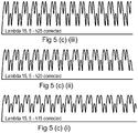
- Figures 5(a) to 5(c) (i) to (iii) each show images of spanwise cross sections of leading edges of an aerofoil in accordance with the present disclosure, as viewed from either the suction or pressure surface.
- the leading edge profile of each of figures 5(a) to 5(c) corresponds to the waveform in figures 4(a) to 4(c) respectively.
- the maximum amplitude of the resultant superimposed waveform (which corresponds to the maximum extent of the projections from the minimum chordal extent relative to the mean chord length, h max / c 0 ) corresponds to 0.1, 0.133 and 0.167 respectively.
- both the waveform and the maximum extent of the projections will have an impact both on the aerodynamics of the aerofoil, and the noise attenuation properties of the aerofoil.
- This repeating pattern of projections and recesses / troughs produces a leading edge profile comprising repeating at least first and second chordwise extending recesses having different extents relative to the mean chord line, separated in a spanwise direction by at least first and second generally chordwise extending projections having different extents relative to the mean chord line.
- the first recesses are separated by second recesses, such that alternating first and second recesses are provided.
- the leading edge profile shown in figure 4(b) also comprises a continuous forward and rearward sweeping curve extending in a direction extending from the root to the tip.
- the pattern comprises a first forward extending protrusion 150 extending a relatively large extent beyond from the mean chord line, followed by a relatively small first recess 152 such that the leading edge extends less than the mean chord line c 0 , followed by a relatively small second forward extending protrusion 154 extending forwardly of the mean chord line to a lesser extent than either the first recess 152 extends less than the mean chord line or the first protrusion extends forward of the mean chord line c 0 , followed by a small second recess 156 extending less than the mean chord line to the same extent that the second forward extending protrusion 150 extends beyond the mean chord line c 0 , followed by a 158 third forward protrusion extending forwardly of the mean chord line to a lesser extent than the first protrusion 150, but a greater extent than the second protrusion
- the leading edge profile of figure 4(b) comprises first, second and third projections, each having a different extent to one another and spaced from one another, and first, second and third recesses, which are similarly spaced in a spanwise direction and have different extents, i.e. their nadirs are spaced in a chordal direction.
- the leading edge profile shown in figure 5(c) defines a pair of forward extending protrusions 250, 254 extending a relatively large extent beyond from the mean chord line separated in a spanwise direction by a recess.
- the forward extending protrusions 250, 254 are followed by a pair of inwardly extending recesses 256, 260 which have an extent such that the leading edge extends less than the mean chord line to the same extent as the forward extending protrusions 250, 254 extend beyond the mean chord line c 0 .
- the leading edge profile then returns to the mean chord line c 0 , where the pattern is repeated.
- leading edge profile of figure 5(c) comprises first and second generally chordwise extending projections, with each first projection being spaced apart by two second projections.
- Figure 9 shows a cross sectional view through the OGV 32 along the line A-A shown in figure 3 , and the line B-B shown in figure 3 , in each case the OGV 32 being sectioned along a line extending in a generally chordwise direction from the leading to the trailing edge.
- y is representative of the thickness of the aerofoil at chordwise position x and spanwise position r
- FIG. 9 This profile is illustrated in figure 9 (which is not drawn to scale), wherein the cross section A-A (shown in dotted lines) represents the region 0 ⁇ x,1, and the cross section B-B (shown in solid lines) represents the region 0 ⁇ x ⁇ 2/3c 0 .
- the first 2/3 of the chordal distance between the trailing edge and the mean chord line is defined by an NACA-65 series aerofoil profile (though it will be understood that other aerofoil profiles could be used).
- section B-B therefore, the cross-sectional shape corresponds entirely to the NACA-65 series aerofoil shape.
- chordal distance of this portion of the cross sectional profile is adjusted by a factor x/c(r). Consequently, the leading edge third of the chordal extent of the NACA-65 profile is transformed (i.e. "stretched") at different spanwise locations by a factor determined by the superimposed waveform, i.e. the chordal extent is linearly transformed by a factor 1/c(r).
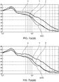
- Figures 6(a) (i) to 6(a) (iii) show the perceived noise (dB) of various leading edge profiles of various plates having otherwise similar dimensions, under similar conditions at an airflow velocity of 20 m/s.
- line X represents a flat plate having a straight leading edge.
- Line Y represents a plate having a leading edge comprising projections defined by a waveform composed of a single sinusoidal wave having a single wavelength relative to the mean chord distance of 0.033 ⁇ / c 0
- line Z represents a plate having a leading edge comprising projections defined by a waveform composed of a single sinusoidal wave having a single wavelength relative to the mean chord distance of 0.067 ⁇ / c 0 .
- Line (a)(i) represents a plate having the leading edge profile shown in figure 5(a)(i) .
- all of the flat plates having serrated leading edge profiles show a reduced noise profile across a wide range of frequencies from around 10 2 to 10 4 Hz, which represents the edge of normal human hearing.
- the double frequency leading edge profile plate shows a pronounced reduction in noise compared to the single frequency plates, particularly at frequencies around 10 3 Hz. Consequently, the disclosed aerofoil profile provides reduced aerodynamic noise in use.
- the recesses / troughs located between each projection at downstream positions in the in use flow direction produce tone noise out of phase with noise produced by recesses / toughs upstream. Consequently, the noise cancels out, reducing overall noise.
- This destructive interference effect is an additional noise reduction mechanism that is not present for single frequency serrations, leading to additional reductions in radiated noise from the aerofoil leading edge, which are additional to the reductions in noise provided by a serrated leading edge.
- first tone noise produced by the first recess is cancelled by the second recess
- different tone noise i.e. at a different frequency
- tone noise at a third frequency produced by the second recess is cancelled by the third recess, in view of the distance between the second and third recess, where tis is different to the distance between either the first and second recess, or the first and third recess. Consequently, such an arrangement may provide a wider broadband noise reduction compared to waveforms having only first and second chordally spaced recesses.
- line X again represents the flat plate having a straight leading edge.
- Line Y and Z represent plates having similar leading edge serrations to those of figure 6(a)(ii) , but with a maximum height relative to the mean chord distance h max / c 0 of 0.133.
- Line (a) represents a plate having the leading edge profile shown in figure 5(a)(ii) (i.e. having longer protrusions relative to those of figure 5(a)(ii) .
- the plate having a leading edge having double wavelength protrusions shows improved nose reduction performance.
- the noise reduction of the double wavelength protrusion leading edge compared to the straight and single wavelength protrusion leading edges is particularly pronounced at lower frequencies, peaking at around 700 Hz.
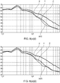
- Figure 7(a)(i) shows test results of the same leading edge profiles X, Y, Z, and (a)(i) of figure 6(i) , but with the airflow velocity increased to 40 m/s.
- the double wavelength leading edge protrusions again outperform the baseline and single wavelength leading edge protrusions in terms of noise attenuation.
- the relative reduction in noise occurs at higher frequencies, in this case, 1000 to 2000 Hz.
- Figures 7(a)(ii) and 7(a)(iii) show results from experiments on the same leading edge profiles as shown in figures 6(a)(ii) and 6(a)(iii) respectively, but again at 40 m/s. Again, in each case, the frequency spectrum of the relative noise reduction is altered. Consequently, it will be understood that the designer will select a protrusion length which best suits the noise profile at the typical in use airflow velocities likely to be encountered.
- Figure 8(a)(i) to 8(a)(iii) shows results from similar experiments as those shown in figure 6(i) to 6(iii) , but with the airflow velocity increased again to 60 m/s. Again, the sound attenuation spectrum is altered, in each case to a peak performance at around 3000 Hz. However, as can be seen in figure 8(iii) , the noise attenuation performance for double wavelength protrusions having a height h max / c 0 of 0.167 is inferior to that of single wavelength protrusions at higher frequencies, above around 3000 Hz. However, since these frequencies are perceived less by humans, this may be regarded as a good compromise.
- Figures 6(c)(ii) and 6b(iii) show experimental results for windtunnel tests at 20 m/s for a second set of flat plates.
- X represents a baseline plate
- 6(c)(ii) and 6b(iii) represent the plates shown in figures 5(c)(ii) and 5(c)(iii) respectively.
- the maximum amplitude of the first, second and (if present) further waveforms c j (r) that makeup the superpositioned waveform are the same. It has been found in experimentation that, by keeping the maximum amplitude of the waveforms c j (r) the same provides an enhanced noise reduction over a narrow frequency bandwidth.
- the disclosed leading edge serration waveform envisages superpositioned waveforms having different maximum amplitudes.
- the invention is not limited to the embodiments above-described and various modifications and improvements can be made without departing from the concepts described herein.
- the invention could be employed in aerofoils of different parts of a gas turbine engine, different parts of an aircraft, or in non-aviation applications, such as wind turbines, marine propellers, industrial cooling fans, and other aerofoils in which noise is a consideration.
- the invention has been found to be effective for a wide range of aerofoil cross sectional profiles, and also for flat plate aerofoils.
Landscapes
- Engineering & Computer Science (AREA)
- Mechanical Engineering (AREA)
- General Engineering & Computer Science (AREA)
- Physics & Mathematics (AREA)
- Fluid Mechanics (AREA)
- Structures Of Non-Positive Displacement Pumps (AREA)
Description
- The present disclosure concerns an aerofoil, particularly but not exclusively, an aerofoil for a gas turbine engine having a reduced broadband noise profile in use.
- Noise from aircraft is an ongoing environmental concern. There are typically several sources of noise from an aircraft, including jet noise produced by shear interaction between the jet exhaust from gas turbine engines, and aerodynamic noise caused primarily by turbulent air created by the flow of air over aircraft surfaces.
- As aircraft engine bypass ratios are increased, aircraft aerodynamic noise is becoming a relatively large contributor to overall aircraft noise. In particular, turbulence created on the leading and trailing edges of aerofoil surfaces is thought to produce a significant proportion of noise produced by an aircraft. Noise created by these mechanisms often has a wide range of frequencies (known as "broadband noise"), and is particularly difficult to eliminate.
- Examples of aerofoils on aircraft include the wings and tail surfaces, as well as smaller components such as control surfaces and high lift devices such as flaps and slats. The gas turbine engines of the aircraft also typically include several aerofoils, including compressor and turbine rotors and stators, fan rotors and Outlet Guide Vanes (OGV). The gas turbine engine nacelle is also typically aerofoil shaped.
- It has been proposed to provide wave-like projections on the leading edge of an aerofoil, as proposed for example in
US6431498 . It is thought that such projections reduce drag as well as reduce noise to some extent, as evidenced for example inUS2013164488 . Such projections have been proposed for both fixed and rotating aerofoils, as proposed for example inUS2011058955 . However, such projections do not eliminate noise completely, and it is therefore desirable to provide an aerofoil having improved noise attenuation properties.GB2497739 -
GB2493293 -
WO11157849
The term "chord" will be understood to refer to the distance between the leading and trailing edge of an aerofoil, measured parallel to the normal airflow over the wing. The term "chordal" will be understood to refer to a direction parallel to the chord. The term "span" will be understood to refer to a direction generally normal to the chord, extending between a root and a tip of an aerofoil component. - According to a first aspect of the disclosure there is provided an aerofoil component defining an in use leading edge and a trailing edge, the leading edge defining a waveform profile, wherein the waveform profile extends in a spanwise direction and comprises a superposition of a first wave and a second wave, the first and second waves having different wavelengths such that the waveform profile defines a plurality of first and second generally chordwise extending recesses spaced in a spanwise direction and having a different extent in the chordwise direction, characterised in that the waveform profile is of the form

- Advantageously, it has been found that the disclosed aerofoil provides reduce broadband noise when in use compared to prior arrangements.
- One or more first recess may be separated from a further first recess in a spanwise direction by one or more second recess.
- The first and second waves may have substantially the same amplitude.
The waveform may comprise a sinusoidal wave. - γ 1 may have a different value to γ 2. h 1 and h 2 may have the same value.
- In a first example, γ1/c 0 has a value of 1/30, and γ 2/c 0 has a value of 2/30. In a second example, γ 1/c 0 has a value of 2/30, and γ 2/c 0 has a value of 1/10. In a third example, γ 1/c 0 has a value of 1/30, and γ 2/c 0 has a value of 1/10. γ 1/γ 2 may be between ½ and 2.
- h/c 0 may have a value between 1/10 and 1/6. In a first example, h/c 0 has a value of 1/10. In a second example, h/c 0 has a value of 4/30. In a third example, h/c 0 has a value of 1/6.
- The aerofoil may have a cross sectional profile which may vary across the span of the aerofoil in accordance with the formula:

- Where y is representative of the thickness of the aerofoil at chordwise position x and spanwise position r, and f(x) defines an aerofoil cross sectional profile such as an NACA-65 series aerofoil, and wherein x=0 is defined as the trailing edge, and x=1 is defined as the leading edge.
- The aerofoil component may comprise an aerofoil of a gas turbine engine, such as an outlet guide vane (OGV).
- According to a second aspect of the present disclosure there is provided a gas turbine engine comprising an aerofoil component in accordance with the first aspect of the present disclosure.
- According to a third aspect of the present disclosure there is provided an aircraft comprising an aerofoil component in accordance with the first aspect of the present disclosure.
- According to a fourth aspect of the present disclosure there is provided a method of designing an aerofoil component, the method comprising the steps of: defining a first wave and a second wave, the first wave having a different wavelength to the second wave;
superposing the first and second waves to define a superposed waveform of the form
defining an aerofoil component having a leading edge profile comprising the superposed waveform such that the leading edge defines a plurality of first and second generally chordwise extending recesses spaced in a spanwise direction and having a different extent in the chordwise direction. - The skilled person will appreciate that except where mutually exclusive, a feature described in relation to any one of the above aspects of the invention may be applied mutatis mutandis to any other aspect of the invention.
- Embodiments of the invention will now be described by way of example only, with reference to the Figures, in which:
-
Figure 1 is a sectional side view of a gas turbine engine; -
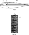
Figure 2 is a perspective view of a prior aerofoil; -
Figure 3 is a plan view from above showing a leading edge of a first aerofoil in accordance with the present disclosure; -
Figures 4a to 4c are schematics showing waveforms of leading edges of aerofoils in accordance with the present disclosure; -
Figures 5a to c (i) to (iii) are plan views from above of leading edges of aerofoils in accordance with the present invention; -
Figures 6a(i) to 6(a)(iiii) are graphs showing experimental results of noise testing of aerofoils shown infigures 5a (i) to (iii) respectively at impinging airspeeds of 20m/s; -
Figures 6(c)(ii) and 6(c)(iii) are graphs showing experimental results of noise testing of aerofoils shown infigures 5c (ii) and (iii) at impinging airspeeds of 20 m/s -
Figures 7(a)(i) to 7(a)(iii) are graphs showing experimental results of noise testing of aerofoils shown infigures 5a (i) to (iii) respectively at impinging airspeeds of 40/s; -
Figures 8(a)(i) to 8(a)(iii) graphs showing experimental results of noise testing of aerofoils shown infigures 5a (i) to (iii) respectively at impinging airspeeds of 60/s; -
Figure 9 is a cross sectional view of an aerofoil in accordance with the present invention; -
Figure 10 is a plan view of a further aerofoil in accordance with the present invention; and -
Figure 11 is a graph showing experimental results of noise testing of the aerofoil shown infigure 10 . -
Figure 1 shows a highbypass turbofan engine 10, having a principal androtational axis 11. Theengine 10 comprises, in axial flow series, anair intake 12, apropulsive fan 13, anintermediate pressure compressor 14, a high-pressure compressor 15,combustion equipment 16, a high-pressure turbine 17, andintermediate pressure turbine 18, a low-pressure turbine 19 and anexhaust nozzle 20. A nacelle 21 generally surrounds theengine 10 and defines both theintake 12 and theexhaust nozzle 20. - The
gas turbine engine 10 works in the conventional manner so that air entering theintake 12 is accelerated by thefan 13 to produce two air flows: a first air flow into theintermediate pressure compressor 14 and a second air flow which passes through abypass duct 22 to provide propulsive thrust. Air directed rearwardly by thefan 12 is directed to an Outlet Guide Vane (OGV) 32, which provides structural support for theengine 10, and removes swirl from the airflow. Theintermediate pressure compressor 14 compresses the air flow directed into it before delivering that air to thehigh pressure compressor 15 where further compression takes place. - The compressed air exhausted from the high-
pressure compressor 15 is directed into thecombustion equipment 16 where it is mixed with fuel and the mixture combusted. The resultant hot combustion products then expand through, and thereby drive the high, intermediate and low-pressure turbines 17, 18, 19 before being exhausted through thenozzle 20 to provide additional propulsive thrust. The high 17, intermediate 18 and low 19 pressure turbines drive respectively thehigh pressure compressor 15,intermediate pressure compressor 14 andfan 13, each by suitable interconnecting shafts. - Each of the
fan 12,compressors turbines fan 12. Consequently, air travelling over the leading and trailing edges of these surfaces can contribute to aircraft noise. Since the core of the engine is shielded by the engine core casing, the majority of the noise emanates from thefan 12,OGV 32 and nacelle. - Part of the
OGV 32 is shown in further detail infigure 3 . In this example, theOGV 32 has an aerofoil profile generally corresponding to an NACA-65 series aerofoil. TheOGV 32 defines aroot 34, atip 36, a leadingedge 38, a trailingedge 40, asuction surface 42 and a pressure surface (not shown) on the opposite side to thesuction surface 42. TheOGV 32 defines a mean chord line C0 defined by a line extending from aroot 34 to atip 36 of theOGV 32 along the arithmetic mean of the position of the leadingedge 38 of theaerofoil 32. - The leading
edge 38 of theaerofoil 32 has a serrated profile defined by a plurality ofprojections 44 separated by first andsecond recesses projection 44 extends in a generally forward, chordwise (i.e. in a direction parallel to airflow in use) direction, and each recesses extends in a generally rearward, chordwise direction such that the leadingedge 38 defines a continuously inwardly and outwardly curving surface. - The plan profile (i.e. the projection of the leading
edge 38 when viewed from either the suction or pressure surface) of theOGV 32 is defined by a waveform, as shown infigure 4(c) . The waveform can be defined by superimposing first and second waves having different wavelengths to form the superposed waveform. - In general, the waveform can be described by the following equation:

- Where c(r) is representative of the spanwise variation of chordwise extent c of the projection from the mean chord line C 0, along the span r, h 1 and h 2 are representative of the amplitude of the 1st and 2nd waveforms respectively, and γ 1 and γ 2 are representative of the wavelength of the 1st and 2nd waveforms respectively,. In other words, the chord length of the aerofoil at a spanwise position r is defined by
formula 1. - In the embodiments shown in
figures 4(a) to 4(c) , two sinusoidal waveforms having wavelengths


figure 4(a) , the ratio is approximately 2. In the embodiment shown infigure 4(b) , theratio 
figure 4(c) , theratio 
- Consequently, the waveform shown in
figure 4(a) can be described by the equation:
- The waveform shown in
figure 4(b) can be described by the equation:
- The waveform shown in
figure 4(c) can be described by the equation:
- Where y represents the position along the chord line, and x represents the chordwise extent of the leading
edge 38 from the mean chord line at position x. -
Figures 5(a) to 5(c) (i) to (iii) each show images of spanwise cross sections of leading edges of an aerofoil in accordance with the present disclosure, as viewed from either the suction or pressure surface. As can be seen, the leading edge profile of each offigures 5(a) to 5(c) corresponds to the waveform infigures 4(a) to 4(c) respectively. In each of figures (i) to (iii), the maximum amplitude of the resultant superimposed waveform (which corresponds to the maximum extent of the projections from the minimum chordal extent relative to the mean chord length, hmax / c0) corresponds to 0.1, 0.133 and 0.167 respectively. As will be understood, both the waveform and the maximum extent of the projections will have an impact both on the aerodynamics of the aerofoil, and the noise attenuation properties of the aerofoil. - As can be seen, the resultant leading edge profile shown in
figure 4(a) comprises a continuous forward and rearward sweeping curve extending in a direction extending from the root to the tip. A pattern is defined, comprising a firstforward extending protrusion 50 extending a relatively large extent beyond from the mean chord line c0, followed by a relatively smallfirst recess 52 such that the leading edge extends less than the mean chord line c0 at thefirst recess 52, followed by a relatively small secondforward extending protrusion 54 extending forwardly of the mean chord line c0 to the same extent that thefirst recess 52 extends less than the mean chord line c0, followed by a largesecond recess 56 extending less than the mean chord line c0 to the same extent that the firstforward extending protrusion 50 extends beyond the mean chord line c0. The leading edge profile then returns to the mean chord line c0, where the pattern is repeated. It will be understood that the pattern could be reversed, extending from the tip to the root. - This repeating pattern of projections and recesses / troughs produces a leading edge profile comprising repeating at least first and second chordwise extending recesses having different extents relative to the mean chord line, separated in a spanwise direction by at least first and second generally chordwise extending projections having different extents relative to the mean chord line. In the example shown in
figure 5(a) , the first recesses are separated by second recesses, such that alternating first and second recesses are provided. - The leading edge profile shown in
figure 4(b) also comprises a continuous forward and rearward sweeping curve extending in a direction extending from the root to the tip. The pattern comprises a firstforward extending protrusion 150 extending a relatively large extent beyond from the mean chord line, followed by a relatively smallfirst recess 152 such that the leading edge extends less than the mean chord line c0, followed by a relatively small secondforward extending protrusion 154 extending forwardly of the mean chord line to a lesser extent than either thefirst recess 152 extends less than the mean chord line or the first protrusion extends forward of the mean chord line c0, followed by a smallsecond recess 156 extending less than the mean chord line to the same extent that the secondforward extending protrusion 150 extends beyond the mean chord line c0, followed by a 158 third forward protrusion extending forwardly of the mean chord line to a lesser extent than thefirst protrusion 150, but a greater extent than thesecond protrusion 156, followed by a third recess 160 extending less than the mean chord line c0 to the same extent that thethird protrusion 158 extends forward of the mean chord line c0. The leading edge profile then returns to the mean chord line c0, where the pattern is repeated. - Consequently, the leading edge profile of
figure 4(b) comprises first, second and third projections, each having a different extent to one another and spaced from one another, and first, second and third recesses, which are similarly spaced in a spanwise direction and have different extents, i.e. their nadirs are spaced in a chordal direction. - The leading edge profile shown in
figure 5(c) defines a pair of forward extendingprotrusions forward extending protrusions recesses forward extending protrusions - Consequently, the leading edge profile of
figure 5(c) comprises first and second generally chordwise extending projections, with each first projection being spaced apart by two second projections. -
Figure 9 shows a cross sectional view through theOGV 32 along the line A-A shown infigure 3 , and the line B-B shown infigure 3 , in each case theOGV 32 being sectioned along a line extending in a generally chordwise direction from the leading to the trailing edge. - The chordal cross sectional profile of the
OGV 32 can be described in accordance with the following equation:
- Where y is representative of the thickness of the aerofoil at chordwise position x and spanwise position r, and f(x) defines an aerofoil profile such as an NACA-65 series aerofoil, and wherein x=0 is defined as the trailing edge, and x=1 is defined as the leading edge.
- This profile is illustrated in
figure 9 (which is not drawn to scale), wherein the cross section A-A (shown in dotted lines) represents theregion 0<x,1, and the cross section B-B (shown in solid lines) represents theregion 0<x<2/3c0. The first 2/3 of the chordal distance between the trailing edge and the mean chord line is defined by an NACA-65 series aerofoil profile (though it will be understood that other aerofoil profiles could be used). In the case of section B-B therefore, the cross-sectional shape corresponds entirely to the NACA-65 series aerofoil shape. For the remainder of the aerofoil cross sectional however, from the 2/3 points to the leading edge, the chordal distance of this portion of the cross sectional profile is adjusted by a factor x/c(r). Consequently, the leading edge third of the chordal extent of the NACA-65 profile is transformed (i.e. "stretched") at different spanwise locations by a factor determined by the superimposed waveform, i.e. the chordal extent is linearly transformed by afactor 1/c(r). - In a first experimental series, flat plates representative of the leading edge profiles shown in
figures 5(a) (i) to (iii), 5(c)(ii) and5(c)(iii) were tested in a wind tunnel at sea level pressure over a range of airflow velocities (U = 20, 40, 60 and 80 m/s). In each case, a metallic flat plate of 2 mm thick [150 mm x 450 m] was constructed by joining two flat plates each of 1 mm thick. This type of construction provides a slot at the leading edge of the flat plate for mounting the double frequency serration inserts cut from acrylic sheet of 2 mm thickness. The trailing edge of the flat plate was sharpened to eliminate vortex shedding noise.Figures 6(a) (i) to 6(a) (iii) show the perceived noise (dB) of various leading edge profiles of various plates having otherwise similar dimensions, under similar conditions at an airflow velocity of 20 m/s. Infigure 6(a)(i) , line X represents a flat plate having a straight leading edge. Line Y represents a plate having a leading edge comprising projections defined by a waveform composed of a single sinusoidal wave having a single wavelength relative to the mean chord distance of 0.033 γ / c0, and line Z represents a plate having a leading edge comprising projections defined by a waveform composed of a single sinusoidal wave having a single wavelength relative to the mean chord distance of 0.067 γ / c0. In each case, the maximum height of the protrusions relative to the mean chord distance h / c0 is 0.1. Line (a)(i) represents a plate having the leading edge profile shown infigure 5(a)(i) . As can be seen, all of the flat plates having serrated leading edge profiles show a reduced noise profile across a wide range of frequencies from around 102 to 104 Hz, which represents the edge of normal human hearing. However, the double frequency leading edge profile plate shows a pronounced reduction in noise compared to the single frequency plates, particularly at frequencies around 103 Hz. Consequently, the disclosed aerofoil profile provides reduced aerodynamic noise in use. - Without wishing to be restricted to theory, it is thought that the recesses / troughs located between each projection at downstream positions in the in use flow direction produce tone noise out of phase with noise produced by recesses / toughs upstream. Consequently, the noise cancels out, reducing overall noise. This is thought to be because the leading edge profile comprises similar troughs separated in a flow-wise direction htt . Since these troughs have similar geometry, they radiate similar tone noise, delayed in time by U/htt , where U is the flow velocity in the flow-wise direction. At a radiation frequency of ω=2πf, this time delay translates to a phase shift of ωU/htt. There therefore exists a particular (angular) frequency ω0, at which the radiation from adjacent troughs are 180° out of phase, i.e.,


- This destructive interference effect is an additional noise reduction mechanism that is not present for single frequency serrations, leading to additional reductions in radiated noise from the aerofoil leading edge, which are additional to the reductions in noise provided by a serrated leading edge.
- In the case where there are more than two chordally spaced recesses (such as for the waveform shown in
figure 4(b) ), first tone noise produced by the first recess is cancelled by the second recess, and different tone noise (i.e. at a different frequency) is cancelled by the second recess, in view of the different distances between the first, second and third recesses. Similarly, tone noise at a third frequency produced by the second recess is cancelled by the third recess, in view of the distance between the second and third recess, where tis is different to the distance between either the first and second recess, or the first and third recess. Consequently, such an arrangement may provide a wider broadband noise reduction compared to waveforms having only first and second chordally spaced recesses. - Similarly, in
figure 6(a)(ii) , line X again represents the flat plate having a straight leading edge. Line Y and Z represent plates having similar leading edge serrations to those offigure 6(a)(ii) , but with a maximum height relative to the mean chord distance hmax / c0 of 0.133. Line (a) represents a plate having the leading edge profile shown infigure 5(a)(ii) (i.e. having longer protrusions relative to those offigure 5(a)(ii) . Again, the plate having a leading edge having double wavelength protrusions shows improved nose reduction performance. However, in this case, the noise reduction of the double wavelength protrusion leading edge compared to the straight and single wavelength protrusion leading edges is particularly pronounced at lower frequencies, peaking at around 700 Hz. - In
figure 6(a)(iii) , the leading edge profile offigure 5(a)(iii) is compared to lines Y and Z, which are single wavelength protrusion leading edges wherein h / c0 is 0.167. Again, the frequency profile of noise reduction is shifted to slightly lower frequencies. In general, it can be observed from these results that the frequency at which the maximum noise attenuation relative to the baseline leading edge occurs is approximately inversely proportional to the maximum amplitude of the protrusions relative to the chord distance hmax / c0. This appears to be the case irrespective of relative airflow velocity. Conveniently therefore, a designer can choose a maximum protrusion height resulting in a noise reduction corresponding to the frequency of most interest. -
Figure 7(a)(i) , shows test results of the same leading edge profiles X, Y, Z, and (a)(i) offigure 6(i) , but with the airflow velocity increased to 40 m/s. In this case, it can be seen that the double wavelength leading edge protrusions again outperform the baseline and single wavelength leading edge protrusions in terms of noise attenuation. However, at these velocities, the relative reduction in noise occurs at higher frequencies, in this case, 1000 to 2000 Hz.Figures 7(a)(ii) and 7(a)(iii) show results from experiments on the same leading edge profiles as shown infigures 6(a)(ii) and6(a)(iii) respectively, but again at 40 m/s. Again, in each case, the frequency spectrum of the relative noise reduction is altered. Consequently, it will be understood that the designer will select a protrusion length which best suits the noise profile at the typical in use airflow velocities likely to be encountered. -
Figure 8(a)(i) to 8(a)(iii) shows results from similar experiments as those shown infigure 6(i) to 6(iii) , but with the airflow velocity increased again to 60 m/s. Again, the sound attenuation spectrum is altered, in each case to a peak performance at around 3000 Hz. However, as can be seen infigure 8(iii) , the noise attenuation performance for double wavelength protrusions having a height hmax / c0 of 0.167 is inferior to that of single wavelength protrusions at higher frequencies, above around 3000 Hz. However, since these frequencies are perceived less by humans, this may be regarded as a good compromise. - Further experimental results were obtained for airflow velocities of 80 m/s. Again, it was found that the double wavelength protrusions outperformed the noise attenuation properties of the single wavelength protrusions over a wide frequency range. It is expected that similar results would be obtained at still higher airflow velocities. From these results, it would appear that the frequency at which the maximum noise reduction relative to the baseline straight leading edge occurs is approximately proportional to the relatively airflow velocity at the leading edge. In the context of an OGV, this would be the mean jet flow velocity.
-
Figures 6(c)(ii) and 6b(iii) show experimental results for windtunnel tests at 20 m/s for a second set of flat plates. Again, X represents a baseline plate, Y and Z represent plates having γ / c0 = 0.067 and 0.1 respectively, and 6(c)(ii) and 6b(iii) represent the plates shown infigures 5(c)(ii) and 5(c)(iii) respectively. As can be seen from a comparison with the results shown infigures 6(a)(ii) and6(a)(iii) , the noise attenuation is less pronounced compared to prior arrangements, and so the arrangement shown infigure 4(a) is thought to be more effective than that shown infigure 4(c) . - In each of the above described waveforms, the maximum amplitude of the first, second and (if present) further waveforms cj(r) that makeup the superpositioned waveform are the same. It has been found in experimentation that, by keeping the maximum amplitude of the waveforms cj(r) the same provides an enhanced noise reduction over a narrow frequency bandwidth. However, the disclosed leading edge serration waveform envisages superpositioned waveforms having different maximum amplitudes.
- In a second experimental series, an aerofoil having a leading edge waveform with h/c0 = 0.167, γ1 = 0.067, γ1 = 0.133 and an aerofoil cross sectional profile corresponding to an NACA-65 series aerofoil was tested in a windtunnel under representative conditions with airflows at 20m/s. An image of the leading edge of the test aerofoil α is shown in
figure 10 . The results from these tests are shown infigure 11 . - As can be seen, the noise at frequencies between 400 Hz and 800 Hz is reduced relative to prior arrangements. Similar experiments were conducted for the same aerofoil at higher airflow velocities. In those tests, the frequency at which maximum noise attenuation was achieved increased approximately linearly with airflow velocity. Consequently, the results from the tests with flat plates are verified.
- It has been found from further experiments that an important parameter for achieving maximum noise attenuation at a particular frequency f is the downstream distance between nadirs of first and second troughs, htt (see
figure 10 ). In particular, a maximum noise attenuation frequency f can be calculated for a given distance htt at a given streamwise velocity U using the following equation:
- Thus in the example shown in
figure 10 , for a flow velocity of 20 metres per second, and an htt of 2 cm gives a peak noise attenuation frequency of 500 Hz. This is consistent with the results found by experimentation (see figure z). - It will be understood that the invention is not limited to the embodiments above-described and various modifications and improvements can be made without departing from the concepts described herein. For example, the invention could be employed in aerofoils of different parts of a gas turbine engine, different parts of an aircraft, or in non-aviation applications, such as wind turbines, marine propellers, industrial cooling fans, and other aerofoils in which noise is a consideration. The invention has been found to be effective for a wide range of aerofoil cross sectional profiles, and also for flat plate aerofoils.
- Except where mutually exclusive, any of the features may be employed separately or in combination with any other features and the disclosure extends to and includes all combinations and sub-combinations of one or more features described herein.
Claims (11)
- An aerofoil component (32) defining an in use leading edge (38) and a trailing edge (40the leading edge defining a waveform profile, wherein the waveform profile c(r) extends in a spanwise direction and comprises a superposition of a first wave and a second wave, the first and second waves having different wavelengths (γ) such that the waveform profile defines a plurality of first and second generally chordwise extending recesses (46a, 46b) spaced in the spanwise direction and having a different extent in the chordwise direction, characterised in that the waveform profile is of the form

- A component according to claim 1, wherein one or more first recess (46a) is separated from a further first recess (46a) in a spanwise direction by one or more second recess (46b).
- A component according to claim 1 or claim 2, wherein the first and second waves have substantially the same amplitude.
- A component according to any of the preceding claims, wherein γ 1/γ 2 is between ½ and 2.
- A component according to any of the preceding claims, wherein h/c 0 is between 1/10 and 1/6.
- A component according to any of the preceding claims, wherein the aerofoil cross sectional profile of the aerofoil (32) varies across the span of the aerofoil in accordance with the formula:

- A component according to any of the preceding claims, wherein the aerofoil component (32) comprises an aerofoil of a gas turbine engine (10).
- A component according to claim 7, wherein the aerofoil component comprises an outlet guide vane (32) of a gas turbine engine (10).
- A gas turbine engine (10) comprising an aerofoil component (32) in accordance with any of the preceding claims.
- An aircraft comprising a gas turbine engine (10) in accordance with claim 10.
- A method of designing a leading edge (40) of an aerofoil component (32), the method comprising the steps of:defining a first wave and a second wave, the first wave having a different wavelength to the second wave; characterised in that the method further comprises the steps of:superposing the first and second wave to define a superposed waveform of the form
 defining an aerofoil component (32) having a leading edge (40) profile comprising the superposed waveform c(r) such that the leading edge defines a plurality of first and second generally chordwise extending recesses spaced in a spanwise direction and having a different extent in the chordwise direction.
Applications Claiming Priority (1)
| Application Number | Priority Date | Filing Date | Title |
|---|---|---|---|
| GBGB1512688.1A GB201512688D0 (en) | 2015-07-20 | 2015-07-20 | Aerofoil |
Publications (2)
| Publication Number | Publication Date |
|---|---|
| EP3121376A1 EP3121376A1 (en) | 2017-01-25 |
| EP3121376B1 true EP3121376B1 (en) | 2017-09-13 |
Family
ID=54013280
Family Applications (1)
| Application Number | Title | Priority Date | Filing Date |
|---|---|---|---|
| EP16179463.1A Active EP3121376B1 (en) | 2015-07-20 | 2016-07-14 | Aerofoil |
Country Status (3)
| Country | Link |
|---|---|
| US (1) | US10301942B2 (en) |
| EP (1) | EP3121376B1 (en) |
| GB (1) | GB201512688D0 (en) |
Cited By (1)
| Publication number | Priority date | Publication date | Assignee | Title |
|---|---|---|---|---|
| DE102021105226A1 (en) | 2020-03-10 | 2021-09-16 | Ebm-Papst Mulfingen Gmbh & Co. Kg | Fan and fan blades |
Families Citing this family (11)
| Publication number | Priority date | Publication date | Assignee | Title |
|---|---|---|---|---|
| EP3181895A1 (en) * | 2015-12-17 | 2017-06-21 | LM WP Patent Holding A/S | Splitter plate arrangement for a serrated wind turbine blade |
| GB201707836D0 (en) | 2017-05-16 | 2017-06-28 | Oscar Propulsion Ltd | Outlet guide vanes |
| US10829198B2 (en) * | 2017-06-21 | 2020-11-10 | The Boeing Company | Krueger flap apparatus and methods incorporating a bullnose having a contour variation along a spanwise direction |
| FR3078101B1 (en) * | 2018-02-16 | 2020-11-27 | Safran Aircraft Engines | TURBOMACHINE WITH FLOW SEPARATION NOZZLE WITH SERRATED PROFILE |
| FR3078098B1 (en) | 2018-02-16 | 2020-06-19 | Safran Aircraft Engines | PROFILE STRUCTURE IN INCLINED LOCKINGS |
| GB201809353D0 (en) * | 2018-06-07 | 2018-07-25 | Rolls Royce Plc | Aerofoil |
| GB201818839D0 (en) * | 2018-11-19 | 2019-01-02 | Cambridge Entpr Ltd | Foils with serrations |
| GB201906920D0 (en) | 2019-05-16 | 2019-07-03 | Univ Brunel | Method of reducing noise from an aerofoil |
| US11965425B2 (en) | 2022-05-31 | 2024-04-23 | General Electric Company | Airfoil for a turbofan engine |
| US12012898B2 (en) | 2022-11-03 | 2024-06-18 | General Electric Company | Gas turbine engine with acoustic spacing of the fan blades and outlet guide vanes |
| WO2024108302A1 (en) * | 2022-11-23 | 2024-05-30 | Biomerenewables Inc. | Structure with serrations adapted to traverse a fluid environment |
Family Cites Families (26)
| Publication number | Priority date | Publication date | Assignee | Title |
|---|---|---|---|---|
| GB1560683A (en) * | 1972-11-28 | 1980-02-06 | Rolls Royce | Turbine blade |
| IT1036993B (en) * | 1974-07-02 | 1979-10-30 | Rotron Inc | DEVICE FOR THE MOVEMENT OF A FLUID |
| US4720239A (en) * | 1982-10-22 | 1988-01-19 | Owczarek Jerzy A | Stator blades of turbomachines |
| US4830315A (en) * | 1986-04-30 | 1989-05-16 | United Technologies Corporation | Airfoil-shaped body |
| US5386955A (en) * | 1986-05-22 | 1995-02-07 | Rolls-Royce Plc | Control of fluid flow |
| US5088665A (en) * | 1989-10-31 | 1992-02-18 | The United States Of America As Represented By The Administrator Of The National Aeronautics And Space Administration | Serrated trailing edges for improving lift and drag characteristics of lifting surfaces |
| NL9301910A (en) * | 1993-11-04 | 1995-06-01 | Stork Prod Eng | Wind turbine. |
| US5642985A (en) * | 1995-11-17 | 1997-07-01 | United Technologies Corporation | Swept turbomachinery blade |
| US6431498B1 (en) | 2000-06-30 | 2002-08-13 | Philip Watts | Scalloped wing leading edge |
| US6733240B2 (en) * | 2001-07-18 | 2004-05-11 | General Electric Company | Serrated fan blade |
| DE502004009528D1 (en) * | 2004-06-02 | 2009-07-09 | Rolls Royce Deutschland | Compressor blade with reduced aerodynamic blade excitation |
| JP4973249B2 (en) * | 2006-03-31 | 2012-07-11 | ダイキン工業株式会社 | Multi-wing fan |
| US8083487B2 (en) * | 2007-07-09 | 2011-12-27 | General Electric Company | Rotary airfoils and method for fabricating same |
| US20090074585A1 (en) * | 2007-09-19 | 2009-03-19 | General Electric Company | Wind turbine blades with trailing edge serrations |
| FR2937078B1 (en) * | 2008-10-13 | 2011-09-23 | Snecma | TURBINE DAWN WITH IMPROVED AERODYNAMIC PERFORMANCES. |
| KR101016010B1 (en) | 2009-04-08 | 2011-02-23 | 건국대학교 산학협력단 | Rotor blade for rotary wing aircraft having deformable protrusions to reduce BVI Noiseblade vortex interaction noise |
| WO2011114285A2 (en) * | 2010-03-17 | 2011-09-22 | Sensile Pat Ag | Micropump |
| WO2011157849A2 (en) * | 2010-06-18 | 2011-12-22 | Suzlon Blade Technology B.V. | Rotor blade for a wind turbine |
| GB201016455D0 (en) * | 2010-09-30 | 2010-11-17 | Imp Innovations Ltd | Fluid flow modification |
| US8460779B2 (en) * | 2011-03-30 | 2013-06-11 | General Electric Company | Microstructures for reducing noise of a fluid dynamic structure |
| US8414261B2 (en) * | 2011-05-31 | 2013-04-09 | General Electric Company | Noise reducer for rotor blade in wind turbine |
| US9341158B2 (en) * | 2011-12-08 | 2016-05-17 | Inventus Holdings, Llc | Quiet wind turbine blade |
| GB2497739A (en) * | 2011-12-19 | 2013-06-26 | Rolls Royce Plc | Rotor blade with serrated trailing edge |
| US9121294B2 (en) * | 2011-12-20 | 2015-09-01 | General Electric Company | Fan blade with composite core and wavy wall trailing edge cladding |
| US9249666B2 (en) * | 2011-12-22 | 2016-02-02 | General Electric Company | Airfoils for wake desensitization and method for fabricating same |
| KR101920085B1 (en) * | 2012-09-12 | 2018-11-19 | 엘지전자 주식회사 | Fan |
-
2015
- 2015-07-20 GB GBGB1512688.1A patent/GB201512688D0/en not_active Ceased
-
2016
- 2016-07-14 EP EP16179463.1A patent/EP3121376B1/en active Active
- 2016-07-15 US US15/211,306 patent/US10301942B2/en active Active
Non-Patent Citations (1)
| Title |
|---|
| None * |
Cited By (7)
| Publication number | Priority date | Publication date | Assignee | Title |
|---|---|---|---|---|
| DE102021105226A1 (en) | 2020-03-10 | 2021-09-16 | Ebm-Papst Mulfingen Gmbh & Co. Kg | Fan and fan blades |
| WO2021180559A1 (en) | 2020-03-10 | 2021-09-16 | Ebm-Papst Mulfingen Gmbh & Co. Kg | Fan and fan blades |
| DE102021105225A1 (en) | 2020-03-10 | 2021-09-16 | Ebm-Papst Mulfingen Gmbh & Co. Kg | Fan and fan blades |
| WO2021180560A1 (en) | 2020-03-10 | 2021-09-16 | Ebm-Papst Mulfingen Gmbh & Co. Kg | Fan and fan blades |
| EP4083432A1 (en) | 2020-03-10 | 2022-11-02 | ebm-papst Mulfingen GmbH & Co. KG | Fan and fan blade |
| EP4083433A1 (en) | 2020-03-10 | 2022-11-02 | ebm-papst Mulfingen GmbH & Co. KG | Fan and fan blade |
| US11965521B2 (en) | 2020-03-10 | 2024-04-23 | Ebm-Papst Mulfingen Gmbh & Co. Kg | Fan and fan blades |
Also Published As
| Publication number | Publication date |
|---|---|
| US10301942B2 (en) | 2019-05-28 |
| GB201512688D0 (en) | 2015-08-26 |
| EP3121376A1 (en) | 2017-01-25 |
| US20170022820A1 (en) | 2017-01-26 |
Similar Documents
| Publication | Publication Date | Title |
|---|---|---|
| EP3121376B1 (en) | Aerofoil | |
| EP3208420B1 (en) | Aerofoil | |
| JP4130337B2 (en) | Fan blade with serrated part | |
| EP2014870B1 (en) | Airfoil for use in rotary machines | |
| US20200010174A1 (en) | Airfoil for a rotary machine including a propellor assembly | |
| US11859534B2 (en) | Profiled structure and associated turbomachine | |
| EP2350439B1 (en) | Method for optimising the shape of an aerofoil and corresponding aerofoil | |
| US20210039767A1 (en) | Aerofoil | |
| CN113573978B (en) | Airfoil, noise reduction device, turbine, aircraft, watercraft and cooling fan | |
| EP3379030B1 (en) | Fan rotor with flow induced resonance control | |
| EP3379029B1 (en) | Fan rotor with flow induced resonance control | |
| EP3002210B1 (en) | Engine nacelle | |
| US11105344B2 (en) | Aerofoil | |
| EP3480427B1 (en) | Aerofoil | |
| US11808246B2 (en) | Method for forming an add-on component for an aerofoil | |
| US11525365B2 (en) | Turbomachine with serrated-profile flow-splitter nose | |
| EP0233501B1 (en) | Configuration of propellers, shrouded propellers and/or fans to decrease the noise of and the cyclic loads on the blades | |
| EP2818637B1 (en) | Gas turbine component for releasing a coolant flow into an environment subject to periodic fluctuations in pressure | |
| EP2733071A2 (en) | Rotor blade | |
| Metzger et al. | Benefits of blade sweep for advanced turboprops | |
| CN110536833B (en) | Downstream surface features attenuating propeller wake acoustic interactions | |
| Woodhead et al. | On the double-rooted trailing edge serration | |
| CN114856712B (en) | Blade with bionic blade top and open rotor with blade | |
| US20240059396A1 (en) | Improved acoustic attenuation device for an aircraft propulsion unit | |
| CN118076802A (en) | Outlet nozzle with serrations for an aircraft propeller |
Legal Events
| Date | Code | Title | Description |
|---|---|---|---|
| PUAI | Public reference made under article 153(3) epc to a published international application that has entered the european phase |
Free format text: ORIGINAL CODE: 0009012 |
|
| STAA | Information on the status of an ep patent application or granted ep patent |
Free format text: STATUS: THE APPLICATION HAS BEEN PUBLISHED |
|
| AK | Designated contracting states |
Kind code of ref document: A1 Designated state(s): AL AT BE BG CH CY CZ DE DK EE ES FI FR GB GR HR HU IE IS IT LI LT LU LV MC MK MT NL NO PL PT RO RS SE SI SK SM TR |
|
| AX | Request for extension of the european patent |
Extension state: BA ME |
|
| STAA | Information on the status of an ep patent application or granted ep patent |
Free format text: STATUS: REQUEST FOR EXAMINATION WAS MADE |
|
| 17P | Request for examination filed |
Effective date: 20170215 |
|
| RBV | Designated contracting states (corrected) |
Designated state(s): AL AT BE BG CH CY CZ DE DK EE ES FI FR GB GR HR HU IE IS IT LI LT LU LV MC MK MT NL NO PL PT RO RS SE SI SK SM TR |
|
| GRAP | Despatch of communication of intention to grant a patent |
Free format text: ORIGINAL CODE: EPIDOSNIGR1 |
|
| STAA | Information on the status of an ep patent application or granted ep patent |
Free format text: STATUS: GRANT OF PATENT IS INTENDED |
|
| INTG | Intention to grant announced |
Effective date: 20170616 |
|
| GRAS | Grant fee paid |
Free format text: ORIGINAL CODE: EPIDOSNIGR3 |
|
| GRAA | (expected) grant |
Free format text: ORIGINAL CODE: 0009210 |
|
| STAA | Information on the status of an ep patent application or granted ep patent |
Free format text: STATUS: THE PATENT HAS BEEN GRANTED |
|
| AK | Designated contracting states |
Kind code of ref document: B1 Designated state(s): AL AT BE BG CH CY CZ DE DK EE ES FI FR GB GR HR HU IE IS IT LI LT LU LV MC MK MT NL NO PL PT RO RS SE SI SK SM TR |
|
| REG | Reference to a national code |
Ref country code: GB Ref legal event code: FG4D |
|
| REG | Reference to a national code |
Ref country code: CH Ref legal event code: EP |
|
| REG | Reference to a national code |
Ref country code: IE Ref legal event code: FG4D |
|
| REG | Reference to a national code |
Ref country code: AT Ref legal event code: REF Ref document number: 928367 Country of ref document: AT Kind code of ref document: T Effective date: 20171015 |
|
| REG | Reference to a national code |
Ref country code: DE Ref legal event code: R096 Ref document number: 602016000391 Country of ref document: DE |
|
| REG | Reference to a national code |
Ref country code: NL Ref legal event code: MP Effective date: 20170913 |
|
| REG | Reference to a national code |
Ref country code: LT Ref legal event code: MG4D |
|
| PG25 | Lapsed in a contracting state [announced via postgrant information from national office to epo] |
Ref country code: NO Free format text: LAPSE BECAUSE OF FAILURE TO SUBMIT A TRANSLATION OF THE DESCRIPTION OR TO PAY THE FEE WITHIN THE PRESCRIBED TIME-LIMIT Effective date: 20171213 Ref country code: SE Free format text: LAPSE BECAUSE OF FAILURE TO SUBMIT A TRANSLATION OF THE DESCRIPTION OR TO PAY THE FEE WITHIN THE PRESCRIBED TIME-LIMIT Effective date: 20170913 Ref country code: FI Free format text: LAPSE BECAUSE OF FAILURE TO SUBMIT A TRANSLATION OF THE DESCRIPTION OR TO PAY THE FEE WITHIN THE PRESCRIBED TIME-LIMIT Effective date: 20170913 Ref country code: HR Free format text: LAPSE BECAUSE OF FAILURE TO SUBMIT A TRANSLATION OF THE DESCRIPTION OR TO PAY THE FEE WITHIN THE PRESCRIBED TIME-LIMIT Effective date: 20170913 Ref country code: LT Free format text: LAPSE BECAUSE OF FAILURE TO SUBMIT A TRANSLATION OF THE DESCRIPTION OR TO PAY THE FEE WITHIN THE PRESCRIBED TIME-LIMIT Effective date: 20170913 |
|
| REG | Reference to a national code |
Ref country code: AT Ref legal event code: MK05 Ref document number: 928367 Country of ref document: AT Kind code of ref document: T Effective date: 20170913 |
|
| PG25 | Lapsed in a contracting state [announced via postgrant information from national office to epo] |
Ref country code: LV Free format text: LAPSE BECAUSE OF FAILURE TO SUBMIT A TRANSLATION OF THE DESCRIPTION OR TO PAY THE FEE WITHIN THE PRESCRIBED TIME-LIMIT Effective date: 20170913 Ref country code: ES Free format text: LAPSE BECAUSE OF FAILURE TO SUBMIT A TRANSLATION OF THE DESCRIPTION OR TO PAY THE FEE WITHIN THE PRESCRIBED TIME-LIMIT Effective date: 20170913 Ref country code: BG Free format text: LAPSE BECAUSE OF FAILURE TO SUBMIT A TRANSLATION OF THE DESCRIPTION OR TO PAY THE FEE WITHIN THE PRESCRIBED TIME-LIMIT Effective date: 20171213 Ref country code: RS Free format text: LAPSE BECAUSE OF FAILURE TO SUBMIT A TRANSLATION OF THE DESCRIPTION OR TO PAY THE FEE WITHIN THE PRESCRIBED TIME-LIMIT Effective date: 20170913 Ref country code: GR Free format text: LAPSE BECAUSE OF FAILURE TO SUBMIT A TRANSLATION OF THE DESCRIPTION OR TO PAY THE FEE WITHIN THE PRESCRIBED TIME-LIMIT Effective date: 20171214 |
|
| PG25 | Lapsed in a contracting state [announced via postgrant information from national office to epo] |
Ref country code: NL Free format text: LAPSE BECAUSE OF FAILURE TO SUBMIT A TRANSLATION OF THE DESCRIPTION OR TO PAY THE FEE WITHIN THE PRESCRIBED TIME-LIMIT Effective date: 20170913 |
|
| PG25 | Lapsed in a contracting state [announced via postgrant information from national office to epo] |
Ref country code: PL Free format text: LAPSE BECAUSE OF FAILURE TO SUBMIT A TRANSLATION OF THE DESCRIPTION OR TO PAY THE FEE WITHIN THE PRESCRIBED TIME-LIMIT Effective date: 20170913 Ref country code: CZ Free format text: LAPSE BECAUSE OF FAILURE TO SUBMIT A TRANSLATION OF THE DESCRIPTION OR TO PAY THE FEE WITHIN THE PRESCRIBED TIME-LIMIT Effective date: 20170913 |
|
| PG25 | Lapsed in a contracting state [announced via postgrant information from national office to epo] |
Ref country code: SM Free format text: LAPSE BECAUSE OF FAILURE TO SUBMIT A TRANSLATION OF THE DESCRIPTION OR TO PAY THE FEE WITHIN THE PRESCRIBED TIME-LIMIT Effective date: 20170913 Ref country code: EE Free format text: LAPSE BECAUSE OF FAILURE TO SUBMIT A TRANSLATION OF THE DESCRIPTION OR TO PAY THE FEE WITHIN THE PRESCRIBED TIME-LIMIT Effective date: 20170913 Ref country code: IS Free format text: LAPSE BECAUSE OF FAILURE TO SUBMIT A TRANSLATION OF THE DESCRIPTION OR TO PAY THE FEE WITHIN THE PRESCRIBED TIME-LIMIT Effective date: 20180113 Ref country code: SK Free format text: LAPSE BECAUSE OF FAILURE TO SUBMIT A TRANSLATION OF THE DESCRIPTION OR TO PAY THE FEE WITHIN THE PRESCRIBED TIME-LIMIT Effective date: 20170913 Ref country code: IT Free format text: LAPSE BECAUSE OF FAILURE TO SUBMIT A TRANSLATION OF THE DESCRIPTION OR TO PAY THE FEE WITHIN THE PRESCRIBED TIME-LIMIT Effective date: 20170913 Ref country code: AT Free format text: LAPSE BECAUSE OF FAILURE TO SUBMIT A TRANSLATION OF THE DESCRIPTION OR TO PAY THE FEE WITHIN THE PRESCRIBED TIME-LIMIT Effective date: 20170913 |
|
| REG | Reference to a national code |
Ref country code: DE Ref legal event code: R097 Ref document number: 602016000391 Country of ref document: DE |
|
| PLBE | No opposition filed within time limit |
Free format text: ORIGINAL CODE: 0009261 |
|
| STAA | Information on the status of an ep patent application or granted ep patent |
Free format text: STATUS: NO OPPOSITION FILED WITHIN TIME LIMIT |
|
| REG | Reference to a national code |
Ref country code: FR Ref legal event code: PLFP Year of fee payment: 3 |
|
| PG25 | Lapsed in a contracting state [announced via postgrant information from national office to epo] |
Ref country code: DK Free format text: LAPSE BECAUSE OF FAILURE TO SUBMIT A TRANSLATION OF THE DESCRIPTION OR TO PAY THE FEE WITHIN THE PRESCRIBED TIME-LIMIT Effective date: 20170913 |
|
| 26N | No opposition filed |
Effective date: 20180614 |
|
| PG25 | Lapsed in a contracting state [announced via postgrant information from national office to epo] |
Ref country code: LU Free format text: LAPSE BECAUSE OF NON-PAYMENT OF DUE FEES Effective date: 20180714 Ref country code: MC Free format text: LAPSE BECAUSE OF FAILURE TO SUBMIT A TRANSLATION OF THE DESCRIPTION OR TO PAY THE FEE WITHIN THE PRESCRIBED TIME-LIMIT Effective date: 20170913 |
|
| REG | Reference to a national code |
Ref country code: BE Ref legal event code: MM Effective date: 20180731 |
|
| REG | Reference to a national code |
Ref country code: IE Ref legal event code: MM4A |
|
| PG25 | Lapsed in a contracting state [announced via postgrant information from national office to epo] |
Ref country code: IE Free format text: LAPSE BECAUSE OF NON-PAYMENT OF DUE FEES Effective date: 20180714 |
|
| PG25 | Lapsed in a contracting state [announced via postgrant information from national office to epo] |
Ref country code: BE Free format text: LAPSE BECAUSE OF NON-PAYMENT OF DUE FEES Effective date: 20180731 |
|
| PG25 | Lapsed in a contracting state [announced via postgrant information from national office to epo] |
Ref country code: MT Free format text: LAPSE BECAUSE OF NON-PAYMENT OF DUE FEES Effective date: 20180714 |
|
| REG | Reference to a national code |
Ref country code: CH Ref legal event code: PL |
|
| PG25 | Lapsed in a contracting state [announced via postgrant information from national office to epo] |
Ref country code: TR Free format text: LAPSE BECAUSE OF FAILURE TO SUBMIT A TRANSLATION OF THE DESCRIPTION OR TO PAY THE FEE WITHIN THE PRESCRIBED TIME-LIMIT Effective date: 20170913 |
|
| PG25 | Lapsed in a contracting state [announced via postgrant information from national office to epo] |
Ref country code: CH Free format text: LAPSE BECAUSE OF NON-PAYMENT OF DUE FEES Effective date: 20190731 Ref country code: LI Free format text: LAPSE BECAUSE OF NON-PAYMENT OF DUE FEES Effective date: 20190731 Ref country code: PT Free format text: LAPSE BECAUSE OF FAILURE TO SUBMIT A TRANSLATION OF THE DESCRIPTION OR TO PAY THE FEE WITHIN THE PRESCRIBED TIME-LIMIT Effective date: 20170913 |
|
| PG25 | Lapsed in a contracting state [announced via postgrant information from national office to epo] |
Ref country code: MK Free format text: LAPSE BECAUSE OF NON-PAYMENT OF DUE FEES Effective date: 20170913 Ref country code: RO Free format text: LAPSE BECAUSE OF FAILURE TO SUBMIT A TRANSLATION OF THE DESCRIPTION OR TO PAY THE FEE WITHIN THE PRESCRIBED TIME-LIMIT Effective date: 20170913 Ref country code: CY Free format text: LAPSE BECAUSE OF FAILURE TO SUBMIT A TRANSLATION OF THE DESCRIPTION OR TO PAY THE FEE WITHIN THE PRESCRIBED TIME-LIMIT Effective date: 20170913 Ref country code: HU Free format text: LAPSE BECAUSE OF FAILURE TO SUBMIT A TRANSLATION OF THE DESCRIPTION OR TO PAY THE FEE WITHIN THE PRESCRIBED TIME-LIMIT; INVALID AB INITIO Effective date: 20160714 |
|
| PG25 | Lapsed in a contracting state [announced via postgrant information from national office to epo] |
Ref country code: AL Free format text: LAPSE BECAUSE OF FAILURE TO SUBMIT A TRANSLATION OF THE DESCRIPTION OR TO PAY THE FEE WITHIN THE PRESCRIBED TIME-LIMIT Effective date: 20170913 |
|
| PG25 | Lapsed in a contracting state [announced via postgrant information from national office to epo] |
Ref country code: SI Free format text: LAPSE BECAUSE OF NON-PAYMENT OF DUE FEES Effective date: 20180714 |
|
| P01 | Opt-out of the competence of the unified patent court (upc) registered |
Effective date: 20230528 |
|
| PGFP | Annual fee paid to national office [announced via postgrant information from national office to epo] |
Ref country code: GB Payment date: 20230725 Year of fee payment: 8 |
|
| PGFP | Annual fee paid to national office [announced via postgrant information from national office to epo] |
Ref country code: FR Payment date: 20230725 Year of fee payment: 8 Ref country code: DE Payment date: 20230726 Year of fee payment: 8 |