EP3121376B1 - Tragflügel - Google Patents
Tragflügel Download PDFInfo
- Publication number
- EP3121376B1 EP3121376B1 EP16179463.1A EP16179463A EP3121376B1 EP 3121376 B1 EP3121376 B1 EP 3121376B1 EP 16179463 A EP16179463 A EP 16179463A EP 3121376 B1 EP3121376 B1 EP 3121376B1
- Authority
- EP
- European Patent Office
- Prior art keywords
- aerofoil
- leading edge
- wave
- profile
- representative
- Prior art date
- Legal status (The legal status is an assumption and is not a legal conclusion. Google has not performed a legal analysis and makes no representation as to the accuracy of the status listed.)
- Active
Links
- 238000000034 method Methods 0.000 claims description 5
- 230000009467 reduction Effects 0.000 description 14
- 238000012360 testing method Methods 0.000 description 11
- 230000000737 periodic effect Effects 0.000 description 7
- 238000002474 experimental method Methods 0.000 description 5
- 238000002485 combustion reaction Methods 0.000 description 3
- 239000012530 fluid Substances 0.000 description 3
- 230000001141 propulsive effect Effects 0.000 description 3
- 230000006870 function Effects 0.000 description 2
- 230000007246 mechanism Effects 0.000 description 2
- 230000004048 modification Effects 0.000 description 2
- 238000012986 modification Methods 0.000 description 2
- 230000005855 radiation Effects 0.000 description 2
- 238000001228 spectrum Methods 0.000 description 2
- 238000010408 sweeping Methods 0.000 description 2
- NIXOWILDQLNWCW-UHFFFAOYSA-N acrylic acid group Chemical group C(C=C)(=O)O NIXOWILDQLNWCW-UHFFFAOYSA-N 0.000 description 1
- 230000006835 compression Effects 0.000 description 1
- 238000007906 compression Methods 0.000 description 1
- 238000010276 construction Methods 0.000 description 1
- 238000001816 cooling Methods 0.000 description 1
- 230000003111 delayed effect Effects 0.000 description 1
- 230000001066 destructive effect Effects 0.000 description 1
- 230000000694 effects Effects 0.000 description 1
- 230000007613 environmental effect Effects 0.000 description 1
- 239000000446 fuel Substances 0.000 description 1
- 230000003993 interaction Effects 0.000 description 1
- 230000001788 irregular Effects 0.000 description 1
- 238000004519 manufacturing process Methods 0.000 description 1
- 239000000203 mixture Substances 0.000 description 1
- 230000010363 phase shift Effects 0.000 description 1
- 239000011148 porous material Substances 0.000 description 1
- 238000011144 upstream manufacturing Methods 0.000 description 1
Images


Classifications
-
- F—MECHANICAL ENGINEERING; LIGHTING; HEATING; WEAPONS; BLASTING
- F01—MACHINES OR ENGINES IN GENERAL; ENGINE PLANTS IN GENERAL; STEAM ENGINES
- F01D—NON-POSITIVE DISPLACEMENT MACHINES OR ENGINES, e.g. STEAM TURBINES
- F01D5/00—Blades; Blade-carrying members; Heating, heat-insulating, cooling or antivibration means on the blades or the members
- F01D5/12—Blades
- F01D5/14—Form or construction
- F01D5/141—Shape, i.e. outer, aerodynamic form
-
- F—MECHANICAL ENGINEERING; LIGHTING; HEATING; WEAPONS; BLASTING
- F01—MACHINES OR ENGINES IN GENERAL; ENGINE PLANTS IN GENERAL; STEAM ENGINES
- F01D—NON-POSITIVE DISPLACEMENT MACHINES OR ENGINES, e.g. STEAM TURBINES
- F01D9/00—Stators
- F01D9/02—Nozzles; Nozzle boxes; Stator blades; Guide conduits, e.g. individual nozzles
- F01D9/04—Nozzles; Nozzle boxes; Stator blades; Guide conduits, e.g. individual nozzles forming ring or sector
- F01D9/041—Nozzles; Nozzle boxes; Stator blades; Guide conduits, e.g. individual nozzles forming ring or sector using blades
-
- F—MECHANICAL ENGINEERING; LIGHTING; HEATING; WEAPONS; BLASTING
- F05—INDEXING SCHEMES RELATING TO ENGINES OR PUMPS IN VARIOUS SUBCLASSES OF CLASSES F01-F04
- F05D—INDEXING SCHEME FOR ASPECTS RELATING TO NON-POSITIVE-DISPLACEMENT MACHINES OR ENGINES, GAS-TURBINES OR JET-PROPULSION PLANTS
- F05D2200/00—Mathematical features
- F05D2200/20—Special functions
- F05D2200/26—Special functions trigonometric
- F05D2200/262—Cosine
-
- F—MECHANICAL ENGINEERING; LIGHTING; HEATING; WEAPONS; BLASTING
- F05—INDEXING SCHEMES RELATING TO ENGINES OR PUMPS IN VARIOUS SUBCLASSES OF CLASSES F01-F04
- F05D—INDEXING SCHEME FOR ASPECTS RELATING TO NON-POSITIVE-DISPLACEMENT MACHINES OR ENGINES, GAS-TURBINES OR JET-PROPULSION PLANTS
- F05D2220/00—Application
- F05D2220/30—Application in turbines
- F05D2220/32—Application in turbines in gas turbines
- F05D2220/323—Application in turbines in gas turbines for aircraft propulsion, e.g. jet engines
-
- F—MECHANICAL ENGINEERING; LIGHTING; HEATING; WEAPONS; BLASTING
- F05—INDEXING SCHEMES RELATING TO ENGINES OR PUMPS IN VARIOUS SUBCLASSES OF CLASSES F01-F04
- F05D—INDEXING SCHEME FOR ASPECTS RELATING TO NON-POSITIVE-DISPLACEMENT MACHINES OR ENGINES, GAS-TURBINES OR JET-PROPULSION PLANTS
- F05D2240/00—Components
- F05D2240/10—Stators
- F05D2240/12—Fluid guiding means, e.g. vanes
- F05D2240/121—Fluid guiding means, e.g. vanes related to the leading edge of a stator vane
-
- F—MECHANICAL ENGINEERING; LIGHTING; HEATING; WEAPONS; BLASTING
- F05—INDEXING SCHEMES RELATING TO ENGINES OR PUMPS IN VARIOUS SUBCLASSES OF CLASSES F01-F04
- F05D—INDEXING SCHEME FOR ASPECTS RELATING TO NON-POSITIVE-DISPLACEMENT MACHINES OR ENGINES, GAS-TURBINES OR JET-PROPULSION PLANTS
- F05D2240/00—Components
- F05D2240/20—Rotors
- F05D2240/30—Characteristics of rotor blades, i.e. of any element transforming dynamic fluid energy to or from rotational energy and being attached to a rotor
- F05D2240/303—Characteristics of rotor blades, i.e. of any element transforming dynamic fluid energy to or from rotational energy and being attached to a rotor related to the leading edge of a rotor blade
-
- F—MECHANICAL ENGINEERING; LIGHTING; HEATING; WEAPONS; BLASTING
- F05—INDEXING SCHEMES RELATING TO ENGINES OR PUMPS IN VARIOUS SUBCLASSES OF CLASSES F01-F04
- F05D—INDEXING SCHEME FOR ASPECTS RELATING TO NON-POSITIVE-DISPLACEMENT MACHINES OR ENGINES, GAS-TURBINES OR JET-PROPULSION PLANTS
- F05D2240/00—Components
- F05D2240/20—Rotors
- F05D2240/30—Characteristics of rotor blades, i.e. of any element transforming dynamic fluid energy to or from rotational energy and being attached to a rotor
- F05D2240/304—Characteristics of rotor blades, i.e. of any element transforming dynamic fluid energy to or from rotational energy and being attached to a rotor related to the trailing edge of a rotor blade
-
- F—MECHANICAL ENGINEERING; LIGHTING; HEATING; WEAPONS; BLASTING
- F05—INDEXING SCHEMES RELATING TO ENGINES OR PUMPS IN VARIOUS SUBCLASSES OF CLASSES F01-F04
- F05D—INDEXING SCHEME FOR ASPECTS RELATING TO NON-POSITIVE-DISPLACEMENT MACHINES OR ENGINES, GAS-TURBINES OR JET-PROPULSION PLANTS
- F05D2250/00—Geometry
- F05D2250/10—Two-dimensional
- F05D2250/18—Two-dimensional patterned
-
- F—MECHANICAL ENGINEERING; LIGHTING; HEATING; WEAPONS; BLASTING
- F05—INDEXING SCHEMES RELATING TO ENGINES OR PUMPS IN VARIOUS SUBCLASSES OF CLASSES F01-F04
- F05D—INDEXING SCHEME FOR ASPECTS RELATING TO NON-POSITIVE-DISPLACEMENT MACHINES OR ENGINES, GAS-TURBINES OR JET-PROPULSION PLANTS
- F05D2260/00—Function
- F05D2260/96—Preventing, counteracting or reducing vibration or noise
-
- Y—GENERAL TAGGING OF NEW TECHNOLOGICAL DEVELOPMENTS; GENERAL TAGGING OF CROSS-SECTIONAL TECHNOLOGIES SPANNING OVER SEVERAL SECTIONS OF THE IPC; TECHNICAL SUBJECTS COVERED BY FORMER USPC CROSS-REFERENCE ART COLLECTIONS [XRACs] AND DIGESTS
- Y02—TECHNOLOGIES OR APPLICATIONS FOR MITIGATION OR ADAPTATION AGAINST CLIMATE CHANGE
- Y02T—CLIMATE CHANGE MITIGATION TECHNOLOGIES RELATED TO TRANSPORTATION
- Y02T50/00—Aeronautics or air transport
- Y02T50/60—Efficient propulsion technologies, e.g. for aircraft
Definitions
- Noise from aircraft is an ongoing environmental concern. There are typically several sources of noise from an aircraft, including jet noise produced by shear interaction between the jet exhaust from gas turbine engines, and aerodynamic noise caused primarily by turbulent air created by the flow of air over aircraft surfaces.
- aerofoils on aircraft include the wings and tail surfaces, as well as smaller components such as control surfaces and high lift devices such as flaps and slats.
- the gas turbine engines of the aircraft also typically include several aerofoils, including compressor and turbine rotors and stators, fan rotors and Outlet Guide Vanes (OGV).
- the gas turbine engine nacelle is also typically aerofoil shaped.
- the first and second periodic variations may provide corresponding periodic variations in the local effective chord length of the blade.
- the first periodic variation may be of saw-tooth or sinusoidal shape.
- the second periodic variation may be provided by slits, holes or a porous material, or may comprise a sinusoidal shape.
- the rotor blade may instead be for a wind turbine.
- the serrations are intended to reduce rotor blade noise.
- GB2493293 discloses a fluid flow modification apparatus having a surface having an edge of length Y over or past which a fluid can flow in use.
- the edge has a virtual boundary of length X where Y is greater than X.
- At least a first portion of the apparatus within the virtual boundary comprises an opening and at least a second portion of the apparatus comprises a projection which extends beyond the virtual boundary to provide the edge.
- the edge is multi-scale and may be formed by at least one of the first portion and the second portion having a perimeter of irregular shape that may also be multi-scale.
- the area enclosed by the virtual boundary may be substantially the same as the area of the surface enclosed by the perimeter of the surface.
- the edge may be a trailing edge of the surface and more than one edge of the surface may be multi-scale.
- the surface may be a vehicle spoiler, aircraft wing, wind turbine or fluid mixing apparatus. A method of manufacturing the apparatus is also disclosed.
- WO11157849 discloses a rotor blade for a wind turbine comprising a leading edge and a trailing edge. At least a part of the trailing edge - in the lengthwise direction of the rotor blade - comprises at least one pre manufactured trailing edge part, where said pre manufactured trailing edge part is arranged to cover at least one lengthwise joint of at least one airfoil surface to one other structural part on the rotor blade, where the pre manufactured trailing edge part has a width of 0 to a certain percentage according to a specific rotor radius of the length of the chord of the rotor blade.
- chord will be understood to refer to the distance between the leading and trailing edge of an aerofoil, measured parallel to the normal airflow over the wing.
- chordal will be understood to refer to a direction parallel to the chord.
- span will be understood to refer to a direction generally normal to the chord, extending between a root and a tip of an aerofoil component.
- the disclosed aerofoil provides reduce broadband noise when in use compared to prior arrangements.
- One or more first recess may be separated from a further first recess in a spanwise direction by one or more second recess.
- the first and second waves may have substantially the same amplitude.
- the waveform may comprise a sinusoidal wave.
- ⁇ 1 may have a different value to ⁇ 2 .
- h 1 and h 2 may have the same value.
- ⁇ 1/ c 0 has a value of 1/30
- ⁇ 2 / c 0 has a value of 2/30
- ⁇ 1 / c 0 has a value of 2/30
- ⁇ 2 / c 0 has a value of 1/10
- ⁇ 1 / c 0 has a value of 1/30
- ⁇ 2 / c 0 has a value of 1/10.
- ⁇ 1 / ⁇ 2 may be between 1 ⁇ 2 and 2.
- h / c 0 may have a value between 1/10 and 1/6.
- h / c 0 has a value of 1/10.
- h / c 0 has a value of 4/30.
- h / c 0 has a value of 1/6.
- y is representative of the thickness of the aerofoil at chordwise position x and spanwise position r
- the aerofoil component may comprise an aerofoil of a gas turbine engine, such as an outlet guide vane (OGV).
- OGV outlet guide vane
- a gas turbine engine comprising an aerofoil component in accordance with the first aspect of the present disclosure.
- an aircraft comprising an aerofoil component in accordance with the first aspect of the present disclosure.
- Figure 1 shows a high bypass turbofan engine 10, having a principal and rotational axis 11.
- the engine 10 comprises, in axial flow series, an air intake 12, a propulsive fan 13, an intermediate pressure compressor 14, a high-pressure compressor 15, combustion equipment 16, a high-pressure turbine 17, and intermediate pressure turbine 18, a low-pressure turbine 19 and an exhaust nozzle 20.
- a nacelle 21 generally surrounds the engine 10 and defines both the intake 12 and the exhaust nozzle 20.
- the gas turbine engine 10 works in the conventional manner so that air entering the intake 12 is accelerated by the fan 13 to produce two air flows: a first air flow into the intermediate pressure compressor 14 and a second air flow which passes through a bypass duct 22 to provide propulsive thrust. Air directed rearwardly by the fan 12 is directed to an Outlet Guide Vane (OGV) 32, which provides structural support for the engine 10, and removes swirl from the airflow.
- OGV Outlet Guide Vane
- the intermediate pressure compressor 14 compresses the air flow directed into it before delivering that air to the high pressure compressor 15 where further compression takes place.
- the compressed air exhausted from the high-pressure compressor 15 is directed into the combustion equipment 16 where it is mixed with fuel and the mixture combusted.
- the resultant hot combustion products then expand through, and thereby drive the high, intermediate and low-pressure turbines 17, 18, 19 before being exhausted through the nozzle 20 to provide additional propulsive thrust.
- the high 17, intermediate 18 and low 19 pressure turbines drive respectively the high pressure compressor 15, intermediate pressure compressor 14 and fan 13, each by suitable interconnecting shafts.
- the OGV 32 has an aerofoil profile generally corresponding to an NACA-65 series aerofoil.
- the OGV 32 defines a root 34, a tip 36, a leading edge 38, a trailing edge 40, a suction surface 42 and a pressure surface (not shown) on the opposite side to the suction surface 42.
- the OGV 32 defines a mean chord line C 0 defined by a line extending from a root 34 to a tip 36 of the OGV 32 along the arithmetic mean of the position of the leading edge 38 of the aerofoil 32.
- the leading edge 38 of the aerofoil 32 has a serrated profile defined by a plurality of projections 44 separated by first and second recesses 46a, 46b.
- Each projection 44 extends in a generally forward, chordwise (i.e. in a direction parallel to airflow in use) direction, and each recesses extends in a generally rearward, chordwise direction such that the leading edge 38 defines a continuously inwardly and outwardly curving surface.
- the plan profile (i.e. the projection of the leading edge 38 when viewed from either the suction or pressure surface) of the OGV 32 is defined by a waveform, as shown in figure 4(c) .
- the waveform can be defined by superimposing first and second waves having different wavelengths to form the superposed waveform.
- c ( r ) is representative of the spanwise variation of chordwise extent c of the projection from the mean chord line C 0 , along the span r
- h 1 and h 2 are representative of the amplitude of the 1 st and 2 nd waveforms respectively
- ⁇ 1 and ⁇ 2 are representative of the wavelength of the 1 st and 2 nd waveforms respectively,.
- the chord length of the aerofoil at a spanwise position r is defined by formula 1.
- y represents the position along the chord line
- x represents the chordwise extent of the leading edge 38 from the mean chord line at position x.
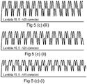
- Figures 5(a) to 5(c) (i) to (iii) each show images of spanwise cross sections of leading edges of an aerofoil in accordance with the present disclosure, as viewed from either the suction or pressure surface.
- the leading edge profile of each of figures 5(a) to 5(c) corresponds to the waveform in figures 4(a) to 4(c) respectively.
- the maximum amplitude of the resultant superimposed waveform (which corresponds to the maximum extent of the projections from the minimum chordal extent relative to the mean chord length, h max / c 0 ) corresponds to 0.1, 0.133 and 0.167 respectively.
- both the waveform and the maximum extent of the projections will have an impact both on the aerodynamics of the aerofoil, and the noise attenuation properties of the aerofoil.
- This repeating pattern of projections and recesses / troughs produces a leading edge profile comprising repeating at least first and second chordwise extending recesses having different extents relative to the mean chord line, separated in a spanwise direction by at least first and second generally chordwise extending projections having different extents relative to the mean chord line.
- the first recesses are separated by second recesses, such that alternating first and second recesses are provided.
- the leading edge profile shown in figure 4(b) also comprises a continuous forward and rearward sweeping curve extending in a direction extending from the root to the tip.
- the pattern comprises a first forward extending protrusion 150 extending a relatively large extent beyond from the mean chord line, followed by a relatively small first recess 152 such that the leading edge extends less than the mean chord line c 0 , followed by a relatively small second forward extending protrusion 154 extending forwardly of the mean chord line to a lesser extent than either the first recess 152 extends less than the mean chord line or the first protrusion extends forward of the mean chord line c 0 , followed by a small second recess 156 extending less than the mean chord line to the same extent that the second forward extending protrusion 150 extends beyond the mean chord line c 0 , followed by a 158 third forward protrusion extending forwardly of the mean chord line to a lesser extent than the first protrusion 150, but a greater extent than the second protrusion
- the leading edge profile of figure 4(b) comprises first, second and third projections, each having a different extent to one another and spaced from one another, and first, second and third recesses, which are similarly spaced in a spanwise direction and have different extents, i.e. their nadirs are spaced in a chordal direction.
- the leading edge profile shown in figure 5(c) defines a pair of forward extending protrusions 250, 254 extending a relatively large extent beyond from the mean chord line separated in a spanwise direction by a recess.
- the forward extending protrusions 250, 254 are followed by a pair of inwardly extending recesses 256, 260 which have an extent such that the leading edge extends less than the mean chord line to the same extent as the forward extending protrusions 250, 254 extend beyond the mean chord line c 0 .
- the leading edge profile then returns to the mean chord line c 0 , where the pattern is repeated.
- leading edge profile of figure 5(c) comprises first and second generally chordwise extending projections, with each first projection being spaced apart by two second projections.
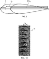
- Figure 9 shows a cross sectional view through the OGV 32 along the line A-A shown in figure 3 , and the line B-B shown in figure 3 , in each case the OGV 32 being sectioned along a line extending in a generally chordwise direction from the leading to the trailing edge.
- y is representative of the thickness of the aerofoil at chordwise position x and spanwise position r
- FIG. 9 This profile is illustrated in figure 9 (which is not drawn to scale), wherein the cross section A-A (shown in dotted lines) represents the region 0 ⁇ x,1, and the cross section B-B (shown in solid lines) represents the region 0 ⁇ x ⁇ 2/3c 0 .
- the first 2/3 of the chordal distance between the trailing edge and the mean chord line is defined by an NACA-65 series aerofoil profile (though it will be understood that other aerofoil profiles could be used).
- section B-B therefore, the cross-sectional shape corresponds entirely to the NACA-65 series aerofoil shape.
- chordal distance of this portion of the cross sectional profile is adjusted by a factor x/c(r). Consequently, the leading edge third of the chordal extent of the NACA-65 profile is transformed (i.e. "stretched") at different spanwise locations by a factor determined by the superimposed waveform, i.e. the chordal extent is linearly transformed by a factor 1/c(r).
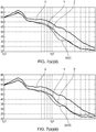
- Figures 6(a) (i) to 6(a) (iii) show the perceived noise (dB) of various leading edge profiles of various plates having otherwise similar dimensions, under similar conditions at an airflow velocity of 20 m/s.
- line X represents a flat plate having a straight leading edge.
- Line Y represents a plate having a leading edge comprising projections defined by a waveform composed of a single sinusoidal wave having a single wavelength relative to the mean chord distance of 0.033 ⁇ / c 0
- line Z represents a plate having a leading edge comprising projections defined by a waveform composed of a single sinusoidal wave having a single wavelength relative to the mean chord distance of 0.067 ⁇ / c 0 .
- Line (a)(i) represents a plate having the leading edge profile shown in figure 5(a)(i) .
- all of the flat plates having serrated leading edge profiles show a reduced noise profile across a wide range of frequencies from around 10 2 to 10 4 Hz, which represents the edge of normal human hearing.
- the double frequency leading edge profile plate shows a pronounced reduction in noise compared to the single frequency plates, particularly at frequencies around 10 3 Hz. Consequently, the disclosed aerofoil profile provides reduced aerodynamic noise in use.
- the recesses / troughs located between each projection at downstream positions in the in use flow direction produce tone noise out of phase with noise produced by recesses / toughs upstream. Consequently, the noise cancels out, reducing overall noise.
- This destructive interference effect is an additional noise reduction mechanism that is not present for single frequency serrations, leading to additional reductions in radiated noise from the aerofoil leading edge, which are additional to the reductions in noise provided by a serrated leading edge.
- first tone noise produced by the first recess is cancelled by the second recess
- different tone noise i.e. at a different frequency
- tone noise at a third frequency produced by the second recess is cancelled by the third recess, in view of the distance between the second and third recess, where tis is different to the distance between either the first and second recess, or the first and third recess. Consequently, such an arrangement may provide a wider broadband noise reduction compared to waveforms having only first and second chordally spaced recesses.
- line X again represents the flat plate having a straight leading edge.
- Line Y and Z represent plates having similar leading edge serrations to those of figure 6(a)(ii) , but with a maximum height relative to the mean chord distance h max / c 0 of 0.133.
- Line (a) represents a plate having the leading edge profile shown in figure 5(a)(ii) (i.e. having longer protrusions relative to those of figure 5(a)(ii) .
- the plate having a leading edge having double wavelength protrusions shows improved nose reduction performance.
- the noise reduction of the double wavelength protrusion leading edge compared to the straight and single wavelength protrusion leading edges is particularly pronounced at lower frequencies, peaking at around 700 Hz.
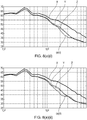
- Figure 7(a)(i) shows test results of the same leading edge profiles X, Y, Z, and (a)(i) of figure 6(i) , but with the airflow velocity increased to 40 m/s.
- the double wavelength leading edge protrusions again outperform the baseline and single wavelength leading edge protrusions in terms of noise attenuation.
- the relative reduction in noise occurs at higher frequencies, in this case, 1000 to 2000 Hz.
- Figures 7(a)(ii) and 7(a)(iii) show results from experiments on the same leading edge profiles as shown in figures 6(a)(ii) and 6(a)(iii) respectively, but again at 40 m/s. Again, in each case, the frequency spectrum of the relative noise reduction is altered. Consequently, it will be understood that the designer will select a protrusion length which best suits the noise profile at the typical in use airflow velocities likely to be encountered.
- Figure 8(a)(i) to 8(a)(iii) shows results from similar experiments as those shown in figure 6(i) to 6(iii) , but with the airflow velocity increased again to 60 m/s. Again, the sound attenuation spectrum is altered, in each case to a peak performance at around 3000 Hz. However, as can be seen in figure 8(iii) , the noise attenuation performance for double wavelength protrusions having a height h max / c 0 of 0.167 is inferior to that of single wavelength protrusions at higher frequencies, above around 3000 Hz. However, since these frequencies are perceived less by humans, this may be regarded as a good compromise.
- Figures 6(c)(ii) and 6b(iii) show experimental results for windtunnel tests at 20 m/s for a second set of flat plates.
- X represents a baseline plate
- 6(c)(ii) and 6b(iii) represent the plates shown in figures 5(c)(ii) and 5(c)(iii) respectively.
- the maximum amplitude of the first, second and (if present) further waveforms c j (r) that makeup the superpositioned waveform are the same. It has been found in experimentation that, by keeping the maximum amplitude of the waveforms c j (r) the same provides an enhanced noise reduction over a narrow frequency bandwidth.
- the disclosed leading edge serration waveform envisages superpositioned waveforms having different maximum amplitudes.
- the invention is not limited to the embodiments above-described and various modifications and improvements can be made without departing from the concepts described herein.
- the invention could be employed in aerofoils of different parts of a gas turbine engine, different parts of an aircraft, or in non-aviation applications, such as wind turbines, marine propellers, industrial cooling fans, and other aerofoils in which noise is a consideration.
- the invention has been found to be effective for a wide range of aerofoil cross sectional profiles, and also for flat plate aerofoils.
Landscapes
- Engineering & Computer Science (AREA)
- Mechanical Engineering (AREA)
- General Engineering & Computer Science (AREA)
- Physics & Mathematics (AREA)
- Fluid Mechanics (AREA)
- Structures Of Non-Positive Displacement Pumps (AREA)
Claims (11)
- Schaufelblattkomponente (32), die eine Betriebsvorderkante (38) und eine Hinterkante (40) definiert, wobei die Vorderkante ein Wellenformprofil definiert, wobei das Wellenformprofil c(r) sich in einer Spannweitenrichtung erstreckt und eine Überlagerung einer ersten Welle und einer zweiten Welle aufweist, wobei die erste und die zweite Welle unterschiedliche Wellenlängen (γ) haben, so dass das Wellenformprofil eine Vielzahl von ersten und zweiten sich im Allgemeinen in Profilsehnenrichtung erstreckenden Ausnehmungen (46a, 46b) definiert, die in der Spannweitenrichtung beabstandet sind und eine unterschiedliche Ausdehnung in der Profilsehnenrichtung haben, dadurch gekennzeichnet, dass das Wellenformprofil die Form c(r) =

- Komponente nach Anspruch 1, wobei eine oder mehrere erste Ausnehmungen (46a) von einer weiteren ersten Ausnehmung (46a) in einer Spannweitenrichtung durch eine oder mehrere zweite Ausnehmungen (46b) getrennt sind.
- Komponente nach Anspruch 1 oder Anspruch 2, wobei die erste und die zweite Welle im Wesentlichen die gleiche Amplitude haben.
- Komponente nach einem der vorhergehenden Ansprüche, wobei γ1/γ2 zwischen ½ und 2 beträgt.
- Komponente nach einem der vorhergehenden Ansprüche, wobei h/c 0 zwischen 1/10 und 1/6 beträgt.
- Komponente nach einem der vorhergehenden Ansprüche, wobei das Schaufelblattquerschnittsprofil des Schaufelblatts (32) über die Spannweite des Schaufelblatts gemäß folgender Formel variiert:

- Komponente nach einem der vorhergehenden Ansprüche, wobei die Schaufelblattkomponente (32) ein Schaufelblatt eines Gasturbinentriebwerks (10) aufweist.
- Komponente nach Anspruch 7, wobei die Schaufelblattkomponente eine Auslassleitschaufel (32) eines Gasturbinentriebwerks (10) aufweist.
- Gasturbinentriebwerk (10), aufweisend eine Schaufelblattkomponente (32) gemäß einem der vorhergehenden Ansprüche.
- Flugzeug, aufweisend ein Gasturbinentriebwerk (10) nach Anspruch 10.
- Verfahren zum Entwerfen einer Vorderkante (40) einer Schaufelblattkomponente (32), wobei das Verfahren folgende Schritte umfasst:Definieren einer ersten und einer zweiten Welle, wobei die erste Welle eine andere Wellenlänge als die zweite Welle hat, dadurch gekennzeichnet, dass das Verfahren ferner folgende Schritte umfasst:Überlagern der ersten und zweiten Welle, um eine überlagerte Wellenform der Form c(r) = C 0 + h 1

 Definieren einer Schaufelblattkomponente (32), die ein Profil von Vorderkante (40) hat, das die überlagerte Wellenform c(r) aufweist, so dass die Vorderkante eine Vielzahl von ersten und zweiten sich im Allgemeinen in Profilsehnenrichtung erstreckenden Ausnehmungen definiert, die in einer Spanweitenrichtung beabstandet sind und eine unterschiedliche Ausdehnung in der Profilsehnenrichtung haben.
Applications Claiming Priority (1)
| Application Number | Priority Date | Filing Date | Title |
|---|---|---|---|
| GBGB1512688.1A GB201512688D0 (en) | 2015-07-20 | 2015-07-20 | Aerofoil |
Publications (2)
| Publication Number | Publication Date |
|---|---|
| EP3121376A1 EP3121376A1 (de) | 2017-01-25 |
| EP3121376B1 true EP3121376B1 (de) | 2017-09-13 |
Family
ID=54013280
Family Applications (1)
| Application Number | Title | Priority Date | Filing Date |
|---|---|---|---|
| EP16179463.1A Active EP3121376B1 (de) | 2015-07-20 | 2016-07-14 | Tragflügel |
Country Status (3)
| Country | Link |
|---|---|
| US (1) | US10301942B2 (de) |
| EP (1) | EP3121376B1 (de) |
| GB (1) | GB201512688D0 (de) |
Cited By (1)
| Publication number | Priority date | Publication date | Assignee | Title |
|---|---|---|---|---|
| DE102021105226A1 (de) | 2020-03-10 | 2021-09-16 | Ebm-Papst Mulfingen Gmbh & Co. Kg | Ventilator und Ventilatorflügel |
Families Citing this family (11)
| Publication number | Priority date | Publication date | Assignee | Title |
|---|---|---|---|---|
| EP3181895A1 (de) * | 2015-12-17 | 2017-06-21 | LM WP Patent Holding A/S | Teilerplattenanordnung für gezahnte windturbinenschaufel |
| GB201707836D0 (en) * | 2017-05-16 | 2017-06-28 | Oscar Propulsion Ltd | Outlet guide vanes |
| US10829198B2 (en) * | 2017-06-21 | 2020-11-10 | The Boeing Company | Krueger flap apparatus and methods incorporating a bullnose having a contour variation along a spanwise direction |
| FR3078098B1 (fr) * | 2018-02-16 | 2020-06-19 | Safran Aircraft Engines | Structure a profil en serrations inclinees |
| FR3078101B1 (fr) * | 2018-02-16 | 2020-11-27 | Safran Aircraft Engines | Turbomachine a bec de separation de flux a profil en serrations |
| GB201809353D0 (en) * | 2018-06-07 | 2018-07-25 | Rolls Royce Plc | Aerofoil |
| GB201818839D0 (en) * | 2018-11-19 | 2019-01-02 | Cambridge Entpr Ltd | Foils with serrations |
| GB201906920D0 (en) | 2019-05-16 | 2019-07-03 | Univ Brunel | Method of reducing noise from an aerofoil |
| US11965425B2 (en) | 2022-05-31 | 2024-04-23 | General Electric Company | Airfoil for a turbofan engine |
| US12012898B2 (en) | 2022-11-03 | 2024-06-18 | General Electric Company | Gas turbine engine with acoustic spacing of the fan blades and outlet guide vanes |
| WO2024108302A1 (en) * | 2022-11-23 | 2024-05-30 | Biomerenewables Inc. | Structure with serrations adapted to traverse a fluid environment |
Family Cites Families (26)
| Publication number | Priority date | Publication date | Assignee | Title |
|---|---|---|---|---|
| GB1560683A (en) * | 1972-11-28 | 1980-02-06 | Rolls Royce | Turbine blade |
| IT1036993B (it) * | 1974-07-02 | 1979-10-30 | Rotron Inc | Dispositivo per il movimento di un fluido |
| US4720239A (en) * | 1982-10-22 | 1988-01-19 | Owczarek Jerzy A | Stator blades of turbomachines |
| US4830315A (en) * | 1986-04-30 | 1989-05-16 | United Technologies Corporation | Airfoil-shaped body |
| US5386955A (en) * | 1986-05-22 | 1995-02-07 | Rolls-Royce Plc | Control of fluid flow |
| US5088665A (en) * | 1989-10-31 | 1992-02-18 | The United States Of America As Represented By The Administrator Of The National Aeronautics And Space Administration | Serrated trailing edges for improving lift and drag characteristics of lifting surfaces |
| NL9301910A (nl) * | 1993-11-04 | 1995-06-01 | Stork Prod Eng | Windturbine. |
| US5642985A (en) * | 1995-11-17 | 1997-07-01 | United Technologies Corporation | Swept turbomachinery blade |
| US6431498B1 (en) | 2000-06-30 | 2002-08-13 | Philip Watts | Scalloped wing leading edge |
| US6733240B2 (en) * | 2001-07-18 | 2004-05-11 | General Electric Company | Serrated fan blade |
| EP2050929B1 (de) * | 2004-06-02 | 2009-10-21 | Rolls-Royce Deutschland Ltd & Co KG | Verdichterschaufel, insbesondere für den Fan von Flugzeugtriebwerken |
| JP4973249B2 (ja) * | 2006-03-31 | 2012-07-11 | ダイキン工業株式会社 | 多翼ファン |
| US8083487B2 (en) * | 2007-07-09 | 2011-12-27 | General Electric Company | Rotary airfoils and method for fabricating same |
| US20090074585A1 (en) * | 2007-09-19 | 2009-03-19 | General Electric Company | Wind turbine blades with trailing edge serrations |
| FR2937078B1 (fr) * | 2008-10-13 | 2011-09-23 | Snecma | Aube de turbine a performances aerodynamiques ameliorees. |
| KR101016010B1 (ko) | 2009-04-08 | 2011-02-23 | 건국대학교 산학협력단 | 회전익-와류-상호작용 소음 저감을 위한 가변돌기를 가진 회전익항공기용 회전익 |
| CN102803725B (zh) * | 2010-03-17 | 2016-08-10 | 森西勒Pat股份公司 | 微型泵 |
| WO2011157849A2 (en) * | 2010-06-18 | 2011-12-22 | Suzlon Blade Technology B.V. | Rotor blade for a wind turbine |
| GB201016455D0 (en) * | 2010-09-30 | 2010-11-17 | Imp Innovations Ltd | Fluid flow modification |
| US8460779B2 (en) * | 2011-03-30 | 2013-06-11 | General Electric Company | Microstructures for reducing noise of a fluid dynamic structure |
| US8414261B2 (en) * | 2011-05-31 | 2013-04-09 | General Electric Company | Noise reducer for rotor blade in wind turbine |
| US9341158B2 (en) * | 2011-12-08 | 2016-05-17 | Inventus Holdings, Llc | Quiet wind turbine blade |
| GB2497739A (en) * | 2011-12-19 | 2013-06-26 | Rolls Royce Plc | Rotor blade with serrated trailing edge |
| US9121294B2 (en) * | 2011-12-20 | 2015-09-01 | General Electric Company | Fan blade with composite core and wavy wall trailing edge cladding |
| US9249666B2 (en) * | 2011-12-22 | 2016-02-02 | General Electric Company | Airfoils for wake desensitization and method for fabricating same |
| KR101920085B1 (ko) * | 2012-09-12 | 2018-11-19 | 엘지전자 주식회사 | 팬 |
-
2015
- 2015-07-20 GB GBGB1512688.1A patent/GB201512688D0/en not_active Ceased
-
2016
- 2016-07-14 EP EP16179463.1A patent/EP3121376B1/de active Active
- 2016-07-15 US US15/211,306 patent/US10301942B2/en active Active
Non-Patent Citations (1)
| Title |
|---|
| None * |
Cited By (7)
| Publication number | Priority date | Publication date | Assignee | Title |
|---|---|---|---|---|
| DE102021105226A1 (de) | 2020-03-10 | 2021-09-16 | Ebm-Papst Mulfingen Gmbh & Co. Kg | Ventilator und Ventilatorflügel |
| WO2021180559A1 (de) | 2020-03-10 | 2021-09-16 | Ebm-Papst Mulfingen Gmbh & Co. Kg | Ventilator und ventilatorflügel |
| DE102021105225A1 (de) | 2020-03-10 | 2021-09-16 | Ebm-Papst Mulfingen Gmbh & Co. Kg | Ventilator und Ventilatorflügel |
| WO2021180560A1 (de) | 2020-03-10 | 2021-09-16 | Ebm-Papst Mulfingen Gmbh & Co. Kg | Ventilator und ventilatorflügel |
| EP4083433A1 (de) | 2020-03-10 | 2022-11-02 | ebm-papst Mulfingen GmbH & Co. KG | Ventilator und ventilatorflügel |
| EP4083432A1 (de) | 2020-03-10 | 2022-11-02 | ebm-papst Mulfingen GmbH & Co. KG | Ventilator und ventilatorflügel |
| US11965521B2 (en) | 2020-03-10 | 2024-04-23 | Ebm-Papst Mulfingen Gmbh & Co. Kg | Fan and fan blades |
Also Published As
| Publication number | Publication date |
|---|---|
| US10301942B2 (en) | 2019-05-28 |
| US20170022820A1 (en) | 2017-01-26 |
| EP3121376A1 (de) | 2017-01-25 |
| GB201512688D0 (en) | 2015-08-26 |
Similar Documents
| Publication | Publication Date | Title |
|---|---|---|
| EP3121376B1 (de) | Tragflügel | |
| EP3208420B1 (de) | Schaufelblatt | |
| US11136109B2 (en) | Airfoil for a rotary machine including a propellor assembly | |
| JP4130337B2 (ja) | 鋸歯状部をもつファンブレード | |
| EP2014870B1 (de) | Schaufel zur Verwendung in einer Rotationsmaschine | |
| US11859534B2 (en) | Profiled structure and associated turbomachine | |
| EP2350439B1 (de) | Verfahren zur Optimierung der Form eines Schaufelprofils und zugehöriges Schaufelprofil | |
| US20210039767A1 (en) | Aerofoil | |
| CN113573978B (zh) | 翼型、降噪装置、涡轮机、飞行器、水运工具与冷却风扇 | |
| EP3379030B1 (de) | Fanrotor mit kontrolle der strömungsinduzierten resonanz | |
| EP3002210B1 (de) | Triebwerksgondel | |
| EP3379029A1 (de) | Fanrotor mit kontrolle der strömungsinduzierten resonanz | |
| US11105344B2 (en) | Aerofoil | |
| EP3480427B1 (de) | Tragflügel | |
| US11808246B2 (en) | Method for forming an add-on component for an aerofoil | |
| US11525365B2 (en) | Turbomachine with serrated-profile flow-splitter nose | |
| EP0233501B1 (de) | Ausbildung von im Zustrom zu Luftschrauben, Mantelschrauben und/oder Fans liegenden Bauteilen zur Verringerung des von ihnen verursachten Zusatzlärms sowie zur Verringerung der Wechselbelastung der Propellerblätter | |
| EP2818637B1 (de) | Gasturbinenbauteil zum Ausfluss einer Kühlströmung in eine Umgebung mit periodischen Druckschwankungen | |
| EP2733071A2 (de) | Rotorblatt | |
| Metzger et al. | Benefits of blade sweep for advanced turboprops | |
| CN110536833B (zh) | 衰减螺旋桨尾流声学相互作用的下游表面特征 | |
| Woodhead et al. | On the double-rooted trailing edge serration | |
| CN114856712B (zh) | 一种具有仿生叶顶的叶片及设有该叶片的开式转子 | |
| US20240059396A1 (en) | Improved acoustic attenuation device for an aircraft propulsion unit | |
| CN118076802A (zh) | 用于航空推进器的具有锯齿件的出口喷嘴 |
Legal Events
| Date | Code | Title | Description |
|---|---|---|---|
| PUAI | Public reference made under article 153(3) epc to a published international application that has entered the european phase |
Free format text: ORIGINAL CODE: 0009012 |
|
| STAA | Information on the status of an ep patent application or granted ep patent |
Free format text: STATUS: THE APPLICATION HAS BEEN PUBLISHED |
|
| AK | Designated contracting states |
Kind code of ref document: A1 Designated state(s): AL AT BE BG CH CY CZ DE DK EE ES FI FR GB GR HR HU IE IS IT LI LT LU LV MC MK MT NL NO PL PT RO RS SE SI SK SM TR |
|
| AX | Request for extension of the european patent |
Extension state: BA ME |
|
| STAA | Information on the status of an ep patent application or granted ep patent |
Free format text: STATUS: REQUEST FOR EXAMINATION WAS MADE |
|
| 17P | Request for examination filed |
Effective date: 20170215 |
|
| RBV | Designated contracting states (corrected) |
Designated state(s): AL AT BE BG CH CY CZ DE DK EE ES FI FR GB GR HR HU IE IS IT LI LT LU LV MC MK MT NL NO PL PT RO RS SE SI SK SM TR |
|
| GRAP | Despatch of communication of intention to grant a patent |
Free format text: ORIGINAL CODE: EPIDOSNIGR1 |
|
| STAA | Information on the status of an ep patent application or granted ep patent |
Free format text: STATUS: GRANT OF PATENT IS INTENDED |
|
| INTG | Intention to grant announced |
Effective date: 20170616 |
|
| GRAS | Grant fee paid |
Free format text: ORIGINAL CODE: EPIDOSNIGR3 |
|
| GRAA | (expected) grant |
Free format text: ORIGINAL CODE: 0009210 |
|
| STAA | Information on the status of an ep patent application or granted ep patent |
Free format text: STATUS: THE PATENT HAS BEEN GRANTED |
|
| AK | Designated contracting states |
Kind code of ref document: B1 Designated state(s): AL AT BE BG CH CY CZ DE DK EE ES FI FR GB GR HR HU IE IS IT LI LT LU LV MC MK MT NL NO PL PT RO RS SE SI SK SM TR |
|
| REG | Reference to a national code |
Ref country code: GB Ref legal event code: FG4D |
|
| REG | Reference to a national code |
Ref country code: CH Ref legal event code: EP |
|
| REG | Reference to a national code |
Ref country code: IE Ref legal event code: FG4D |
|
| REG | Reference to a national code |
Ref country code: AT Ref legal event code: REF Ref document number: 928367 Country of ref document: AT Kind code of ref document: T Effective date: 20171015 |
|
| REG | Reference to a national code |
Ref country code: DE Ref legal event code: R096 Ref document number: 602016000391 Country of ref document: DE |
|
| REG | Reference to a national code |
Ref country code: NL Ref legal event code: MP Effective date: 20170913 |
|
| REG | Reference to a national code |
Ref country code: LT Ref legal event code: MG4D |
|
| PG25 | Lapsed in a contracting state [announced via postgrant information from national office to epo] |
Ref country code: NO Free format text: LAPSE BECAUSE OF FAILURE TO SUBMIT A TRANSLATION OF THE DESCRIPTION OR TO PAY THE FEE WITHIN THE PRESCRIBED TIME-LIMIT Effective date: 20171213 Ref country code: SE Free format text: LAPSE BECAUSE OF FAILURE TO SUBMIT A TRANSLATION OF THE DESCRIPTION OR TO PAY THE FEE WITHIN THE PRESCRIBED TIME-LIMIT Effective date: 20170913 Ref country code: FI Free format text: LAPSE BECAUSE OF FAILURE TO SUBMIT A TRANSLATION OF THE DESCRIPTION OR TO PAY THE FEE WITHIN THE PRESCRIBED TIME-LIMIT Effective date: 20170913 Ref country code: HR Free format text: LAPSE BECAUSE OF FAILURE TO SUBMIT A TRANSLATION OF THE DESCRIPTION OR TO PAY THE FEE WITHIN THE PRESCRIBED TIME-LIMIT Effective date: 20170913 Ref country code: LT Free format text: LAPSE BECAUSE OF FAILURE TO SUBMIT A TRANSLATION OF THE DESCRIPTION OR TO PAY THE FEE WITHIN THE PRESCRIBED TIME-LIMIT Effective date: 20170913 |
|
| REG | Reference to a national code |
Ref country code: AT Ref legal event code: MK05 Ref document number: 928367 Country of ref document: AT Kind code of ref document: T Effective date: 20170913 |
|
| PG25 | Lapsed in a contracting state [announced via postgrant information from national office to epo] |
Ref country code: LV Free format text: LAPSE BECAUSE OF FAILURE TO SUBMIT A TRANSLATION OF THE DESCRIPTION OR TO PAY THE FEE WITHIN THE PRESCRIBED TIME-LIMIT Effective date: 20170913 Ref country code: ES Free format text: LAPSE BECAUSE OF FAILURE TO SUBMIT A TRANSLATION OF THE DESCRIPTION OR TO PAY THE FEE WITHIN THE PRESCRIBED TIME-LIMIT Effective date: 20170913 Ref country code: BG Free format text: LAPSE BECAUSE OF FAILURE TO SUBMIT A TRANSLATION OF THE DESCRIPTION OR TO PAY THE FEE WITHIN THE PRESCRIBED TIME-LIMIT Effective date: 20171213 Ref country code: RS Free format text: LAPSE BECAUSE OF FAILURE TO SUBMIT A TRANSLATION OF THE DESCRIPTION OR TO PAY THE FEE WITHIN THE PRESCRIBED TIME-LIMIT Effective date: 20170913 Ref country code: GR Free format text: LAPSE BECAUSE OF FAILURE TO SUBMIT A TRANSLATION OF THE DESCRIPTION OR TO PAY THE FEE WITHIN THE PRESCRIBED TIME-LIMIT Effective date: 20171214 |
|
| PG25 | Lapsed in a contracting state [announced via postgrant information from national office to epo] |
Ref country code: NL Free format text: LAPSE BECAUSE OF FAILURE TO SUBMIT A TRANSLATION OF THE DESCRIPTION OR TO PAY THE FEE WITHIN THE PRESCRIBED TIME-LIMIT Effective date: 20170913 |
|
| PG25 | Lapsed in a contracting state [announced via postgrant information from national office to epo] |
Ref country code: PL Free format text: LAPSE BECAUSE OF FAILURE TO SUBMIT A TRANSLATION OF THE DESCRIPTION OR TO PAY THE FEE WITHIN THE PRESCRIBED TIME-LIMIT Effective date: 20170913 Ref country code: CZ Free format text: LAPSE BECAUSE OF FAILURE TO SUBMIT A TRANSLATION OF THE DESCRIPTION OR TO PAY THE FEE WITHIN THE PRESCRIBED TIME-LIMIT Effective date: 20170913 |
|
| PG25 | Lapsed in a contracting state [announced via postgrant information from national office to epo] |
Ref country code: SM Free format text: LAPSE BECAUSE OF FAILURE TO SUBMIT A TRANSLATION OF THE DESCRIPTION OR TO PAY THE FEE WITHIN THE PRESCRIBED TIME-LIMIT Effective date: 20170913 Ref country code: EE Free format text: LAPSE BECAUSE OF FAILURE TO SUBMIT A TRANSLATION OF THE DESCRIPTION OR TO PAY THE FEE WITHIN THE PRESCRIBED TIME-LIMIT Effective date: 20170913 Ref country code: IS Free format text: LAPSE BECAUSE OF FAILURE TO SUBMIT A TRANSLATION OF THE DESCRIPTION OR TO PAY THE FEE WITHIN THE PRESCRIBED TIME-LIMIT Effective date: 20180113 Ref country code: SK Free format text: LAPSE BECAUSE OF FAILURE TO SUBMIT A TRANSLATION OF THE DESCRIPTION OR TO PAY THE FEE WITHIN THE PRESCRIBED TIME-LIMIT Effective date: 20170913 Ref country code: IT Free format text: LAPSE BECAUSE OF FAILURE TO SUBMIT A TRANSLATION OF THE DESCRIPTION OR TO PAY THE FEE WITHIN THE PRESCRIBED TIME-LIMIT Effective date: 20170913 Ref country code: AT Free format text: LAPSE BECAUSE OF FAILURE TO SUBMIT A TRANSLATION OF THE DESCRIPTION OR TO PAY THE FEE WITHIN THE PRESCRIBED TIME-LIMIT Effective date: 20170913 |
|
| REG | Reference to a national code |
Ref country code: DE Ref legal event code: R097 Ref document number: 602016000391 Country of ref document: DE |
|
| PLBE | No opposition filed within time limit |
Free format text: ORIGINAL CODE: 0009261 |
|
| STAA | Information on the status of an ep patent application or granted ep patent |
Free format text: STATUS: NO OPPOSITION FILED WITHIN TIME LIMIT |
|
| REG | Reference to a national code |
Ref country code: FR Ref legal event code: PLFP Year of fee payment: 3 |
|
| PG25 | Lapsed in a contracting state [announced via postgrant information from national office to epo] |
Ref country code: DK Free format text: LAPSE BECAUSE OF FAILURE TO SUBMIT A TRANSLATION OF THE DESCRIPTION OR TO PAY THE FEE WITHIN THE PRESCRIBED TIME-LIMIT Effective date: 20170913 |
|
| 26N | No opposition filed |
Effective date: 20180614 |
|
| PG25 | Lapsed in a contracting state [announced via postgrant information from national office to epo] |
Ref country code: LU Free format text: LAPSE BECAUSE OF NON-PAYMENT OF DUE FEES Effective date: 20180714 Ref country code: MC Free format text: LAPSE BECAUSE OF FAILURE TO SUBMIT A TRANSLATION OF THE DESCRIPTION OR TO PAY THE FEE WITHIN THE PRESCRIBED TIME-LIMIT Effective date: 20170913 |
|
| REG | Reference to a national code |
Ref country code: BE Ref legal event code: MM Effective date: 20180731 |
|
| REG | Reference to a national code |
Ref country code: IE Ref legal event code: MM4A |
|
| PG25 | Lapsed in a contracting state [announced via postgrant information from national office to epo] |
Ref country code: IE Free format text: LAPSE BECAUSE OF NON-PAYMENT OF DUE FEES Effective date: 20180714 |
|
| PG25 | Lapsed in a contracting state [announced via postgrant information from national office to epo] |
Ref country code: BE Free format text: LAPSE BECAUSE OF NON-PAYMENT OF DUE FEES Effective date: 20180731 |
|
| PG25 | Lapsed in a contracting state [announced via postgrant information from national office to epo] |
Ref country code: MT Free format text: LAPSE BECAUSE OF NON-PAYMENT OF DUE FEES Effective date: 20180714 |
|
| REG | Reference to a national code |
Ref country code: CH Ref legal event code: PL |
|
| PG25 | Lapsed in a contracting state [announced via postgrant information from national office to epo] |
Ref country code: TR Free format text: LAPSE BECAUSE OF FAILURE TO SUBMIT A TRANSLATION OF THE DESCRIPTION OR TO PAY THE FEE WITHIN THE PRESCRIBED TIME-LIMIT Effective date: 20170913 |
|
| PG25 | Lapsed in a contracting state [announced via postgrant information from national office to epo] |
Ref country code: CH Free format text: LAPSE BECAUSE OF NON-PAYMENT OF DUE FEES Effective date: 20190731 Ref country code: LI Free format text: LAPSE BECAUSE OF NON-PAYMENT OF DUE FEES Effective date: 20190731 Ref country code: PT Free format text: LAPSE BECAUSE OF FAILURE TO SUBMIT A TRANSLATION OF THE DESCRIPTION OR TO PAY THE FEE WITHIN THE PRESCRIBED TIME-LIMIT Effective date: 20170913 |
|
| PG25 | Lapsed in a contracting state [announced via postgrant information from national office to epo] |
Ref country code: MK Free format text: LAPSE BECAUSE OF NON-PAYMENT OF DUE FEES Effective date: 20170913 Ref country code: RO Free format text: LAPSE BECAUSE OF FAILURE TO SUBMIT A TRANSLATION OF THE DESCRIPTION OR TO PAY THE FEE WITHIN THE PRESCRIBED TIME-LIMIT Effective date: 20170913 Ref country code: CY Free format text: LAPSE BECAUSE OF FAILURE TO SUBMIT A TRANSLATION OF THE DESCRIPTION OR TO PAY THE FEE WITHIN THE PRESCRIBED TIME-LIMIT Effective date: 20170913 Ref country code: HU Free format text: LAPSE BECAUSE OF FAILURE TO SUBMIT A TRANSLATION OF THE DESCRIPTION OR TO PAY THE FEE WITHIN THE PRESCRIBED TIME-LIMIT; INVALID AB INITIO Effective date: 20160714 |
|
| PG25 | Lapsed in a contracting state [announced via postgrant information from national office to epo] |
Ref country code: AL Free format text: LAPSE BECAUSE OF FAILURE TO SUBMIT A TRANSLATION OF THE DESCRIPTION OR TO PAY THE FEE WITHIN THE PRESCRIBED TIME-LIMIT Effective date: 20170913 |
|
| PG25 | Lapsed in a contracting state [announced via postgrant information from national office to epo] |
Ref country code: SI Free format text: LAPSE BECAUSE OF NON-PAYMENT OF DUE FEES Effective date: 20180714 |
|
| P01 | Opt-out of the competence of the unified patent court (upc) registered |
Effective date: 20230528 |
|
| PGFP | Annual fee paid to national office [announced via postgrant information from national office to epo] |
Ref country code: GB Payment date: 20230725 Year of fee payment: 8 |
|
| PGFP | Annual fee paid to national office [announced via postgrant information from national office to epo] |
Ref country code: FR Payment date: 20230725 Year of fee payment: 8 Ref country code: DE Payment date: 20230726 Year of fee payment: 8 |