EP3121363B1 - Befestigungswinkel für rahmen mit profilen - Google Patents
Befestigungswinkel für rahmen mit profilen Download PDFInfo
- Publication number
- EP3121363B1 EP3121363B1 EP16178732.0A EP16178732A EP3121363B1 EP 3121363 B1 EP3121363 B1 EP 3121363B1 EP 16178732 A EP16178732 A EP 16178732A EP 3121363 B1 EP3121363 B1 EP 3121363B1
- Authority
- EP
- European Patent Office
- Prior art keywords
- profile
- wing
- shaped groove
- frame
- width
- Prior art date
- Legal status (The legal status is an assumption and is not a legal conclusion. Google has not performed a legal analysis and makes no representation as to the accuracy of the status listed.)
- Active
Links
- 238000010079 rubber tapping Methods 0.000 claims description 2
- 239000011521 glass Substances 0.000 description 6
- 230000000903 blocking effect Effects 0.000 description 1
- 230000001419 dependent effect Effects 0.000 description 1
- 238000005553 drilling Methods 0.000 description 1
- 238000003780 insertion Methods 0.000 description 1
- 230000037431 insertion Effects 0.000 description 1
Images


Classifications
-
- E—FIXED CONSTRUCTIONS
- E06—DOORS, WINDOWS, SHUTTERS, OR ROLLER BLINDS IN GENERAL; LADDERS
- E06B—FIXED OR MOVABLE CLOSURES FOR OPENINGS IN BUILDINGS, VEHICLES, FENCES OR LIKE ENCLOSURES IN GENERAL, e.g. DOORS, WINDOWS, BLINDS, GATES
- E06B3/00—Window sashes, door leaves, or like elements for closing wall or like openings; Layout of fixed or moving closures, e.g. windows in wall or like openings; Features of rigidly-mounted outer frames relating to the mounting of wing frames
- E06B3/96—Corner joints or edge joints for windows, doors, or the like frames or wings
- E06B3/964—Corner joints or edge joints for windows, doors, or the like frames or wings using separate connection pieces, e.g. T-connection pieces
- E06B3/9642—Butt type joints with at least one frame member cut off square; T-shape joints
-
- E—FIXED CONSTRUCTIONS
- E06—DOORS, WINDOWS, SHUTTERS, OR ROLLER BLINDS IN GENERAL; LADDERS
- E06B—FIXED OR MOVABLE CLOSURES FOR OPENINGS IN BUILDINGS, VEHICLES, FENCES OR LIKE ENCLOSURES IN GENERAL, e.g. DOORS, WINDOWS, BLINDS, GATES
- E06B3/00—Window sashes, door leaves, or like elements for closing wall or like openings; Layout of fixed or moving closures, e.g. windows in wall or like openings; Features of rigidly-mounted outer frames relating to the mounting of wing frames
- E06B3/96—Corner joints or edge joints for windows, doors, or the like frames or wings
- E06B3/964—Corner joints or edge joints for windows, doors, or the like frames or wings using separate connection pieces, e.g. T-connection pieces
- E06B3/968—Corner joints or edge joints for windows, doors, or the like frames or wings using separate connection pieces, e.g. T-connection pieces characterised by the way the connecting pieces are fixed in or on the frame members
- E06B3/972—Corner joints or edge joints for windows, doors, or the like frames or wings using separate connection pieces, e.g. T-connection pieces characterised by the way the connecting pieces are fixed in or on the frame members by increasing the cross-section of the connecting pieces, e.g. by expanding the connecting pieces with wedges
-
- E—FIXED CONSTRUCTIONS
- E06—DOORS, WINDOWS, SHUTTERS, OR ROLLER BLINDS IN GENERAL; LADDERS
- E06B—FIXED OR MOVABLE CLOSURES FOR OPENINGS IN BUILDINGS, VEHICLES, FENCES OR LIKE ENCLOSURES IN GENERAL, e.g. DOORS, WINDOWS, BLINDS, GATES
- E06B3/00—Window sashes, door leaves, or like elements for closing wall or like openings; Layout of fixed or moving closures, e.g. windows in wall or like openings; Features of rigidly-mounted outer frames relating to the mounting of wing frames
- E06B3/96—Corner joints or edge joints for windows, doors, or the like frames or wings
- E06B3/988—Corner joints or edge joints for windows, doors, or the like frames or wings specially adapted for sheet metal frame members with an open U-shaped cross-section
Definitions
- the present patent application for industrial invention relates to a fixing square for frame comprising profiles inserted in the square channel.
- the invention relates to the sector of fixing means for door and window frames, i.e. for architectural elements realized to close the openings obtained in masonry walls.
- the fixing square that is the object of the present invention is used to connect two profiles of a frame disposed in such manner to form a "T", to which two glass-stops are fitted; said fixing square comprises two plates in orthogonal position, each plate being intended to be inserted inside a profile.
- T-shaped frames for door and window are composed of two profiles, each profile comprising an external lateral surface and a “T"-longitudinal groove provided on said external lateral surface; said "T"-shaped groove comprises a rectangular base housing and a reduced longitudinal opening.
- said groove is axially accessible through two axial openings, each of them being disposed in proximal position to the free end section of the profile.
- Said end section of the profile is intended to be stopped against the external lateral surface of the other profile, in correspondence of the "T"-shaped groove of the latter profile in such manner that said two grooves are aligned.
- the "T"-shaped frame comprises a fixing square, which comprises a first wing and a second wing, which are perpendicular and have the same width and height as the base housing of the "T"-shaped groove of the profiles.
- each wing is such to position the wing inside the base housing of the "T"-shaped groove of the corresponding profile, being axially inserted inside said base housing and crossing one of the two axial openings of the "T"-shaped groove.
- the mounting of a "T"-shaped frame provides for axially inserting a wing of the fixing square in the "T"-shaped groove, making said fixing square slide until it reaches the desired position; successively, the other wing of the fixing screw is inserted in the axial opening of the "T"-shaped groove provided on the other profile.
- the insertion of the fixing square must occur before the profiles are in the final position, because when the first profile is positioned perpendicularly to the second profile, with its free end section stopped against the lateral surface of the second profile, the latter indirectly covers the axial opening of the first profile.
- the "T"-shaped grooves of said profiles are intended to act as fixing housings for devices, commonly known as glass-stop, each of them being intended to be fitted to a "T"-shaped groove of a profile in order to obtain a stop edge for a glass positioned in the window or door frame.
- said glass-stop device (hereinafter simply defined as “glass-stop”) comprises elastic tabs that are fitted on the edges of the opening of the "T"-shaped groove of a profile and extend inside the "T"-shaped groove.
- the glass-stop fitted to the first profile and the glass-stop fitted to the second profile need to be stopped one against the other in such manner to be positioned orthogonally and uninterruptedly one after the other; more precisely, in case of a quadrangular glass, said glass is supported by a perimeter frame composed of four profiles that are mounted perpendicularly and consecutively, with the four edges of the glass stopped against said four profiles; in such a case the glass is kept in the chosen position by means of a frame composed of four consecutive perpendicular glass-stops, each of them being fixed on the side of the corresponding profile facing towards the glass.
- DE202013009756 discloses a fixing square intended to connect two profiles of a frame and comprising two wings, each wing being provided with an eccentric locking means configured in such manner to let the total width of the wing increase.
- US3375029 discloses a frame comprising two profiles and one fixing square disposed between said two profiles.
- the main purpose of the present invention is to overcome the aforementioned drawbacks of the prior art by disclosing a fixing square that simplifies the mounting, dismounting and blocking operations.
- Another purpose is to disclose a fixing square that, in addition to satisfying the aforementioned purpose, allows for fitting two glass-stops to two profiles connected by said fixing square and positioning said glass-stops in consecutive adjacent position in such manner that they are stopped and positioned uninterruptedly, one after the other, in correspondence of the fixing square.
- the frame of the invention comprises:
- the peculiarity of the frame consists in the fact that at least one wing of the fixing square has a lower width than the longitudinal opening of the "T"-shaped groove wherein it is inserted.
- Said at least one wing of the fixing square comprises an eccentric locking means configured in such manner to let the total length of the wing increase until a width at least equal to the width of the base housing wherein the wing is inserted.
- the advantage obtained by reducing the width of the wings of the fixing square and by inserting the eccentric locking means is the simplification of the mounting operations of the profiles and of the fixing square, inserting said wings into the longitudinal openings of the "T"-shaped grooves of the profiles, and then actuating the fixing means that, by increasing the total width of the wing, prevents the wing from moving inside the base housing of the groove or from coming out backwards through the axial opening.
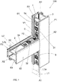
- the frame (100) of the invention comprises a first profile (P1) and a second profile (P2) connected to the first profile (P1).
- the first profile (P1) has a "T"-shaped longitudinal groove (S1) provided on one external lateral surface (B1).
- Such "T"-shaped groove (S1) of the first profile (P1) is sectionally provided with a base housing (1) having a width (L1) and a longitudinal opening (1a) with width (L1a).
- the second profile (P2) has a first "T"-shaped longitudinal groove (S2) obtained on one external lateral surface (B2).
- Such first "T"-shaped groove (S1) of the second profile (P2) is sectionally provided with a base housing (2) having a width (L2) and a longitudinal opening (2a) with width (L2a).
- the second profile (P2) has an end section (C) where the first "T"-shaped groove (S2) of the second profile (P2) ends.
- Such end section (C) is stopped against the external lateral surface (B1) of the first profile (P1) in correspondence of the "T"-shaped groove (S1) of the first profile (P1), in such manner that the "T"-shaped groove of the first profile (P1) and the first "T”-shaped groove of the second profile (P2) are mutually aligned.
- the second profile (P2) has a second "T"-shaped longitudinal groove (S3) provided on the external lateral surface (B2) in opposite position to the first "T"-shaped groove (S2) of the second profile (P2).
- Such second "T"-shaped groove (S3) of the second profile ends on the end section (C) of the second profile.
- the second "T"-shaped groove (S3) of the second profile (P2) and the “T"-shaped groove (S1) of the first profile (P1) are mutually aligned.
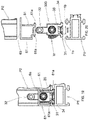
- a first embodiment of a fixing square (3) disposed between the two profiles (P1, P2) is disclosed.
- the fixing square (3) comprises a first wing (31) and a second wing (32) that are mutually inclined.
- the first wing (31) of the fixing square (3) is disposed inside the base housing (1) of the "T"-shaped groove (S1) of the first profile (P1).
- the second wing (32) of the fixing square (3) is disposed inside the base housing (2) of the first "T"-shaped groove (S2) of the second profile (P2).
- the first profile (P1) has a longitudinal axis (A1) that is orthogonal to the longitudinal axis (A2) of the first profile and the two wings (31, 32) of the fixing square (3) are mutually orthogonal.
- Each wing (31, 32) of the fixing square (3) has an internal side (FI) facing towards the profile (P1, P2) and an external side (FE) opposite to the internal side (FI).
- Each wing (31, 32) of the fixing square (3) has a width (L31, L32) lower than the width (L1a, L2a) of the longitudinal opening (1a, 2a) of the "T"-shaped groove (S1, S2) wherein it is inserted.
- the frame (100) comprises a second fixing square (3) inserted in the second "T"-shaped groove (S3) of the second profile (P2) and in the "T"-shaped groove (S1) of the first profile (P1).
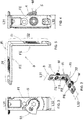
- each wing (31, 32) of the fixing square (3) comprises an eccentric locking means (M) that consists in a screw inserted in a hole provided on the wing (31, 32).
- Such eccentric locking means (M) is shaped in such a way to let the total width of the wing (31, 32) increase until it reaches a width at least equal to the width (L1, L2) of the base housing (1, 2) where the wing (31, 32) of the fixing square (3) is inserted.
- the screw of the eccentric locking means (M) comprises a head (4) disposed in correspondence of the external side (FE) of the wing (31, 32), preferably flush with said external side (FE). Moreover, such screw comprises a stem joined with the head (4) and an eccentric plate (5) fixed to an end of the stem and flush to the internal side (FI) of the wing (31, 32).
- Such eccentric plate (5) can be in an idle position, wherein it does not protrude laterally from the wing (31, 32), and in an operating position, wherein it protrudes laterally from the wing (31, 32), as shown in Figs. 2, 3 and 4 .
- the eccentric plate (5) has a knurled free edge (51) that interferes with the walls of the base housing (1, 2) of the groove (S, S2, S3) inside which the wing (31, 32) is disposed.
- the two wings (31, 32) of the fixing square have a hole (F1, F2) and the frame (100) advantageously comprises a self-drilling and self-tapping screw (V1) inserted in the hole (F1, F2) and screwed on the profile (P1, P2).
- V1 self-drilling and self-tapping screw
- the head of said screw (V1) is tapered, just like the hole (F1, F2) that houses the screw (V1).
- the holes (F1, F2) of the wings (31, 32) of the fixing square (3) are elongated and have a longitudinal axis that is parallel or coinciding with the wing.
- the fixing square of the invention can be also adjusted to frames with other configurations, such as cross frame, "Z"-shaped frames, "X"-shaped frames, etc.
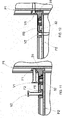
- a second embodiment of the fixing square (300) is disclosed, wherein the eccentric locking means (M) is mounted only on the second wing (32) of the fixing square (300).
- the first wing (31) of the fixing square comprises a portion (34) with increased width and a portion (35) with reduced width.
- the increased portion (34) and the reduced portion (35) protrude in opposite directions from the first wing (31) of the fixing square (300).
- the first wing (31) of the fixing square (300) has a longitudinal axis (D-D).
- the increased portion (34) is shaped as a rectangular plate and is provided with a pair of parallel long sides (36), a pair of parallel short sides (37) and a thickness (H34), as indicated in Figs. 8 and 9 .
- the short sides (37) have a length (L37).
- the increased portion (34) has a higher width (W34) than the width (L32) of the second wing (32) and is identical to the width (L1) of the "T"-shaped groove (S1) of the first profile (P1) wherein it is inserted.
- the reduced portion (35) has a lower width (W35) than the width (W34) of the increased portion (34).
- the thickness (H34) of the increased portion (34) has a value that is identical to or lower than the depth (H1) of the "T"-shaped groove (S1) of the first profile (P1) wherein it is inserted.
- the pair of parallel long sides (36) comprises a long front side (36a) from which the reduced portion (35) protrudes, and a long back side (36b) facing the side opposite to the reduced portion (35).
- the long front side (36a) is coplanar to the external side (FE) of the second wing (32).
- the reduced portion (35) has a pair of parallel sides (38), which are perpendicular to the long front side (36a).
- the parallel sides have a length (L38).
- the total length (L31) is obtained from adding the length (L38) of the parallel sides (38) of the reduced portion (35) with the length (L37) of the short parallel sides (37) of the increased portion (34).
- the total length (L31) of the first wing (31) is lower than the width (L1a) of the opening (1a) of the "T"-shaped groove (S1) of the first profile (P1) wherein said first wing (31) is inserted.
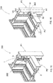
- the increased portion (34) of the first wing (31) of the fixing square (300) comprises a lateral rounded edge (39) in order to let the fixing square (300) rotate inside the "T"-shaped groove (S1) of the first profile (P1), as shown in Fig. 14 .
- the rotation of the fixing square provides that the fixing square (300) goes from a position wherein the longitudinal axis (D-D) of the first wing (31) is transverse with respect to the longitudinal axis (A1-A1) of the first profile (P1), to a position (see Fig. 15 ) wherein the longitudinal axis (D-D) of the first wing (31) is parallel to the longitudinal axis (A1-A1) of the first profile (P1) and the internal side (FI) of the second wing (32) of the fixing square (300) is faced towards the base housing (2) of the first "T"-shaped groove (S2) of the second profile (P2).
- the frame (100) comprises a first glass-stop (6a) fixed to the first profile (P1) and a second glass-stop (6b) fixed to the second profile (P2).
- each glass-stop (6a, 6b) comprises:
- a transverse end section (62) of the first glass-stop (6a) is stopped against the second profile (P2), whereas the transverse end section (62) of the second glass-stop (6b) is stopped against the main wall (63) of the first glass-stop (6a).
- the reduced portion (35) of the first wing (31) of the fixing square (300) is disposed between the tabs (61).
- the reduced portion (35) of the first wing (31) of the fixing square (300) has a lower width (W35) than the internal distance (W61a) between the hook-shaped end sections (61a) of the tabs (61) of the glass-stop (6a, 6b), as shown in Fig. 20 .
- the second wing (32) of the fixing square (300) has a lower width (L32) than the width (L2a) of the longitudinal opening (2a) of the first "T"-shaped groove (S2) of the second profile (P2) wherein it is inserted.
- the fixing square (300) is prevented from coming out from the base housing (1) of the "T"-shaped groove (S2) of the first profile (P1).
- the first glass-stop (6a) can be inserted in the first profile (P1) and positioned in such manner that said first glass-stop (6a) is stopped against the second profile (P2).
- the second glass-stop (6b) can be inserted in the second profile and stopped against the main wall (63) of the first glass-stop (6a).
- the glass-stops (6a, 6b) can be positioned in the profiles (P1, P2) and stopped mutually, in orthogonal position without interruption, even if the fixing square (300) is inserted in the "T"-shaped groove.
Landscapes
- Engineering & Computer Science (AREA)
- Civil Engineering (AREA)
- Structural Engineering (AREA)
- Mutual Connection Of Rods And Tubes (AREA)
- Securing Of Glass Panes Or The Like (AREA)
Claims (16)
- Rahmen (100) umfassend:- ein erstes Profil (P1) mit einer Längsachse (A1-A1), wenigstens einer äußeren Seitenfläche (B1) und einer "T"-förmigen Längsnut (S1), die auf der wenigstens einen äußeren Seitenfläche (B1) vorgesehen ist; wobei die "T"-förmige Nut (S1) ein Basisgehäuse (1) mit einer Breite (L1) und einer Längsöffnung (1a) mit einer Breite (L1a) aufweist;- ein zweites Profil (P2) mit einer Längsachse (A2-A2), wenigstens einer äußeren Seitenfläche (B2) und einer "T"-förmigen Längsnut (S2), die auf der wenigstens einen äußeren Seitenfläche (B2) vorgesehen ist; wobei die erste "T"-förmige Nut (S2) ein Basisgehäuse (2) mit einer Breite (L2) und eine Längsöffnung (2a) mit einer Breite (L2a) aufweist; wobei das zweite Profil (P2) eine Breite (L2a) aufweist; wobei das zweite Profil (P2) einen Endabschnitt (C) aufweist, in den die erste "T"-förmige Nut (S2) ausmündet; wobei der Endabschnitt (C) gegen die äußere Seitenfläche (B1) des ersten Profils (P1) an der "T"-förmigen Nut (S2) des ersten Profils (P1) im Anschlag steht; wobei die "T"-förmige Nut (S2) des zweiten Profils (P2) und die "T"-förmige Nut (S1) des ersten Profils (P1) aufeinander gefluchtet sind;- ein Befestigungsvierkant (3; 300) zwischen den beiden Profilen (P1,P2); wobei das Befestigungsvierkant (3; 300) einen ersten Flügel (31) und einen zweiten Flügel (32) umfasst, die zueinander schräg verlaufen; wobei der erste Flügel (31) im Inneren des Basisgehäuses (1) der "T"-förmigen Nut (S1) des ersten Profils (P1) angeordnet ist; wobei der zweite Flügel (32) im Inneren des Basisgehäuses (2) der ersten "T"-förmigen Nut (S2) des zweiten Profils (P2) angeordnet ist; wobei jeder Flügel (31, 32) eine dem Profil zugewandte Innenfläche (FI) und eine in Gegenüberstellung zur Innenfläche (FI) befindliche Außenfläche (FE) aufweist;welcher Rahmen dadurch gekennzeichnet ist, dass der wenigstens eine Flügel (31, 32) des Befestigungsvierkants (3; 300) eine Breite (L31, L32) aufweist, die kürzer als die Breite (L1a), L2a) der Längsöffnung (1a,2a) der "T"-förmigen Nut (S1, S2) ist, in der es eingesetzt ist; wobei der mindestens eine Flügel (31, 32) des Befestigungsvierkants (3; 300) ein exzentrisches Verriegelungselement (M) umfasst, das derart ausgestaltet ist, dass eine Erhöhung der Gesamtbreite des Flügels (31, 32) bis zu einer Breite (L1, L2) ermöglicht wird, die wenigstens der Breite (L1, L2) des Basisgehäuses (1, 2) entspricht, in das der Flügel (31, 32) eingesetzt ist.
- Rahmen (100) nach Anspruch 1, wobei das exzentrische Verriegelungselement (M) eine Schraube umfasst, die in ein auf dem jeweiligen Flügel (31, 32) vorgesehenes Loch eingedreht ist; wobei die Schraube Folgendes umfasst:- einen Kopf (4), der an der Außenfläche (FE) des Flügels (31, 32), vorzugsweise bündig mit der Außenfläche (FE) abschließend, angeordnet ist;- einen Schaft, der fest mit dem Kopf (4) verbunden ist und mit einem freien Ende endet;- eine exzentrische Platte (5), die an dem freien Ende des Schafts befestigt und bündig mit der Innenfläche (FI) des Flügels (31, 32) abschließend angeordnet ist; wobei die exzentrische Platte (5) eine Ruhestellung einnehmen kann, in der sie seitlich nicht in Bezug auf den Flügel (31, 32) übersteht, und eine Arbeitsstellung, in der sie seitlich in Bezug auf den Flügel (31, 32) übersteht; wobei die exzentrische Platte (5) eine freie Kante (51) aufweist, die mit den Wänden des Basisgehäuses (1, 2) der Nut zusammenwirkt, in der der Flügel (31, 32) angeordnet ist.
- Rahmen (100) nach Anspruch 2, wobei die freie Kante (51) der exzentrischen Platte (5) gerändelt ist.
- Rahmen (100) nach einem der vorstehenden Ansprüche, wobei wenigstens einer der beiden Flügel (31, 32) ein Loch (F1, F2) aufweist; wobei der Rahmen eine Schraube (V1) umfasst, die in das Loch (F1, F2) eingedreht und in das entsprechende Profil (P1, P2) eingeschraubt ist.
- Rahmen (100) nach Anspruch 4, wobei die Schraube selbstschneidend ist.
- Rahmen (100) nach Anspruch 4 oder 5, wobei der Kopf der Schraube (V1) bündig mit der Außenfläche (FE) des jeweiligen Flügels (31, 32) abschließend angeordnet ist.
- Rahmen (100) nach einem der vorstehenden Ansprüche 4 bis 6, wobei der Kopf der Schraube (V1) spitz zuläuft und das Loch (F1, F2) spitz zuläuft.
- Rahmen (100) nach einem der vorstehenden Ansprüche 4 bis 7, wobei das Loch (F1, F2) länglich ist und eine Längsachse aufweist, die parallel zu oder koinzident mit der des Flügels (31, 32) ist.
- Rahmen (100) nach einem der vorstehenden Ansprüche, wobei das zweite Profil (P2) eine zweite "T"-förmige Längsnut (S3) aufweist, die auf der wenigstens einen seitlichen Außenfläche (B2) in gegenüberliegender Stellung in Bezug auf die erste "T"-förmige Nut (S2) des zweiten Profils (P2) vorgesehen ist; wobei die zweite "T"-förmige Nut (S3) in den Endabschnitt (C) ausmündet; wobei die zweite "T"-förmige Nut (S3) des zweiten Profils (P2) und die T"-förmige Nut (S1) des ersten Profils (P1) aufeinander gefluchtet sind; wobei der Rahmen ein zweites Befestigungsvierkant (3; 300) umfasst, das in die zweite "T"-förmige Nut (S3) des zweiten Profils (P2) und in die "T"-förmige Nut (S1) des ersten Profils (P1) eingesteckt ist.
- Rahmen (100) nach einem der vorstehenden Ansprüche, wobei die Achsen (A1-A1; A2-A2) der Profile zueinander rechtwinklig sind und die beiden Flügel (31, 32) des Befestigungsvierkants (3; 300) zueinander rechtwinklig sind.
- Rahmen (100) nach Anspruch 1, wobei das exzentrische Verriegelungselement (M) nur in dem zweiten Flügel (32) des Befestigungsvierkants (300) eingebaut ist;
wobei der erste Flügel (31) des Befestigungsvierkants (300) einen größeren Abschnitt (34) in Form einer rechteckigen Platte mit einer Breite (W34) und einen kleineren Abschnitt (35) mit einer Breite (W35) umfasst, die kleiner als die Breite (W34) des größeren Abschnitts ((34) ist;
wobei der größere Abschnitte (34) und der kleinere Abschnitt (35) in entgegengesetzte Richtungen aus dem ersten Flügel (31) hervorstehen;
wobei der größere Abschnitt (34) des ersten Flügels (31) eine Breite (W34) aufweist, die größer als die Breite (L32) des zweiten Flügels (32) ist und gleich der Breite (L1) der "T"-förmigen Nut (S1) des ersten Profils (P1) ist;
wobei die "T"-förmige Nut (S1) des ersten Profils (P1) eine Tiefe (H1) aufweist;
und wobei der größere Abschnitt (34) des ersten Flügels (31) einen Dicke (H34) aufweist, die gleich der Tiefe (H1) der "T"-förmigen Nut (S1) des ersten Profils (P1) ist. - Rahmen nach Anspruch 11, wobei der größere Abschnitt (34) ein Paar von zueinander parallelen langen Seiten (36) und ein Paar von zueinander parallelen kurzen Seiten (37) umfasst, die eine Länge (L37) aufweisen; wobei das Paar von zueinander parallelen langen Seiten (36) eine vordere lange Seite (36a) umfasst, aus der der kleinere Abschnitt (35) auskragt, und eine hintere lange Seite (36b), die dem kleineren Abschnitt (35) auf der gegenüberliegenden Seite zugewandt ist; wobei die vordere lange Seite (36a) koplanar in Bezug auf die Außenseite (FE) des zweiten Flügels (32) ist.
- Rahmen (100) nach Anspruch 12, wobei der kleinere Abschnitt (35) ein Paar von zueinander parallelen Seiten (38) aufweist, die rechtwinklig zur vorderen langen Seite (36a) sind und eine Länge (L38) aufweisen; wobei die Gesamtlänge (L31) des ersten Flügels (31) des Befestigungsvierkants (300) sich aus der Summe der Länge (L38) der parallelen Seiten (38) des kleineren Abschnitts (35) und der Länge (L37) der kurzen parallelen Seiten (37) des größeren Abschnitts (34) ergibt; wobei die Gesamtlänge (L31) kleiner als die Breite (L1a) der Öffnung (1a) der "T"-förmigen Nut (S1) des ersten Profils (P1) ist, in die der erste Flügel (31) eingesetzt ist.
- Rahmen (100) nach einem der Ansprüche 11 bis 13, umfassend wenigstens einen Glasanschlag (6a, 6b), der in das Profil (P1, P2) eingepasst ist; wobei der Glasanschlag (6a, 6b) zwei flexible Zungen (61) umfasst, die hakenförmige Endabschnitte (61a) umfassen, die dazu bestimmt sind, elastisch in den Kanten (1b) der "T"-förmigen Nut (S1) des ersten Profils (P1) oder in Kanten (2b) der ersten "T"-förmigen Nut (S2) des zweiten Profils (P2) derart einzurasten, dass der Glasanschlag (6a, 6b) fest an einem Profil (P1, P2) befestigt ist; wobei die hakenförmigen Endabschnitte (61a) in einem inneren Abstand (W61a) voneinander beabstandet sind; wobei der kleinere Abschnitt (35) zwischen den Zungen (61) angeordnet ist und eine Breite (W35) aufweist, die kleiner als der innere Abstand (W61a) zwischen den hakenförmigen Endabschnitten (61a) der Zungen (61) des Glasanschlags (6a, 6b) ist
- Rahmen (100) nach Anspruch 14, umfassend einen ersten Glasanschlag (6a), der in das erste Profil (P1) eingepasst ist und einen zweiten Glasanschlag (6b), der in das zweite Profil (P2) eingepasst ist; wobei jeder Glasanschlag (6a, 6b) eine senkrecht zu den Zungen (61) angeordnete Hauptwand (63) und zwei Endabschnitte (62) umfasst; wobei der Endabschnitt (62) des ersten Glasanschlags (6a) gegen das zweite Profil (P2) im Anschlag steht; wobei der Endabschnitt (62) des zweiten Glasanschlags (6b) gegen die Hauptwand (63) des ersten Glasanschlags (6a) im Anschlag steht.
- Rahmen (100) nach einem der vorstehenden Ansprüche 11 bis 15, wobei der größere Abschnitt (34) des ersten Flügels (31) des Befestigungsvierkants (300) eine abgerundete seitliche Kante (39) umfasst, um die Drehung des Befestigungsvierkants (300) im Inneren der "T"-förmigen Nut (S1) des ersten Profils (P1) zu erlauben; wobei die Drehung vorsieht, dass das Befestigungsvierkant (300) von einer Stellung, in der die Längsachse (D-D) des ersten Flügels (31) quer in Bezug auf die Längsachse (A1-A1) des ersten Profils (P1) steht, in eine Stellung übergeht, in der die Längsachse (D-D) des ersten Flügels (31) parallel in Bezug auf die Längsachse (A1-A1) des ersten Profils (P1) steht und die Innenseite (FI) des zweiten Flügels (32) des Befestigungsvierkants (3) gegen das Basisgehäuse (2) der ersten "T"-förmigen Nut (S2) des zweiten Profils (P2) im Anschlag steht.
Applications Claiming Priority (2)
| Application Number | Priority Date | Filing Date | Title |
|---|---|---|---|
| ITUB20152341 | 2015-07-21 | ||
| ITUB20152350 | 2015-07-21 |
Publications (2)
| Publication Number | Publication Date |
|---|---|
| EP3121363A1 EP3121363A1 (de) | 2017-01-25 |
| EP3121363B1 true EP3121363B1 (de) | 2017-12-20 |
Family
ID=56321875
Family Applications (1)
| Application Number | Title | Priority Date | Filing Date |
|---|---|---|---|
| EP16178732.0A Active EP3121363B1 (de) | 2015-07-21 | 2016-07-08 | Befestigungswinkel für rahmen mit profilen |
Country Status (4)
| Country | Link |
|---|---|
| EP (1) | EP3121363B1 (de) |
| ES (1) | ES2663547T3 (de) |
| IT (1) | IT201600072842A1 (de) |
| PT (1) | PT3121363T (de) |
Cited By (1)
| Publication number | Priority date | Publication date | Assignee | Title |
|---|---|---|---|---|
| DE102018221155A1 (de) * | 2018-12-06 | 2020-06-10 | Markilux GmbH + Co. KG | Verriegelungsbeschlag für aneinander grenzende Rahmen-Konstruktionsteile |
Families Citing this family (2)
| Publication number | Priority date | Publication date | Assignee | Title |
|---|---|---|---|---|
| CN107859458A (zh) * | 2017-11-03 | 2018-03-30 | 浙江瑞明节能科技股份有限公司 | 一种门窗中梃与框料的连接结构 |
| BE1027051B1 (nl) * | 2019-02-14 | 2020-09-14 | Reynaers Aluminium Nv | T-verbinder voor het haaks verbinden van profielen |
Family Cites Families (2)
| Publication number | Priority date | Publication date | Assignee | Title |
|---|---|---|---|---|
| US3375029A (en) | 1966-12-22 | 1968-03-26 | John S. Frye | Means for connecting structural members |
| DE202013009756U1 (de) | 2013-11-28 | 2015-03-02 | M.A.C.'s Holding Gmbh | Rahmensystem für ein Partikelschutzgitter |
-
2016
- 2016-07-08 ES ES16178732.0T patent/ES2663547T3/es active Active
- 2016-07-08 PT PT161787320T patent/PT3121363T/pt unknown
- 2016-07-08 EP EP16178732.0A patent/EP3121363B1/de active Active
- 2016-07-12 IT IT102016000072842A patent/IT201600072842A1/it unknown
Non-Patent Citations (1)
| Title |
|---|
| None * |
Cited By (2)
| Publication number | Priority date | Publication date | Assignee | Title |
|---|---|---|---|---|
| DE102018221155A1 (de) * | 2018-12-06 | 2020-06-10 | Markilux GmbH + Co. KG | Verriegelungsbeschlag für aneinander grenzende Rahmen-Konstruktionsteile |
| EP3663500A1 (de) | 2018-12-06 | 2020-06-10 | markilux GmbH + Co. KG | Verriegelungsbeschlag für aneinander grenzende rahmen-konstruktionsteile |
Also Published As
| Publication number | Publication date |
|---|---|
| IT201600072842A1 (it) | 2018-01-12 |
| EP3121363A1 (de) | 2017-01-25 |
| ES2663547T3 (es) | 2018-04-13 |
| PT3121363T (pt) | 2018-03-27 |
Similar Documents
| Publication | Publication Date | Title |
|---|---|---|
| EP3121363B1 (de) | Befestigungswinkel für rahmen mit profilen | |
| US20140250795A1 (en) | Shower door assembly | |
| EP3061372B1 (de) | Schnellanschlussvorrichtung und duschraumkomponente | |
| EP3075940A1 (de) | Eckverbindungsvorrichtung einer duschtürlaufbahn, duschtürrahmen und duschtür | |
| US8733026B1 (en) | Door assembly | |
| GB2521837A (en) | Connector | |
| CA2888326A1 (en) | Wall panel assembly | |
| EP2093362B1 (de) | Verfahren und Klemmsystem zur Befestigung eines Scharniers oder anderen Beschlags an Profilen für Fenster und Türen | |
| KR102459898B1 (ko) | 커튼봉 고정장치 | |
| CN109328255B (zh) | 铰接系统 | |
| WO2022062290A1 (zh) | 传动机构及传动装置 | |
| EP3284893B1 (de) | Verbesserte fixiervorrichtung | |
| WO2019122925A1 (en) | Mitred cornered frame clamp | |
| US9926736B2 (en) | Adjustable door frame | |
| EP2832276A1 (de) | Türanordnung | |
| EP1722063A2 (de) | Vorrichtung zum Einbau von Rahmen | |
| EP3039215B1 (de) | Befestigungsklammer und verfahren zur befestigung eines fertigungsrahmens an einem rahmen eines fensters oder dergleichen sowie mit solch einer befestigungsklammer ausgerüstetes fenster | |
| US10066435B2 (en) | Modular door rail | |
| EP3293338A1 (de) | Schiebeelement mit verschlusselement | |
| RU2254430C1 (ru) | Крепление фурнитуры | |
| UA53727C2 (uk) | Розташування деталі набору | |
| EP3460162A1 (de) | Fensterrahmen mit monolistischer befestigungsvorrichtung | |
| KR200355510Y1 (ko) | 조립식 창호의 결합 구조 | |
| EP3523494B1 (de) | Verbundprofil für ein fenster oder eine tür sowie mit solchen profilen montiertes fenster oder tür | |
| RU2154724C1 (ru) | Окно, дверь или т.п. с исполнительным механизмом |
Legal Events
| Date | Code | Title | Description |
|---|---|---|---|
| PUAI | Public reference made under article 153(3) epc to a published international application that has entered the european phase |
Free format text: ORIGINAL CODE: 0009012 |
|
| AK | Designated contracting states |
Kind code of ref document: A1 Designated state(s): AL AT BE BG CH CY CZ DE DK EE ES FI FR GB GR HR HU IE IS IT LI LT LU LV MC MK MT NL NO PL PT RO RS SE SI SK SM TR |
|
| AX | Request for extension of the european patent |
Extension state: BA ME |
|
| 17P | Request for examination filed |
Effective date: 20170523 |
|
| RAX | Requested extension states of the european patent have changed |
Extension state: ME Payment date: 20170523 Extension state: BA Payment date: 20170523 |
|
| RBV | Designated contracting states (corrected) |
Designated state(s): AL AT BE BG CH CY CZ DE DK EE ES FI FR GB GR HR HU IE IS IT LI LT LU LV MC MK MT NL NO PL PT RO RS SE SI SK SM TR |
|
| GRAP | Despatch of communication of intention to grant a patent |
Free format text: ORIGINAL CODE: EPIDOSNIGR1 |
|
| INTG | Intention to grant announced |
Effective date: 20170803 |
|
| GRAS | Grant fee paid |
Free format text: ORIGINAL CODE: EPIDOSNIGR3 |
|
| GRAA | (expected) grant |
Free format text: ORIGINAL CODE: 0009210 |
|
| RAP1 | Party data changed (applicant data changed or rights of an application transferred) |
Owner name: L.M. DEI F.LLI MONTICELLI - S.R.L. |
|
| AK | Designated contracting states |
Kind code of ref document: B1 Designated state(s): AL AT BE BG CH CY CZ DE DK EE ES FI FR GB GR HR HU IE IS IT LI LT LU LV MC MK MT NL NO PL PT RO RS SE SI SK SM TR |
|
| AX | Request for extension of the european patent |
Extension state: BA ME |
|
| REG | Reference to a national code |
Ref country code: GB Ref legal event code: FG4D |
|
| REG | Reference to a national code |
Ref country code: CH Ref legal event code: EP |
|
| REG | Reference to a national code |
Ref country code: IE Ref legal event code: FG4D |
|
| REG | Reference to a national code |
Ref country code: AT Ref legal event code: REF Ref document number: 956564 Country of ref document: AT Kind code of ref document: T Effective date: 20180115 |
|
| REG | Reference to a national code |
Ref country code: DE Ref legal event code: R096 Ref document number: 602016001139 Country of ref document: DE |
|
| REG | Reference to a national code |
Ref country code: PT Ref legal event code: SC4A Ref document number: 3121363 Country of ref document: PT Date of ref document: 20180327 Kind code of ref document: T Free format text: AVAILABILITY OF NATIONAL TRANSLATION Effective date: 20180320 |
|
| REG | Reference to a national code |
Ref country code: ES Ref legal event code: FG2A Ref document number: 2663547 Country of ref document: ES Kind code of ref document: T3 Effective date: 20180413 |
|
| REG | Reference to a national code |
Ref country code: NL Ref legal event code: MP Effective date: 20171220 |
|
| PG25 | Lapsed in a contracting state [announced via postgrant information from national office to epo] |
Ref country code: SE Free format text: LAPSE BECAUSE OF FAILURE TO SUBMIT A TRANSLATION OF THE DESCRIPTION OR TO PAY THE FEE WITHIN THE PRESCRIBED TIME-LIMIT Effective date: 20171220 Ref country code: NO Free format text: LAPSE BECAUSE OF FAILURE TO SUBMIT A TRANSLATION OF THE DESCRIPTION OR TO PAY THE FEE WITHIN THE PRESCRIBED TIME-LIMIT Effective date: 20180320 Ref country code: FI Free format text: LAPSE BECAUSE OF FAILURE TO SUBMIT A TRANSLATION OF THE DESCRIPTION OR TO PAY THE FEE WITHIN THE PRESCRIBED TIME-LIMIT Effective date: 20171220 Ref country code: LT Free format text: LAPSE BECAUSE OF FAILURE TO SUBMIT A TRANSLATION OF THE DESCRIPTION OR TO PAY THE FEE WITHIN THE PRESCRIBED TIME-LIMIT Effective date: 20171220 |
|
| REG | Reference to a national code |
Ref country code: LT Ref legal event code: MG4D |
|
| REG | Reference to a national code |
Ref country code: AT Ref legal event code: MK05 Ref document number: 956564 Country of ref document: AT Kind code of ref document: T Effective date: 20171220 |
|
| PG25 | Lapsed in a contracting state [announced via postgrant information from national office to epo] |
Ref country code: LV Free format text: LAPSE BECAUSE OF FAILURE TO SUBMIT A TRANSLATION OF THE DESCRIPTION OR TO PAY THE FEE WITHIN THE PRESCRIBED TIME-LIMIT Effective date: 20171220 Ref country code: BG Free format text: LAPSE BECAUSE OF FAILURE TO SUBMIT A TRANSLATION OF THE DESCRIPTION OR TO PAY THE FEE WITHIN THE PRESCRIBED TIME-LIMIT Effective date: 20180320 Ref country code: RS Free format text: LAPSE BECAUSE OF FAILURE TO SUBMIT A TRANSLATION OF THE DESCRIPTION OR TO PAY THE FEE WITHIN THE PRESCRIBED TIME-LIMIT Effective date: 20171220 Ref country code: HR Free format text: LAPSE BECAUSE OF FAILURE TO SUBMIT A TRANSLATION OF THE DESCRIPTION OR TO PAY THE FEE WITHIN THE PRESCRIBED TIME-LIMIT Effective date: 20171220 Ref country code: GR Free format text: LAPSE BECAUSE OF FAILURE TO SUBMIT A TRANSLATION OF THE DESCRIPTION OR TO PAY THE FEE WITHIN THE PRESCRIBED TIME-LIMIT Effective date: 20180321 |
|
| REG | Reference to a national code |
Ref country code: FR Ref legal event code: PLFP Year of fee payment: 3 |
|
| PG25 | Lapsed in a contracting state [announced via postgrant information from national office to epo] |
Ref country code: NL Free format text: LAPSE BECAUSE OF FAILURE TO SUBMIT A TRANSLATION OF THE DESCRIPTION OR TO PAY THE FEE WITHIN THE PRESCRIBED TIME-LIMIT Effective date: 20171220 |
|
| PG25 | Lapsed in a contracting state [announced via postgrant information from national office to epo] |
Ref country code: CZ Free format text: LAPSE BECAUSE OF FAILURE TO SUBMIT A TRANSLATION OF THE DESCRIPTION OR TO PAY THE FEE WITHIN THE PRESCRIBED TIME-LIMIT Effective date: 20171220 Ref country code: CY Free format text: LAPSE BECAUSE OF FAILURE TO SUBMIT A TRANSLATION OF THE DESCRIPTION OR TO PAY THE FEE WITHIN THE PRESCRIBED TIME-LIMIT Effective date: 20171220 Ref country code: EE Free format text: LAPSE BECAUSE OF FAILURE TO SUBMIT A TRANSLATION OF THE DESCRIPTION OR TO PAY THE FEE WITHIN THE PRESCRIBED TIME-LIMIT Effective date: 20171220 Ref country code: SK Free format text: LAPSE BECAUSE OF FAILURE TO SUBMIT A TRANSLATION OF THE DESCRIPTION OR TO PAY THE FEE WITHIN THE PRESCRIBED TIME-LIMIT Effective date: 20171220 |
|
| PG25 | Lapsed in a contracting state [announced via postgrant information from national office to epo] |
Ref country code: IS Free format text: LAPSE BECAUSE OF FAILURE TO SUBMIT A TRANSLATION OF THE DESCRIPTION OR TO PAY THE FEE WITHIN THE PRESCRIBED TIME-LIMIT Effective date: 20180420 Ref country code: RO Free format text: LAPSE BECAUSE OF FAILURE TO SUBMIT A TRANSLATION OF THE DESCRIPTION OR TO PAY THE FEE WITHIN THE PRESCRIBED TIME-LIMIT Effective date: 20171220 Ref country code: PL Free format text: LAPSE BECAUSE OF FAILURE TO SUBMIT A TRANSLATION OF THE DESCRIPTION OR TO PAY THE FEE WITHIN THE PRESCRIBED TIME-LIMIT Effective date: 20171220 Ref country code: SM Free format text: LAPSE BECAUSE OF FAILURE TO SUBMIT A TRANSLATION OF THE DESCRIPTION OR TO PAY THE FEE WITHIN THE PRESCRIBED TIME-LIMIT Effective date: 20171220 Ref country code: AT Free format text: LAPSE BECAUSE OF FAILURE TO SUBMIT A TRANSLATION OF THE DESCRIPTION OR TO PAY THE FEE WITHIN THE PRESCRIBED TIME-LIMIT Effective date: 20171220 |
|
| REG | Reference to a national code |
Ref country code: DE Ref legal event code: R097 Ref document number: 602016001139 Country of ref document: DE |
|
| PLBE | No opposition filed within time limit |
Free format text: ORIGINAL CODE: 0009261 |
|
| STAA | Information on the status of an ep patent application or granted ep patent |
Free format text: STATUS: NO OPPOSITION FILED WITHIN TIME LIMIT |
|
| PG25 | Lapsed in a contracting state [announced via postgrant information from national office to epo] |
Ref country code: DK Free format text: LAPSE BECAUSE OF FAILURE TO SUBMIT A TRANSLATION OF THE DESCRIPTION OR TO PAY THE FEE WITHIN THE PRESCRIBED TIME-LIMIT Effective date: 20171220 |
|
| 26N | No opposition filed |
Effective date: 20180921 |
|
| PG25 | Lapsed in a contracting state [announced via postgrant information from national office to epo] |
Ref country code: SI Free format text: LAPSE BECAUSE OF FAILURE TO SUBMIT A TRANSLATION OF THE DESCRIPTION OR TO PAY THE FEE WITHIN THE PRESCRIBED TIME-LIMIT Effective date: 20171220 |
|
| PG25 | Lapsed in a contracting state [announced via postgrant information from national office to epo] |
Ref country code: LU Free format text: LAPSE BECAUSE OF NON-PAYMENT OF DUE FEES Effective date: 20180708 Ref country code: MC Free format text: LAPSE BECAUSE OF FAILURE TO SUBMIT A TRANSLATION OF THE DESCRIPTION OR TO PAY THE FEE WITHIN THE PRESCRIBED TIME-LIMIT Effective date: 20171220 |
|
| REG | Reference to a national code |
Ref country code: IE Ref legal event code: MM4A |
|
| PG25 | Lapsed in a contracting state [announced via postgrant information from national office to epo] |
Ref country code: IE Free format text: LAPSE BECAUSE OF NON-PAYMENT OF DUE FEES Effective date: 20180708 |
|
| PGFP | Annual fee paid to national office [announced via postgrant information from national office to epo] |
Ref country code: PT Payment date: 20190628 Year of fee payment: 4 |
|
| PGFP | Annual fee paid to national office [announced via postgrant information from national office to epo] |
Ref country code: ES Payment date: 20190826 Year of fee payment: 4 Ref country code: FR Payment date: 20190725 Year of fee payment: 4 |
|
| PGFP | Annual fee paid to national office [announced via postgrant information from national office to epo] |
Ref country code: BE Payment date: 20190729 Year of fee payment: 4 |
|
| PG25 | Lapsed in a contracting state [announced via postgrant information from national office to epo] |
Ref country code: MT Free format text: LAPSE BECAUSE OF NON-PAYMENT OF DUE FEES Effective date: 20180708 |
|
| PGFP | Annual fee paid to national office [announced via postgrant information from national office to epo] |
Ref country code: CH Payment date: 20190725 Year of fee payment: 4 Ref country code: DE Payment date: 20190930 Year of fee payment: 4 |
|
| PG25 | Lapsed in a contracting state [announced via postgrant information from national office to epo] |
Ref country code: TR Free format text: LAPSE BECAUSE OF FAILURE TO SUBMIT A TRANSLATION OF THE DESCRIPTION OR TO PAY THE FEE WITHIN THE PRESCRIBED TIME-LIMIT Effective date: 20171220 |
|
| PG25 | Lapsed in a contracting state [announced via postgrant information from national office to epo] |
Ref country code: MK Free format text: LAPSE BECAUSE OF NON-PAYMENT OF DUE FEES Effective date: 20171220 Ref country code: HU Free format text: LAPSE BECAUSE OF FAILURE TO SUBMIT A TRANSLATION OF THE DESCRIPTION OR TO PAY THE FEE WITHIN THE PRESCRIBED TIME-LIMIT; INVALID AB INITIO Effective date: 20160708 |
|
| PG25 | Lapsed in a contracting state [announced via postgrant information from national office to epo] |
Ref country code: AL Free format text: LAPSE BECAUSE OF FAILURE TO SUBMIT A TRANSLATION OF THE DESCRIPTION OR TO PAY THE FEE WITHIN THE PRESCRIBED TIME-LIMIT Effective date: 20171220 |
|
| REG | Reference to a national code |
Ref country code: DE Ref legal event code: R119 Ref document number: 602016001139 Country of ref document: DE |
|
| REG | Reference to a national code |
Ref country code: CH Ref legal event code: PL |
|
| GBPC | Gb: european patent ceased through non-payment of renewal fee |
Effective date: 20200708 |
|
| REG | Reference to a national code |
Ref country code: BE Ref legal event code: MM Effective date: 20200731 |
|
| PG25 | Lapsed in a contracting state [announced via postgrant information from national office to epo] |
Ref country code: GB Free format text: LAPSE BECAUSE OF NON-PAYMENT OF DUE FEES Effective date: 20200708 Ref country code: FR Free format text: LAPSE BECAUSE OF NON-PAYMENT OF DUE FEES Effective date: 20200731 Ref country code: PT Free format text: LAPSE BECAUSE OF NON-PAYMENT OF DUE FEES Effective date: 20210210 Ref country code: CH Free format text: LAPSE BECAUSE OF NON-PAYMENT OF DUE FEES Effective date: 20200731 Ref country code: LI Free format text: LAPSE BECAUSE OF NON-PAYMENT OF DUE FEES Effective date: 20200731 |
|
| PG25 | Lapsed in a contracting state [announced via postgrant information from national office to epo] |
Ref country code: BE Free format text: LAPSE BECAUSE OF NON-PAYMENT OF DUE FEES Effective date: 20200731 Ref country code: DE Free format text: LAPSE BECAUSE OF NON-PAYMENT OF DUE FEES Effective date: 20210202 |
|
| REG | Reference to a national code |
Ref country code: ES Ref legal event code: FD2A Effective date: 20211129 |
|
| PG25 | Lapsed in a contracting state [announced via postgrant information from national office to epo] |
Ref country code: ES Free format text: LAPSE BECAUSE OF NON-PAYMENT OF DUE FEES Effective date: 20200709 |
|
| P01 | Opt-out of the competence of the unified patent court (upc) registered |
Effective date: 20230428 |
|
| PGFP | Annual fee paid to national office [announced via postgrant information from national office to epo] |
Ref country code: IT Payment date: 20240618 Year of fee payment: 9 |