EP3121035A1 - Axle device - Google Patents
Axle device Download PDFInfo
- Publication number
- EP3121035A1 EP3121035A1 EP16180169.1A EP16180169A EP3121035A1 EP 3121035 A1 EP3121035 A1 EP 3121035A1 EP 16180169 A EP16180169 A EP 16180169A EP 3121035 A1 EP3121035 A1 EP 3121035A1
- Authority
- EP
- European Patent Office
- Prior art keywords
- axle
- bearing
- elements
- unit
- axis
- Prior art date
- Legal status (The legal status is an assumption and is not a legal conclusion. Google has not performed a legal analysis and makes no representation as to the accuracy of the status listed.)
- Granted
Links
- 230000008878 coupling Effects 0.000 claims description 17
- 238000010168 coupling process Methods 0.000 claims description 17
- 238000005859 coupling reaction Methods 0.000 claims description 17
- 230000035939 shock Effects 0.000 description 28
- 239000006096 absorbing agent Substances 0.000 description 27
- 238000005096 rolling process Methods 0.000 description 13
- 238000013016 damping Methods 0.000 description 10
- 230000008859 change Effects 0.000 description 7
- 238000010276 construction Methods 0.000 description 3
- 239000000463 material Substances 0.000 description 2
- 238000013017 mechanical damping Methods 0.000 description 2
- 230000007246 mechanism Effects 0.000 description 2
- 125000006850 spacer group Chemical group 0.000 description 2
- 230000001154 acute effect Effects 0.000 description 1
- 230000002238 attenuated effect Effects 0.000 description 1
- 230000005540 biological transmission Effects 0.000 description 1
- 230000006835 compression Effects 0.000 description 1
- 238000007906 compression Methods 0.000 description 1
- 230000003247 decreasing effect Effects 0.000 description 1
- 230000001419 dependent effect Effects 0.000 description 1
- 230000000694 effects Effects 0.000 description 1
- 230000007613 environmental effect Effects 0.000 description 1
- 238000009434 installation Methods 0.000 description 1
- 230000010354 integration Effects 0.000 description 1
- 238000012423 maintenance Methods 0.000 description 1
- 239000002184 metal Substances 0.000 description 1
- 230000004048 modification Effects 0.000 description 1
- 238000012986 modification Methods 0.000 description 1
- 238000005476 soldering Methods 0.000 description 1
- 239000000725 suspension Substances 0.000 description 1
- 230000007704 transition Effects 0.000 description 1
- 238000003466 welding Methods 0.000 description 1
Images


Classifications
-
- B—PERFORMING OPERATIONS; TRANSPORTING
- B60—VEHICLES IN GENERAL
- B60G—VEHICLE SUSPENSION ARRANGEMENTS
- B60G21/00—Interconnection systems for two or more resiliently-suspended wheels, e.g. for stabilising a vehicle body with respect to acceleration, deceleration or centrifugal forces
- B60G21/02—Interconnection systems for two or more resiliently-suspended wheels, e.g. for stabilising a vehicle body with respect to acceleration, deceleration or centrifugal forces permanently interconnected
- B60G21/04—Interconnection systems for two or more resiliently-suspended wheels, e.g. for stabilising a vehicle body with respect to acceleration, deceleration or centrifugal forces permanently interconnected mechanically
- B60G21/05—Interconnection systems for two or more resiliently-suspended wheels, e.g. for stabilising a vehicle body with respect to acceleration, deceleration or centrifugal forces permanently interconnected mechanically between wheels on the same axle but on different sides of the vehicle, i.e. the left and right wheel suspensions being interconnected
- B60G21/051—Trailing arm twist beam axles
-
- B—PERFORMING OPERATIONS; TRANSPORTING
- B60—VEHICLES IN GENERAL
- B60G—VEHICLE SUSPENSION ARRANGEMENTS
- B60G15/00—Resilient suspensions characterised by arrangement, location or type of combined spring and vibration damper, e.g. telescopic type
- B60G15/02—Resilient suspensions characterised by arrangement, location or type of combined spring and vibration damper, e.g. telescopic type having mechanical spring
- B60G15/06—Resilient suspensions characterised by arrangement, location or type of combined spring and vibration damper, e.g. telescopic type having mechanical spring and fluid damper
- B60G15/067—Resilient suspensions characterised by arrangement, location or type of combined spring and vibration damper, e.g. telescopic type having mechanical spring and fluid damper characterised by the mounting on the vehicle body or chassis of the spring and damper unit
-
- B—PERFORMING OPERATIONS; TRANSPORTING
- B60—VEHICLES IN GENERAL
- B60G—VEHICLE SUSPENSION ARRANGEMENTS
- B60G3/00—Resilient suspensions for a single wheel
- B60G3/02—Resilient suspensions for a single wheel with a single pivoted arm
- B60G3/12—Resilient suspensions for a single wheel with a single pivoted arm the arm being essentially parallel to the longitudinal axis of the vehicle
- B60G3/14—Resilient suspensions for a single wheel with a single pivoted arm the arm being essentially parallel to the longitudinal axis of the vehicle the arm being rigid
- B60G3/145—Resilient suspensions for a single wheel with a single pivoted arm the arm being essentially parallel to the longitudinal axis of the vehicle the arm being rigid the arm forming the axle housing
-
- B—PERFORMING OPERATIONS; TRANSPORTING
- B60—VEHICLES IN GENERAL
- B60G—VEHICLE SUSPENSION ARRANGEMENTS
- B60G2204/00—Indexing codes related to suspensions per se or to auxiliary parts
- B60G2204/10—Mounting of suspension elements
- B60G2204/12—Mounting of springs or dampers
- B60G2204/13—Mounting of springs or dampers with the spring, i.e. coil spring, or damper horizontally mounted
-
- B—PERFORMING OPERATIONS; TRANSPORTING
- B60—VEHICLES IN GENERAL
- B60G—VEHICLE SUSPENSION ARRANGEMENTS
- B60G2204/00—Indexing codes related to suspensions per se or to auxiliary parts
- B60G2204/40—Auxiliary suspension parts; Adjustment of suspensions
- B60G2204/418—Bearings, e.g. ball or roller bearings
-
- B—PERFORMING OPERATIONS; TRANSPORTING
- B60—VEHICLES IN GENERAL
- B60G—VEHICLE SUSPENSION ARRANGEMENTS
- B60G2204/00—Indexing codes related to suspensions per se or to auxiliary parts
- B60G2204/40—Auxiliary suspension parts; Adjustment of suspensions
- B60G2204/422—Links for mounting suspension elements
-
- B—PERFORMING OPERATIONS; TRANSPORTING
- B60—VEHICLES IN GENERAL
- B60G—VEHICLE SUSPENSION ARRANGEMENTS
- B60G2300/00—Indexing codes relating to the type of vehicle
- B60G2300/04—Trailers
Definitions
- the invention relates to an axle device for a vehicle according to the preamble of claim 1.
- axle device for a vehicle with at least one axle, which comprises at least two trailing arms, which are each provided to a bearing of an impeller, as well as at least two axle elements, each rotatably connected to one of the trailing arm, have been proposed.
- the object of the invention is, in particular, to provide a particularly compact axle device.
- the object is achieved by the features of claim 1, while advantageous embodiments and modifications of the invention can be taken from the dependent claims.
- the invention relates to an axle device for a vehicle, in particular for a road vehicle, and very particularly preferably for motor vehicles for freight transport, in particular with a maximum permissible mass over 1 ton, and for trailers, including semi-trailers, in particular with a total mass over 0.75 tons , with at least one axle, which comprises at least two trailing arms, which are each provided to a bearing of an impeller, as well as at least two axle elements, which are each rotatably connected to one of the trailing arm.
- the axle has at least one bearing unit which is arranged axially between the axle elements.
- a particularly lightweight axle device can be provided. It can be achieved a particularly compact design of the axle device. It can be achieved a large number of identical parts, whereby a particularly inexpensive axle device can be provided.
- a particularly service-friendly axle device can be provided. It can be achieved a particularly cost-effective installation of the axle device.
- an "axle element” is to be understood as meaning, in particular, an element which is intended to transmit a load, in particular due to a weight force, to an impeller and / or to absorb a torque generated by the trailing arm.
- the axle is rotatably mounted and has an axis of rotation, which is aligned at least substantially parallel to a rotational axis of the impeller.
- the axle element preferably has a main extension direction which is aligned at least substantially parallel to the axis of rotation.
- the axle is cylindrical and / or has at least one cylindrical portion. It is conceivable that the axle element is tubular, and / or has at least one tubular section.
- the axle elements of the axle are designed analogously to one another.
- the axle elements of the axle preferably have at least one identical outer diameter and / or a same inner diameter.
- the axle elements may have different outer diameters and / or different inner diameters.
- the axle elements of the axle have an equal length in the main extension direction.
- the axle elements of the axle may have different lengths in the respective main extension direction.
- the axle elements are arranged in an assembled state in the axial direction in alignment with each other.
- the axle elements are preferred in the axial direction spaced apart from each other. It is also conceivable that the axle elements are arranged overlapping in the axial direction.
- the term "between” should be understood to mean in particular spatially between and / or in terms of effect.
- the at least one bearing unit is provided for pivotally and / or rotatably supporting at least one of the axle elements.
- the at least one bearing unit is provided for pivotally and / or rotatably supporting the axle elements against each other.
- "axial” should be understood in particular in the direction of an axis of rotation and / or in the direction of a main extension extending at least substantially parallel to a side surface.
- in-line is to be understood in particular that a first component starting from a notional point and / or a second component perspective both in terms of an excellent direction, in particular a rotation axis, a direction of movement and / or a main extension direction, as well as in relation corresponds to a spatial positioning with the fictitious point and / or the second component.
- intended is intended to be understood in particular specially designed and / or equipped. The fact that an object is intended for a specific function should in particular mean that the object fulfills and / or executes this specific function in at least one application and / or operating state.
- the axle device has at least one tension element, which is provided to provide an at least substantially axially directed tensile force between the axle elements.
- the tension element has, for example, at least one rod, a wire, a band, a chain and / or a rope. It is conceivable that the tension element has another elongated element that appears appropriate to the person skilled in the art.
- the tension element is as at least in a relaxed Condition bendable tension element formed.
- the tension element is designed as a rope, in particular as a wire rope.
- a "tensile force between" two elements should be understood to mean, in particular, a force which is directed towards moving the elements toward one another and / or against each other.
- the tension element is elastic.
- the tensile force is designed as a clamping force of the tension element. It is conceivable that the axle device has an adjustment unit which is provided to adjust the tensile force, in particular a tensioning force of the tension element.
- the bearing unit has at least one bearing which is provided to rotatably support at least one of the axle elements and at least substantially to absorb the tensile force of the tension element.
- a "bearing” is to be understood in this context in particular a rotary bearing.
- the bearing is designed as a rolling bearing, for example a ball bearing, a needle bearing, a roller bearing or a tapered roller bearing. It is conceivable that the bearing has another structure which appears suitable to a person skilled in the art and is designed, for example, as a plain bearing.
- the bearing unit has at least one bearing which is designed as an angular bearing, and very particularly advantageous as a double row inclined bearing.
- a particularly reliable guidance of the axle elements relative to each other can be achieved and forces can be advantageously supported. It can be achieved a particularly simple setting of a bearing clearance.
- an "angular contact bearing” is to be understood as meaning, in particular, a bearing having an axis of rotation which is intended to receive a force which is aligned essentially transversely to the axis of rotation and substantially transverse to a plane perpendicular to the axis of rotation.
- substantially transversely is meant in particular an orientation of a direction and / or an axis be understood relative to a reference direction and / or a reference axis, wherein the orientation of the direction and / or the axis is at least different from an at least substantially parallel orientation to the reference direction and / or the reference axis and in particular skewed or perpendicular to the reference direction and / or Reference axis is.
- substantially parallel is to be understood here as meaning, in particular, an orientation of a direction relative to a reference direction, in particular in a plane, wherein the direction relative to the reference direction is a deviation, in particular less than 8 degrees, advantageously less than 5 degrees and particularly advantageously less than 2 degrees.
- the bearing preferably has at least one bearing surface whose normal direction encloses an acute angle with the axis of rotation of the bearing at least substantially everywhere.
- a bearing surface is to be understood as meaning, in particular, a rolling and / or sliding surface of the bearing, which enables a rotational movement of two parts to be supported relative to one another, at least in one operating state.
- at least substantially everywhere in this context is meant in particular at least 70 percent of the area, preferably at least 85 percent of the area and preferably at least 98 percent of the area.
- the bearing unit has a clamping unit which is provided to brace the axle elements and / or bearings of the bearing unit, whereby a particularly robust and stable construction can be achieved.
- a “clamping unit” should be understood to mean in particular a unit by means of which a clamping force can be generated, in particular in such a way that at least two components can be clamped together with a clamping force.
- the clamping unit has at least one clamping element which is arranged in a coupling region of the axle elements, the clamping unit can be integrated in a particularly space-saving manner, in particular to save space at least partially within at least one axle element.
- the clamping element has at least a shortest distance, in particular parallel to the axle elements, of a plane which is perpendicular to the longitudinal direction of the axle and in which at least one of the coupling region facing free end of the axle elements , wherein the distance is smaller than a shortest distance, in particular parallel to the axle elements, from a plane which is perpendicular to the longitudinal direction of the axle elements and in which at least one free end of one of the axle elements faces away from the coupling region Distance from a free end of one of the axle elements facing the coupling region, which is smaller than 50% of a total length of the axle element and in particular smaller than 30% of the total length of the axle element be understood in the longitudinal direction both the trailing arms
- the at least one clamping element has at least one thread, whereby structurally simple clamping forces can be generated.
- the thread may be formed as an internal thread and / or advantageously as an external thread.
- the clamping unit has an inner bolt, which in turn can be advantageously achieved space-saving integration.
- an inner bolt In particular, an element can be understood, which is intended to be at least partially introduced during assembly in a cavity of an element, in particular in a cavity of a shaft element.
- the inner bolt is preferably non-rotatably connected to one of the axle elements, whereby simply advantageous force courses can be ensured.
- At least one bearing of the bearing unit is at least partially disposed on the inner bolt, whereby the bearing unit and in particular at least one of their bearings can be arranged structurally simple within the axle elements.
- the inner bolt has a thread arranged in the coupling region of the axle elements, via which at least one bearing of the bearing unit and / or the axle elements can be braced, whereby a simple and inexpensive construction can be achieved.
- the inner bolt preferably forms at least partially the clamping element of the clamping unit, which is arranged in the coupling region of the axle elements.
- the tension element passes through at least one of the axle elements in the axial direction.
- the tension element can be protected particularly reliably against environmental influences. It can be achieved a small space requirement.
- axially pass through is to be understood in this context in particular that an element is arranged at least at a cross section which is perpendicular to the axial direction, preferably in an axial region, radially at least substantially completely within a further element.
- the tension element penetrates at least one of the axle elements at least over a length which corresponds to 50 percent of a main extension of the axle element, preferably on a length corresponding to 80 percent of a major extension of the shaft member, more preferably to a length corresponding to 90 percent of a major extension of the shaft member, and most preferably to a length corresponding to 99 percent of a major extension of the shaft member.
- the tension element passes through both axle elements.
- the axle device has at least one bearing point for a direct bearing of a first of the axle elements and at least one further bearing point for a direct bearing of a further one of the axle elements.
- a reliable storage of the axle elements can be achieved. It can be achieved a particularly high ride comfort.
- "direct storage” is to be understood in particular as meaning that in an assembled state, an element to be stored and a bearing are in contact with one another.
- the bearing has an axial extent of less than 180 mm, preferably less than 120 mm, and more preferably less than 90 mm.
- the bearing point and the at least one further bearing point are provided to store the axle elements independently of each other.
- the axle elements are rotated against each other. It can be achieved a particularly good contact between a road and the vehicle. It can be provided a particularly safe operable vehicle.
- Impellers can be stored on the principle of independent suspension. It can be achieved a high ride comfort.
- an axle device in particular for a road vehicle, proposed with at least two axles, each comprising at least two trailing arms, which are each provided to a bearing of an impeller, and at least two axle elements, each rotatably connected to one of the trailing arm, wherein the Axles each have a bearing unit, which is arranged in each case axially between the axle elements of the respective axis.
- the axle device has at least one connecting rod unit which is provided to couple a pivoting movement of at least one of the axle elements sprung and / or damped with at least one further unit, whereby an advantageously stable mounting of the trailing arm and thus the wheels can be achieved ,
- the connecting rod unit is intended to dampen the pivoting movements attenuated. It can be used various, the skilled worker appear appropriate damper and / or spring elements, such as gas damper, oil damper, coil springs, leaf springs, etc.
- the axle device has at least one elastically deformable connecting rod unit, which is provided to couple a pivoting movement of one of the axle elements of a first of the axles with a pivoting movement of one of the axle elements of a further axle.
- shocks that act on the trailing arm during a ride are particularly effectively damped.
- a user-specific spring adjustment can be made possible.
- a rest position of the axle elements can be adjusted very easily.
- a "deformable connecting rod element” is to be understood as meaning, in particular, a connecting rod element be, which, in particular with respect to a main extension direction, shortened and / or extendable.
- the at least one connecting rod unit has at least one return element which is intended to counteract a deformation of the connecting rod unit.
- a "deformation” is to be understood as meaning in particular a change in length, in particular with respect to a main extension direction.
- the return element is designed as a helical spring.
- the restoring element is designed as another elastic element which appears suitable to the person skilled in the art, for example as a plastic element or a gas spring.
- a vehicle in particular a road vehicle, with at least one axle device according to the invention is proposed.
- a vehicle with a particularly high user comfort can be provided.
- a vehicle with a particularly large payload volume and / or a particularly large payload mass can be provided.
- axle device according to the invention should not be limited to the application and embodiment described above.
- the axle device according to the invention may have a number deviating from a number of individual elements, components and units mentioned herein.
- FIG. 12 shows a vehicle 12a having a front vehicle section 58a and a rear vehicle section 60a with respect to a main travel direction 56a.
- the vehicle 12a is formed as a land vehicle in the present embodiment.
- the vehicle 12a is formed as a road vehicle in the present embodiment.
- the vehicle 12a is designed as a utility vehicle.
- the vehicle 12a is designed as a heavy goods vehicle with a maximum permissible mass over 1 tonne, However, it could also be formed accordingly by a trailer with a maximum permissible mass of more than 0.75 tons, preferably over 3.5 tons.
- the front vehicle section 58a comprises a drive unit with a drivable and steerable axle 62a and a driver cab 64a.
- the rear vehicle portion 60a includes a load frame with two side rails 66a, 68a.
- the longitudinal members 66a, 68a are arranged parallel to the main direction of travel 56a.
- the longitudinal members 66a, 68a are arranged in mirror image relative to a plane arranged centrally parallel to the main travel direction 56a.
- the rear vehicle section 60a has, in the present embodiment, an axle device 10a with two axles 14a, 16a.
- the axles 14a, 16a are formed as non-driven axles 14a, 16a.
- the axes 14a, 16a are arranged at least substantially parallel to one another.
- the axles 14a, 16a are arranged offset in parallel to one another in the main travel direction 56a.
- the axle device 10a has an axle stand.
- the axle device 10a has one of two different number of axles, for example one or three axles.
- the longitudinal members 66a, 68a are intended to transmit a weight of a payload, not shown, in particular to the axles 14a, 16a of the axle device 10a.
- the side members 66a, 68a are fixedly connected to the front vehicle portion 60a.
- the side members 66a, 68a are fixedly connected to a support unit of the front vehicle portion 58a.
- the rear vehicle section 60a has four wheels 70a, 72a, 74a, 76a in the present embodiment. It is conceivable that the rear vehicle section 60a has a different number of wheels, for example two or six wheels.
- a first one of the axles 14a and another one of the axles 16a are designed to be analogous to one another with regard to the features described below, for which reason only the first of the axles 14a will be described in more detail.
- the axis 14a is formed in the present embodiment as a non-steerable axis 14a.
- the axle 14a is provided for supporting two idler wheels 70a, 72a arranged on opposite sides of the vehicle 12a are.
- the wheels 70a, 72a are arranged in an assembled state on opposite sides of the axis 14a.
- the axle 14a is spatially arranged between a road surface and the side rails 66a, 68a of the vehicle 12a.
- the axis 14a has an axis of rotation 78a which is aligned at least substantially perpendicular to the main direction of travel 56a.
- the axle 14a is intended, in particular, to transmit a weight of the payload and / or the vehicle 12a from the longitudinal members 66a, 68a to the wheels 70a, 72a mounted on the axle 14a.
- the wheels 70a, 72a are intended to transmit in particular a weight of the payload and / or the vehicle 12a on a roadway.
- the first axle 14a has two trailing arms 18a, 20a which are each provided for mounting one of the wheels 70a, 72a of the vehicle 12a (cf. FIG. 2 and FIG. 3 ).
- the further axis 14a of the axle device 10a has two trailing arms 22a, 24a, which are each provided for mounting one of the wheels 74a, 76a of the vehicle 12a.
- the trailing arms 18a, 20a of the first axis 14a are arranged on two opposite sides of the axis 14a.
- a first of the trailing arm 18a is located to the left of an axle center with respect to the main travel direction 56a of the vehicle 12a.
- Another of the trailing arm 20a is arranged relative to the main direction of travel 56a of the vehicle 12a to the right of the center of the axle.
- the trailing arm 18a, 20a are formed analogously to each other, which is why in the following only the first of the trailing arm 18a is described in more detail.
- the first trailing arm 18a is elongate and has two opposite ends with respect to a main extension direction.
- the trailing arm 18a is pivotally supported at a first of the ends with respect to the rotational axis 78a of the axle 14a.
- the trailing arm 18a has a pivot point which is arranged on the axis of rotation 78a of the axle 14a.
- the mounted on the trailing arm 18a impeller 70a has an axis of rotation 80a.
- the rotation axis 80a of the impeller 70a is disposed at another one of the ends of the trailing arm 18a.
- the rotation axis 80a of the impeller 70a and the Fulcrum of the trailing arm 18a are spaced from each other.
- the trailing arm 18a is provided to be pivoted to change a distance between the impeller 70a supported on the trailing arm 18a and the side rails 66a, 68a.
- the axle 14a comprises two axle elements 26a, 28a, each of which is non-rotatably connected to one of the trailing arms 18a, 20a.
- the further axis 16a comprises two axle elements 30a, 32a.
- Each of the axle elements 26a, 28a is associated with one of the trailing arms 18a, 20a.
- the shaft elements 26a, 28a of the first axis 14a have a main extension in the direction of the axis of rotation 80a of the axis 14a.
- the axle elements 26a, 28a are arranged in alignment with each other.
- the axle elements 26a, 28a are arranged co-linear with each other.
- the axle elements 26a, 28a are provided for rotation about the axis of rotation 78a of the axle 14a.
- the shaft elements 26a, 28a have in the present embodiment, a same axial extent. It is conceivable that the axle elements 26a, 28a have a different axial extent. A first of the axle elements 26a is located to the left of the axle center with respect to the main travel direction 56a of the vehicle 12a. Another of the axle elements 28a is located to the right of the axle center relative to the main travel direction 56a of the vehicle 12a. In the present exemplary embodiment, the axle elements 26a, 28a are designed analogously to one another, for which reason only the first of the axle elements 26a will be described in more detail below.
- the axle element 26a is connected in a form-locking manner to the trailing arm 18a assigned to it.
- the axle element 26a and the trailing arm 18a are connected to each other by means of a bolt.
- the axle member 26a and the trailing arm 18a are bolted together. It is conceivable that the axle element 26a and the trailing arm 18a are connected to one another in a manner which seems suitable to a person skilled in the art, for example by material bonding.
- the axle element 26a has two ends arranged opposite one another in the axial direction.
- the axle member 26a has an outer end with respect to an axle center and with respect to a Axle center inside end.
- the axle member 26a is connected to the trailing arm 18a at the outer end.
- the axle element 26a is tubular.
- the axle element 26a is in the form of an elongated hollow cylinder.
- the axle member 26a is formed as an axle tube.
- the first axis 14a has a bearing unit 34a which is arranged axially between the axle elements 26a, 28a.
- the further axis 16a of the axle device 10a has a bearing unit 36a, which is arranged axially between the axle elements 30a, 32a of the further axle 16a.
- the bearing unit 34a of the first axis 14a is arranged centrally on the axis 14a.
- the bearing unit 34a is arranged with respect to an axial extent of the axis 14a in the center of the axle. It is conceivable that the bearing unit 34a is arranged off-center with respect to the axial extent of the axis 14a.
- the bearing unit 34a is arranged axially spaced from the axial center with respect to the axial extent.
- the bearing unit 34a is arranged between the axle elements 26a, 28a of the first axis 14a.
- the bearing unit 34a is arranged spatially between the axle elements 26a, 28a.
- the bearing unit 34a is structurally arranged between the axle elements 26a, 28a.
- the bearing unit 34a has a support and guide element 82a.
- the support and guide element 82a is arranged centrally in the storage unit 34a in the axial direction.
- the support and guide element 82a is arranged centrally in the radial direction in the bearing unit 34a.
- the support and guide element 82a is in the form of a thick-walled hollow cylinder.
- the support and guide element 82a is arranged coaxially with the axis 14a and with the axle elements 26a, 28a.
- the bearing unit 34a is provided to rotatably support each of the axle members 26a, 28a in the axial direction.
- the bearing unit 34a is provided to rotatably support the axle elements 26a, 28a in the axial direction against each other.
- the axle device 10a has a tension element 38a, which is provided to provide an at least substantially axially directed tensile force between the axle elements 26a, 28a (cf. FIG. 4 ).
- the tension element 38a is in formed in the present embodiment as a wire rope. It is conceivable that the tension member 38a is formed as another rope or in another form.
- the tensile force presses the first axle element 26a, the bearing unit 34a and the second axle element 28a together in an assembled state.
- the tensile force presses the first axle member 26a and the second axle member 28a onto the bearing unit 34a in an assembled state.
- the tension element 38a is elastic.
- the tensile force is designed as a clamping force.
- the bearing unit 34a has two bearing subunits 84a, 86a (cf. FIG. 5 ).
- the bearing subunits 84a, 86a are analogous to each other.
- the bearing subunits 84a, 86a are arranged in mirror image relative to one another in relation to an axial direction.
- the bearing subunits 84a, 86a are each assigned to one of the axle elements 26a, 28a.
- the bearing subunits 84a, 86a are arranged in mirror image relative to one another in relation to an axial direction.
- the bearing subunits 84a, 86a are mirror images of each other with respect to an axial direction.
- the bearing unit 34a has two bearings 40a, 42a which are each provided for rotatably supporting one of the axle elements 26a, 28a and for at least substantially absorbing the tensile force of the tension element 38a.
- the bearing subunits 84a, 86a are designed analogously to one another, which is why only a first of the bearing subunits 84a will be described in more detail below.
- the first bearing subunit 84a includes one of the bearings 40a of the bearing unit 34a.
- the bearing 40a is provided to rotatably support the axle unit 26a associated with the bearing subunit 84a.
- the bearing 40a is provided in the present embodiment to rotatably support the axle elements 26a, 28a against each other.
- the bearing subunit 84a includes a sleeve member 88a.
- the sleeve element 88a is connected to the axle element 26a, which is assigned to the bearing subunit 84a, at least in an axial direction, at least in a force-locking manner.
- the sleeve member 88a is connected to the shaft member 26a associated with the bearing subunit 84a at least in an axial direction positively connected.
- the sleeve member 88a and the shaft member 26a each have in the radial direction facing each other contact surfaces.
- the sleeve element 88a has a connection section 90a and a bearing section 92a in succession in the axial direction.
- the sleeve member 88a is attached to the axle member 26a in the present embodiment.
- the connecting portion 90a of the sleeve member 88a covers the shaft member 26a in a connecting portion.
- the shaft member 26a engages in the connecting portion in the sleeve member 88a.
- the bearing subunit 84a has a cross section perpendicular to the axis of rotation 78a of the shaft element 26a, in which the sleeve element 88a surrounds the axle element 26a.
- the axle element 26a has a wall 94a.
- a longitudinal section of the wall 94a has two radially opposite steps to a receptacle of the sleeve element 88a.
- the sleeve element 88a has an annular recess for receiving the shaft element 26a in the connection region. It is also conceivable that in an alternative embodiment, the sleeve member 88a engages the axle member 26a. It is also conceivable that the sleeve element 88a and the axle element 26a are connected to one another in a manner which appears expedient to the person skilled in the art, for example by material bonding.
- the bearing portion 92a of the sleeve member 88a is formed in the shape of a hollow cylinder.
- the connecting portion 90a of the sleeve member 88a is formed in the shape of a hollow cylinder.
- the bearing portion 92a has a larger diameter than the terminal portion 90a.
- the bearing portion 92a of the sleeve member 88a has a larger diameter than the terminal portion 90a.
- the sleeve member 88a has a wall. A longitudinal section of the wall has, at a transition between the bearing portion 92a and the connection portion 90a, two radially opposed steps.
- the bearing 40a is formed as an angular bearing.
- the bearing 40a has an outer ring 96a.
- the outer ring 96a of the bearing 40a is at least in the axial direction fixedly connected to the sleeve member 88a.
- the outer ring 96a of the bearing 40a has a conical tread.
- the outer ring 96a of the bearing 40a has an inner cone.
- the inner cone of the outer ring 96a is open to a side facing away from the axle 26a side.
- the inner cone tapers on a side facing the axle 26a.
- the bearing 40a has an inner ring 98a.
- the inner ring 98a of the bearing 40a is fixedly connected at least in the axial direction with the support and guide element 82a of the bearing unit 34a.
- the inner ring 98a has a conical tread.
- the inner ring 98a has an outer cone.
- the outer cone is open to a side facing away from the axle 26a
- the inner cone of the outer ring 96a has, in the present embodiment, a larger opening angle than the outer cone of the inner ring 98a.
- the bearing 40a has a plurality of rolling elements 100a, 102a.
- the rolling elements 100a, 102a are formed in the form of truncated cones.
- the bearing 40a is formed as a tapered roller bearing (see. FIG. 6 ).
- the rolling elements 100a, 102a are conical.
- the rolling elements 100a, 102a each have two axial ends with different diameters. In an assembled state, an axial end having a maximum diameter is disposed away from the shaft member 26a. An axial end having a minimum diameter is disposed facing the shaft member 26a.
- the rolling bodies 100a, 102a have a different shape and, for example, are cylindrical or spherical.
- the rolling bodies 100a, 102a each have an axis of rotation.
- the rotational axes of the rolling elements 100a, 102a are arranged obliquely to the axis of rotation of the axis 14a.
- the axes of rotation of the rolling elements 100a, 102a enclose an angle with the axis of rotation 78a of the axis 14a, which in the present
- Embodiment is open in a direction away from the axle 26a direction.
- the inner ring 98a of the bearing 40a is non-rotatably connected to the support and guide element 82a.
- the inner ring 98a of the bearing 40a is non-rotatably connected to an inner ring 98a of the bearing 40a of a further bearing subunit 86a of the bearing unit 34a.
- the inner ring 98a of the bearing 40a can be non-rotatably connected to the axle element 26a and the outer ring 96a of the bearing 40a can be non-rotatably connected to a support and guide element 82a.
- the rolling elements 100a, 102a may each have an axis of rotation which forms an angle with the axis 14a which is open in a direction facing the axle element 26a.
- the bearing subunit 86a can have two bearings, one of which, for example, is designed as a thrust bearing and another as a radial bearing. It is conceivable that the bearing unit 34a in a further alternative embodiment has a single bearing which supports the axle elements 26a, 28a against each other.
- the tension element 38a passes through the first axle element 26a in the axial direction.
- the tension element 38a passes through the further axle element 26a in the axial direction.
- the tension element 38a passes through the two axle elements 26a, 28a in the axial direction.
- the tension element 38a passes through the bearing unit 34a in the axial direction.
- the tension element 38a passes through the support and guide element 82a.
- the support and guide element 82a has a central bore in the axial direction. The bore is provided for receiving the tension element 38a.
- the support and guide element 82a is intended to support and / or guide the tension element 38a.
- An extension of the tension element 38a in the direction of the axis 14a corresponds to a sum of an extension of the first shaft element 26a in the direction of the axis 14a, an extension of the further shaft element 28a in the direction of the axis 14a and an extension of the bearing unit 34a in the direction of the axis 14a ,
- the axis 14a has two fixing elements 104a, 106a, which result in an axial fixation of the Traction element 38a are provided.
- the fixing elements 104a, 106a are each assigned to one of the axle elements 26a, 28a.
- the fixing elements 104a, 106a are each provided to transmit the pulling force provided by the tension element 38a to the axle element 26a, 28a assigned to the respective fixing element 104a, 106a.
- the tension element 38a has at its ends in each case a stop element 108a, 110a which is provided in each case for transmitting the tensile force of the tension element 38a to a respective fixing element 104a, 106a.
- the fixing elements 104a, 106a are each provided in the present exemplary embodiment to arrange in each case one end of the wire rope radially centered at one end of the associated axle element 26a, 28a.
- the axle device 10a has a bearing point 44a for a direct mounting of the first axle element 26a of the first axle 14a and a further bearing point 46a for a direct mounting of the further axle element 28a of the first axle 14a.
- the axle device 10a has a third bearing point 48a for a direct mounting of the first axle element 30a of the further axle 16a and a fourth bearing point 50a for a direct mounting of the further axle element 32a of the further axle 16a.
- the first axle member 26a of the first axle 14a is supported at the bearing 44a directly rotatably with respect to the load frame of the rear vehicle portion 60a.
- the first axle member 26a is pivotally supported against the load frame of the rear vehicle portion 60a.
- the further axle element 28a is mounted directly rotatable relative to the load frame of the rear vehicle section 60a at the further bearing point 46a.
- the further axle element 28a is pivotably mounted relative to the load frame of the rear vehicle section 60a.
- the bearing 44a and the other bearing 46a are provided to store the axle elements 26a, 28a independently of each other.
- the axle elements 26a, 28a are independently rotatably supported in a mounted state relative to the load frame of the rear vehicle portion 60a.
- the axle device 10a comprises a first axle bearing unit 112a, which supports the bearing 44a directly Storage of the first axle element 26a forms.
- the axle device 10a comprises a further axle bearing unit 114a, which forms the further bearing point 46a for a direct mounting of the further axle element 28a.
- the first axle bearing unit 112a is associated with the first axle element 26a.
- the further axle bearing unit 114a is assigned to the further axle element 28a.
- the axle bearing unit 112a and the further axle bearing unit 114a are formed separately from each other.
- the axle box unit 112a and the further axle box unit 114a are spaced apart from each other.
- axlebox units 112a, 114a are designed to be analogous to one another, so that only the first of the axlebox units 112a will be described in more detail below.
- the axle bearing unit 114a is designed as a bearing block.
- the axle bearing unit 114a has a fastener 116a for a fixed attachment to the load frame of the rear vehicle portion 60a.
- the fastening element 116a is provided in the present exemplary embodiment to be screwed to one element of the load frame, for example to one of the side members 66a. It is conceivable that the fastening element 116a is provided for another fastening, for example by welding, soldering or in another manner that appears appropriate to the person skilled in the art.
- the fastener 116a is formed as a plate.
- the fastener 116a is formed in the present embodiment as a metal plate.
- the axle bearing unit 114a has a two-part bearing block in the present exemplary embodiment.
- the bearing block is divided in the radial direction.
- an axial extent of the bearing 46a corresponds to an axial extent of the fastening element 116a of the axle bearing unit 114a.
- the axial extent of the bearing 46a is less than 90a mm in the present embodiment.
- the axle device 10a comprises four shock absorber units.
- the first axis 14a are associated with two shock absorber units.
- the further axis 16a are associated with two further shock absorber units.
- the shock absorber units are formed analogous to each other, which is why only a first of the shock absorber units is described in detail.
- the first shock absorber unit is assigned to the first axle element 26a, the first axle 14a.
- the first shock absorber unit is associated with the first trailing arm 18a.
- the shock absorber unit is intended to damp a pivotal movement of the associated axle element 26a and / or the associated trailing arm 18a.
- the shock absorber unit comprises a damping element, for example a hydraulic damping element, a mechanical damping element or another damping element which appears suitable to the person skilled in the art.
- the shock absorber unit is operatively disposed between the trailing arm 18a and the load frame.
- the shock absorber unit in particular operatively, be arranged between the associated trailing arm 18a and the bearing unit 44a.
- an element of the bearing unit 44a in particular the bearing block and / or the fastening element 116a, have an extension in the direction of travel, which corresponds to an extent of the trailing arm 18a in the direction of travel.
- the element of the bearing unit 44a may in particular be extended compared to the present embodiment.
- the axle device 10a comprises two elastically deformable connecting rod units 52a, 54a, which are respectively provided to couple a pivoting movement of one of the axle elements 26a, 28a of the first axle 14a with a pivoting movement of one of the axle elements 30a, 32a of the further axle 16a.
- the connecting rod units 52a, 54a are designed to support a torque acting on one of the axle elements 26a, 28a of the first axle 14a with respect to an axle member 30a, 32a of the further axle 16a and vice versa a torque that on one of the axle elements 30a, 32a of the other Axis 16a acts to support against a shaft member 26a, 28a of the first axis 14a.
- the connecting rod units 52a, 54a each have a main extension direction.
- the connecting rod units 52a, 54a are arranged in an assembled state at least substantially parallel to one another.
- the connecting rods 52a, 54a are in an assembled state arranged at least substantially parallel to the main direction of travel 56a.
- the axle device 10a comprises four lever elements 118a, 120a, 122a, 124a, which are each provided for connecting a shaft element 26a, 28a, 30a, 32a to a connecting rod unit 52a, 54a.
- the lever elements 118a, 120a, 122a, 124a are each assigned to one of the axle elements 26a, 28a, 30a, 32a.
- a first one of the lever members 118a connects, in an assembled state, the first shaft member 26a of the first shaft 14a to a first one of the connecting rods 52a.
- a second of the lever elements 120a connects, in an assembled state, the further axle element 28a of the first axle 14a with a further one of the connecting rod units 54a.
- a third of the lever elements 122a connects the first axle element 30a of the further axle 16a to the first connecting rod unit 52a in an assembled state.
- a fourth of the lever elements 124a connects, in an assembled state, the further axle element 32a of the further axle 16a with the further connecting rod unit 54a.
- the lever elements 118a, 120a, 122a, 124a are each non-rotatably connected to the associated axle element 26a, 28a, 30a, 32a.
- the connecting rod units 52a, 54a are designed to be analogous to one another, for which reason only the first connecting rod unit 52a will be described in more detail below.
- the first connecting rod unit 52a has two tube elements 126a, 128a which are movable relative to each other in the main direction of extension of the connecting rod unit 52a.
- the connecting rod unit 52a has a return member 130a operatively disposed between the tubular members 126a, 128a.
- the return element 130a is formed in the present embodiment as a helical spring, which surrounds the tube elements 126a, 128a in an assembled state.
- the tube elements 126a, 128a are provided for a damped translational movement against each other, which leads to a change in length of the connecting rod unit 52a.
- the return element 130a is intended to counteract the change in length of the connecting rod unit 52a.
- the connecting rod unit 52a has two ends facing away from one another in the main extension direction.
- the connecting rod unit 52a is rotatably connected to the first lever member 118a at a first one of the ends.
- the connecting rod unit 52a has, at the first end, an axis of rotation 78a with respect to the first lever element 118a with which it is connected.
- the rotation axis 78a is disposed in parallel to the rotation axis 78a of the first shaft member 26a, to which the connecting rod unit 52a is connected at the first end by means of the first lever member 118a.
- a second end of the connecting rod unit 52a is connected to the first axle member 30a of the further axle 16a by means of the second lever member 120a.
- the connecting rod unit 52a has at the second end an axis of rotation with respect to the second lever element 118a, with which it is connected.
- the rotation axis is arranged parallel to the rotation axis of the shaft member 30a to which the connecting rod unit 52a is connected at the second end.
- the connecting rod unit 52a is designed to connect axle elements 26a, 30a of different axles 14a, 16a to one another.
- the lever elements 118a, 120a, 122a, 124a each have a lever arm direction, which is aligned at least substantially perpendicular to the axis 14a, 16a, with which the respective lever element 118a, 120a, 122a, 124a is non-rotatably connected.
- the lever arm direction has, from the axis of rotation of the axle element 26a, 28a, 30a, 32a, to which the lever element 118a, 120a, 122a, 124a is connected, to the axis of rotation of the connecting rod unit 52a, 54a to which the lever element 118a, 120a, 122a, 124a is connected is.
- the lever arm direction is aligned at least substantially perpendicular to the main direction of travel 56a.
- the lever arm directions of lever elements 118a, 120a, 122a, 124a, which are assigned to a same connecting rod unit 52a, 54a, are arranged at least substantially opposite to one another.
- the first connecting rod unit 52a is provided for coupling a pivoting movement of the first axle element 26a of the first axle 14a connected to the connecting rod unit 52a and a pivoting movement of the first axle member 30a of the further axle 16a connected to the connecting rod unit 52a.
- the axle element 26a pivots about its axis of rotation 78a in a first direction of rotation.
- the first lever element 118a translates the pivoting movement into an at least substantially translatory movement of the first connecting rod unit 52a.
- the connecting rod unit 52a transmits the pivotal movement of the first axle element 26a of the first axle 14a in a damped manner onto the first axle element 30a of the further axle 16a.
- the second lever element 120a translates the at least substantially translatory movement of the first connecting rod unit 52a into a pivoting movement of the first axle element 30a of the further axle 16a.
- the pivoting movement of the first shaft element 30a of the further axis 16a has a direction of rotation which is opposite to the direction of rotation of the pivoting movement of the first shaft element 30a of the first axis 16a.
- FIG. 7 shows a further embodiment of the axle device 10b for a vehicle not shown in detail.
- the axle device 10b for a vehicle not shown in detail.
- Constant components are generally numbered with the same reference numerals, the letters a, b and c are added to distinguish the embodiments of the reference numerals.
- the axle device 10b has only one axis 14b.
- the axis 14b has, analogously to the preceding embodiment, two trailing arms 18b, 20b, which are each provided for supporting an impeller.
- the vehicle includes a load frame, not shown, which is intended to transmit a weight of a payload not shown in particular on the axis 14b of the axle device 10b.
- the axis 14b is formed as a non-steerable axis 14b.
- the axis 14b is provided for a bearing of two wheels, which are arranged on opposite sides of the vehicle.
- the wheels are arranged in an assembled state on opposite sides of the axis 14b.
- the axle 14b has an axis of rotation 78b which is aligned at least substantially perpendicular to a main travel direction 56b of the vehicle.
- the trailing arm 18b, 20b of the axis 14b are arranged on two opposite sides of the axis 14b.
- a first of the trailing arm 18b is arranged on the left of an axle center relative to the main driving direction 56b of the vehicle.
- Another of the trailing arm 20b is arranged relative to the main driving direction 56b of the vehicle to the right of the axle center.
- the trailing arm 18b, 20b are formed analogously to each other, which is why only the first of the trailing arm 18b will be described in more detail below.
- the first trailing arm 18b is elongated and has two opposite ends with respect to a main extension direction.
- the trailing arm 18b is pivotally mounted on a first of the ends with respect to the axis of rotation 78b of the axle 14b.
- the trailing arm 18b has a pivot point which is arranged on the axis of rotation 78b of the axis 14b.
- the mounted on the trailing arm 18b impeller has a rotation axis 80b.
- the rotation axis 80b of the impeller is disposed at another one of the ends of the trailing arm 18b.
- the axis of rotation 80b of the impeller and the pivot point of the trailing arm 18b are spaced from each other.
- the trailing arm 18b is intended to be pivoted to a change in a distance between the mounted on the trailing arm 18b impeller and the load frame of the vehicle.
- the axle 14b comprises two axle elements 26b, 28b, each of which is non-rotatably connected to one of the trailing arms 18b, 20b.
- Each of the axle elements 26b, 28b is associated with one of the trailing arms 18b, 20b.
- the axle elements 26b, 28b of the axle 14b have a main extension in the direction of the axis of rotation 80b of the axle 14b.
- the axle elements 26b, 28b are arranged in alignment with each other.
- the axle elements 26b, 28b are arranged colinear with each other.
- the Axle elements 26b, 28b are provided for rotation about the axis of rotation 78b of the axle 14b.
- the trailing arm 18b is pivotally supported by means of the axle element 26b.
- the axle elements 26b, 28b are designed to be analogous to one another, so that only the first of the axle elements 26b will be described in more detail below.
- the axle element 26b is connected in a form-fitting manner to the trailing arm 18b assigned to it.
- the axle element 26b and the trailing arm 18b are connected to each other by means of a bolt.
- the axle element 26b has two ends arranged opposite one another in the axial direction.
- the axle element 26b has an outer end with respect to an axle center and an inner end with respect to an axle center.
- the axle member 26b is connected to the trailing arm 18b at the outer end.
- the axle 14b has a bearing unit 34b, which is arranged axially between the axle elements 26b, 28b.
- the bearing unit 34b of the axle 14b is arranged centrally on the axle 14b.
- the bearing unit 34b is arranged with respect to an axial extent of the axis 14b in the center of the axle.
- the bearing unit 34b is arranged between the axle elements 26b, 28b of the axle 14b.
- the bearing unit 34b is arranged spatially between the axle elements 26b, 28b.
- the bearing unit 34b is structurally arranged between the axle elements 26b, 28b.
- the axle device 10b has a tension element, not shown in more detail, which is provided to provide an at least substantially axially directed tensile force between the axle elements 26b, 28b.
- the tensile force presses the first axle element 26b, the bearing unit 34b and the second axle element 28b in an assembled state against each other.
- the tensile force presses the first axle member 26b and the second axle member 28b onto the bearing unit 34b in an assembled state.
- the tension element is elastic.
- the tensile force is designed as a clamping force.
- the tension element passes through the axle elements in axial direction.
- the bearing unit 34b is designed analogously to the preceding exemplary embodiment.
- the bearing unit 34b has two bearings, not shown in detail, which are each provided to each rotatably support one of the axle elements 26b, 28b, and to receive the tensile force of the tension element.
- the bearings are each formed as an angular bearing analogous to the preceding embodiment.
- the axle device 10b has a bearing point 44b for a direct mounting of the first axle element 26b of the axle 14b and a further bearing point 46b for a direct mounting of the further axle element 28b of the axle 14b.
- first axle element 26b of the axle 14b is mounted on the bearing 44b directly rotatable relative to the load frame.
- the first axle member 26b is pivotally supported relative to the load frame of the vehicle.
- the further axle element 28b is mounted directly rotatable relative to the load frame of the vehicle at the further bearing point 46b.
- the further axle element 28b is pivotally mounted relative to the load frame of the vehicle.
- the bearing 44b and the further bearing 46b are provided to store the axle elements 26b, 28b independently of each other with respect to the load frame.
- the axle device 10b comprises a first axle bearing unit 112b, which forms the bearing point 44b for direct mounting of the first axle element 26b.
- the axle device 10b comprises a further axle bearing unit 114b, which forms the further bearing point 46b for direct mounting of the further axle element 28b.
- the first axle bearing unit 112b is assigned to the first axle element 26b.
- the further axle bearing unit 114b is assigned to the further axle element 28b.
- the axle bearing unit 112b and the further axle bearing unit 114b are formed separately from each other.
- the axle box unit 112b and the further axle box unit 114b are spaced apart from each other.
- the axlebox units 112b, 114b are designed analogously to one another, for which reason only the first of the axlebox units 112b will be described in more detail below.
- the axle bearing unit 114b is designed as a bearing block.
- the Axle bearing unit 114b has a fastener 116b for a fixed attachment to the load frame of the rear vehicle portion 60b.
- the fastening element 116b is provided in the present exemplary embodiment to be screwed to an element of the load frame, for example to one of the longitudinal members.
- the axle device 10b comprises two shock absorber units 132b, 134b. A first of the shock absorber units 132b is associated with the first axle member 26b. Another of the shock absorber units 134b is assigned to the further axle element 28b.
- the axle device 10b comprises two lever elements 118b, 120b. A first of the lever elements 118b is associated with the first axle element 26b. Another of the lever elements 120b is assigned to the further axle element 28b.
- the shock absorber units 132b, 134b are designed to be analogous to one another, for which reason only the first shock absorber unit 132b will be described in more detail below.
- the shock absorber unit 132b is provided for damping and / or springing a pivot movement of the associated axle element 26b and / or the associated trailing arm 18b.
- the shock absorber unit 132b is operatively disposed between the axle member 28b and the load frame of the vehicle.
- the first lever element 118b is non-rotatably connected to the first axle element 28b.
- the lever member 118b has two flat struts 136b, 138b, and a support surface spaced from the shaft member 28b.
- the struts 136b, 138b are provided to connect the axle member 28b to the support surface.
- the shock absorber unit 132b has an effective axis 140b, which is aligned in an assembled state at least substantially perpendicular to the support surface.
- the effective axis 140b of the shock absorber unit 132b is disposed perpendicular to the axis 14b.
- the effective axis 140b of the shock absorber unit 132b is spaced from the axis 14b.
- the lever member 118b is provided to torque and / or to transmit a rotational movement between the axle element 28b and the support surface.
- the lever element 118b is provided to translate a pivoting movement of the axle element 26b into a translatory movement.
- the lever element 118b shortens or lengthens the shock absorber unit 132b in the direction of the effective axis 140b when the trailing arm 18b pivots.
- the shock absorber unit 132b comprises at least one restoring element, at least one damping element and at least one cylindrical bellows element 142b.
- the bellows 142b forms an envelope of the shock absorber unit 132b in an assembled state.
- the restoring element is designed, for example, as a mechanical spring, such as a helical spring, or as a gas spring or as another elastic element that appears suitable for a person skilled in the art.
- the restoring element is provided to provide a restoring force, which counteracts a change in length in the direction of the effective axis 140b of the shock absorber unit 132b.
- the damping element is designed, for example, as a mechanical damping element, a pneumatic damping element, a hydraulic damping element or the like.
- the damping element is intended to dampen in particular a jerky change in length. It is conceivable that the return element and the damping element are integrally formed with each other.
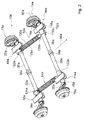
- FIG. 8 shows a perspective view of an alternative axle device with two axes 14c, 16c.
- the axes 14c, 16c have the same structure, so that the following description can be limited to the axis 16c.
- the axle 16c has a bearing unit 36c which is arranged between two axle elements 30c, 32c of the axle 16c and which pivotably connects the axle elements 30c, 32c relative to one another.
- the bearing unit 36c has a clamping unit 144c which is provided to brace the axle elements 30c, 32c and bearings 40c, 42c of the bearing unit 36c ( Fig. 9 ).
- the clamping unit 144c has a clamping element 146c, which is arranged in a coupling region 148c of the axle elements 30c, 32c.
- the clamping element 146c is formed by an inner bolt 154c of the clamping unit 144c and has a thread 152c which is arranged in the coupling region 148c of the axle elements 30c, 32c.
- the inner bolt 154c is rotatably connected to the axle member 32c.
- the inner bolt 154c is fastened to an end of the axle element 32c facing the axle element 30c.
- the inner bolt 154c is partially inserted into the shaft member 32c.
- the axle element 32c and the inner bolt 154c are non-rotatably connected via a welded connection.
- the thread 152c is arranged on an end of the inner bolt 154c facing away from the axle element 32c.
- the inner bolt 154c is stepped in the direction away from the shaft member 32c direction with a decreasing diameter.
- the bearings 40c, 42c of the bearing unit 36c are arranged on the inner bolt 154c.
- the bearings 40c, 42c are formed as double row angular contact ball bearings.
- the bearings 40c, 42c are mounted in a portion of the inner bolt 154c thereon, which has an outer diameter smaller than an outer diameter of the shaft member 32c.
- the outer diameter of the inner bolt 154c in this area is smaller than an inner diameter of the pipe-formed shaft member 32c, whereby the bearings 40c, 42c can be advantageously integrated.
- the bearings 40c, 42c of the bearing unit 36c and the axle elements 30c, 32c are clamped together.
- a nut 164c is screwed, which loads an inner ring of the bearing 40c in the direction of the shaft member 32c and applies a clamping force on this.
- the clamping force is transmitted via a spacer inner ring 166c on an inner ring of the bearing 42c, wherein the inner ring of the bearing 42c is supported on a shoulder 174c of the inner bolt 154c.
- a sleeve 168c in which the inner bolt 154c is mounted in the mounted state, is fastened to an end of the shaft element 30c facing the axle element 32c is inserted.
- the sleeve 168c and / or the inner bolt 154c could also be formed at least partially in one piece with the axle elements 30c, 32c.
- the sleeve 168c has, in a coupling region with the axle element 30c, a larger outer diameter than the axle element 30c and is pushed onto the axle element 30c.
- the sleeve 168c outer races of the bearings 40c, 42c are supported radially outwardly.
- the sleeve 168c has a screw connection, namely at the end of the sleeve 168c a disc 170c is screwed, which loads the outer rings of the bearing 42c in the direction of the shaft member 30c and applies a clamping force to it.
- the clamping force is transmitted via a spacer outer ring 172c on the outer ring of the bearing 40c, wherein the outer ring of the bearing 40c is supported on a shoulder 176c on the inner periphery of the sleeve 168c.
- the axle device further comprises connecting rods 52c, 54c, 156c, 158c, which are provided for coupling pivoting movements of the axle elements 26c, 28c, 30c, 32c to other units 160c, 162c in a sprung and damped manner.
- the units 160c, 162c are formed by cross members, which are arranged between longitudinal members 66c, 68c.
- the connecting rod units 52c, 54c, 156c, 158c comprise helical compression springs and gas dampers. In principle, however, other conceivable to those skilled in the useful springs and dampers are conceivable, such as air springs, leaf springs, oil dampers, etc.
Landscapes
- Engineering & Computer Science (AREA)
- Mechanical Engineering (AREA)
- Vehicle Body Suspensions (AREA)
- Rolling Contact Bearings (AREA)
Abstract
Die Erfindung geht aus von einer Achsvorrichtung für ein Fahrzeug (12a) insbesondere für ein Straßenfahrzeug, mit zumindest einer Achse (14a, 16a; 14b), die zumindest zwei Längslenker (18a, 20a, 22a, 24a; 18b, 20b) umfasst, die jeweils zu einer Lagerung eines Laufrads vorgesehen sind, sowie zumindest zwei Achselemente (26a, 28a, 30a, 32a; 26b, 28b), die jeweils drehfest mit einem der Längslenker (18a, 20a, 22a, 24a; 18b, 20b) verbunden sind. Es wird vorgeschlagen, dass die Achse (14a, 16a; 14b) zumindest eine Lagereinheit (34a, 36a; 34b) aufweist, die axial zwischen den Achselementen (26a, 28a, 30a, 32a; 26b, 28b) angeordnet ist.The invention relates to an axle device for a vehicle (12a), in particular for a road vehicle, having at least one axle (14a, 16a, 14b) which comprises at least two trailing arms (18a, 20a, 22a, 24a, 18b, 20b) are each provided to a storage of an impeller, and at least two axle elements (26a, 28a, 30a, 32a, 26b, 28b), each rotatably connected to one of the trailing arms (18a, 20a, 22a, 24a, 18b, 20b) are connected. It is proposed that the axle (14a, 16a, 14b) has at least one bearing unit (34a, 36a, 34b) arranged axially between the axle elements (26a, 28a, 30a, 32a, 26b, 28b).
Description
Die Erfindung betrifft eine Achsvorrichtung für ein Fahrzeug nach dem Oberbegriff des Anspruchs 1.The invention relates to an axle device for a vehicle according to the preamble of claim 1.
Es ist bereits eine Achsvorrichtung für ein Fahrzeug, mit zumindest einer Achse, die zumindest zwei Längslenker umfasst, die jeweils zu einer Lagerung eines Laufrads vorgesehen sind, sowie zumindest zwei Achselemente, die jeweils drehfest mit einem der Längslenker verbunden sind, vorgeschlagen worden.It is already an axle device for a vehicle, with at least one axle, which comprises at least two trailing arms, which are each provided to a bearing of an impeller, as well as at least two axle elements, each rotatably connected to one of the trailing arm, have been proposed.
Die Aufgabe der Erfindung besteht insbesondere darin, eine besonders kompakte Achsvorrichtung bereitzustellen. Die Aufgabe wird erfindungsgemäß durch die Merkmale des Patentanspruchs 1 gelöst, während vorteilhafte Ausgestaltungen und Weiterbildungen der Erfindung den Unteransprüchen entnommen werden können.The object of the invention is, in particular, to provide a particularly compact axle device. The object is achieved by the features of claim 1, while advantageous embodiments and modifications of the invention can be taken from the dependent claims.
Die Erfindung geht aus von einer Achsvorrichtung für ein Fahrzeug, insbesondere für ein Straßenfahrzeug, und ganz besonders bevorzugt für Kraftfahrzeuge zur Güterbeförderung, insbesondere mit einer zulässigen Gesamtmasse über 1 Tonne, und für Anhänger, einschließlich Sattelanhänger, insbesondere mit einer Gesamtmasse über 0,75 Tonnen, mit zumindest einer Achse, die zumindest zwei Längslenker umfasst, die jeweils zu einer Lagerung eines Laufrads vorgesehen sind, sowie zumindest zwei Achselemente, die jeweils drehfest mit einem der Längslenker verbunden sind.The invention relates to an axle device for a vehicle, in particular for a road vehicle, and very particularly preferably for motor vehicles for freight transport, in particular with a maximum permissible mass over 1 ton, and for trailers, including semi-trailers, in particular with a total mass over 0.75 tons , with at least one axle, which comprises at least two trailing arms, which are each provided to a bearing of an impeller, as well as at least two axle elements, which are each rotatably connected to one of the trailing arm.
Es wird vorgeschlagen, dass die Achse zumindest eine Lagereinheit aufweist, die axial zwischen den Achselementen angeordnet ist. Dadurch kann eine besonders leichte Achsvorrichtung bereitgestellt werden. Es kann ein besonders kompakter Aufbau der Achsvorrichtung erreicht werden. Es kann eine große Zahl von Gleichteilen erreicht werden, wodurch eine besonders kostengünstige Achsvorrichtung bereitgestellt werden kann. Es kann eine besonders servicefreundliche Achsvorrichtung bereitgestellt werden. Es kann eine besonders kostengünstige Montage der Achsvorrichtung erreicht werden.It is proposed that the axle has at least one bearing unit which is arranged axially between the axle elements. As a result, a particularly lightweight axle device can be provided. It can be achieved a particularly compact design of the axle device. It can be achieved a large number of identical parts, whereby a particularly inexpensive axle device can be provided. A particularly service-friendly axle device can be provided. It can be achieved a particularly cost-effective installation of the axle device.
Unter einem "Achselement" soll in diesem Zusammenhang insbesondere ein Element verstanden werden, das dazu vorgesehen ist, eine Last, insbesondere aufgrund einer Gewichtskraft auf ein Laufrad zu übertragen und/oder ein von dem Längslenker erzeugtes Drehmoment aufzunehmen. Bevorzugt ist das Achselement drehbar gelagert und weist eine Drehachse auf, die zumindest im Wesentlichen parallel zu einer Drehachse des Laufrads ausgerichtet ist. Bevorzugt weist das Achselement eine Haupterstreckungsrichtung auf, die zumindest im Wesentlichen parallel zu der Drehachse ausgerichtet ist. Vorzugsweise ist das Achselement zylindrisch ausgebildet und/oder weist zumindest einen zylindrischen Abschnitt auf. Es ist denkbar, dass das Achselement rohrförmig ausgebildet ist, und/oder zumindest einen rohrförmig ausgebildeten Abschnitt aufweist. Vorzugsweise sind die Achselemente der Achse analog zueinander ausgebildet. Dadurch kann ein besonders einfacher Aufbau der Achsvorrichtung erreicht werden. Bevorzugt weisen die Achselemente der Achse zumindest einen gleichen Außendurchmesser und/oder einen gleichen Innendurchmesser auf. Alternativ können die Achselemente unterschiedliche Außendurchmesser und/oder unterschiedliche Innendurchmesser aufweisen. Es ist denkbar, dass die Achselemente der Achse eine gleiche Länge in der Haupterstreckungsrichtung aufweisen. Alternativ können die Achselemente der Achse unterschiedliche Längen in der jeweiligen Haupterstreckungsrichtung aufweisen. Vorzugsweise sind die Achselemente in einem montierten Zustand in axialer Richtung fluchtend zueinander angeordnet. Bevorzugt sind die Achselemente in axialer Richtung beabstandet zueinander angeordnet. Es ist auch denkbar, dass die Achselemente in axialer Richtung überlappend angeordnet sind. Unter "zwischen" soll in diesem Zusammenhang insbesondere räumlich zwischen und/oder wirkungsmäßig zwischen verstanden werden. Vorzugsweise ist die zumindest eine Lagereinheit dazu vorgesehen, zumindest eines der Achselemente schwenkbar und/oder drehbar zu lagern. Bevorzugt ist die zumindest eine Lagereinheit dazu vorgesehen, die Achselemente schwenkbar und/oder drehbar gegeneinander zu lagern. Unter "axial" soll in diesem Zusammenhang insbesondere in Richtung einer Drehachse und/oder in Richtung einer zumindest im Wesentlichen parallel zu einer Seitenfläche verlaufenden Haupterstreckung verstanden werden. Unter "fluchtend" soll insbesondere verstanden werden, dass ein erstes Bauteil ausgehend von einem fiktiven Punkt und/oder einem zweiten Bauteil perspektivisch sowohl in Bezug auf eine ausgezeichnete Richtung, wie insbesondere eine Drehachse, eine Bewegungsrichtung und/oder eine Haupterstreckungsrichtung, als auch in Bezug auf eine räumliche Positionierung mit dem fiktiven Punkt und/oder dem zweiten Bauteil übereinstimmt. Unter "vorgesehen" soll insbesondere speziell ausgelegt und/oder ausgestattet verstanden werden. Darunter, dass ein Objekt zu einer bestimmten Funktion vorgesehen ist, soll insbesondere verstanden werden, dass das Objekt diese bestimmte Funktion in zumindest einem Anwendungs- und/oder Betriebszustand erfüllt und/oder ausführt.In this context, an "axle element" is to be understood as meaning, in particular, an element which is intended to transmit a load, in particular due to a weight force, to an impeller and / or to absorb a torque generated by the trailing arm. Preferably, the axle is rotatably mounted and has an axis of rotation, which is aligned at least substantially parallel to a rotational axis of the impeller. The axle element preferably has a main extension direction which is aligned at least substantially parallel to the axis of rotation. Preferably, the axle is cylindrical and / or has at least one cylindrical portion. It is conceivable that the axle element is tubular, and / or has at least one tubular section. Preferably, the axle elements of the axle are designed analogously to one another. As a result, a particularly simple construction of the axle device can be achieved. The axle elements of the axle preferably have at least one identical outer diameter and / or a same inner diameter. Alternatively, the axle elements may have different outer diameters and / or different inner diameters. It is conceivable that the axle elements of the axle have an equal length in the main extension direction. Alternatively, the axle elements of the axle may have different lengths in the respective main extension direction. Preferably, the axle elements are arranged in an assembled state in the axial direction in alignment with each other. The axle elements are preferred in the axial direction spaced apart from each other. It is also conceivable that the axle elements are arranged overlapping in the axial direction. In this context, the term "between" should be understood to mean in particular spatially between and / or in terms of effect. Preferably, the at least one bearing unit is provided for pivotally and / or rotatably supporting at least one of the axle elements. Preferably, the at least one bearing unit is provided for pivotally and / or rotatably supporting the axle elements against each other. In this context, "axial" should be understood in particular in the direction of an axis of rotation and / or in the direction of a main extension extending at least substantially parallel to a side surface. By "in-line" is to be understood in particular that a first component starting from a notional point and / or a second component perspective both in terms of an excellent direction, in particular a rotation axis, a direction of movement and / or a main extension direction, as well as in relation corresponds to a spatial positioning with the fictitious point and / or the second component. By "intended" is intended to be understood in particular specially designed and / or equipped. The fact that an object is intended for a specific function should in particular mean that the object fulfills and / or executes this specific function in at least one application and / or operating state.
In einer vorteilhaften Ausgestaltung weist die Achsvorrichtung zumindest ein Zugelement auf, das dazu vorgesehen ist, eine zumindest im Wesentlichen axial gerichtete Zugkraft zwischen den Achselementen bereitzustellen. Dadurch kann eine konstruktiv einfache und/oder robuste Achsvorrichtung bereitgestellt werden. Es kann ein besonders geringer Wartungsaufwand erreicht werden. Das Zugelement weist beispielsweise zumindest eine Stange, einen Draht, ein Band, eine Kette und/oder ein Seil auf. Es ist denkbar, dass das Zugelement ein anderes dem Fachmann als sinnvoll erscheinendes langgestrecktes Element aufweist. Vorzugsweise ist das Zugelement als ein zumindest in einem entspannten Zustand biegbares Zugelement ausgebildet. Bevorzugt ist das Zugelement als ein Seil, insbesondere als ein Drahtseil ausgebildet. Unter einer "Zugkraft zwischen" zwei Elementen soll in diesem Zusammenhang insbesondere eine Kraft verstanden werden, die darauf gerichtet ist, die Elemente aufeinander zuzubewegen und/oder aufeinanderzupressen. Vorzugsweise ist das Zugelement elastisch ausgebildet. Bevorzugt ist die Zugkraft als eine Spannkraft des Zugelements ausgebildet. Es ist denkbar, dass die Achsvorrichtung eine Einstelleinheit aufweist, die dazu vorgesehen ist, die Zugkraft, insbesondere eine Spannkraft des Zugelementes, einzustellen.In an advantageous embodiment, the axle device has at least one tension element, which is provided to provide an at least substantially axially directed tensile force between the axle elements. As a result, a structurally simple and / or robust axle device can be provided. It can be achieved a very low maintenance. The tension element has, for example, at least one rod, a wire, a band, a chain and / or a rope. It is conceivable that the tension element has another elongated element that appears appropriate to the person skilled in the art. Preferably, the tension element is as at least in a relaxed Condition bendable tension element formed. Preferably, the tension element is designed as a rope, in particular as a wire rope. In this context, a "tensile force between" two elements should be understood to mean, in particular, a force which is directed towards moving the elements toward one another and / or against each other. Preferably, the tension element is elastic. Preferably, the tensile force is designed as a clamping force of the tension element. It is conceivable that the axle device has an adjustment unit which is provided to adjust the tensile force, in particular a tensioning force of the tension element.
Ferner wird vorgeschlagen, dass die Lagereinheit zumindest ein Lager aufweist, das dazu vorgesehen ist, zumindest eines der Achselemente drehbar zu lagern und die Zugkraft des Zugelements zumindest im Wesentlichen aufzunehmen. Dadurch kann ein besonders vorteilhaft kleines Lagerspiel einer Lagerung der Achselemente erreicht werden. Unter einem "Lager" soll in diesem Zusammenhang insbesondere ein Rotationslager verstanden werden. Vorzugsweise ist das Lager als ein Wälzlager, beispielsweise ein Kugellager, ein Nadellager, ein Rollenlager oder ein Kegelrollenlager ausgebildet. Es ist denkbar, dass das Lager einen anderen dem Fachmann geeignet erscheinenden Aufbau aufweist und beispielsweise als ein Gleitlager ausgebildet ist.It is also proposed that the bearing unit has at least one bearing which is provided to rotatably support at least one of the axle elements and at least substantially to absorb the tensile force of the tension element. This allows a particularly advantageous small bearing clearance storage of the axle elements can be achieved. A "bearing" is to be understood in this context in particular a rotary bearing. Preferably, the bearing is designed as a rolling bearing, for example a ball bearing, a needle bearing, a roller bearing or a tapered roller bearing. It is conceivable that the bearing has another structure which appears suitable to a person skilled in the art and is designed, for example, as a plain bearing.
In einer weiteren Ausgestaltung der Erfindung wird vorgeschlagen, dass die Lagereinheit zumindest ein Lager aufweist, das als Schräglager ausgebildet ist, und ganz besonders vorteilhaft als Doppelreihenschräglager. Dadurch kann eine besonders zuverlässige Führung der Achselemente relativ zueinander erreicht werden und es können Kräfte vorteilhaft abgestützt werden. Es kann eine besonders einfache Einstellung eines Lagerspiels erreicht werden. Unter einem "Schräglager" soll in diesem Zusammenhang insbesondere ein Lager mit einer Drehachse verstanden werden, das dazu vorgesehen ist, eine Kraft aufzunehmen, die im Wesentlichen quer zu der Drehachse und im Wesentlichen quer zu einer Ebene senkrecht zu der Drehachse ausgerichtet ist. Unter "im Wesentlichen quer" soll hier insbesondere eine Ausrichtung einer Richtung und/oder einer Achse relativ zu einer Bezugsrichtung und/oder einer Bezugsachse verstanden werden, wobei die Ausrichtung der Richtung und/oder der Achse zumindest verschieden von einer zumindest im Wesentlichen parallelen Ausrichtung zur Bezugsrichtung und/oder zur Bezugsachse ist und insbesondere windschief oder senkrecht zur Bezugsrichtung und/oder zur Bezugsachse ist. Unter "im Wesentlichen parallel" soll hier insbesondere eine Ausrichtung einer Richtung relativ zu einer Bezugsrichtung, insbesondere in einer Ebene, verstanden werden, wobei die Richtung gegenüber der Bezugsrichtung eine Abweichung insbesondere kleiner als 8 Grad, vorteilhaft kleiner als 5 Grad und besonders vorteilhaft kleiner als 2 Grad aufweist. Vorzugsweise weist das Lager zumindest eine Lagerfläche auf, deren Normalenrichtung mit der Drehachse des Lagers zumindest im Wesentlichen überall einen spitzen Winkel einschließt. Unter einer "Lagerfläche" soll in diesem Zusammenhang insbesondere eine Roll- und/oder Gleitfläche des Lagers verstanden werden, welche zumindest in einem Betriebszustand eine Rotationsbewegung zweier zu lagernder Teile zueinander ermöglicht. Unter "zumindest im Wesentlichen überall" soll in diesem Zusammenhang insbesondere auf wenigstens 70 Prozent der Fläche, vorzugsweise auf wenigstens 85 Prozent der Fläche und bevorzugt auf wenigstens 98 Prozent der Fläche verstanden werden.In a further embodiment of the invention, it is proposed that the bearing unit has at least one bearing which is designed as an angular bearing, and very particularly advantageous as a double row inclined bearing. As a result, a particularly reliable guidance of the axle elements relative to each other can be achieved and forces can be advantageously supported. It can be achieved a particularly simple setting of a bearing clearance. In this context, an "angular contact bearing" is to be understood as meaning, in particular, a bearing having an axis of rotation which is intended to receive a force which is aligned essentially transversely to the axis of rotation and substantially transverse to a plane perpendicular to the axis of rotation. By "substantially transversely" is meant in particular an orientation of a direction and / or an axis be understood relative to a reference direction and / or a reference axis, wherein the orientation of the direction and / or the axis is at least different from an at least substantially parallel orientation to the reference direction and / or the reference axis and in particular skewed or perpendicular to the reference direction and / or Reference axis is. "Substantially parallel" is to be understood here as meaning, in particular, an orientation of a direction relative to a reference direction, in particular in a plane, wherein the direction relative to the reference direction is a deviation, in particular less than 8 degrees, advantageously less than 5 degrees and particularly advantageously less than 2 degrees. The bearing preferably has at least one bearing surface whose normal direction encloses an acute angle with the axis of rotation of the bearing at least substantially everywhere. In this context, a "bearing surface" is to be understood as meaning, in particular, a rolling and / or sliding surface of the bearing, which enables a rotational movement of two parts to be supported relative to one another, at least in one operating state. By "at least substantially everywhere" in this context is meant in particular at least 70 percent of the area, preferably at least 85 percent of the area and preferably at least 98 percent of the area.
Ferner wird vorgeschlagen, dass die Lagereinheit eine Spanneinheit aufweist, die dazu vorgesehen ist, die Achselemente und/oder Lager der Lagereinheit zu verspannen, wodurch eine besonders robuste und stabile Konstruktion erreicht werden kann. Unter einer "Spanneinheit" soll dabei insbesondere eine Einheit verstanden werden, mittels deren eine Spannkraft erzeugt werden kann, und zwar insbesondere in der Art, dass zumindest zwei Bauteile miteinander mit einer Spannkraft verspannt werden können.It is further proposed that the bearing unit has a clamping unit which is provided to brace the axle elements and / or bearings of the bearing unit, whereby a particularly robust and stable construction can be achieved. A "clamping unit" should be understood to mean in particular a unit by means of which a clamping force can be generated, in particular in such a way that at least two components can be clamped together with a clamping force.
Weist die Spanneinheit wenigstens ein Spannelement auf, das in einem Koppelbereich der Achselemente angeordnet ist, kann die Spanneinheit besonders Platz sparend, insbesondere Platz sparend zumindest teilweise innerhalb zumindest eines Achselements, integriert werden. Dabei soll unter "in einem Koppelbereich der Achselemente angeordnet" insbesondere verstanden werden, dass das Spannelement zumindest einen kürzesten Abstand, insbesondere parallel zu den Achselementen, von einer Ebene aufweist, die senkrecht zur Längsrichtung der Achselemente verläuft und in der zumindest ein dem Koppelbereich zugewandtes freies Ende eines der Achselemente liegt, wobei der Abstand kleiner ist als ein kürzester Abstand, insbesondere parallel zu den Achselementen, von einer Ebene, die senkrecht zur Längsrichtung der Achselemente verläuft und in der zumindest ein dem Koppelbereich abgewandtes freies Ende eines der Achselemente liegt. Besonders vorteilhaft weist das Spannelement einen kürzesten Abstand von einem dem Koppelbereich zugewandten freien Ende eines der Achselemente auf, der kleiner ist als 50% einer Gesamtlänge des Achselements und insbesondere kleiner ist als 30% der Gesamtlänge des Achselements. Ferner soll unter einem "Koppelbereich der Achselemente" insbesondere ein Bereich verstanden werden, in dem in Längsrichtung betrachtet beide den Längslenkern abgewandten Enden der Achselemente angeordnet sind und der einen Abstand zu den den Längslenkern zugewandten Enden der Achselemente aufweist, und zwar insbesondere von zumindest 10% einer Gesamtlänge eines der Achselemente und vorteilhaft von zumindest 20% einer Gesamtlänge eines der Achselemente. Ferner soll unter einem "Spannelement" insbesondere ein Element verstanden werden, das dazu vorgesehen ist, eine Spannkraft zu erzeugen, wie beispielsweise mittels eines Hebelmechanismus, mittels eines Kurvengetriebes und/oder mittels eines Gewindes usw.If the clamping unit has at least one clamping element which is arranged in a coupling region of the axle elements, the clamping unit can be integrated in a particularly space-saving manner, in particular to save space at least partially within at least one axle element. It should under "in a coupling region of the axle elements arranged "in particular be understood that the clamping element has at least a shortest distance, in particular parallel to the axle elements, of a plane which is perpendicular to the longitudinal direction of the axle and in which at least one of the coupling region facing free end of the axle elements , wherein the distance is smaller than a shortest distance, in particular parallel to the axle elements, from a plane which is perpendicular to the longitudinal direction of the axle elements and in which at least one free end of one of the axle elements faces away from the coupling region Distance from a free end of one of the axle elements facing the coupling region, which is smaller than 50% of a total length of the axle element and in particular smaller than 30% of the total length of the axle element be understood in the longitudinal direction both the trailing arms facing away from the axle elements are arranged and which has a distance from the trailing arms facing ends of the axle elements, in particular of at least 10% of an overall length of the axle elements and advantageously of at least 20% a total length of one of the axle elements. Furthermore, a "tensioning element" should be understood to mean, in particular, an element which is intended to generate a tensioning force, for example by means of a lever mechanism, by means of a cam mechanism and / or by means of a thread, etc.
Ferner wird vorgeschlagen, dass das wenigstens eine Spannelement zumindest ein Gewinde aufweist, wodurch konstruktiv einfach Spannkräfte erzeugt werden können. Das Gewinde kann dabei als ein Innengewinde und/oder vorteilhaft als ein Außengewinde ausgebildet sein.It is also proposed that the at least one clamping element has at least one thread, whereby structurally simple clamping forces can be generated. The thread may be formed as an internal thread and / or advantageously as an external thread.
In einer weiteren Ausgestaltung wird vorgeschlagen, dass die Spanneinheit einen Innenbolzen aufweist, wodurch wiederum eine vorteilhaft Platz sparende Integration erreicht werden kann. Dabei soll unter einem "Innenbolzen insbesondere ein Element verstanden werden, das dazu vorgesehen ist, bei der Montage zumindest teilweise in einen Hohlraum eines Elements, wie insbesondere in einen Hohlraum eines Achselements, eingeführt zu werden.In a further embodiment, it is proposed that the clamping unit has an inner bolt, which in turn can be advantageously achieved space-saving integration. It should under an "internal bolt In particular, an element can be understood, which is intended to be at least partially introduced during assembly in a cavity of an element, in particular in a cavity of a shaft element.
Der Innenbolzen ist vorzugsweise mit einem der Achselemente drehfest verbunden, wodurch einfach vorteilhafte Kraftverläufe sichergestellt werden können.The inner bolt is preferably non-rotatably connected to one of the axle elements, whereby simply advantageous force courses can be ensured.
Ferner ist zumindest ein Lager der Lagereinheit zumindest teilweise auf dem Innenbolzen angeordnet, wodurch die Lagereinheit und insbesondere zumindest eines von deren Lagern konstruktiv einfach innerhalb der Achselemente angeordnet werden kann.Furthermore, at least one bearing of the bearing unit is at least partially disposed on the inner bolt, whereby the bearing unit and in particular at least one of their bearings can be arranged structurally simple within the axle elements.
In einer weiteren Ausgestaltung der Erfindung wird vorgeschlagen, dass der Innenbolzen ein im Koppelbereich der Achselemente angeordnetes Gewinde aufweist, über das zumindest ein Lager der Lagereinheit und/oder die Achselemente verspannbar sind, wodurch eine einfache und kostengünstige Konstruktion erreicht werden kann. Der Innenbolzen bildet vorzugsweise zumindest teilweise das Spannelement der Spanneinheit, das im Koppelbereich der Achselemente angeordnet ist.In a further embodiment of the invention, it is proposed that the inner bolt has a thread arranged in the coupling region of the axle elements, via which at least one bearing of the bearing unit and / or the axle elements can be braced, whereby a simple and inexpensive construction can be achieved. The inner bolt preferably forms at least partially the clamping element of the clamping unit, which is arranged in the coupling region of the axle elements.
In einer vorteilhaften Ausgestaltung durchsetzt das Zugelement zumindest eines der Achselemente in axialer Richtung. Dadurch kann das Zugelement besonders zuverlässig vor Umwelteinflüssen geschützt werden. Es kann ein geringer Bauraumbedarf erreicht werden. Unter "axial durchsetzen" soll in diesem Zusammenhang insbesondere verstanden werden, dass ein Element zumindest an einem Querschnitt, der senkrecht zu der axialen Richtung angeordnet ist, vorzugsweise in einem axialen Bereich, radial zumindest im Wesentlichen vollständig innerhalb eines weiteren Elements angeordnet ist. Vorzugsweise durchsetzt das Zugelement zumindest eines der Achselemente zumindest auf einer Länge, die 50 Prozent einer Haupterstreckung des Achselements entspricht, bevorzugt auf einer Länge die 80 Prozent einer Haupterstreckung des Achselements entspricht, besonders bevorzugt auf einer Länge die 90 Prozent einer Haupterstreckung des Achselements entspricht, und ganz besonders bevorzugt auf einer Länge, die 99 Prozent einer Haupterstreckung des Achselements entspricht. Vorzugsweise durchsetzt das Zugelement beide Achselemente.In an advantageous embodiment, the tension element passes through at least one of the axle elements in the axial direction. As a result, the tension element can be protected particularly reliably against environmental influences. It can be achieved a small space requirement. By "axially pass through" is to be understood in this context in particular that an element is arranged at least at a cross section which is perpendicular to the axial direction, preferably in an axial region, radially at least substantially completely within a further element. Preferably, the tension element penetrates at least one of the axle elements at least over a length which corresponds to 50 percent of a main extension of the axle element, preferably on a length corresponding to 80 percent of a major extension of the shaft member, more preferably to a length corresponding to 90 percent of a major extension of the shaft member, and most preferably to a length corresponding to 99 percent of a major extension of the shaft member. Preferably, the tension element passes through both axle elements.
Ferner wird vorgeschlagen, dass die Achsvorrichtung zumindest eine Lagerstelle zu einer direkten Lagerung eines ersten der Achselemente und zumindest eine weitere Lagerstelle zu einer direkten Lagerung eines weiteren der Achselemente. Dadurch kann eine zuverlässige Lagerung der Achselemente erreicht werden. Es kann ein besonders hoher Fahrkomfort erreicht werden. Unter einer "direkten Lagerung" soll in diesem Zusammenhang insbesondere verstanden werden, dass in einem montierten Zustand ein zu lagerndes Element und ein Lager miteinander in Kontakt sind. Vorzugsweise weist die Lagerstelle eine axiale Erstreckung von weniger als 180 mm, bevorzugt von weniger als 120 mm und besonders bevorzugt von weniger als 90 mm auf.It is also proposed that the axle device has at least one bearing point for a direct bearing of a first of the axle elements and at least one further bearing point for a direct bearing of a further one of the axle elements. As a result, a reliable storage of the axle elements can be achieved. It can be achieved a particularly high ride comfort. In this context, "direct storage" is to be understood in particular as meaning that in an assembled state, an element to be stored and a bearing are in contact with one another. Preferably, the bearing has an axial extent of less than 180 mm, preferably less than 120 mm, and more preferably less than 90 mm.
In einer vorteilhaften Weise sind die Lagerstelle und die zumindest eine weitere Lagerstelle dazu vorgesehen, die Achselemente unabhängig voneinander zu lagern. Dadurch sind die Achselemente gegeneinander verdrehbar. Es kann ein besonders guter Kontakt zwischen einer Fahrbahn und dem Fahrzeug erreicht werden. Es kann ein besonders sicher betreibbares Fahrzeug bereitgestellt werden. Laufräder können nach dem Prinzip einer Einzelradaufhängung gelagert werden. Es kann ein hoher Fahrkomfort erreicht werden. Unter "unabhängig voneinander lagern" soll in diesem Zusammenhang insbesondere verstanden werden, dass eine Drehbewegung an den Lagerstellen zumindest im Wesentlichen voneinander entkoppelt sind. Insbesondere weisen die Lagerstellen jeweils Lager auf, die zumindest im Wesentlichen drehmomentübertragungsfrei voneinander ausgebildet sind.In an advantageous manner, the bearing point and the at least one further bearing point are provided to store the axle elements independently of each other. As a result, the axle elements are rotated against each other. It can be achieved a particularly good contact between a road and the vehicle. It can be provided a particularly safe operable vehicle. Impellers can be stored on the principle of independent suspension. It can be achieved a high ride comfort. By "store independently of one another" is to be understood in this context, in particular, that a rotational movement at the bearing points are at least substantially decoupled from each other. In particular, the bearings each have bearings that are formed at least substantially free of torque transmission from each other.
Ferner wird eine Achsvorrichtung, insbesondere für ein Straßenfahrzeug, vorgeschlagen mit zumindest zwei Achsen, die jeweils zumindest zwei Längslenker umfassen, die jeweils zu einer Lagerung eines Laufrads vorgesehen sind, sowie zumindest zwei Achselemente, die jeweils drehfest mit einem der Längslenker verbunden sind, wobei die Achsen jeweils eine Lagereinheit aufweisen, die jeweils axial zwischen den Achselementen der jeweiligen Achse angeordnet ist. Dadurch kann eine Achsvorrichtung für besonders große Lasten bereitgestellt werden. Es kann eine besonders vielseitig einsetzbare Achsvorrichtung bereitgestellt werden.Further, an axle device, in particular for a road vehicle, proposed with at least two axles, each comprising at least two trailing arms, which are each provided to a bearing of an impeller, and at least two axle elements, each rotatably connected to one of the trailing arm, wherein the Axles each have a bearing unit, which is arranged in each case axially between the axle elements of the respective axis. As a result, an axle device for particularly large loads can be provided. It can be provided a particularly versatile axle device.
Ferner wird vorgeschlagen, dass die Achsvorrichtung zumindest eine Pleueleinheit aufweist, die dazu vorgesehen ist, eine Schwenkbewegung zumindest eines der Achselemente gefedert und/oder gedämpft mit zumindest einer weiteren Einheit zu koppeln, wodurch eine vorteilhaft stabile Lagerung der Längslenker und damit der Laufräder erreicht werden kann. Insbesondere ist die Pleueleinheit dabei dazu vorgesehen, die Schwenkbewegungen gedämpft abzufedern. Dabei können verschiedene, dem Fachmann als sinnvoll erscheinende Dämpfer und/oder Federelemente eingesetzt werden, wie beispielsweise Gasdämpfer, Öldämpfer, Schraubenfedern, Blattfedern usw.It is also proposed that the axle device has at least one connecting rod unit which is provided to couple a pivoting movement of at least one of the axle elements sprung and / or damped with at least one further unit, whereby an advantageously stable mounting of the trailing arm and thus the wheels can be achieved , In particular, the connecting rod unit is intended to dampen the pivoting movements attenuated. It can be used various, the skilled worker appear appropriate damper and / or spring elements, such as gas damper, oil damper, coil springs, leaf springs, etc.
In einer vorteilhaften Ausgestaltung weist die Achsvorrichtung zumindest eine elastisch verformbares Pleueleinheit auf, die dazu vorgesehen ist, eine Schwenkbewegung eines der Achselemente einer ersten der Achsen mit einer Schwenkbewegung eines der Achselemente einer weiteren Achse zu koppeln. Dadurch können Stöße, die bei einer Fahrt auf die Längslenker einwirken, besonders wirkungsvoll gedämpft werden. Es kann eine anwenderspezifische Federeinstellung ermöglicht werden. Eine Ruhelage der Achselemente kann besonders einfach eingestellt werden. Unter einem "verformbaren Pleuelelement" soll in diesem Zusammenhang insbesondere ein Pleuelelement verstanden werden, das, insbesondere bezogen auf eine Haupterstreckungsrichtung, verkürzbar und/oder verlängerbar ist.In an advantageous embodiment, the axle device has at least one elastically deformable connecting rod unit, which is provided to couple a pivoting movement of one of the axle elements of a first of the axles with a pivoting movement of one of the axle elements of a further axle. As a result, shocks that act on the trailing arm during a ride, are particularly effectively damped. A user-specific spring adjustment can be made possible. A rest position of the axle elements can be adjusted very easily. In this context, a "deformable connecting rod element" is to be understood as meaning, in particular, a connecting rod element be, which, in particular with respect to a main extension direction, shortened and / or extendable.
Ferner wird vorgeschlagen, dass die zumindest eine Pleueleinheit zumindest ein Rückstellelement aufweist, das dazu vorgesehen ist, einer Verformung der Pleueleinheit entgegenzuwirken. Dadurch kann ein Abheben der Laufräder von einer Fahrbahn besonders wirkungsvoll verhindert werden. Eine Sicherheit beim Betrieb des Fahrzeugs kann weiter erhöht werden. Unter einer "Verformung" soll in diesem Zusammenhang insbesondere eine Längenänderung, insbesondere bezogen auf eine Haupterstreckungsrichtung, verstanden werden. Vorzugsweise ist das Rückstellelement als eine Schraubenfeder ausgebildet. Es ist denkbar, dass das Rückstellelement als ein anderes dem Fachmann geeignet erscheinendes elastisches Element ausgebildet ist, beispielsweise als ein Kunststoffelement oder eine Gasfeder.It is also proposed that the at least one connecting rod unit has at least one return element which is intended to counteract a deformation of the connecting rod unit. As a result, lifting of the wheels from a roadway can be prevented particularly effectively. Safety during operation of the vehicle can be further increased. In this context, a "deformation" is to be understood as meaning in particular a change in length, in particular with respect to a main extension direction. Preferably, the return element is designed as a helical spring. It is conceivable that the restoring element is designed as another elastic element which appears suitable to the person skilled in the art, for example as a plastic element or a gas spring.
Ferner wird ein Fahrzeug, insbesondere ein Straßenfahrzeug, mit zumindest einer erfindungsgemäßen Achsvorrichtung vorgeschlagen. Dadurch kann ein Fahrzeug mit einem besonders hohen Benutzerkomfort bereitgestellt werden. Es kann ein Fahrzeug mit einem besonders großen Nutzlastvolumen und/oder einer besonders großen Nutzlastmasse bereitgestellt werden.Furthermore, a vehicle, in particular a road vehicle, with at least one axle device according to the invention is proposed. Thereby, a vehicle with a particularly high user comfort can be provided. A vehicle with a particularly large payload volume and / or a particularly large payload mass can be provided.
Die erfindungsgemäße Achsvorrichtung soll hierbei nicht auf die oben beschriebene Anwendung und Ausführungsform beschränkt sein. Insbesondere kann die erfindungsgemäße Achsvorrichtung zu einer Erfüllung einer hierin beschriebenen Funktionsweise eine von einer hierin genannten Anzahl von einzelnen Elementen, Bauteilen und Einheiten abweichende Anzahl aufweisen.The axle device according to the invention should not be limited to the application and embodiment described above. In particular, to fulfill a mode of operation described herein, the axle device according to the invention may have a number deviating from a number of individual elements, components and units mentioned herein.
Weitere Vorteile ergeben sich aus der folgenden Zeichnungsbeschreibung. In den Zeichnungen sind zwei Ausführungsbeispiele der Erfindung dargestellt. Die Zeichnungen, die Beschreibung und die Ansprüche enthalten zahlreiche Merkmale in Kombination. Der Fachmann wird die Merkmale zweckmäßigerweise auch einzeln betrachten und zu sinnvollen weiteren Kombinationen zusammenfassen.Further advantages emerge from the following description of the drawing. In the drawings, two embodiments of the invention are shown. The drawings, the description and the claims contain numerous features in combination. The person skilled in the art will expediently also consider the features individually and combine them into meaningful further combinations.
Es zeigen:
- Fig. 1
- eine perspektivische Ansicht eines Fahrzeugs mit einer erfindungsgemäßen Achsvorrichtung,
- Fig. 2
- eine perspektivische Ansicht der Achsvorrichtung,
- Fig. 3
- eine Aufsicht auf die Achsvorrichtung,
- Fig. 4
- eine teilgeschnittene Ansicht einer ersten Achse der Achsvorrichtung entlang einer Drehachse der Achse,
- Fig. 5
- eine Schnittansicht einer Lagereinheit der Achse,
- Fig. 6
- eine Schnittansicht der Lagereinheit entlang einer Ebene senkrecht zu der Drehachse der Achse,
- Fig. 7
- eine perspektivische Ansicht einer Achse eines weiteren Ausführungsbeispiels,
- Fig. 8
- eine perspektivische Ansicht einer alternativen Achsvorrichtung und
- Fig. 9
- einen Längsschnitt durch einen Koppelbereich von Achselementen der Achsvorrichtung aus
Fig. 8 .
- Fig. 1
- a perspective view of a vehicle with an axle device according to the invention,
- Fig. 2
- a perspective view of the axle device,
- Fig. 3
- a view of the axle device,
- Fig. 4
- a partially sectioned view of a first axis of the axle along an axis of rotation of the axis,
- Fig. 5
- a sectional view of a bearing unit of the axis,
- Fig. 6
- a sectional view of the bearing unit along a plane perpendicular to the axis of rotation of the axis,
- Fig. 7
- a perspective view of an axis of another embodiment,
- Fig. 8
- a perspective view of an alternative axle and
- Fig. 9
- a longitudinal section through a coupling region of axle elements of the axle device
Fig. 8 ,
Eine erste der Achsen 14a und eine weitere der Achsen 16a sind in Hinsicht auf die im Folgenden beschriebenen Merkmale analog zueinander ausgebildet, weshalb nur die erste der Achsen 14a näher beschrieben wird. Die Achse 14a ist in dem vorliegenden Ausführungsbeispiel als nicht-lenkbare Achse 14a ausgebildet. Die Achse 14a ist zu einer Lagerung von zwei Laufrädern 70a, 72a vorgesehen, die an einander abgewandten Seiten des Fahrzeugs 12a angeordnet sind. Die Laufräder 70a, 72a sind in einem montierten Zustand an einander abgewandten Seiten der Achse 14a angeordnet. Die Achse 14a ist räumlich zwischen einer Fahrbahnebene und den Längsträgern 66a, 68a des Fahrzeugs 12a angeordnet. Die Achse 14a weist eine Drehachse 78a auf, die zumindest im Wesentlichen senkrecht zu der Hauptfahrtrichtung 56a ausgerichtet ist. Die Achse 14a ist dazu vorgesehen, insbesondere ein Gewicht der Nutzlast und/oder des Fahrzeugs 12a von den Längsträgern 66a, 68a auf die an der Achse 14a gelagerten Laufräder 70a, 72a zu übertragen. Die Laufräder 70a, 72a sind dazu vorgesehen, insbesondere ein Gewicht der Nutzlast und/oder des Fahrzeugs 12a auf eine Fahrbahn zu übertragen.A first one of the
Die erste Achse 14a weist zwei Längslenker 18a, 20a auf, die jeweils zu einer Lagerung eines der Laufräder 70a, 72a des Fahrzeugs 12a vorgesehen sind (vgl.
Die Längslenker 18a, 20a sind analog zueinander ausgebildet, weshalb im Folgenden nur der erste der Längslenker 18a näher beschrieben wird. Der erste Längslenker 18a ist langgestreckt ausgebildet und weist bezogen auf eine Haupterstreckungsrichtung zwei voneinander abgewandte Enden auf. Der Längslenker 18a ist an einem ersten der Enden schwenkbar bezogen auf die Drehachse 78a der Achse 14a gelagert. Der Längslenker 18a weist einen Drehpunkt auf, der auf der Drehachse 78a der Achse 14a angeordnet ist. Das an dem Längslenker 18a gelagerte Laufrad 70a weist eine Drehachse 80a auf. Die Drehachse 80a des Laufrads 70a ist an einem weiteren der Enden des Längslenkers 18a angeordnet. Die Drehachse 80a des Laufrads 70a und der Drehpunkt des Längslenkers 18a sind beabstandet voneinander angeordnet. Der Längslenker 18a ist dazu vorgesehen, zu einer Änderung eines Abstands zwischen dem an dem Längslenker 18a gelagerten Laufrad 70a und den Längsträgern 66a, 68a geschwenkt zu werden.The trailing
Die Achse 14a umfasst zwei Achselemente 26a, 28a, die jeweils drehfest mit einem der Längslenker 18a, 20a verbunden sind. Analog umfasst die weitere Achse 16a zwei Achselemente 30a, 32a. Je eines der Achselemente 26a, 28a ist jeweils einem der Längslenker 18a, 20a zugeordnet. Die Achselemente 26a, 28a der ersten Achse 14a weisen eine Haupterstreckung in Richtung der Drehachse 80a der Achse 14a auf. Die Achselemente 26a, 28a sind fluchtend zueinander angeordnet. Die Achselemente 26a, 28a sind kolinear zueinander angeordnet. Die Achselemente 26a, 28a sind zu einer Drehung um die Drehachse 78a der Achse 14a vorgesehen. Die Achselemente 26a, 28a weisen in dem vorliegenden Ausführungsbeispiel eine gleiche axiale Erstreckung auf. Es ist denkbar, dass die Achselemente 26a, 28a eine unterschiedliche axiale Erstreckung aufweisen. Ein erstes der Achselemente 26a ist bezogen auf die Hauptfahrtrichtung 56a des Fahrzeugs 12a links von der Achsmitte angeordnet. Ein weiteres der Achselemente 28a ist bezogen auf die Hauptfahrtrichtung 56a des Fahrzeugs 12a rechts von der Achsmitte angeordnet. In dem vorliegenden Ausführungsbeispiel sind die Achselemente 26a, 28a analog zueinander ausgebildet, weshalb im Folgenden nur das erste der Achselemente 26a näher beschrieben wird.The
Das Achselement 26a ist in dem vorliegenden Ausführungsbeispiel formschlüssig mit dem ihm zugeordneten Längslenker 18a verbunden. Das Achselement 26a und der Längslenker 18a sind mittels eines Bolzens miteinander verbunden. Das Achselement 26a und der Längslenker 18a sind miteinander verschraubt. Es ist denkbar, dass das Achselement 26a und der Längslenker 18a auf eine andere dem Fachmann geeignet erscheinende Weise, beispielsweise stoffschlüssig miteinander verbunden sind. Das Achselement 26a weist zwei in axialer Richtung einander gegenüberliegend angeordnete Enden auf. Das Achselement 26a weist ein bezogen auf eine Achsmitte äußeres Ende und ein bezogen auf eine Achsmitte inneres Ende auf. Das Achselement 26a ist an dem äußeren Ende mit dem Längslenker 18a verbunden. Das Achselement 26a ist röhrenförmig ausgebildet. Das Achselement 26a ist in Form eines langgestreckten Hohlzylinders ausgebildet. Das Achselement 26a ist als ein Achsrohr ausgebildet.In the present exemplary embodiment, the
Die erste Achse 14a weist eine Lagereinheit 34a auf, die axial zwischen den Achselementen 26a, 28a angeordnet ist. Analog weist die weitere Achse 16a der Achsvorrichtung 10a eine Lagereinheit 36a auf, die axial zwischen den Achselementen 30a, 32a der weiteren Achse 16a angeordnet ist. Die Lagereinheit 34a der ersten Achse 14a ist zentral an der Achse 14a angeordnet. Die Lagereinheit 34a ist bezogen auf eine axiale Erstreckung der Achse 14a in der Achsmitte angeordnet. Es ist denkbar, dass die Lagereinheit 34a bezogen auf die axiale Erstreckung der Achse 14a außermittig angeordnet ist. Es ist denkbar, dass die Lagereinheit 34a bezogen auf die axiale Erstreckung axial beabstandet von der Achsmitte angeordnet ist. Die Lagereinheit 34a ist zwischen den Achselementen 26a, 28a der ersten Achse 14a angeordnet. Die Lagereinheit 34a ist räumlich zwischen den Achselementen 26a, 28a angeordnet. Die Lagereinheit 34a ist wirkungstechnisch zwischen den Achselementen 26a, 28a angeordnet. Die Lagereinheit 34a weist ein Stütz- und Führungselement 82a auf. Das Stütz- und Führungselement 82a ist in axialer Richtung zentral in der Lagereinheit 34a angeordnet. Das Stütz- und Führungselement 82a ist in radialer Richtung zentral in der Lagereinheit 34a angeordnet. Das Stütz- und Führungselement 82a ist in Form eines dickwandigen Hohlzylinders ausgebildet. Das Stütz- und Führungselement 82a ist koaxial zu der Achse 14a und zu den Achselementen 26a, 28a angeordnet. Die Lagereinheit 34a ist dazu vorgesehen, jedes der Achselemente 26a, 28a in axialer Richtung drehbar zu lagern. Die Lagereinheit 34a ist dazu vorgesehen, die Achselemente 26a, 28a in axialer Richtung drehbar gegeneinander zu lagern.The
Die Achsvorrichtung 10a weist ein Zugelement 38a auf, das dazu vorgesehen ist, eine zumindest im Wesentlichen axial gerichtete Zugkraft zwischen den Achselementen 26a, 28a bereitzustellen (vgl.
Die Lagereinheit 34a weist in dem vorliegenden Ausführungsbeispiel zwei Lagerteileinheiten 84a, 86a auf (vgl.
Die Lagerteileinheiten 84a, 86a sind analog zueinander ausgebildet, weshalb im Folgenden nur eine erste der Lagerteileinheiten 84a näher beschreiben wird. Die erste Lagerteileinheit 84a umfasst eines der Lager 40a der Lagereinheit 34a. Das Lager 40a ist dazu vorgesehen, das der Lagerteileinheit 84a zugeordnete Achselement 26a drehbar zu lagern. Das Lager 40a ist in dem vorliegenden Ausführungsbeispiel dazu vorgesehen, die Achselemente 26a, 28a drehbar gegeneinander zu lagern. Die Lagerteileinheit 84a umfasst ein Hülsenelement 88a. Das Hülsenelement 88a ist mit dem Achselement 26a, das der Lagerteileinheit 84a zugeordnet ist, zumindest in einer axialen Richtung zumindest kraftschlüssig verbunden. Das Hülsenelement 88a ist mit dem Achselement 26a, das der Lagerteileinheit 84a zugeordnet ist, zumindest in einer axialen Richtung formschlüssig verbunden. Das Hülsenelement 88a und das Achselement 26a weisen jeweils in radialer Richtung einander zugewandte Kontaktflächen auf. Das Hülsenelement 88a weist in axialer Richtung aufeinander folgend einen Anschlussabschnitt 90a und einen Lagerabschnitt 92a auf. Das Hülsenelement 88a ist in dem vorliegenden Ausführungsbeispiel auf das Achselement 26a aufgesteckt. Der Anschlussabschnitt 90a des Hülsenelements 88a überdeckt in einem Verbindungsbereich das Achselement 26a. Das Achselement 26a greift in dem Verbindungsbereich in das Hülsenelement 88a ein. Die Lagerteileinheit 84a weist einen senkrecht zu der Drehachse 78a des Achselements 26a angeordneten Querschnitt auf, in dem das Hülsenelement 88a das Achselement 26a umgibt. Das Achselement 26a weist eine Wandung 94a auf. An einem dem Hülsenelement 88a zugewandten Ende des Achselements 26a weist ein Längsschnitt der Wandung 94a zwei radial einander gegenüberliegende Stufen zu einer Aufnahme des Hülsenelements 88a auf. Das Hülsenelement 88a weist in dem Verbindungsbereich eine ringförmige Ausnehmung zur Aufnahme des Achselements 26a auf. Es ist auch denkbar, dass in einer alternativen Ausgestaltung das Hülsenelement 88a in das Achselement 26a eingreift. Es ist auch denkbar, dass das Hülsenelement 88a und das Achselement 26a auf andere dem Fachmann zweckmäßig erscheinende Weise, beispielsweise stoffschlüssig miteinander verbunden sind.The bearing
Der Lagerabschnitt 92a des Hülsenelements 88a ist in Form eines Hohlzylinders ausgebildet. Der Anschlussabschnitt 90a des Hülsenelements 88a ist in Form eines Hohlzylinders ausgebildet. Der Lagerabschnitt 92a weist einen größeren Durchmesser auf als der Anschlussabschnitt 90a. In dem vorliegenden Ausführungsbeispiel weist der Lagerabschnitt 92a des Hülsenelements 88a einen größeren Durchmesser auf als der Anschlussabschnitt 90a. Das Hülsenelement 88a weist eine Wandung auf. Ein Längsschnitt der Wandung weist an einem Übergang zwischen dem Lagerabschnitt 92a und dem Anschlussabschnitt 90a zwei radial einander gegenüberliegende Stufen auf.The bearing
Das Lager 40a ist als ein Schräglager ausgebildet. Das Lager 40a weist einen Außenring 96a auf. Der Außenring 96a des Lagers 40a ist zumindest in axialer Richtung fest mit dem Hülsenelement 88a verbunden. Der Außenring 96a des Lagers 40a weist eine konische Lauffläche auf. Der Außenring 96a des Lagers 40a weist einen Innenkonus auf. Der Innenkonus des Außenrings 96a ist zu einer von dem Achselement 26a abgewandten Seite hin geöffnet. Der Innenkonus verjüngt sich an einer dem Achselement 26a zugewandten Seite. Das Lager 40a weist einen Innenring 98a auf. Der Innenring 98a des Lagers 40a ist zumindest in axialer Richtung fest mit dem Stütz- und Führungselement 82a der Lagereinheit 34a verbunden. Der Innenring 98a weist eine konische Lauffläche auf. Der Innenring 98a weist einen Außenkonus auf. Der Außenkonus ist zu einer von dem Achselement 26a abgewandten Seite hin geöffnet. Der Außenkonus verjüngt sich an einer dem Achselement 26a zugewandten Seite.The
Der Innenkonus des Außenrings 96a weist in dem vorliegenden Ausführungsbeispiel einen größeren Öffnungswinkel auf als der Außenkonus des Innenrings 98a. Das Lager 40a weist eine Mehrzahl von Wälzkörpern 100a, 102a auf. In dem vorliegenden Ausführungsbeispiel sind die Wälzkörper 100a, 102a in Form von Kegelstümpfen ausgebildet. Das Lager 40a ist als ein Kegelrollenlager ausgebildet (vgl.
Ausführungsbeispiel in einer dem Achselement 26a abgewandten Richtung geöffnet ist. Der Innenring 98a des Lagers 40a ist drehfest mit dem Stütz- und Führungselement 82a verbunden. Der Innenring 98a des Lagers 40a ist drehfest mit einem Innenring 98a des Lagers 40a einer weiteren Lagerteileinheit 86a der Lagereinheit 34a verbunden.Embodiment is open in a direction away from the
In einer alternativen Ausgestaltung kann der Innenring 98a des Lagers 40a mit dem Achselement 26a drehfest verbunden und der Außenring 96a des Lagers 40a mit einem Stütz- und Führungselement 82a drehfest verbunden sein. In einer solchen Ausgestaltung können die Wälzkörper 100a, 102a jeweils eine Drehachse aufweisen, die mit der Achse 14a einen Winkel einschließt, der in einer dem Achselement 26a zugewandten Richtung geöffnet ist. In einer weiteren alternativen Ausgestaltung kann die Lagerteileinheit 86a zwei Lager aufweisen, von denen beispielsweise eines als ein Axiallager und ein weiteres als ein Radiallager ausgebildet ist. Es ist denkbar, dass die Lagereinheit 34a in einer weiteren alternativen Ausgestaltung ein einziges Lager aufweist, das die Achselemente 26a, 28a gegeneinander lagert.In an alternative embodiment, the
Das Zugelement 38a durchsetzt das erste Achselement 26a in axialer Richtung. Das Zugelement 38a durchsetzt das weitere Achselement 26a in axialer Richtung. Das Zugelement 38a durchsetzt die beiden Achselemente 26a, 28a in axialer Richtung. Das Zugelement 38a durchsetzt die Lagereinheit 34a in axialer Richtung. Das Zugelement 38a durchsetzt das Stütz- und Führungselement 82a. Das Stütz- und Führungselement 82a weist eine zentrale Bohrung in axialer Richtung auf. Die Bohrung ist zu einer Aufnahme des Zugelements 38a vorgesehen. Das Stütz- und Führungselement 82a ist dazu vorgesehen, das Zugelement 38a zu stützen und/oder zu führen. Eine Erstreckung des Zugelements 38a in Richtung der Achse 14a entspricht einer Summe aus einer Erstreckung des ersten Achselements 26a in Richtung der Achse 14a, aus einer Erstreckung des weiteren Achselements 28a in Richtung der Achse 14a und aus einer Erstreckung der Lagereinheit 34a in Richtung der Achse 14a. Die Achse 14a weist zwei Fixierelemente 104a, 106a auf, die zu einer axialen Fixierung des Zugelements 38a vorgesehen sind. Die Fixierelemente 104a, 106a sind jeweils einem der Achselemente 26a, 28a zugeordnet. Die Fixierelemente 104a, 106a sind jeweils dazu vorgesehen, die von dem Zugelement 38a bereitgestellte Zugkraft auf das dem jeweiligen Fixierelement 104a, 106a zugeordnete Achselement 26a, 28a zu übertragen. Das Zugelement 38a weist an seinen Enden jeweils ein Anschlagelement 108a, 110a auf, das jeweils dazu vorgesehen ist, die Zugkraft des Zugelements 38a auf jeweils ein Fixierelement 104a, 106a zu übertragen. Die Fixierelemente 104a, 106a sind in dem vorliegenden Ausführungsbeispiel jeweils dazu vorgesehen, jeweils ein Drahtseilende radial zentriert an einem Ende des zugeordneten Achselements 26a, 28a anzuordnen.The
Die Achsvorrichtung 10a weist eine Lagerstelle 44a zu einer direkten Lagerung des ersten Achselements 26a der ersten Achse 14a und eine weitere Lagerstelle 46a zu einer direkten Lagerung des weiteren Achselements 28a der ersten Achse 14a auf. Die Achsvorrichtung 10a weist eine dritte Lagerstelle 48a zu einer direkten Lagerung des ersten Achselements 30a der weiteren Achse 16a und eine vierte Lagerstelle 50a zu einer direkten Lagerung des weiteren Achselements 32a der weiteren Achse 16a auf.The
In einem montierten Zustand ist das erste Achselement 26a der ersten Achse 14a an der Lagerstelle 44a direkt drehbar gegenüber dem Lastrahmen des hinteren Fahrzeugabschnitts 60a gelagert. Das erste Achselement 26a ist verschwenkbar gegenüber dem Lastrahmen des hinteren Fahrzeugabschnitts 60a gelagert. Das weitere Achselement 28a ist an der weiteren Lagerstelle 46a direkt drehbar gegenüber dem Lastrahmen des hinteren Fahrzeugabschnitts 60a gelagert. Das weitere Achselement 28a ist verschwenkbar gegenüber dem Lastrahmen des hinteren Fahrzeugabschnitts 60a gelagert. Die Lagerstelle 44a und die weitere Lagerstelle 46a sind dazu vorgesehen, die Achselemente 26a, 28a unabhängig voneinander zu lagern. Die Achselemente 26a, 28a sind in einem montierten Zustand unabhängig voneinander direkt drehbar gegenüber dem Lastrahmen des hinteren Fahrzeugabschnitts 60a gelagert. Die Achsvorrichtung 10a umfasst eine erste Achslagereinheit 112a, welche die Lagerstelle 44a zu einer direkten Lagerung des ersten Achselements 26a ausbildet. Die Achsvorrichtung 10a umfasst eine weitere Achslagereinheit 114a, welche die weitere Lagerstelle 46a zu einer direkten Lagerung des weiteren Achselements 28a ausbildet. Die erste Achslagereinheit 112a ist dem ersten Achselement 26a zugeordnet. Die weitere Achslagereinheit 114a ist dem weiteren Achselement 28a zugeordnet. Die Achslagereinheit 112a und die weitere Achslagereinheit 114a sind getrennt voneinander ausgebildet. Die Achslagereinheit 112a und die weitere Achslagereinheit 114a sind beabstandet voneinander angeordnet.In an assembled state, the
Die Achslagereinheiten 112a, 114a sind analog zueinander ausgebildet, weshalb im Folgenden nur die erste der Achslagereinheiten 112a näher beschrieben wird.The
Die Achslagereinheit 114a ist als ein Lagerschemel ausgebildet. Die Achslagereinheit 114a weist ein Befestigungselement 116a zu einer festen Befestigung an dem Lastrahmen des hinteren Fahrzeugabschnitts 60a auf. Das Befestigungselement 116a ist in dem vorliegenden Ausführungsbeispiel dazu vorgesehen, mit einem Element des Lastrahmens, beispielsweise mit einem der Längsträger 66a verschraubt zu werden. Es ist denkbar, dass das Befestigungselement 116a zu einer anderen Befestigung vorgesehen ist, beispielsweise durch Schweißen, Löten oder auf eine andere dem Fachmann als sinnvoll erscheinende Weise. Das Befestigungselement 116a ist als eine Platte ausgebildet. Das Befestigungselement 116a ist in dem vorliegenden Ausführungsbeispiel als eine Metallplatte ausgebildet. Die Achslagereinheit 114a weist in dem vorliegenden Ausführungsbeispiel einen zweiteiligen Lagerbock auf. Der Lagerbock ist in radialer Richtung geteilt. In dem vorliegenden Ausführungsbeispiel entspricht eine axiale Erstreckung der Lagerstelle 46a einer axialen Erstreckung des Befestigungselements 116a der Achslagereinheit 114a. Die axiale Erstreckung der Lagerstelle 46a ist in dem vorliegenden Ausführungsbeispiel kleiner als 90a mm.The
Die Achsvorrichtung 10a umfasst vier Stoßdämpfereinheiten. Der ersten Achse 14a sind zwei Stoßdämpfereinheiten zugeordnet. Der weiteren Achse 16a sind zwei weitere Stoßdämpfereinheiten zugeordnet. Die Stoßdämpfereinheiten sind analog zueinander ausgebildet, weshalb nur eine erste der Stoßdämpfereinheiten näher beschrieben wird. Die erste Stoßdämpfereinheit ist dem ersten Achselement 26a, der ersten Achse 14a zugeordnet. Die erste Stoßdämpfereinheit ist dem ersten Längslenker 18a zugeordnet. Die Stoßdämpfereinheit ist dazu vorgesehen, eine Schwenkbewegung des zugeordneten Achselements 26a und/oder des zugeordneten Längslenkers 18a zu dämpfen. Die Stoßdämpfereinheit umfasst ein Dämpfungselement, beispielsweise ein hydraulisches Dämpfungselement, ein mechanisches Dämpfungselement oder eine anderes dem Fachmann geeignet erscheinendes Dämpfungselement. Die Stoßdämpfereinheit ist wirkungsmäßig zwischen dem Längslenker 18a und dem Lastrahmen angeordnet. In einer alternativen Ausgestaltung kann die Stoßdämpfereinheit, insbesondere wirkungsmäßig, zwischen dem zugeordneten Längslenker 18a und der Lagereinheit 44a angeordnet sein. In einer solchen Ausgestaltung kann ein Element der Lagereinheit 44a, insbesondere der Lagerbock und/oder das Befestigungselement 116a, eine Erstreckung in Fahrtrichtung aufweisen, die einer Erstreckung des Längslenkers 18a in Fahrtrichtung entspricht. Das Element der Lagereinheit 44a kann insbesondere im Vergleich zu dem vorliegenden Ausführungsbeispiels verlängert sein.The
Die Achsvorrichtung 10a umfasst zwei elastisch verformbare Pleueleinheiten 52a, 54a, die jeweils dazu vorgesehen sind, eine Schwenkbewegung eines der Achselemente 26a, 28a der ersten Achse 14a mit einer Schwenkbewegung eines der Achselemente 30a, 32a der weiteren Achse 16a zu koppeln. Die Pleueleinheiten 52a, 54a sind dazu vorgesehen, ein Drehmoment das auf eines der Achselemente 26a, 28a der ersten Achse 14a wirkt, gegenüber einem Achselement 30a, 32a der weiteren Achse 16a abzustützen und umgekehrt ein Drehmoment das auf eines der Achselemente 30a, 32a der weiteren Achse 16a wirkt, gegenüber einem Achselement 26a, 28a der ersten Achse 14a abzustützen. Die Pleueleinheiten 52a, 54a weisen jeweils eine Haupterstreckungsrichtung auf. Die Pleueleinheiten 52a, 54a sind in einem montierten Zustand zumindest im Wesentlichen parallel zueinander angeordnet. Die Pleueleinheiten 52a, 54a sind in einem montierten Zustand zumindest im Wesentlichen parallel zu der Hauptfahrtrichtung 56a angeordnet.The
Die Achsvorrichtung 10a umfasst vier Hebelelemente 118a, 120a, 122a, 124a, die jeweils zu einer Verbindung eines Achselements 26a, 28a, 30a, 32a mit einer Pleueleinheiten 52a, 54a vorgesehen sind. Die Hebelelemente 118a, 120a, 122a, 124a sind jeweils einem der Achselemente 26a, 28a, 30a, 32a zugeordnet. Ein erstes der Hebelelemente 118a verbindet in einem montierten Zustand das erste Achselement 26a der ersten Achse 14a mit einer ersten der Pleueleinheiten 52a. Ein zweites der Hebelelemente 120a verbindet in einem montierten Zustand das weitere Achselement 28a der ersten Achse 14a mit einer weiteren der Pleueleinheiten 54a. Ein drittes der Hebelelemente 122a verbindet in einem montierten Zustand das erste Achselement 30a der weiteren Achse 16a mit der ersten Pleueleinheit 52a. Ein viertes der Hebelelemente 124a verbindet in einem montierten Zustand das weitere Achselement 32a der weiteren Achse 16a mit der weiteren Pleueleinheit 54a. Die Hebelelemente 118a, 120a, 122a, 124a sind jeweils drehfest mit dem zugeordneten Achselement 26a, 28a, 30a, 32a verbunden.The
Die Pleueleinheiten 52a, 54a sind analog zueinander ausgebildet, weshalb im Folgenden nur die erste Pleueleinheit 52a näher beschrieben wird. Die erste Pleueleinheit 52a weist zwei in der Haupterstreckungsrichtung der Pleueleinheit 52a gegeneinander bewegbare Rohrelemente 126a, 128a auf. Die Pleueleinheit 52a weist ein Rückstellelement 130a auf, das wirkungsmäßig zwischen den Rohrelementen 126a, 128a angeordnet ist. Das Rückstellelement 130a ist in dem vorliegenden Ausführungsbeispiel als eine Schraubenfeder ausgebildet, welche die Rohrelemente 126a, 128a in einem montierten Zustand umgibt. Die Rohrelemente 126a, 128a sind zu einer gedämpften translatorischen Bewegung gegeneinander vorgesehen, die zu einer Längenänderung der Pleueleinheit 52a führt. Das Rückstellelement 130a ist dazu vorgesehen, der Längenänderung der Pleueleinheit 52a entgegenzuwirken. Die Pleueleinheit 52a weist zwei in der Haupterstreckungsrichtung voneinander abgewandte Enden auf. Das Pleueleinheit 52a ist an einem ersten der Enden drehbar mit dem ersten Hebelelement 118a verbunden. Die Pleueleinheit 52a weist an dem ersten Ende eine Drehachse 78a gegenüber dem ersten Hebelelement 118a auf, mit dem es dort verbunden ist. Die Drehachse 78a ist parallel zu der Drehachse 78a des ersten Achselements 26a angeordnet, mit dem die Pleueleinheit 52a an dem ersten Ende mittels des ersten Hebelelements 118a verbunden ist. Ein zweites Ende der Pleueleinheit 52a ist mit dem ersten Achselement 30a der weiteren Achse 16a mittels des zweiten Hebelelements 120a verbunden. Die Pleueleinheit 52a weist an dem zweiten Ende eine Drehachse gegenüber dem zweiten Hebelelement 118a auf, mit dem es dort verbunden ist. Die Drehachse ist parallel zu der Drehachse des Achselements 30a angeordnet, mit dem die Pleueleinheit 52a an dem zweiten Ende verbunden ist. Die Pleueleinheit 52a ist dazu vorgesehen, Achselemente 26a, 30a unterschiedlicher Achsen 14a, 16a miteinander zu verbinden.The connecting
Die Hebelelemente 118a, 120a, 122a, 124a weisen jeweils eine Hebelarmrichtung auf, die zumindest im Wesentlichen senkrecht zu der Achse 14a, 16a ausgerichtet ist, mit der das jeweilige Hebelelement 118a, 120a, 122a, 124a drehfest verbunden ist. Die Hebelarmrichtung weist von der Drehachse des Achselements 26a, 28a, 30a, 32a mit dem das Hebelelement 118a, 120a, 122a, 124a verbunden ist, zu der Drehachse der Pleueleinheit 52a, 54a, mit dem das Hebelelement 118a, 120a, 122a, 124a verbunden ist. Die Hebelarmrichtung ist jeweils zumindest im Wesentlichen senkrecht zu der Hauptfahrtrichtung 56a ausgerichtet. Die Hebelarmrichtungen von Hebelelementen 118a, 120a, 122a, 124a, die einer gleichen Pleueleinheit 52a, 54a zugeordnet sind, sind zumindest im Wesentlichen entgegengesetzt zueinander angeordnet.The
Die erste Pleueleinheit 52a ist dazu vorgesehen, eine Schwenkbewegung des mit der Pleueleinheit 52a verbundenen ersten Achselements 26a der ersten Achse 14a und eine Schwenkbewegung des mit der Pleueleinheit 52a verbundenen ersten Achselements 30a der weiteren Achse 16a gegengleich miteinander zu koppeln. In einem Betriebszustand der Achsvorrichtung 10awird das erste Achselement 26a der ersten Achse 14a durch ein Drehmoment, das auf den mit dem Achselement 26a verbundenen Längslenker 18a wirkt, ausgelenkt. Das Achselement 26a schwenkt um seine Drehachse 78a in eine erste Drehrichtung. Das erste Hebelelement 118a übersetzt die Schwenkbewegung in eine zumindest im Wesentlichen translatorische Bewegung der ersten Pleueleinheit 52a. Die Pleueleinheit 52a überträgt die Schwenkbewegung des ersten Achselements 26a der ersten Achse 14a gedämpft auf das erste Achselement 30a der weiteren Achse 16a. Das zweite Hebelelement 120a übersetzt die zumindest im Wesentlichen translatorische Bewegung der ersten Pleueleinheit 52a in eine Schwenkbewegung des ersten Achselements 30a der weiteren Achse 16a. Die Schwenkbewegung des ersten Achselements 30a der weiteren Achse 16a weist eine Drehrichtung auf, die der Drehrichtung der Schwenkbewegung des ersten Achselements 30a der ersten Achse 16a entgegengesetzt ist.The first connecting
Im Unterschied zu dem vorangehenden Ausführungsbeispiel weist die Achsvorrichtung 10b lediglich eine Achse 14b auf. Die Achse 14b weist analog zu dem vorangehenden Ausführungsbeispiel zwei Längslenker 18b, 20b auf, die jeweils zur Lagerung eines Laufrads vorgesehen sind. Das Fahrzeug umfasst einen nicht näher dargestellten Lastrahmen, der dazu vorgesehen ist, ein Gewicht einer nicht näher dargestellten Nutzlast insbesondere auf die Achse 14b der Achsvorrichtung 10b zu übertragen.In contrast to the preceding embodiment, the
Die Achse 14b ist als nicht-lenkbare Achse 14b ausgebildet. Die Achse 14b ist zu einer Lagerung von zwei Laufrädern vorgesehen, die an einander abgewandten Seiten des Fahrzeugs angeordnet sind. Die Laufräder sind in einem montierten Zustand an einander abgewandten Seiten der Achse 14b angeordnet. Die Achse 14b weist eine Drehachse 78b auf, die zumindest im Wesentlichen senkrecht zu einer Hauptfahrtrichtung 56b des Fahrzeugs ausgerichtet ist.The
Die Längslenker 18b, 20b der Achse 14b sind an zwei voneinander abgewandten Seiten der Achse 14b angeordnet. Ein erster der Längslenker 18b ist bezogen auf die Hauptfahrtrichtung 56b des Fahrzeugs links von einer Achsmitte angeordnet. Ein weiterer der Längslenker 20b ist bezogen auf die Hauptfahrtrichtung 56b des Fahrzeugs rechts von der Achsmitte angeordnet. Die Längslenker 18b, 20b sind analog zueinander ausgebildet, weshalb im Folgenden nur der erste der Längslenker 18b näher beschrieben wird. Der erste Längslenker 18b ist langgestreckt ausgebildet und weist bezogen auf eine Haupterstreckungsrichtung zwei voneinander abgewandte Enden auf. Der Längslenker 18b ist an einem ersten der Enden schwenkbar bezogen auf die Drehachse 78b der Achse 14b gelagert. Der Längslenker 18b weist einen Drehpunkt auf, der auf der Drehachse 78b der Achse 14b angeordnet ist. Das an dem Längslenker 18b gelagerte Laufrad weist eine Drehachse 80b auf. Die Drehachse 80b des Laufrads ist an einem weiteren der Enden des Längslenkers 18b angeordnet. Die Drehachse 80b des Laufrad und der Drehpunkt des Längslenkers 18b sind beabstandet voneinander angeordnet. Der Längslenker 18b ist dazu vorgesehen, zu einer Änderung eines Abstands zwischen dem an dem Längslenker 18b gelagerten Laufrad und dem Lastrahmen des Fahrzeugs geschwenkt zu werden.The trailing
Die Achse 14b umfasst zwei Achselemente 26b, 28b, die jeweils drehfest mit einem der Längslenker 18b, 20b verbunden sind. Je eines der Achselemente 26b, 28b ist jeweils einem der Längslenker 18b, 20b zugeordnet. Die Achselemente 26b, 28b der Achse 14b weisen eine Haupterstreckung in Richtung der Drehachse 80b der Achse 14b auf. Die Achselemente 26b, 28b sind fluchtend zueinander angeordnet. Die Achselemente 26b, 28b sind kolinear zueinander angeordnet. Die Achselemente 26b, 28b sind zu einer Drehung um die Drehachse 78b der Achse 14b vorgesehen. Der Längslenker 18b ist mittels des Achselements 26b schwenkbar gelagert. In dem vorliegenden Ausführungsbeispiel sind die Achselemente 26b, 28b analog zueinander ausgebildet, weshalb im Folgenden nur das erste der Achselemente 26b näher beschrieben wird.The
Das Achselement 26b ist in dem vorliegenden Ausführungsbeispiel formschlüssig mit dem ihm zugeordneten Längslenker 18b verbunden. Das Achselement 26b und der Längslenker 18b sind mittels eines Bolzens miteinander verbunden. Das Achselement 26b weist zwei in axialer Richtung einander gegenüberliegend angeordnete Enden auf. Das Achselement 26b weist ein bezogen auf eine Achsmitte äußeres Ende und ein bezogen auf eine Achsmitte inneres Ende auf. Das Achselement 26b ist an dem äußeren Ende mit dem Längslenker 18b verbunden.In the present exemplary embodiment, the
Die Achse 14b weist eine Lagereinheit 34b auf, die axial zwischen den Achselementen 26b, 28b angeordnet ist. Die Lagereinheit 34b der Achse 14b ist zentral an der Achse 14b angeordnet. Die Lagereinheit 34b ist bezogen auf eine axiale Erstreckung der Achse 14b in der Achsmitte angeordnet. Die Lagereinheit 34b ist zwischen den Achselementen 26b, 28b der Achse 14b angeordnet. Die Lagereinheit 34b ist räumlich zwischen den Achselementen 26b, 28b angeordnet. Die Lagereinheit 34b ist wirkungstechnisch zwischen den Achselementen 26b, 28b angeordnet.The
Die Achsvorrichtung 10b weist ein nicht näher dargestelltes Zugelement auf, das dazu vorgesehen ist, eine zumindest im Wesentlichen axial gerichtete Zugkraft zwischen den Achselementen 26b, 28b bereitzustellen. Die Zugkraft presst in einem montierten Zustand das erste Achselement 26b, die Lagereinheit 34b und das zweite Achselement 28b aufeinander. Die Zugkraft presst in einem montierten Zustand das erste Achselement 26b und das zweite Achselement 28b auf die Lagereinheit 34b. Das Zugelement ist elastisch ausgebildet. Die Zugkraft ist als eine Spannkraft ausgebildet. Das Zugelement durchsetzt die Achselemente in axialer Richtung. Die Lagereinheit 34b ist analog zu dem vorangehenden Ausführungsbeispiel ausgebildet. Die Lagereinheit 34b weist zwei nicht näher dargestellte Lager auf, die jeweils dazu vorgesehen sind, jeweils eines der Achselemente 26b, 28b drehbar zu lagern, und die Zugkraft des Zugelements aufzunehmen. Die Lager sind analog zu dem vorangehenden Ausführungsbeispiel jeweils als ein Schräglager ausgebildet.The
Die Achsvorrichtung 10b weist eine Lagerstelle 44b zu einer direkten Lagerung des ersten Achselements 26b der Achse 14b und eine weitere Lagerstelle 46b zu einer direkten Lagerung des weiteren Achselements 28b der Achse 14b auf. In einem montierten Zustand ist das erste Achselement 26b der Achse 14b an der Lagerstelle 44b direkt drehbar gegenüber dem Lastrahmen gelagert. Das erste Achselement 26b ist verschwenkbar gegenüber dem Lastrahmen des Fahrzeugs gelagert. Das weitere Achselement 28b ist an der weiteren Lagerstelle 46b direkt drehbar gegenüber dem Lastrahmen des Fahrzeugs gelagert. Das weitere Achselement 28b ist verschwenkbar gegenüber dem Lastrahmen des Fahrzeugs gelagert. Die Lagerstelle 44b und die weitere Lagerstelle 46b sind dazu vorgesehen, die Achselemente 26b, 28b unabhängig voneinander gegenüber dem Lastrahmen zu lagern. Die Achsvorrichtung 10b umfasst eine erste Achslagereinheit 112b, welche die Lagerstelle 44b zu einer direkten Lagerung des ersten Achselements 26b ausbildet. Die Achsvorrichtung 10b umfasst eine weitere Achslagereinheit 114b, welche die weitere Lagerstelle 46b zu einer direkten Lagerung des weiteren Achselements 28b ausbildet. Die erste Achslagereinheit 112b ist dem ersten Achselement 26b zugeordnet. Die weitere Achslagereinheit 114b ist dem weiteren Achselement 28b zugeordnet. Die Achslagereinheit 112b und die weitere Achslagereinheit 114b sind getrennt voneinander ausgebildet. Die Achslagereinheit 112b und die weitere Achslagereinheit 114b sind beabstandet voneinander angeordnet.The
Die Achslagereinheiten 112b, 114b sind analog zueinander ausgebildet, weshalb im Folgenden nur die erste der Achslagereinheiten 112b näher beschrieben wird. Die Achslagereinheit 114b ist als ein Lagerschemel ausgebildet. Die Achslagereinheit 114b weist ein Befestigungselement 116b zu einer festen Befestigung an dem Lastrahmen des hinteren Fahrzeugabschnitts 60b auf. Das Befestigungselement 116b ist in dem vorliegenden Ausführungsbeispiel dazu vorgesehen, mit einem Element des Lastrahmens, beispielsweise mit einem der Längsträger verschraubt zu werden.The
Die Achsvorrichtung 10b umfasst zwei Stoßdämpfereinheiten 132b, 134b. Eine erste der Stoßdämpfereinheiten 132b ist dem ersten Achselement 26b zugeordnet. Eine weitere der Stoßdämpfereinheiten 134b ist dem weiteren Achselement 28b zugeordnet. Die Achsvorrichtung 10b umfasst zwei Hebelelemente 118b, 120b. Ein erstes der Hebelelemente 118b ist dem ersten Achselement 26b zugeordnet. Ein weiteres der Hebelelemente 120b ist dem weiteren Achselement 28b zugeordnet. Die Stoßdämpfereinheiten 132b, 134b sind analog zueinander ausgebildet, weshalb im Folgenden nur die erste Stoßdämpfereinheit 132b näher beschrieben wird. Ebenso sind die Hebelelemente 118b, 120b analog zueinander ausgebildet, weshalb im Folgenden nur das erste Hebelelement 118b näher beschrieben wird. Die Stoßdämpfereinheit 132b ist dazu vorgesehen, eine Schwenkbewegung des zugeordneten Achselements 26b und/oder des zugeordneten Längslenkers 18b zu dämpfen und/oder zu federn. Die Stoßdämpfereinheit 132b ist wirkungsmäßig zwischen dem Achselement 28b und dem Lastrahmen des Fahrzeugs angeordnet. Das erste Hebelelement 118b ist drehfest mit dem ersten Achselement 28b verbunden. In dem vorliegenden Ausführungsbeispiel weist das Hebelelement 118b zwei flach ausgebildete Streben 136b, 138b auf, sowie eine Auflagefläche, die beabstandet zu dem Achselement 28b angeordnet ist. Die Streben 136b, 138b sind dazu vorgesehen, das Achselement 28b mit der Auflagefläche zu verbinden. Die Stoßdämpfereinheit 132b weist eine Wirkachse 140b auf, die in einem montierten Zustand zumindest im Wesentlichen senkrecht zu der Auflagefläche ausgerichtet ist. Die Wirkachse 140b der Stoßdämpfereinheit 132b ist senkrecht zu der Achse 14b angeordnet. Die Wirkachse 140b der Stoßdämpfereinheit 132b ist beabstandet zu der Achse 14b angeordnet. Das Hebelelement 118b ist dazu vorgesehen, ein Drehmoment und/oder eine Drehbewegung zwischen dem Achselement 28b und der Auflagefläche zu übertragen. Das Hebelelement 118b ist dazu vorgesehen, eine Schwenkbewegung des Achselements 26b in eine translatorische Bewegung zu übersetzen. In einem montierten Zustand verkürzt oder verlängert das Hebelelement 118b bei einer Schwenkbewegung des Längslenkers 18b die Stoßdämpfereinheit 132b in Richtung der Wirkachse 140b. Die Stoßdämpfereinheit 132b umfasst zumindest ein Rückstellelement, zumindest ein Dämpfungselement und zumindest ein zylinderförmiges Balgelement 142b. Das Balgelement 142b bildet in einem montierten Zustand eine Hülle der Stoßdämpfereinheit 132b aus. Das Rückstellelement ist beispielsweise als eine mechanische Feder, wie eine Schraubenfeder, oder als eine Gasfeder oder als ein anderes dem Fachmann geeignet erscheinendes elastisches Element ausgebildet. Das Rückstellelement ist dazu vorgesehen, eine Rückstellkraft bereitzustellen, die einer Längenänderung in Richtung der Wirkachse 140b der Stoßdämpfereinheit 132b entgegenwirkt. Das Dämpfungselement ist beispielsweise als ein mechanisches Dämpfungselement, ein pneumatisches Dämpfungselement, ein hydraulisches Dämpfungselement oder dergleichen ausgebildet. Das Dämpfungselement ist dazu vorgesehen, insbesondere eine ruckartige Längenänderung zu dämpfen. Es ist denkbar, dass das Rückstellelement und das Dämpfungselement einstückig miteinander ausgebildet sind.The
Die Achse 16c weist eine Lagereinheit 36c auf, die zwischen zwei Achselementen 30c, 32c der Achse 16c angeordnet ist und die Achselemente 30c, 32c relativ zueinander schwenkbar verbindet. Die Lagereinheit 36c weist eine Spanneinheit 144c auf, die dazu vorgesehen ist, die Achselemente 30c, 32c und Lager 40c, 42c der Lagereinheit 36c zu verspannen (
Das Spannelement 146c wird von einem Innenbolzen 154c der Spanneinheit 144c gebildet und weist ein Gewinde 152c auf, das im Koppelbereich 148c der Achselemente 30c, 32c angeordnet ist. Der Innenbolzen 154c ist mit dem Achselement 32c drehfest verbunden. Der Innenbolzen 154c ist hierfür an einem dem Achselement 30c zugewandten Ende des Achselements 32c befestigt. Der Innenbolzen 154c ist teilweise in das Achselement 32c eingeschoben. Das Achselement 32c und der Innenbolzen 154c sind über eine Schweißverbindung drehfest verbunden. Das Gewinde 152c ist an einem dem Achselement 32c abgewandten Ende des Innenbolzen 154c angeordnet. Der Innenbolzen 154c ist in die dem Achselement 32c abgewandte Richtung gestuft mit einem abnehmenden Durchmesser ausgebildet.The clamping
Die Lager 40c, 42c der Lagereinheit 36c sind auf dem Innenbolzen 154c angeordnet. Die Lager 40c, 42c sind als Doppelreihenschrägkugellager ausgebildet. Die Lager 40c, 42c sind in einem Bereich des Innenbolzens 154c auf diesem gelagert, der einen Außendurchmesser aufweist, der kleiner ist als ein Außendurchmesser des Achselements 32c. Insbesondere ist der Außendurchmesser des Innenbolzens 154c in diesem Bereich kleiner als ein Innendurchmesser des als Rohr ausgebildeten Achselements 32c, wodurch die Lager 40c, 42c vorteilhaft integriert werden können.The
Über das Gewinde 152c sind die Lager 40c, 42c der Lagereinheit 36c und die Achselemente 30c, 32c miteinander verspannt. Auf das Gewinde 152c ist eine Mutter 164c aufgeschraubt, die einen Innenring des Lagers 40c in Richtung des Achselements 32c belastet und auf diesen eine Spannkraft aufbringt. Die Spannkraft wird über einen Distanzinnenring 166c auf einen Innenring des Lagers 42c übertragen, wobei der Innenring des Lagers 42c an einem Absatz 174c des Innenbolzens 154c abgestützt ist.Via the
An einem dem Achselement 32c zugewandten Ende des Achselements 30c ist eine Hülse 168c befestigt, in die der Innenbolzen 154c im montierten Zustand eingeschoben ist. Die Hülse 168c und/oder der Innenbolzen 154c könnte auch zumindest teilweise einstückig mit den Achselementen 30c, 32c ausgebildet sein.A
Die Hülse 168c weist in einem Koppelbereich mit dem Achselement 30c einen größeren Außendurchmesser auf als das Achselement 30c und ist auf das Achselement 30c aufgeschoben.The
In der Hülse 168c sind Außenringe der Lager 40c, 42c radial nach außen abgestützt. An einem dem Achselement 30c abgewandten Ende weist die Hülse 168c eine Schraubverbindung auf, und zwar ist am Ende der Hülse 168c eine Scheibe 170c angeschraubt, die den Außenringe des Lager 42c in Richtung des Achselements 30c belastet und auf diesen eine Spannkraft aufbringt. Die Spannkraft wird über einen Distanzaußenring 172c auf den Außenring des Lagers 40c übertragen, wobei der Außenring des Lagers 40c an einem Absatz 176c am Innenumfang der Hülse 168c abgestützt ist.In the
Die Achsvorrichtung weist ferner Pleueleinheiten 52c, 54c, 156c, 158c auf, die dazu vorgesehen sind, Schwenkbewegungen der Achselemente 26c, 28c, 30c, 32c gefedert und gedämpft mit weiteren Einheiten 160c, 162c zu koppeln. Die Einheiten 160c, 162c werden dabei von Querträgern gebildet, die zwischen Längsträgern 66c, 68c angeordnet sind. Die Pleueleinheiten 52c, 54c, 156c, 158c weisen Schraubendruckfedern und Gasdämpfer auf. Grundsätzlich sind jedoch auch andere, dem Fachmann als sinnvoll erscheinende Federn und Dämpfer denkbar, wie beispielsweise Luftfedern, Blattfedern, Öldämpfer usw.The axle device further comprises connecting
- 1010
- Achsvorrichtungaxle means
- 1212
- Fahrzeugvehicle
- 1414
- Achseaxis
- 1616
- Achseaxis
- 1818
- LängslenkerTrailing arm
- 2020
- LängslenkerTrailing arm
- 2222
- LängslenkerTrailing arm
- 2424
- LängslenkerTrailing arm
- 2626
- Achselementaxle
- 2828
- Achselementaxle
- 3030
- Achselementaxle
- 3232
- Achselementaxle
- 3434
- Lagereinheitstorage unit
- 3636
- Lagereinheitstorage unit
- 3838
- Zugelementtension element
- 4040
- Lagercamp
- 4242
- Lagercamp
- 4444
- Lagerstelledepository
- 4646
- Lagerstelledepository
- 4848
- Lagerstelledepository
- 5050
- Lagerstelledepository
- 5252
- Pleueleinheitconnecting rod
- 5454
- Pleueleinheitconnecting rod
- 5656
- HauptfahrtrichtungMain direction
- 5858
- Fahrzeugabschnittvehicle section
- 6060
- Fahrzeugabschnittvehicle section
- 6262
- Achseaxis
- 6464
- FahrzeugführerkabineVehicle cab
- 6666
- Längsträgerlongitudinal beams
- 6868
- Längsträgerlongitudinal beams
- 7070
- LaufradWheel
- 7272
- LaufradWheel
- 7474
- LaufradWheel
- 7676
- LaufradWheel
- 7878
- Drehachseaxis of rotation
- 8080
- Drehachseaxis of rotation
- 8282
- Stütz- und FührungselementSupport and guide element
- 8484
- LagerteileinheitBearing member unit
- 8686
- LagerteileinheitBearing member unit
- 8888
- Hülsenelementsleeve member
- 9090
- Anschlussabschnittconnecting section
- 9292
- Lagerabschnittbearing section
- 9494
- Wandungwall
- 9696
- Außenringouter ring
- 9898
- Innenringinner ring
- 100100
- Wälzkörperrolling elements
- 102102
- Wälzkörperrolling elements
- 104104
- Fixierelementfixing
- 106106
- Fixierelementfixing
- 108108
- Anschlagelementstop element
- 110110
- Anschlagelementstop element
- 112112
- Achslagereinheitaxle bearing
- 114114
- Achslagereinheitaxle bearing
- 116116
- Befestigungselementfastener
- 118118
- Hebelelementlever member
- 120120
- Hebelelementlever member
- 122122
- Hebelelementlever member
- 124124
- Hebelelementlever member
- 126126
- Rohrelementtube element
- 128128
- Rohrelementtube element
- 130130
- Federelementspring element
- 132132
- Stoßdämpfereinheitshock absorber unit
- 134134
- Stoßdämpfereinheitshock absorber unit
- 136136
- Strebestrut
- 138138
- Strebestrut
- 140140
- Wirkachseeffective axis
- 142142
- Balgelementbellows
- 144144
- Spanneinheitclamping unit
- 146146
- Spannelementclamping element
- 148148
- Koppelbereichcoupling region
- 150150
- Koppelbereichcoupling region
- 152152
- Gewindethread
- 154154
- Innenbolzeninterior bolts
- 156156
- Pleueleinheitconnecting rod
- 158158
- Pleueleinheitconnecting rod
- 160160
- Einheitunit
- 162162
- Einheitunit
- 164164
- Muttermother
- 166166
- DistanzinnenringDistance inner ring
- 168168
- Hülseshell
- 170170
- Scheibedisc
- 172172
- DistanzaußenringDistance outer ring
- 174174
- Absatzparagraph
- 176176
- Absatzparagraph
Claims (19)
Applications Claiming Priority (1)
| Application Number | Priority Date | Filing Date | Title |
|---|---|---|---|
| DE102015112161.1A DE102015112161A1 (en) | 2015-07-24 | 2015-07-24 | axle means |
Publications (2)
| Publication Number | Publication Date |
|---|---|
| EP3121035A1 true EP3121035A1 (en) | 2017-01-25 |
| EP3121035B1 EP3121035B1 (en) | 2019-03-20 |
Family
ID=56511356
Family Applications (1)
| Application Number | Title | Priority Date | Filing Date |
|---|---|---|---|
| EP16180169.1A Not-in-force EP3121035B1 (en) | 2015-07-24 | 2016-07-19 | Axle device |
Country Status (2)
| Country | Link |
|---|---|
| EP (1) | EP3121035B1 (en) |
| DE (1) | DE102015112161A1 (en) |
Citations (11)
| Publication number | Priority date | Publication date | Assignee | Title |
|---|---|---|---|---|
| US3601426A (en) * | 1968-11-13 | 1971-08-24 | Peugeot | Vehicle rear assembly |
| DE1780130A1 (en) * | 1968-08-05 | 1972-01-05 | Maschb Knott Eggstaett Valenti | Tandem chassis |
| FR2154297A1 (en) * | 1971-09-27 | 1973-05-11 | Citroen Sa | |
| FR2544259A1 (en) * | 1983-04-12 | 1984-10-19 | Renault | Rear suspension with independent wheels for a motor vehicle |
| DE3535589C1 (en) * | 1985-10-05 | 1987-01-02 | Hans-Hermann Sieben | Wheel suspension for lowerable vehicle bodies, in particular for trailers, front-wheel drive trucks (combi-bus), mobile homes |
| FR2805776A1 (en) * | 2000-03-02 | 2001-09-07 | Michelin & Cie | Motor vehicle axle has arms connected by cross-member with insert comprising elastomer element and bearing |
| WO2002022384A1 (en) * | 2000-09-12 | 2002-03-21 | Compagnie Generale Des Etablissements Michelin-Michelin & Cie | Method for fixing at least a guiding insert between two coaxial tubes, in particular in a motor vehicle anti-roll device |
| FR2840561A1 (en) * | 2002-06-10 | 2003-12-12 | Auto Chassis Int | Rear axle for motor vehicle has rotatable section of element connecting wheel carrier arms equipped with rotatable device with balls and which is fitted under tension by means of torsion rod parallel to Y-axis |
| FR2902698A1 (en) * | 2006-06-23 | 2007-12-28 | Michelin Soc Tech | Suspended rear axle for e.g. passenger car, has crossbeam including ends that are connected to respective longitudinal arms for forming rigid parts, and chuck stop limiting wheel`s steering movement towards interior of vehicle |
| DE102009040204A1 (en) * | 2009-09-07 | 2011-03-17 | Fgs Gmbh | Chassis device, particular supporter chassis device, comprises spindle unit, which has two individual axles that are partly tiltable at its bearing axes, and axle lifting unit |
| US20140131969A1 (en) * | 2012-11-14 | 2014-05-15 | Oshkosh Corporation | Co-axial sway bar for a suspension system |
Family Cites Families (5)
| Publication number | Priority date | Publication date | Assignee | Title |
|---|---|---|---|---|
| DE1809698A1 (en) * | 1968-11-19 | 1970-06-04 | Volkswagenwerk Ag | Motor vehicle axle with wheels guided by longitudinal arms |
| FR2528365A1 (en) * | 1982-06-15 | 1983-12-16 | Aerospatiale | SUSPENSION WITH SWING ARMS FOR A TWO WHEEL TRAIN OF A VEHICLE AND AN ELASTIC RECALL AND ANTIROULIS COUPLING SYSTEM FOR SUCH A SUSPENSION |
| IT1160103B (en) * | 1983-01-14 | 1987-03-04 | Fiat Auto Spa | REAR SUSPENSION FOR SEMI-INDEPENDENT WHEEL VEHICLES WITH ROTATION CROSS |
| AUPQ934600A0 (en) * | 2000-08-11 | 2000-09-07 | Kinetic Pty Limited | Hydraulic suspension system for a vehicle |
| GB2460244A (en) * | 2008-05-21 | 2009-11-25 | Alan Bryn Bird | Vehicle suspension with linked arms |
-
2015
- 2015-07-24 DE DE102015112161.1A patent/DE102015112161A1/en not_active Withdrawn
-
2016
- 2016-07-19 EP EP16180169.1A patent/EP3121035B1/en not_active Not-in-force
Patent Citations (11)
| Publication number | Priority date | Publication date | Assignee | Title |
|---|---|---|---|---|
| DE1780130A1 (en) * | 1968-08-05 | 1972-01-05 | Maschb Knott Eggstaett Valenti | Tandem chassis |
| US3601426A (en) * | 1968-11-13 | 1971-08-24 | Peugeot | Vehicle rear assembly |
| FR2154297A1 (en) * | 1971-09-27 | 1973-05-11 | Citroen Sa | |
| FR2544259A1 (en) * | 1983-04-12 | 1984-10-19 | Renault | Rear suspension with independent wheels for a motor vehicle |
| DE3535589C1 (en) * | 1985-10-05 | 1987-01-02 | Hans-Hermann Sieben | Wheel suspension for lowerable vehicle bodies, in particular for trailers, front-wheel drive trucks (combi-bus), mobile homes |
| FR2805776A1 (en) * | 2000-03-02 | 2001-09-07 | Michelin & Cie | Motor vehicle axle has arms connected by cross-member with insert comprising elastomer element and bearing |
| WO2002022384A1 (en) * | 2000-09-12 | 2002-03-21 | Compagnie Generale Des Etablissements Michelin-Michelin & Cie | Method for fixing at least a guiding insert between two coaxial tubes, in particular in a motor vehicle anti-roll device |
| FR2840561A1 (en) * | 2002-06-10 | 2003-12-12 | Auto Chassis Int | Rear axle for motor vehicle has rotatable section of element connecting wheel carrier arms equipped with rotatable device with balls and which is fitted under tension by means of torsion rod parallel to Y-axis |
| FR2902698A1 (en) * | 2006-06-23 | 2007-12-28 | Michelin Soc Tech | Suspended rear axle for e.g. passenger car, has crossbeam including ends that are connected to respective longitudinal arms for forming rigid parts, and chuck stop limiting wheel`s steering movement towards interior of vehicle |
| DE102009040204A1 (en) * | 2009-09-07 | 2011-03-17 | Fgs Gmbh | Chassis device, particular supporter chassis device, comprises spindle unit, which has two individual axles that are partly tiltable at its bearing axes, and axle lifting unit |
| US20140131969A1 (en) * | 2012-11-14 | 2014-05-15 | Oshkosh Corporation | Co-axial sway bar for a suspension system |
Also Published As
| Publication number | Publication date |
|---|---|
| DE102015112161A1 (en) | 2017-01-26 |
| EP3121035B1 (en) | 2019-03-20 |
Similar Documents
| Publication | Publication Date | Title |
|---|---|---|
| DE102016220786B4 (en) | Rear suspension for motor vehicles | |
| EP1193087A2 (en) | Wheel suspension for motor vehicles | |
| DE102011018574A1 (en) | Suspension arrangement for wheel suspensions of motor vehicles | |
| DE2027885A1 (en) | Axle suspension, in particular rear axle suspension for motor vehicles | |
| DE102011086480B4 (en) | Axle unit for commercial vehicles | |
| EP0464412B1 (en) | Pneumatical suspension with longitudinal arms | |
| DE102005013374B4 (en) | Holder for a pivotable about a pivot axis handlebar a suspension of a vehicle | |
| EP1154908B1 (en) | Axle suspension for rigid axles of vehicles | |
| DE3233878C2 (en) | ||
| DE102018207616B4 (en) | Wheel suspension for a motor vehicle | |
| DE102021201756A1 (en) | Wheel carrier for a motor vehicle wheel suspension and wheel carrier modular system | |
| EP3121035B1 (en) | Axle device | |
| DE102017211277B4 (en) | Wheel suspension for a motor vehicle | |
| EP0464415B1 (en) | Suspension with longitudinal arms for motorvehicles and trailers | |
| EP2780182B1 (en) | Rigid axle with air suspension | |
| DE1219812B (en) | Wheel suspension for motor vehicles | |
| DE10029881B4 (en) | fork-lift truck | |
| DE102012009365A1 (en) | Rear axle i.e. twist-beam rear axle, for motor car, has wheel carrier mounted at longitudinal guide, plate spring including supporting points for supporting at motor car, and wheel bearings connected with spring by respective coupling rods | |
| DE3115611A1 (en) | WHEEL SUSPENSION FOR A MOTOR VEHICLE | |
| WO1999058354A1 (en) | Axle suspension for rigid axles in automobiles | |
| DE102014201573A1 (en) | Front axle for vehicle, has steering rack and rack that are functionally coupled to each other | |
| DE102019203140B3 (en) | Vehicle axle with axle carrier and stabilizer and motor vehicle | |
| DE102009053125A1 (en) | Device for active vertical adjustment of body of vehicle, has actuator connected with spring plate and fastened to part of chassis, which is provided in fixed positional relationship to spring plate | |
| DE102016221964B4 (en) | Rear wheel suspension, in particular integral rear wheel suspension with air spring for a vehicle | |
| DE3507427A1 (en) | WHEEL SUSPENSION FOR A MOTOR VEHICLE |
Legal Events
| Date | Code | Title | Description |
|---|---|---|---|
| PUAI | Public reference made under article 153(3) epc to a published international application that has entered the european phase |
Free format text: ORIGINAL CODE: 0009012 |
|
| STAA | Information on the status of an ep patent application or granted ep patent |
Free format text: STATUS: THE APPLICATION HAS BEEN PUBLISHED |
|
| AK | Designated contracting states |
Kind code of ref document: A1 Designated state(s): AL AT BE BG CH CY CZ DE DK EE ES FI FR GB GR HR HU IE IS IT LI LT LU LV MC MK MT NL NO PL PT RO RS SE SI SK SM TR |
|
| AX | Request for extension of the european patent |
Extension state: BA ME |
|
| STAA | Information on the status of an ep patent application or granted ep patent |
Free format text: STATUS: REQUEST FOR EXAMINATION WAS MADE |
|
| 17P | Request for examination filed |
Effective date: 20170721 |
|
| RBV | Designated contracting states (corrected) |
Designated state(s): AL AT BE BG CH CY CZ DE DK EE ES FI FR GB GR HR HU IE IS IT LI LT LU LV MC MK MT NL NO PL PT RO RS SE SI SK SM TR |
|
| R17P | Request for examination filed (corrected) |
Effective date: 20170721 |
|
| STAA | Information on the status of an ep patent application or granted ep patent |
Free format text: STATUS: EXAMINATION IS IN PROGRESS |
|
| 17Q | First examination report despatched |
Effective date: 20180116 |
|
| GRAP | Despatch of communication of intention to grant a patent |
Free format text: ORIGINAL CODE: EPIDOSNIGR1 |
|
| STAA | Information on the status of an ep patent application or granted ep patent |
Free format text: STATUS: GRANT OF PATENT IS INTENDED |
|
| INTG | Intention to grant announced |
Effective date: 20181009 |
|
| GRAS | Grant fee paid |
Free format text: ORIGINAL CODE: EPIDOSNIGR3 |
|
| GRAA | (expected) grant |
Free format text: ORIGINAL CODE: 0009210 |
|
| STAA | Information on the status of an ep patent application or granted ep patent |
Free format text: STATUS: THE PATENT HAS BEEN GRANTED |
|
| AK | Designated contracting states |
Kind code of ref document: B1 Designated state(s): AL AT BE BG CH CY CZ DE DK EE ES FI FR GB GR HR HU IE IS IT LI LT LU LV MC MK MT NL NO PL PT RO RS SE SI SK SM TR |
|
| REG | Reference to a national code |
Ref country code: GB Ref legal event code: FG4D Free format text: NOT ENGLISH |
|
| REG | Reference to a national code |
Ref country code: CH Ref legal event code: EP |
|
| REG | Reference to a national code |
Ref country code: DE Ref legal event code: R096 Ref document number: 502016003792 Country of ref document: DE |
|
| REG | Reference to a national code |
Ref country code: AT Ref legal event code: REF Ref document number: 1110165 Country of ref document: AT Kind code of ref document: T Effective date: 20190415 |
|
| REG | Reference to a national code |
Ref country code: IE Ref legal event code: FG4D Free format text: LANGUAGE OF EP DOCUMENT: GERMAN |
|
| REG | Reference to a national code |
Ref country code: CH Ref legal event code: NV Representative=s name: DAUB PATENTANWALTSKANZLEI, CH |
|
| REG | Reference to a national code |
Ref country code: NL Ref legal event code: MP Effective date: 20190320 |
|
| PG25 | Lapsed in a contracting state [announced via postgrant information from national office to epo] |
Ref country code: LT Free format text: LAPSE BECAUSE OF FAILURE TO SUBMIT A TRANSLATION OF THE DESCRIPTION OR TO PAY THE FEE WITHIN THE PRESCRIBED TIME-LIMIT Effective date: 20190320 Ref country code: SE Free format text: LAPSE BECAUSE OF FAILURE TO SUBMIT A TRANSLATION OF THE DESCRIPTION OR TO PAY THE FEE WITHIN THE PRESCRIBED TIME-LIMIT Effective date: 20190320 Ref country code: FI Free format text: LAPSE BECAUSE OF FAILURE TO SUBMIT A TRANSLATION OF THE DESCRIPTION OR TO PAY THE FEE WITHIN THE PRESCRIBED TIME-LIMIT Effective date: 20190320 Ref country code: NO Free format text: LAPSE BECAUSE OF FAILURE TO SUBMIT A TRANSLATION OF THE DESCRIPTION OR TO PAY THE FEE WITHIN THE PRESCRIBED TIME-LIMIT Effective date: 20190620 |
|
| REG | Reference to a national code |
Ref country code: LT Ref legal event code: MG4D |
|
| PG25 | Lapsed in a contracting state [announced via postgrant information from national office to epo] |
Ref country code: GR Free format text: LAPSE BECAUSE OF FAILURE TO SUBMIT A TRANSLATION OF THE DESCRIPTION OR TO PAY THE FEE WITHIN THE PRESCRIBED TIME-LIMIT Effective date: 20190621 Ref country code: HR Free format text: LAPSE BECAUSE OF FAILURE TO SUBMIT A TRANSLATION OF THE DESCRIPTION OR TO PAY THE FEE WITHIN THE PRESCRIBED TIME-LIMIT Effective date: 20190320 Ref country code: RS Free format text: LAPSE BECAUSE OF FAILURE TO SUBMIT A TRANSLATION OF THE DESCRIPTION OR TO PAY THE FEE WITHIN THE PRESCRIBED TIME-LIMIT Effective date: 20190320 Ref country code: LV Free format text: LAPSE BECAUSE OF FAILURE TO SUBMIT A TRANSLATION OF THE DESCRIPTION OR TO PAY THE FEE WITHIN THE PRESCRIBED TIME-LIMIT Effective date: 20190320 Ref country code: NL Free format text: LAPSE BECAUSE OF FAILURE TO SUBMIT A TRANSLATION OF THE DESCRIPTION OR TO PAY THE FEE WITHIN THE PRESCRIBED TIME-LIMIT Effective date: 20190320 Ref country code: BG Free format text: LAPSE BECAUSE OF FAILURE TO SUBMIT A TRANSLATION OF THE DESCRIPTION OR TO PAY THE FEE WITHIN THE PRESCRIBED TIME-LIMIT Effective date: 20190620 |
|
| PG25 | Lapsed in a contracting state [announced via postgrant information from national office to epo] |
Ref country code: IT Free format text: LAPSE BECAUSE OF FAILURE TO SUBMIT A TRANSLATION OF THE DESCRIPTION OR TO PAY THE FEE WITHIN THE PRESCRIBED TIME-LIMIT Effective date: 20190320 Ref country code: ES Free format text: LAPSE BECAUSE OF FAILURE TO SUBMIT A TRANSLATION OF THE DESCRIPTION OR TO PAY THE FEE WITHIN THE PRESCRIBED TIME-LIMIT Effective date: 20190320 Ref country code: CZ Free format text: LAPSE BECAUSE OF FAILURE TO SUBMIT A TRANSLATION OF THE DESCRIPTION OR TO PAY THE FEE WITHIN THE PRESCRIBED TIME-LIMIT Effective date: 20190320 Ref country code: RO Free format text: LAPSE BECAUSE OF FAILURE TO SUBMIT A TRANSLATION OF THE DESCRIPTION OR TO PAY THE FEE WITHIN THE PRESCRIBED TIME-LIMIT Effective date: 20190320 Ref country code: EE Free format text: LAPSE BECAUSE OF FAILURE TO SUBMIT A TRANSLATION OF THE DESCRIPTION OR TO PAY THE FEE WITHIN THE PRESCRIBED TIME-LIMIT Effective date: 20190320 Ref country code: PT Free format text: LAPSE BECAUSE OF FAILURE TO SUBMIT A TRANSLATION OF THE DESCRIPTION OR TO PAY THE FEE WITHIN THE PRESCRIBED TIME-LIMIT Effective date: 20190720 Ref country code: AL Free format text: LAPSE BECAUSE OF FAILURE TO SUBMIT A TRANSLATION OF THE DESCRIPTION OR TO PAY THE FEE WITHIN THE PRESCRIBED TIME-LIMIT Effective date: 20190320 Ref country code: SK Free format text: LAPSE BECAUSE OF FAILURE TO SUBMIT A TRANSLATION OF THE DESCRIPTION OR TO PAY THE FEE WITHIN THE PRESCRIBED TIME-LIMIT Effective date: 20190320 |
|
| PGFP | Annual fee paid to national office [announced via postgrant information from national office to epo] |
Ref country code: FR Payment date: 20190724 Year of fee payment: 4 |
|
| PG25 | Lapsed in a contracting state [announced via postgrant information from national office to epo] |
Ref country code: PL Free format text: LAPSE BECAUSE OF FAILURE TO SUBMIT A TRANSLATION OF THE DESCRIPTION OR TO PAY THE FEE WITHIN THE PRESCRIBED TIME-LIMIT Effective date: 20190320 Ref country code: SM Free format text: LAPSE BECAUSE OF FAILURE TO SUBMIT A TRANSLATION OF THE DESCRIPTION OR TO PAY THE FEE WITHIN THE PRESCRIBED TIME-LIMIT Effective date: 20190320 |
|
| PG25 | Lapsed in a contracting state [announced via postgrant information from national office to epo] |
Ref country code: IS Free format text: LAPSE BECAUSE OF FAILURE TO SUBMIT A TRANSLATION OF THE DESCRIPTION OR TO PAY THE FEE WITHIN THE PRESCRIBED TIME-LIMIT Effective date: 20190720 |
|
| REG | Reference to a national code |
Ref country code: DE Ref legal event code: R097 Ref document number: 502016003792 Country of ref document: DE |
|
| PLBE | No opposition filed within time limit |
Free format text: ORIGINAL CODE: 0009261 |
|
| STAA | Information on the status of an ep patent application or granted ep patent |
Free format text: STATUS: NO OPPOSITION FILED WITHIN TIME LIMIT |
|
| PG25 | Lapsed in a contracting state [announced via postgrant information from national office to epo] |
Ref country code: DK Free format text: LAPSE BECAUSE OF FAILURE TO SUBMIT A TRANSLATION OF THE DESCRIPTION OR TO PAY THE FEE WITHIN THE PRESCRIBED TIME-LIMIT Effective date: 20190320 |
|
| 26N | No opposition filed |
Effective date: 20200102 |
|
| PG25 | Lapsed in a contracting state [announced via postgrant information from national office to epo] |
Ref country code: MC Free format text: LAPSE BECAUSE OF FAILURE TO SUBMIT A TRANSLATION OF THE DESCRIPTION OR TO PAY THE FEE WITHIN THE PRESCRIBED TIME-LIMIT Effective date: 20190320 Ref country code: SI Free format text: LAPSE BECAUSE OF FAILURE TO SUBMIT A TRANSLATION OF THE DESCRIPTION OR TO PAY THE FEE WITHIN THE PRESCRIBED TIME-LIMIT Effective date: 20190320 |
|
| PG25 | Lapsed in a contracting state [announced via postgrant information from national office to epo] |
Ref country code: TR Free format text: LAPSE BECAUSE OF FAILURE TO SUBMIT A TRANSLATION OF THE DESCRIPTION OR TO PAY THE FEE WITHIN THE PRESCRIBED TIME-LIMIT Effective date: 20190320 |
|
| REG | Reference to a national code |
Ref country code: BE Ref legal event code: MM Effective date: 20190731 |
|
| PG25 | Lapsed in a contracting state [announced via postgrant information from national office to epo] |
Ref country code: BE Free format text: LAPSE BECAUSE OF NON-PAYMENT OF DUE FEES Effective date: 20190731 Ref country code: LU Free format text: LAPSE BECAUSE OF NON-PAYMENT OF DUE FEES Effective date: 20190719 |
|
| PG25 | Lapsed in a contracting state [announced via postgrant information from national office to epo] |
Ref country code: IE Free format text: LAPSE BECAUSE OF NON-PAYMENT OF DUE FEES Effective date: 20190719 |
|
| GBPC | Gb: european patent ceased through non-payment of renewal fee |
Effective date: 20200719 |
|
| PG25 | Lapsed in a contracting state [announced via postgrant information from national office to epo] |
Ref country code: GB Free format text: LAPSE BECAUSE OF NON-PAYMENT OF DUE FEES Effective date: 20200719 Ref country code: FR Free format text: LAPSE BECAUSE OF NON-PAYMENT OF DUE FEES Effective date: 20200731 |
|
| PG25 | Lapsed in a contracting state [announced via postgrant information from national office to epo] |
Ref country code: CY Free format text: LAPSE BECAUSE OF FAILURE TO SUBMIT A TRANSLATION OF THE DESCRIPTION OR TO PAY THE FEE WITHIN THE PRESCRIBED TIME-LIMIT Effective date: 20190320 |
|
| PG25 | Lapsed in a contracting state [announced via postgrant information from national office to epo] |
Ref country code: HU Free format text: LAPSE BECAUSE OF FAILURE TO SUBMIT A TRANSLATION OF THE DESCRIPTION OR TO PAY THE FEE WITHIN THE PRESCRIBED TIME-LIMIT; INVALID AB INITIO Effective date: 20160719 Ref country code: MT Free format text: LAPSE BECAUSE OF FAILURE TO SUBMIT A TRANSLATION OF THE DESCRIPTION OR TO PAY THE FEE WITHIN THE PRESCRIBED TIME-LIMIT Effective date: 20190320 |
|
| PGFP | Annual fee paid to national office [announced via postgrant information from national office to epo] |
Ref country code: AT Payment date: 20210720 Year of fee payment: 6 |
|
| PGFP | Annual fee paid to national office [announced via postgrant information from national office to epo] |
Ref country code: CH Payment date: 20210723 Year of fee payment: 6 |
|
| PG25 | Lapsed in a contracting state [announced via postgrant information from national office to epo] |
Ref country code: MK Free format text: LAPSE BECAUSE OF FAILURE TO SUBMIT A TRANSLATION OF THE DESCRIPTION OR TO PAY THE FEE WITHIN THE PRESCRIBED TIME-LIMIT Effective date: 20190320 |
|
| PGFP | Annual fee paid to national office [announced via postgrant information from national office to epo] |
Ref country code: DE Payment date: 20220731 Year of fee payment: 7 |
|
| REG | Reference to a national code |
Ref country code: CH Ref legal event code: PL |
|
| REG | Reference to a national code |
Ref country code: AT Ref legal event code: MM01 Ref document number: 1110165 Country of ref document: AT Kind code of ref document: T Effective date: 20220719 |
|
| PG25 | Lapsed in a contracting state [announced via postgrant information from national office to epo] |
Ref country code: LI Free format text: LAPSE BECAUSE OF NON-PAYMENT OF DUE FEES Effective date: 20220731 Ref country code: CH Free format text: LAPSE BECAUSE OF NON-PAYMENT OF DUE FEES Effective date: 20220731 Ref country code: AT Free format text: LAPSE BECAUSE OF NON-PAYMENT OF DUE FEES Effective date: 20220719 |
|
| REG | Reference to a national code |
Ref country code: DE Ref legal event code: R119 Ref document number: 502016003792 Country of ref document: DE |
|
| PG25 | Lapsed in a contracting state [announced via postgrant information from national office to epo] |
Ref country code: DE Free format text: LAPSE BECAUSE OF NON-PAYMENT OF DUE FEES Effective date: 20240201 |