EP3121012B1 - Inkjet printing apparatus and a flushing method therefor - Google Patents
Inkjet printing apparatus and a flushing method therefor Download PDFInfo
- Publication number
- EP3121012B1 EP3121012B1 EP16179387.2A EP16179387A EP3121012B1 EP 3121012 B1 EP3121012 B1 EP 3121012B1 EP 16179387 A EP16179387 A EP 16179387A EP 3121012 B1 EP3121012 B1 EP 3121012B1
- Authority
- EP
- European Patent Office
- Prior art keywords
- printing
- discharge rate
- flushing
- discharge
- transport speed
- Prior art date
- Legal status (The legal status is an assumption and is not a legal conclusion. Google has not performed a legal analysis and makes no representation as to the accuracy of the status listed.)
- Active
Links
- 238000011010 flushing procedure Methods 0.000 title claims description 113
- 238000007641 inkjet printing Methods 0.000 title claims description 28
- 238000000034 method Methods 0.000 title claims description 26
- 238000007639 printing Methods 0.000 claims description 123
- 230000001133 acceleration Effects 0.000 claims description 24
- 230000002950 deficient Effects 0.000 claims description 16
- 238000007599 discharging Methods 0.000 claims description 9
- 238000001035 drying Methods 0.000 description 10
- 238000011144 upstream manufacturing Methods 0.000 description 6
- 238000011109 contamination Methods 0.000 description 5
- 238000012805 post-processing Methods 0.000 description 5
- 238000010276 construction Methods 0.000 description 3
- 230000002401 inhibitory effect Effects 0.000 description 3
- 230000000087 stabilizing effect Effects 0.000 description 3
- 230000015572 biosynthetic process Effects 0.000 description 2
- 238000005520 cutting process Methods 0.000 description 2
- 230000002411 adverse Effects 0.000 description 1
- 230000008030 elimination Effects 0.000 description 1
- 238000003379 elimination reaction Methods 0.000 description 1
- 239000007788 liquid Substances 0.000 description 1
- 230000000873 masking effect Effects 0.000 description 1
- 230000005499 meniscus Effects 0.000 description 1
- 230000002265 prevention Effects 0.000 description 1
- 230000004044 response Effects 0.000 description 1
- 230000008961 swelling Effects 0.000 description 1
Images


Classifications
-
- B—PERFORMING OPERATIONS; TRANSPORTING
- B41—PRINTING; LINING MACHINES; TYPEWRITERS; STAMPS
- B41J—TYPEWRITERS; SELECTIVE PRINTING MECHANISMS, i.e. MECHANISMS PRINTING OTHERWISE THAN FROM A FORME; CORRECTION OF TYPOGRAPHICAL ERRORS
- B41J2/00—Typewriters or selective printing mechanisms characterised by the printing or marking process for which they are designed
- B41J2/005—Typewriters or selective printing mechanisms characterised by the printing or marking process for which they are designed characterised by bringing liquid or particles selectively into contact with a printing material
- B41J2/01—Ink jet
- B41J2/135—Nozzles
- B41J2/165—Preventing or detecting of nozzle clogging, e.g. cleaning, capping or moistening for nozzles
- B41J2/16517—Cleaning of print head nozzles
- B41J2/1652—Cleaning of print head nozzles by driving a fluid through the nozzles to the outside thereof, e.g. by applying pressure to the inside or vacuum at the outside of the print head
- B41J2/16526—Cleaning of print head nozzles by driving a fluid through the nozzles to the outside thereof, e.g. by applying pressure to the inside or vacuum at the outside of the print head by applying pressure only
-
- B—PERFORMING OPERATIONS; TRANSPORTING
- B41—PRINTING; LINING MACHINES; TYPEWRITERS; STAMPS
- B41J—TYPEWRITERS; SELECTIVE PRINTING MECHANISMS, i.e. MECHANISMS PRINTING OTHERWISE THAN FROM A FORME; CORRECTION OF TYPOGRAPHICAL ERRORS
- B41J2/00—Typewriters or selective printing mechanisms characterised by the printing or marking process for which they are designed
- B41J2/005—Typewriters or selective printing mechanisms characterised by the printing or marking process for which they are designed characterised by bringing liquid or particles selectively into contact with a printing material
- B41J2/01—Ink jet
- B41J2/135—Nozzles
- B41J2/165—Preventing or detecting of nozzle clogging, e.g. cleaning, capping or moistening for nozzles
- B41J2/16585—Preventing or detecting of nozzle clogging, e.g. cleaning, capping or moistening for nozzles for paper-width or non-reciprocating print heads
-
- B—PERFORMING OPERATIONS; TRANSPORTING
- B41—PRINTING; LINING MACHINES; TYPEWRITERS; STAMPS
- B41J—TYPEWRITERS; SELECTIVE PRINTING MECHANISMS, i.e. MECHANISMS PRINTING OTHERWISE THAN FROM A FORME; CORRECTION OF TYPOGRAPHICAL ERRORS
- B41J2/00—Typewriters or selective printing mechanisms characterised by the printing or marking process for which they are designed
- B41J2/005—Typewriters or selective printing mechanisms characterised by the printing or marking process for which they are designed characterised by bringing liquid or particles selectively into contact with a printing material
- B41J2/01—Ink jet
- B41J2/135—Nozzles
- B41J2/165—Preventing or detecting of nozzle clogging, e.g. cleaning, capping or moistening for nozzles
- B41J2/16517—Cleaning of print head nozzles
- B41J2/1652—Cleaning of print head nozzles by driving a fluid through the nozzles to the outside thereof, e.g. by applying pressure to the inside or vacuum at the outside of the print head
- B41J2/16526—Cleaning of print head nozzles by driving a fluid through the nozzles to the outside thereof, e.g. by applying pressure to the inside or vacuum at the outside of the print head by applying pressure only
- B41J2002/16529—Idle discharge on printing matter
-
- B—PERFORMING OPERATIONS; TRANSPORTING
- B41—PRINTING; LINING MACHINES; TYPEWRITERS; STAMPS
- B41J—TYPEWRITERS; SELECTIVE PRINTING MECHANISMS, i.e. MECHANISMS PRINTING OTHERWISE THAN FROM A FORME; CORRECTION OF TYPOGRAPHICAL ERRORS
- B41J2/00—Typewriters or selective printing mechanisms characterised by the printing or marking process for which they are designed
- B41J2/005—Typewriters or selective printing mechanisms characterised by the printing or marking process for which they are designed characterised by bringing liquid or particles selectively into contact with a printing material
- B41J2/01—Ink jet
- B41J2/135—Nozzles
- B41J2/165—Preventing or detecting of nozzle clogging, e.g. cleaning, capping or moistening for nozzles
- B41J2/16517—Cleaning of print head nozzles
- B41J2002/1657—Cleaning of only nozzles or print head parts being selected
-
- B—PERFORMING OPERATIONS; TRANSPORTING
- B41—PRINTING; LINING MACHINES; TYPEWRITERS; STAMPS
- B41J—TYPEWRITERS; SELECTIVE PRINTING MECHANISMS, i.e. MECHANISMS PRINTING OTHERWISE THAN FROM A FORME; CORRECTION OF TYPOGRAPHICAL ERRORS
- B41J2/00—Typewriters or selective printing mechanisms characterised by the printing or marking process for which they are designed
- B41J2/005—Typewriters or selective printing mechanisms characterised by the printing or marking process for which they are designed characterised by bringing liquid or particles selectively into contact with a printing material
- B41J2/01—Ink jet
- B41J2/135—Nozzles
- B41J2/165—Preventing or detecting of nozzle clogging, e.g. cleaning, capping or moistening for nozzles
- B41J2/16517—Cleaning of print head nozzles
- B41J2002/16573—Cleaning process logic, e.g. for determining type or order of cleaning processes
Description
- This invention relates to an inkjet printing apparatus for printing on a printing medium by discharging ink droplets thereto, and a flushing method therefor. More particularly, the invention relates to a flushing technique for discharging ink droplets in order to prevent defective discharge due to ink drying.
- A known apparatus of this type includes an inkjet head for discharging ink droplets, and a controller for causing the ink droplets to be discharged from the inkjet head and controlling flushing (see Japanese Unexamined Patent Publication No.
2009-90533 - The inkjet printing apparatus having the above construction further includes caps for covering discharge portions of the inkjet head in order to prevent drying of the ink droplets. When printing with this apparatus, these caps are first removed, and then transport of printing paper is started. The printing paper is accelerated toward a transport speed specified in printing conditions. After the transport speed reaches a printing speed and becomes substantially constant, printing is performed by discharging the ink droplets from the inkjet head to job areas of the printing paper.
- While printing is started as described above, the controller carries out line flushing in advance to avoid missing nozzles due to defective discharge at the printing time. The following two techniques are typical examples used in the line flushing.
- The first technique does not start printing immediately after the paper transport speed reaches the printing speed. Instead, it carries out line flushing (hereinafter called advance line flushing) for a pre-printing area, in which ink droplets are discharged from a plurality of discharge portions present in a row among a plurality of discharge portions of the inkjet head arranged perpendicular to the transport direction of the printing medium. Then, after start of the printing, it carries out star flushing (also called discrete flushing) in which the ink droplets are discharged discretely from each discharge portion of the inkjet head.
- The second technique also carries out advance line flushing instead of starting printing immediately after the paper transport speed reaches the printing speed. After start of the printing and before printing pages to constitute a printed product, it carries out advance line flushing for a part corresponding to an area outside the pages.
- However, the conventional examples with such constructions have the following problems.
- With the conventional apparatus, whether the first technique or the second technique is employed, when a "followup printing" is carried out after printing on printing paper beforehand, the advance line flushing may be done to overlap the portion where printing has already been performed. Then, the ink becomes superfluous to impair drying performance, which may result in contamination of the interior of the apparatus caused by transfer through the rollers acting to transport the printing paper. The overlapping of the advance flushing may be avoided by inserting a flushing page for a subsequent advance line flushing at the time of followup printing. But this poses a problem of consuming extra printing paper.
- Further, a post-processing machine such as for cutting printed paper, for example, is used to carry out a cutting process which uses page marks printed on upstream sides of page portions. At this time, the advance line flushing carried out before printing could be detected in error as page marks. Its prevention involves a problem of taking extra time and effort such as masking of the areas of advance line flushing.
-
US 20130063507 A1 discloses an image forming apparatus including a recording head, a head driving control unit, and a dummy ejection control unit. The dummy ejection control unit controls first dummy ejection operation to eject droplets to a continuous medium per a constant length and second dummy ejection operation to eject droplets not contributing to image formation to an image formation area. In the first dummy ejection operation, the head driving control unit applies a first non ejection pulse to a pressure generator corresponding to a non ejection nozzle. In the second dummy ejection operation, the head driving control unit applies a second non ejection pulse to the pressure generator corresponding to the non ejection nozzle. When the second non ejection pulse is applied, an amplitude or number of vibrations of a meniscus of liquid in the non ejection nozzle is greater than when the first non ejection pulse is applied. - This invention has been made having regard to the state of the art noted above, and its object is to provide an inkjet printing apparatus and a flushing method therefor, which can prevent contamination of the interior of the apparatus caused by flushing, without consuming extra printing paper, and enables a post-processing to be carried out without requiring extra time and effort.
- The above object is fulfilled, according to this invention, by an inkjet printing apparatus according to
claim 1. - According to this invention, when carrying out discrete flushing, the flushing controller sets for the acceleration area the first discharge rate as discharge rate of ink droplets per unit area in discrete flushing. The plurality of discharge portions of the inkjet head are covered by caps before start of printing. Ink drying usually proceeds in the discharge portions after these caps are removed and until arrival of the constant speed area. However, defective discharge can be prevented by carrying out the discrete flushing also for the acceleration area. Further, for the constant speed area, the flushing controller sets the second discharge rate lower than the first discharge rate, as discharge rate of ink droplets per unit area in discrete flushing. Consequently, defective discharge can be prevented while inhibiting lowering of printing quality for a printed product. As a result, contamination of the interior of the apparatus due to flushing can be prevented without consuming extra printing paper, and a post-processing can be carried out without requiring extra time and effort.
- In this invention, the flushing controller may be arranged to increase discharge frequency of the ink droplets for the acceleration area.
- With the flushing controller increasing discharge frequency of the ink droplets during acceleration of the transport speed of the printing medium, the discharge rate can be brought close to the rate at the time of carrying out advance line flushing. It can therefore fully prevent defective discharge even with discrete flushing.
- In this invention, the flushing controller may be arranged to increase size and lower discharge frequency of the ink droplets for the acceleration area.
- With the flushing controller increasing size of the ink droplets during acceleration of the transport speed of the printing medium, the discharge rate can be brought close to the rate at the time of carrying out advance line flushing. It can therefore fully prevent defective discharge even with discrete flushing.
- In this invention, for a pre-printing area of the printing medium during a period before carrying out printing immediately after completion of the increase in the transport speed of the printing medium, which period occurs while the transport speed detector detects the substantially constant transport speed, the flushing controller may be arranged to set a third discharge rate between the first discharge rate and the second discharge rate as discharge rate of the ink droplets per unit time for the discharge flushing.
- For the pre-printing area, the flushing controller sets the third discharge rate between the first discharge rate and the second discharge rate, as discharge rate of ink droplets per unit area in discrete flushing. Since this step can discharge a relatively large quantity of ink droplet also after completion of acceleration of the transport speed of the printing medium and until actual printing, defective discharge can be eliminated immediately before start of printing. Therefore, printing can be carried out with high quality.
- In another aspect of this invention, a flushing method is provided for use with an inkjet printing apparatus, according to claim 10.
- According to this invention, when carrying out discrete flushing, the first discharge rate is set for the acceleration area as discharge rate of ink droplets per unit area in discrete flushing. The plurality of discharge portions of the inkjet head are covered by caps before start of printing. Ink drying usually proceeds in the discharge portions after these caps are removed and until arrival of the constant speed area. However, defective discharge can be prevented by carrying out the discrete flushing also for the acceleration area. Further, the second discharge rate lower than the first discharge rate is set for the constant speed area as discharge rate of ink droplets per unit area in discrete flushing. Consequently, defective discharge can be prevented while inhibiting lowering of printing quality for a printed product. Since no flushing page is used, contamination of the interior of the apparatus due to flushing can be prevented without consuming extra printing paper, and a post-processing can be carried out without requiring extra time and effort.
- For the purpose of illustrating the invention, there are shown in the drawings several forms which are presently preferred, it being understood, however, that the invention is not limited to the precise arrangement and instrumentalities shown.
-
Fig. 1 is a schematic view showing an entire inkjet printing system according to this invention; -
Fig. 2 is a plan view showing an inkjet head and adjacent components; -
Fig. 3 is a time chart of transport speeds and discharge rates in discrete flushing; and -
Fig. 4 is a flow chart showing operation. - A preferred embodiment of this invention will be described hereinafter with reference to the drawings.
-
Fig. 1 is a schematic view showing an entire inkjet printing system according to this invention.Fig. 2 is a plan view showing an inkjet head and adjacent components. - The inkjet printing system according to this invention includes a
paper feeder 1, aninkjet printing apparatus 3, and atakeup roller 5. - The
paper feeder 1 holds web paper WP in a roll form to be rotatable about a horizontal axis, and unwinds the web paper WP to feed it to theinkjet printing apparatus 3. Theinkjet printing apparatus 3 performs printing on the web paper WP fed thereto. Thetakeup roller 5 winds up the web paper WP printed by theinkjet printing apparatus 3 about a horizontal axis. Regarding the side from which the web paper WP is fed as upstream and the side to which the web paper WP is discharged as downstream, thepaper feeder 1 is disposed upstream of theinkjet printing apparatus 3 while thetakeup roller 5 is disposed downstream of theinkjet printing apparatus 3. - The
inkjet printing apparatus 3 includes adrive roller 7 in an upstream position thereof for taking in the web paper WP from thepaper feeder 1. The web paper WP unwound from thepaper feeder 1 by thedrive roller 7 is transported downstream toward thetakeup roller 5 along a plurality oftransport rollers 9. Adrive roller 11 is disposed between the mostdownstream transport roller 9 and thetakeup roller 5. Thisdrive roller 11 feeds the web paper WP advancing on thetransport rollers 9 toward thetakeup roller 5. - The web paper WP noted above corresponds to the "printing medium" in this invention.
- Between the
drive roller 7 and driveroller 11, theinkjet printing apparatus 3 has aninkjet head 13, a dryingunit 15, and an inspectingunit 17 arranged in the stated order from upstream to downstream. The dryingunit 15 carries out a process for drying portions of the web paper WP printed by theinkjet head 13. The inspectingunit 17 carries out a process for inspecting printed areas of the web paper WP for any stains or omissions. - The
inkjet head 13 has a plurality ofdischarge portions 19 for discharging ink droplets. Thedischarge portions 19 are arranged in a direction of width of the web paper WP. It is general practice to provide a plurality of inkjet heads 13 arranged along the transport direction of the web paper WP. For example, four inkjet heads 13 are provided separately for black (K), cyan (C), magenta (M), and yellow (Y). However, in order to facilitate understanding of the invention, the following description will be made on an assumption that only oneinkjet head 13 is provided. - As shown in
Fig. 2 , theinkjet head 13 is disposed to have a long axis thereof extending perpendicular to atransport path 21 along which the web paper WP is transported. Theinkjet head 13 is disposed to have the plurality ofdischarge portions 19 spaced upward away from the upper surface of the web paper W. Theinkjet head 13 has a length approximately corresponding to the width of thetransport path 21. Although not shown in the drawings, theinkjet head 13 has caps movable between a state of closing the plurality ofdischarge portions 19 and a state of opening thedischarge portions 19 to the ambient. - Of the plurality of
transport rollers 9 noted above, thetransport roller 9 disposed immediately upstream of theinkjet head 13 has arotary encoder 23 attached to the rotary shaft thereof. Since thetransport roller 9 is rotatable with movement of the web paper WP, thisrotary encoder 23 outputs a pulse signal corresponding to the movement. That is, therotary encoder 23 outputs a pulse signal corresponding to the transport speed of the web paper WP. - The
drive rollers inkjet head 13, dryingunit 15, and inspectingunit 17 are operable all under control of acontroller 25. Thecontroller 25 includes a CPU, memory and so on, not shown, for sending to theinkjet head 13 printing data for printing on the web paper WP, and controlling drive speed of thedrive rollers inkjet head 13, and so on. The pulse signal of therotary encoder 23 noted above is constantly inputted to thecontroller 25, which constantly calculates the transport speed and transport distance of the web paper WP from the pulse signal. Thecontroller 25 causes the ink droplets to be discharged to intended positions on the web paper WB by adjusting timing of ink droplet discharge from theinkjet head 13 to the transport speed and transport distance calculated. - The
rotary encoder 23 noted above corresponds to the "transport speed detector" in this invention. - The
controller 25 has asetting unit 27 connected thereto. This settingunit 27 is operable by the operator to set printing conditions such as resolution and transport speed, and also discrete flushing conditions. The discrete flushing conditions here are set with reference to the printing conditions, and include sizes of ink droplets in discrete flushing for different areas of the web paper WP and discharge rates per unit area. The discrete flushing conditions are set beforehand by taking the printing conditions into account, and plural types of discrete flushing conditions are stored in memory. An arbitrary type of discrete flushing conditions may be selected from those types stored, and may be designated through the settingunit 27. As described in detail hereinafter, a flushingcontroller 26 included in thecontroller 25 controls discrete flushing in response to the discrete flushing conditions and transport speeds designated. - The details of discrete flushing will now be described with reference to
Fig. 3. Fig. 3 is a time chart of transport speeds and discharge rates in discrete flushing. - In
Fig. 3 , the horizontal axis represents transport distances of the web paper WP, the vertical axis of the upper time chart represents transport speeds, and the vertical axis of the lower time chart represents discharge rates of the ink droplets. Sign ACA on the web paper WP denotes an acceleration area which is a portion of the web paper WP transported during an increase in the transport speed of the web paper WP. Sign BPA denotes a pre-job area which is a portion of the web paper WP transported after an end of the increase in the transport speed of the web paper WP until a start of printing. Sign PA denotes job areas which are portions of the web paper WP transported during actual printing. - The
controller 25 starts transporting the web paper WP at a time of transport distance L0 (distance = 0) at which the transport speed is zero 0, and attains transport distance L1 which corresponds to a stabilizing distance from the transport distance L0. The acceleration area ACA is an area from this transport distance L1 to transport distance L2 at which the transport speed reaches a printing velocity VP specified in the printing conditions. The pre-job area BPA is an area from the transport distance L2 at which the transport speed reaches the printing velocity VP to transport distance L3. Through this pre-job area BPA, the transport speed is stabilized. The job areas PA are areas for actual printing on the web paper WP, and are set over a plurality of areas downstream of the pre-job area BPA. Specifically, each of transport distances L3-L4, L4-L5, L5-L6, and so on defines a job area PA. The above stabilizing distance is from transport distance L0 to transport distance L1, and is a transport distance required until elimination of an instability such as wobbling of the web paper WP occurring during transport. - The above pre-job area BPA corresponds to the "pre-printing area" in this invention. The pre-job area BPA and job areas PA correspond to the "constant speed area" in this invention.
- Preferably, the discrete flushing conditions noted above are set for each area as follows, for example.
- For the acceleration area ACA, the discharge rate per unit area of ink droplets is set to a first discharge rate A1, and for each job area PA, the discharge rate per unit area of ink droplets is set to a second discharge rate A2. For the pre-job area BPA, the discharge rate per unit area of ink droplets is set to a third discharge rate A3. The relationship between the discharge rates per unit area for the respective areas is first discharge rate A1> third discharge rate A3 > second discharge rate A2.
- Preferably, after satisfying the above relationship between the discharge rates per unit area, the size and discharge frequency of ink droplets are set as follows, for example.
- For the acceleration area ACA, since there is no influence on printing quality, the discharge frequency of ink droplets is set high, or the size of ink droplets is set large. Such setting can achieve a discharge rate close to the rate at the time of carrying out advance line flushing in conventional examples, and can therefore fully prevent defective discharge even with discrete flushing.
- For the job areas PA among the constant speed areas, the size of ink droplets is set smallest and the discharge frequency is also set lowest. However, it is preferable to determine a size and discharge frequency of ink droplets in a range not adversely affecting printing quality in the job areas PA. For the pre-job area BPA which is one other constant speed area, the size of ink droplets is smaller than that for the acceleration area ACA and larger than that for the job areas PA, or the discharge frequency is lower than that for the acceleration area ACA and higher than that for the job areas PA.
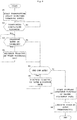
- Next, operation of the above inkjet printing system will be described with reference to
Fig. 4. Fig. 4 is a flow chart showing operation. It is assumed here that the operator has already set through the settingunit 27 printing conditions for a product with job areas PA to be printed from now on, and has already selected through the settingunit 27 discrete flushing conditions appropriate to the printing conditions. - The
controller 25 removes the caps, not shown, from theinkjet head 13, and starts transporting the web paper WP by operating thedrive rollers - The process is branched upon completion of transport through the stabilizing distance. The above step S1 and this step S2 correspond to the process between transporting distance L0 and transporting distance L1 in
Fig. 3 . - The flushing
controller 26 branches the process based on whether the transport speed is on the increase, which is determined from the pulse signal of therotary encoder 23. When the transport speed is on the increase, step S4 is executed to carry out discrete flushing at the first discharge rate. These steps S3 and S4 correspond to the process between transport distance L1 and transport distance L2 inFig. 3 . - When the pulse signal of the
rotary encoder 23 indicates completion of the increase in the transport speed, the flushingcontroller 26 branches the process based on whether the transport distance indicates the pre-job area BPA preceding the job areas PA. When the pre-job area BPA is indicated, step S6 is executed to carry out discrete flushing at the third discharge rate. These steps S5 and S6 correspond to the process between transport distance L2 and transport distance L3 inFig. 3 . - When the pulse signal of the
rotary encoder 23 indicates completion of the increase in the transport speed, and the transport distance indicates a job area PA, the flushingcontroller 26 carries out discrete flushing at the second discharge rate. This step S7 corresponds to each of the processes between transport distance L3 and transporting distance L4, transport distance L4 and transport distance L5, transport distance L5 and transport distance L6, and so on. - The controller, when it determines from the transport distance indicated by the pulse signal of the
rotary encoder 23 that the process is completed for all the job areas PA, operates thedrive rollers - According to this embodiment, when carrying out discrete flushing, the flushing
controller 26 sets for the acceleration area ACA the first discharge rate A1 as discharge rate of ink droplets per unit area in discrete flushing. The plurality ofdischarge portions 19 of theinkjet head 13 are covered by the caps before start of printing. Ink drying usually proceeds in thedischarge portions 19 after these caps are removed and until arrival of the pre-job area BPA and job areas PA which are constant speed areas. However, defective discharge can be prevented by carrying out the discrete flushing also for the acceleration area ACA. Further, for the job areas PA among the pre-job area BPA and job areas PA which are constant speed areas, the flushingcontroller 26 sets the second discharge rate A2 lower than the first discharge rate A1, as discharge rate of ink droplets per unit area in discrete flushing. Consequently, defective discharge can be prevented while inhibiting lowering of printing quality for a printed product. Since no flushing page is used, contamination of the interior of the apparatus due to flushing can be prevented without consuming extra printing paper, and a post-processing can be carried out without requiring extra time and effort. - Further, for the pre-job area BPA, the flushing
controller 26 sets the third discharge rate A3 between the first discharge rate A1 and the second discharge rate A2, as discharge rate of ink droplets per unit area in discrete flushing. Since this step can discharge a relatively large quantity of ink droplet immediately before the job areas PA for printing, defective discharge can be eliminated immediately before start of printing. Therefore, printing in the job areas PA can be carried out with high quality. - This invention is not limited to the foregoing embodiment, but may be modified as follows:
- (1) In the foregoing embodiment, the
rotary encoder 23 has been described as an example of transport speed detector. This invention is not limited to such construction as long as the transport speed of web paper WP can be detected. - (2) In the foregoing embodiment, the third discharge rate A3 is set to the discrete flushing for the pre-job area BPA. Depending on printing conditions or the characteristics of ink, this discharge rate may be made equal to the first discharge rate A1 for the acceleration area ACA. Alternatively, depending on printing conditions or the characteristics of ink, discrete flushing may be carried out for the pre-job area BPA at the second discharge rate A2 set for the job areas PA.
- (3) The foregoing embodiment has been described taking an apparatus that performs simplex printing for example, but this invention is applicable also to an apparatus that performs duplex printing. With the latter apparatus, when pages for flushing are provided between job areas PA, line flushing may be carried out for one side, and the above-described discrete flushing for the other side. This can prevent defective discharge resulting from leaving one side blank, in order to avoid inconveniences such as swelling and defacement of web paper WP which may result from line flushing done for both sides.
- This invention may be embodied in other specific forms without departing from the scope of the claims, accordingly, reference should be made to the appended claims, rather than to the foregoing specification, as indicating the scope of the invention.
Claims (15)
- An inkjet printing apparatus (3) for carrying out printing on a printing medium by discharging ink thereto, comprising:a transport speed detector for detecting transport speed of the printing medium transported continuously;an inkjet head (13) having a plurality of discharge portions (19) arranged in a width direction of the printing medium for discharging ink droplets from the discharge portions to the printing medium to print on the printing medium; anda flushing controller (26) having a function to control discharge of the ink droplets from the inkjet head for carrying out discrete flushing for discretely discharging the ink droplets on the printing medium from the discharge portions in order to prevent defective discharge from the discharge portions, wherein the flush controller functions in such a way that, for an acceleration area of the printing medium where the transport speed detector detects an increase in transport speed from a stop state until the transport speed reaches printing speed before printing, a first discharge rate is set as discharge rate of the ink droplets per unit time for the discharge flushing, and for a constant speed area of the printing medium where the transport speed detector detects a substantially constant transport speed during printing, a second discharge rate lower than the first discharge rate is set as discharge rate of the ink droplets per unit time for the discharge flushing.
- The inkjet printing apparatus (3) according to claim 1, wherein the flushing controller (26) is arranged to increase discharge frequency of the ink droplets for the acceleration area.
- The inkjet printing apparatus (3) according to claim 1, wherein the flushing controller (26) is arranged to increase size or set high discharge frequency of the ink droplets for the acceleration area.
- The inkjet printing apparatus (3) according to claim 1, wherein, for a pre-printing area of the printing medium during a period before carrying out printing immediately after completion of the increase in the transport speed of the printing medium, which period occurs while the transport speed detector detects the substantially constant transport speed, the flushing controller (26) is arranged to set a third discharge rate that is less than the first discharge rate but greater than the second discharge rate as discharge rate of the ink droplets per unit time for the discharge flushing.
- The inkjet printing apparatus (3) according to claim 2, wherein, for a pre-printing area of the printing medium during a period before carrying out printing immediately after completion of the increase in the transport speed of the printing medium, which period occurs while the transport speed detector detects the substantially constant transport speed, the flushing controller (26) is arranged to set a third discharge rate that is less than the first discharge rate but greater than the second discharge rate as discharge rate of the ink droplets per unit time for the discharge flushing.
- The inkjet printing apparatus (3) according to claim 3, wherein, for a pre-printing area of the printing medium during a period before carrying out printing immediately after completion of the increase in the transport speed of the printing medium, which period occurs while the transport speed detector detects the substantially constant transport speed, the flushing controller (26) is arranged to set a third discharge rate that is less than the first discharge rate but greater than the second discharge rate as discharge rate of the ink droplets per unit time for the discharge flushing.
- The inkjet printing apparatus (3) according to claim 1, wherein the transport speed detector is a rotary encoder attached to a transport roller by which the printing medium is transported.
- The inkjet printing apparatus (3) according to claim 2, wherein the transport speed detector is a rotary encoder attached to a transport roller by which the printing medium is transported.
- The inkjet printing apparatus (3) according to claim 3, wherein the transport speed detector is a rotary encoder attached to a transport roller by which the printing medium is transported.
- A flushing method for use with an inkjet printing apparatus (3), comprising the steps of:detecting transport speed of a printing medium transported continuously; andcarrying out discrete flushing for discretely discharging ink droplets on the printing medium from an inkjet head having a plurality of discharge portions arranged in a width direction of the printing medium in order to prevent defective discharge of ink droplets from the discharge portions;wherein, for an acceleration area of the printing medium where transport speed increases from a stop state until the transport speed reaches printing speed before printing, the discrete flushing is carried out at a first discharge rate set as discharge rate of the ink droplets per unit time; andfor a constant speed area of the printing medium where transport speed is substantially constant during printing, the discrete flushing is carried out at a second discharge rate set as discharge rate of the ink droplets per unit time to be lower than the first discharge rate.
- The flushing method according to claim 10, wherein the step of carrying out the discrete flushing at the first discharge rate increases discharge frequency of the ink droplets for the acceleration area.
- The flushing method according to claim 10, wherein the step of carrying out the discrete flushing at the first discharge rate increases size or sets high discharge frequency of the ink droplets for the acceleration area.
- The flushing method according to claim 10, wherein, for a pre-printing area of the printing medium during a period before carrying out printing immediately after completion of the increase in the transport speed of the printing medium, which period occurs while the transport speed is substantially constant, the step of carrying out the discrete flushing at the second discharge rate sets a third discharge rate that is less than the first discharge rate but greater than the second discharge rate as discharge rate of the ink droplets per unit time for the discharge flushing.
- The flushing method according to claim 11, wherein, for a pre-printing area of the printing medium during a period before carrying out printing immediately after completion of the increase in the transport speed of the printing medium, which period occurs while the transport speed is substantially constant, the step of carrying out the discrete flushing at the second discharge rate sets a third discharge rate that is less than the first discharge rate but greater than the second discharge rate as discharge rate of the ink droplets per unit time for the discharge flushing.
- The flushing method according to claim 12, wherein, for a pre-printing area of the printing medium during a period before carrying out printing immediately after completion of the increase in the transport speed of the printing medium, which period occurs while the transport speed is substantially constant, the step of carrying out the discrete flushing at the second discharge rate sets a third discharge rate that is less than the first discharge rate but greater than the second discharge rate as discharge rate of the ink droplets per unit time for the discharge flushing.
Applications Claiming Priority (1)
| Application Number | Priority Date | Filing Date | Title |
|---|---|---|---|
| JP2015145850A JP6612076B2 (en) | 2015-07-23 | 2015-07-23 | Inkjet printing apparatus and flushing method thereof |
Publications (2)
| Publication Number | Publication Date |
|---|---|
| EP3121012A1 EP3121012A1 (en) | 2017-01-25 |
| EP3121012B1 true EP3121012B1 (en) | 2019-11-06 |
Family
ID=56411510
Family Applications (1)
| Application Number | Title | Priority Date | Filing Date |
|---|---|---|---|
| EP16179387.2A Active EP3121012B1 (en) | 2015-07-23 | 2016-07-14 | Inkjet printing apparatus and a flushing method therefor |
Country Status (3)
| Country | Link |
|---|---|
| US (1) | US9987847B2 (en) |
| EP (1) | EP3121012B1 (en) |
| JP (1) | JP6612076B2 (en) |
Families Citing this family (3)
| Publication number | Priority date | Publication date | Assignee | Title |
|---|---|---|---|---|
| WO2018174886A1 (en) * | 2017-03-23 | 2018-09-27 | Hewlett-Packard Development Company, L.P. | Using nozzle idle time to determine maintenance printing fluid ejection |
| WO2020159503A1 (en) * | 2019-01-30 | 2020-08-06 | Hewlett-Packard Development Company, L.P. | Safety zone for a maintenance task |
| JP2022148134A (en) * | 2021-03-24 | 2022-10-06 | 株式会社Screenホールディングス | Printer and maintenance method of the same |
Family Cites Families (16)
| Publication number | Priority date | Publication date | Assignee | Title |
|---|---|---|---|---|
| JP4693648B2 (en) * | 2005-03-23 | 2011-06-01 | キヤノンファインテック株式会社 | Inkjet printing apparatus and preliminary ejection control method thereof |
| JP2007076156A (en) * | 2005-09-14 | 2007-03-29 | Brother Ind Ltd | Printer |
| JP2008149703A (en) * | 2006-11-23 | 2008-07-03 | Ricoh Co Ltd | Image forming apparatus and printed matter |
| JP5056326B2 (en) | 2007-10-09 | 2012-10-24 | ブラザー工業株式会社 | Inkjet printer |
| JP5707828B2 (en) * | 2010-09-30 | 2015-04-30 | セイコーエプソン株式会社 | Control method of liquid ejecting apparatus |
| JP5772072B2 (en) * | 2011-03-07 | 2015-09-02 | セイコーエプソン株式会社 | Fluid ejection device, flushing method, and flushing program |
| JP5510368B2 (en) * | 2011-03-15 | 2014-06-04 | ブラザー工業株式会社 | Liquid ejection device |
| JP5845749B2 (en) * | 2011-09-12 | 2016-01-20 | 株式会社リコー | Image forming apparatus |
| US8506046B2 (en) * | 2011-09-23 | 2013-08-13 | Infoprint Solutions Company Llc | Inkjet nozzle flushing mechanism |
| JP5787447B2 (en) * | 2012-03-28 | 2015-09-30 | 株式会社Screenホールディングス | Method for controlling conveyance of print medium in inkjet printing apparatus and inkjet printing apparatus |
| JP6102210B2 (en) * | 2012-11-20 | 2017-03-29 | セイコーエプソン株式会社 | Printing device |
| JP6409261B2 (en) * | 2013-09-17 | 2018-10-24 | 株式会社リコー | Apparatus and system |
| JP6238734B2 (en) * | 2013-12-26 | 2017-11-29 | キヤノン株式会社 | Control device, control method, and program |
| DE102014106424A1 (en) * | 2014-05-08 | 2015-11-12 | Océ Printing Systems GmbH & Co. KG | Method for controlling vibration cycles in the printing operation of an ink printing system with at least one printing device |
| JP2016215445A (en) * | 2015-05-18 | 2016-12-22 | 株式会社リコー | Liquid discharging apparatus and program |
| JP6575153B2 (en) * | 2015-06-08 | 2019-09-18 | 株式会社リコー | Device for discharging liquid |
-
2015
- 2015-07-23 JP JP2015145850A patent/JP6612076B2/en active Active
-
2016
- 2016-07-14 EP EP16179387.2A patent/EP3121012B1/en active Active
- 2016-07-19 US US15/213,982 patent/US9987847B2/en active Active
Non-Patent Citations (1)
| Title |
|---|
| None * |
Also Published As
| Publication number | Publication date |
|---|---|
| JP2017024287A (en) | 2017-02-02 |
| EP3121012A1 (en) | 2017-01-25 |
| US20170021628A1 (en) | 2017-01-26 |
| JP6612076B2 (en) | 2019-11-27 |
| US9987847B2 (en) | 2018-06-05 |
Similar Documents
| Publication | Publication Date | Title |
|---|---|---|
| US20080030535A1 (en) | Image recording apparatus, ink pre-jetting method and storage medium storing control program for pre-jetting ink | |
| EP3121012B1 (en) | Inkjet printing apparatus and a flushing method therefor | |
| JP2010000699A (en) | Inkjet recording device | |
| JP2018051765A (en) | Substrate processing device and substrate processing method | |
| JP2017218238A (en) | Printer | |
| JP5256963B2 (en) | Printing apparatus and printing method | |
| JP2016002662A (en) | Recording device and correction method | |
| US20170098143A1 (en) | Registration correction for continuous printing | |
| EP3381848B1 (en) | Apparatus for and method of processing base material | |
| US8888222B2 (en) | Liquid ejection apparatus that recovers ejection performance suitably based on a time interval between one image formation and another image formation | |
| US11130344B2 (en) | Printing apparatus and printing method | |
| JP2009226839A (en) | Image recording device | |
| JP6262964B2 (en) | Image recording apparatus and image recording method | |
| JP6366945B2 (en) | Printing control apparatus, printing apparatus, inkjet printing apparatus, and printing method | |
| US8864270B2 (en) | Method to execute a pause function during printing operation in an ink print apparatus | |
| JP2009214492A (en) | Inkjet recorder, image forming system and image forming program | |
| JP2019055570A (en) | Printing apparatus and printing method | |
| JP6390958B2 (en) | Recording unit discharge position adjusting apparatus and image forming apparatus | |
| JP7196643B2 (en) | Liquid ejector | |
| EP3351392B1 (en) | Inkjet printer | |
| CN112440559A (en) | Image forming apparatus with a toner supply device | |
| JP2006123522A (en) | Image forming apparatus | |
| WO2021200117A1 (en) | Inkjet printing device | |
| JP2020006523A (en) | Inkjet printer | |
| JP2015136821A (en) | Image forming apparatus and image formation method |
Legal Events
| Date | Code | Title | Description |
|---|---|---|---|
| PUAI | Public reference made under article 153(3) epc to a published international application that has entered the european phase |
Free format text: ORIGINAL CODE: 0009012 |
|
| STAA | Information on the status of an ep patent application or granted ep patent |
Free format text: STATUS: THE APPLICATION HAS BEEN PUBLISHED |
|
| AK | Designated contracting states |
Kind code of ref document: A1 Designated state(s): AL AT BE BG CH CY CZ DE DK EE ES FI FR GB GR HR HU IE IS IT LI LT LU LV MC MK MT NL NO PL PT RO RS SE SI SK SM TR |
|
| AX | Request for extension of the european patent |
Extension state: BA ME |
|
| STAA | Information on the status of an ep patent application or granted ep patent |
Free format text: STATUS: REQUEST FOR EXAMINATION WAS MADE |
|
| 17P | Request for examination filed |
Effective date: 20170725 |
|
| RBV | Designated contracting states (corrected) |
Designated state(s): AL AT BE BG CH CY CZ DE DK EE ES FI FR GB GR HR HU IE IS IT LI LT LU LV MC MK MT NL NO PL PT RO RS SE SI SK SM TR |
|
| GRAP | Despatch of communication of intention to grant a patent |
Free format text: ORIGINAL CODE: EPIDOSNIGR1 |
|
| STAA | Information on the status of an ep patent application or granted ep patent |
Free format text: STATUS: GRANT OF PATENT IS INTENDED |
|
| INTG | Intention to grant announced |
Effective date: 20190320 |
|
| GRAJ | Information related to disapproval of communication of intention to grant by the applicant or resumption of examination proceedings by the epo deleted |
Free format text: ORIGINAL CODE: EPIDOSDIGR1 |
|
| STAA | Information on the status of an ep patent application or granted ep patent |
Free format text: STATUS: REQUEST FOR EXAMINATION WAS MADE |
|
| INTC | Intention to grant announced (deleted) | ||
| GRAP | Despatch of communication of intention to grant a patent |
Free format text: ORIGINAL CODE: EPIDOSNIGR1 |
|
| STAA | Information on the status of an ep patent application or granted ep patent |
Free format text: STATUS: GRANT OF PATENT IS INTENDED |
|
| INTG | Intention to grant announced |
Effective date: 20190715 |
|
| GRAS | Grant fee paid |
Free format text: ORIGINAL CODE: EPIDOSNIGR3 |
|
| GRAA | (expected) grant |
Free format text: ORIGINAL CODE: 0009210 |
|
| STAA | Information on the status of an ep patent application or granted ep patent |
Free format text: STATUS: THE PATENT HAS BEEN GRANTED |
|
| AK | Designated contracting states |
Kind code of ref document: B1 Designated state(s): AL AT BE BG CH CY CZ DE DK EE ES FI FR GB GR HR HU IE IS IT LI LT LU LV MC MK MT NL NO PL PT RO RS SE SI SK SM TR |
|
| REG | Reference to a national code |
Ref country code: GB Ref legal event code: FG4D |
|
| REG | Reference to a national code |
Ref country code: CH Ref legal event code: EP Ref country code: AT Ref legal event code: REF Ref document number: 1198208 Country of ref document: AT Kind code of ref document: T Effective date: 20191115 |
|
| REG | Reference to a national code |
Ref country code: IE Ref legal event code: FG4D |
|
| REG | Reference to a national code |
Ref country code: DE Ref legal event code: R096 Ref document number: 602016023631 Country of ref document: DE |
|
| REG | Reference to a national code |
Ref country code: NL Ref legal event code: MP Effective date: 20191106 |
|
| REG | Reference to a national code |
Ref country code: LT Ref legal event code: MG4D |
|
| PG25 | Lapsed in a contracting state [announced via postgrant information from national office to epo] |
Ref country code: PT Free format text: LAPSE BECAUSE OF FAILURE TO SUBMIT A TRANSLATION OF THE DESCRIPTION OR TO PAY THE FEE WITHIN THE PRESCRIBED TIME-LIMIT Effective date: 20200306 Ref country code: NL Free format text: LAPSE BECAUSE OF FAILURE TO SUBMIT A TRANSLATION OF THE DESCRIPTION OR TO PAY THE FEE WITHIN THE PRESCRIBED TIME-LIMIT Effective date: 20191106 Ref country code: NO Free format text: LAPSE BECAUSE OF FAILURE TO SUBMIT A TRANSLATION OF THE DESCRIPTION OR TO PAY THE FEE WITHIN THE PRESCRIBED TIME-LIMIT Effective date: 20200206 Ref country code: LT Free format text: LAPSE BECAUSE OF FAILURE TO SUBMIT A TRANSLATION OF THE DESCRIPTION OR TO PAY THE FEE WITHIN THE PRESCRIBED TIME-LIMIT Effective date: 20191106 Ref country code: GR Free format text: LAPSE BECAUSE OF FAILURE TO SUBMIT A TRANSLATION OF THE DESCRIPTION OR TO PAY THE FEE WITHIN THE PRESCRIBED TIME-LIMIT Effective date: 20200207 Ref country code: PL Free format text: LAPSE BECAUSE OF FAILURE TO SUBMIT A TRANSLATION OF THE DESCRIPTION OR TO PAY THE FEE WITHIN THE PRESCRIBED TIME-LIMIT Effective date: 20191106 Ref country code: LV Free format text: LAPSE BECAUSE OF FAILURE TO SUBMIT A TRANSLATION OF THE DESCRIPTION OR TO PAY THE FEE WITHIN THE PRESCRIBED TIME-LIMIT Effective date: 20191106 Ref country code: FI Free format text: LAPSE BECAUSE OF FAILURE TO SUBMIT A TRANSLATION OF THE DESCRIPTION OR TO PAY THE FEE WITHIN THE PRESCRIBED TIME-LIMIT Effective date: 20191106 Ref country code: BG Free format text: LAPSE BECAUSE OF FAILURE TO SUBMIT A TRANSLATION OF THE DESCRIPTION OR TO PAY THE FEE WITHIN THE PRESCRIBED TIME-LIMIT Effective date: 20200206 Ref country code: SE Free format text: LAPSE BECAUSE OF FAILURE TO SUBMIT A TRANSLATION OF THE DESCRIPTION OR TO PAY THE FEE WITHIN THE PRESCRIBED TIME-LIMIT Effective date: 20191106 |
|
| PG25 | Lapsed in a contracting state [announced via postgrant information from national office to epo] |
Ref country code: RS Free format text: LAPSE BECAUSE OF FAILURE TO SUBMIT A TRANSLATION OF THE DESCRIPTION OR TO PAY THE FEE WITHIN THE PRESCRIBED TIME-LIMIT Effective date: 20191106 Ref country code: IS Free format text: LAPSE BECAUSE OF FAILURE TO SUBMIT A TRANSLATION OF THE DESCRIPTION OR TO PAY THE FEE WITHIN THE PRESCRIBED TIME-LIMIT Effective date: 20200306 Ref country code: HR Free format text: LAPSE BECAUSE OF FAILURE TO SUBMIT A TRANSLATION OF THE DESCRIPTION OR TO PAY THE FEE WITHIN THE PRESCRIBED TIME-LIMIT Effective date: 20191106 |
|
| PG25 | Lapsed in a contracting state [announced via postgrant information from national office to epo] |
Ref country code: AL Free format text: LAPSE BECAUSE OF FAILURE TO SUBMIT A TRANSLATION OF THE DESCRIPTION OR TO PAY THE FEE WITHIN THE PRESCRIBED TIME-LIMIT Effective date: 20191106 |
|
| PG25 | Lapsed in a contracting state [announced via postgrant information from national office to epo] |
Ref country code: ES Free format text: LAPSE BECAUSE OF FAILURE TO SUBMIT A TRANSLATION OF THE DESCRIPTION OR TO PAY THE FEE WITHIN THE PRESCRIBED TIME-LIMIT Effective date: 20191106 Ref country code: DK Free format text: LAPSE BECAUSE OF FAILURE TO SUBMIT A TRANSLATION OF THE DESCRIPTION OR TO PAY THE FEE WITHIN THE PRESCRIBED TIME-LIMIT Effective date: 20191106 Ref country code: CZ Free format text: LAPSE BECAUSE OF FAILURE TO SUBMIT A TRANSLATION OF THE DESCRIPTION OR TO PAY THE FEE WITHIN THE PRESCRIBED TIME-LIMIT Effective date: 20191106 Ref country code: RO Free format text: LAPSE BECAUSE OF FAILURE TO SUBMIT A TRANSLATION OF THE DESCRIPTION OR TO PAY THE FEE WITHIN THE PRESCRIBED TIME-LIMIT Effective date: 20191106 Ref country code: EE Free format text: LAPSE BECAUSE OF FAILURE TO SUBMIT A TRANSLATION OF THE DESCRIPTION OR TO PAY THE FEE WITHIN THE PRESCRIBED TIME-LIMIT Effective date: 20191106 |
|
| REG | Reference to a national code |
Ref country code: DE Ref legal event code: R097 Ref document number: 602016023631 Country of ref document: DE |
|
| REG | Reference to a national code |
Ref country code: AT Ref legal event code: MK05 Ref document number: 1198208 Country of ref document: AT Kind code of ref document: T Effective date: 20191106 |
|
| PG25 | Lapsed in a contracting state [announced via postgrant information from national office to epo] |
Ref country code: SM Free format text: LAPSE BECAUSE OF FAILURE TO SUBMIT A TRANSLATION OF THE DESCRIPTION OR TO PAY THE FEE WITHIN THE PRESCRIBED TIME-LIMIT Effective date: 20191106 Ref country code: SK Free format text: LAPSE BECAUSE OF FAILURE TO SUBMIT A TRANSLATION OF THE DESCRIPTION OR TO PAY THE FEE WITHIN THE PRESCRIBED TIME-LIMIT Effective date: 20191106 |
|
| PLBE | No opposition filed within time limit |
Free format text: ORIGINAL CODE: 0009261 |
|
| STAA | Information on the status of an ep patent application or granted ep patent |
Free format text: STATUS: NO OPPOSITION FILED WITHIN TIME LIMIT |
|
| 26N | No opposition filed |
Effective date: 20200807 |
|
| PG25 | Lapsed in a contracting state [announced via postgrant information from national office to epo] |
Ref country code: SI Free format text: LAPSE BECAUSE OF FAILURE TO SUBMIT A TRANSLATION OF THE DESCRIPTION OR TO PAY THE FEE WITHIN THE PRESCRIBED TIME-LIMIT Effective date: 20191106 Ref country code: AT Free format text: LAPSE BECAUSE OF FAILURE TO SUBMIT A TRANSLATION OF THE DESCRIPTION OR TO PAY THE FEE WITHIN THE PRESCRIBED TIME-LIMIT Effective date: 20191106 |
|
| PG25 | Lapsed in a contracting state [announced via postgrant information from national office to epo] |
Ref country code: IT Free format text: LAPSE BECAUSE OF FAILURE TO SUBMIT A TRANSLATION OF THE DESCRIPTION OR TO PAY THE FEE WITHIN THE PRESCRIBED TIME-LIMIT Effective date: 20191106 |
|
| PG25 | Lapsed in a contracting state [announced via postgrant information from national office to epo] |
Ref country code: MC Free format text: LAPSE BECAUSE OF FAILURE TO SUBMIT A TRANSLATION OF THE DESCRIPTION OR TO PAY THE FEE WITHIN THE PRESCRIBED TIME-LIMIT Effective date: 20191106 |
|
| REG | Reference to a national code |
Ref country code: CH Ref legal event code: PL |
|
| REG | Reference to a national code |
Ref country code: BE Ref legal event code: MM Effective date: 20200731 |
|
| PG25 | Lapsed in a contracting state [announced via postgrant information from national office to epo] |
Ref country code: LU Free format text: LAPSE BECAUSE OF NON-PAYMENT OF DUE FEES Effective date: 20200714 Ref country code: LI Free format text: LAPSE BECAUSE OF NON-PAYMENT OF DUE FEES Effective date: 20200731 Ref country code: CH Free format text: LAPSE BECAUSE OF NON-PAYMENT OF DUE FEES Effective date: 20200731 |
|
| PG25 | Lapsed in a contracting state [announced via postgrant information from national office to epo] |
Ref country code: BE Free format text: LAPSE BECAUSE OF NON-PAYMENT OF DUE FEES Effective date: 20200731 |
|
| PG25 | Lapsed in a contracting state [announced via postgrant information from national office to epo] |
Ref country code: IE Free format text: LAPSE BECAUSE OF NON-PAYMENT OF DUE FEES Effective date: 20200714 |
|
| PG25 | Lapsed in a contracting state [announced via postgrant information from national office to epo] |
Ref country code: TR Free format text: LAPSE BECAUSE OF FAILURE TO SUBMIT A TRANSLATION OF THE DESCRIPTION OR TO PAY THE FEE WITHIN THE PRESCRIBED TIME-LIMIT Effective date: 20191106 Ref country code: MT Free format text: LAPSE BECAUSE OF FAILURE TO SUBMIT A TRANSLATION OF THE DESCRIPTION OR TO PAY THE FEE WITHIN THE PRESCRIBED TIME-LIMIT Effective date: 20191106 Ref country code: CY Free format text: LAPSE BECAUSE OF FAILURE TO SUBMIT A TRANSLATION OF THE DESCRIPTION OR TO PAY THE FEE WITHIN THE PRESCRIBED TIME-LIMIT Effective date: 20191106 |
|
| PG25 | Lapsed in a contracting state [announced via postgrant information from national office to epo] |
Ref country code: MK Free format text: LAPSE BECAUSE OF FAILURE TO SUBMIT A TRANSLATION OF THE DESCRIPTION OR TO PAY THE FEE WITHIN THE PRESCRIBED TIME-LIMIT Effective date: 20191106 |
|
| P01 | Opt-out of the competence of the unified patent court (upc) registered |
Effective date: 20230515 |
|
| PGFP | Annual fee paid to national office [announced via postgrant information from national office to epo] |
Ref country code: FR Payment date: 20230620 Year of fee payment: 8 |
|
| PGFP | Annual fee paid to national office [announced via postgrant information from national office to epo] |
Ref country code: GB Payment date: 20230601 Year of fee payment: 8 |
|
| PGFP | Annual fee paid to national office [announced via postgrant information from national office to epo] |
Ref country code: DE Payment date: 20230531 Year of fee payment: 8 |