EP3120821A1 - Medical positioning and retaining device - Google Patents
Medical positioning and retaining device Download PDFInfo
- Publication number
- EP3120821A1 EP3120821A1 EP16001555.8A EP16001555A EP3120821A1 EP 3120821 A1 EP3120821 A1 EP 3120821A1 EP 16001555 A EP16001555 A EP 16001555A EP 3120821 A1 EP3120821 A1 EP 3120821A1
- Authority
- EP
- European Patent Office
- Prior art keywords
- carrier unit
- stator core
- locking pin
- axial end
- end position
- Prior art date
- Legal status (The legal status is an assumption and is not a legal conclusion. Google has not performed a legal analysis and makes no representation as to the accuracy of the status listed.)
- Granted
Links
- 238000011144 upstream manufacturing Methods 0.000 claims description 32
- 230000008878 coupling Effects 0.000 claims description 22
- 238000010168 coupling process Methods 0.000 claims description 22
- 238000005859 coupling reaction Methods 0.000 claims description 22
- 239000007819 coupling partner Substances 0.000 abstract description 34
- 238000011161 development Methods 0.000 description 3
- 230000018109 developmental process Effects 0.000 description 3
- 238000009434 installation Methods 0.000 description 3
- 230000003993 interaction Effects 0.000 description 2
- 239000012791 sliding layer Substances 0.000 description 2
- 239000000654 additive Substances 0.000 description 1
- 230000000996 additive effect Effects 0.000 description 1
- 230000015572 biosynthetic process Effects 0.000 description 1
- 150000001875 compounds Chemical class 0.000 description 1
- 238000013461 design Methods 0.000 description 1
- 238000012544 monitoring process Methods 0.000 description 1
- 238000011017 operating method Methods 0.000 description 1
- 238000012552 review Methods 0.000 description 1
Images

Classifications
-
- A—HUMAN NECESSITIES
- A61—MEDICAL OR VETERINARY SCIENCE; HYGIENE
- A61G—TRANSPORT, PERSONAL CONVEYANCES, OR ACCOMMODATION SPECIALLY ADAPTED FOR PATIENTS OR DISABLED PERSONS; OPERATING TABLES OR CHAIRS; CHAIRS FOR DENTISTRY; FUNERAL DEVICES
- A61G12/00—Accommodation for nursing, e.g. in hospitals, not covered by groups A61G1/00 - A61G11/00, e.g. trolleys for transport of medicaments or food; Prescription lists
- A61G12/002—Supply appliances, e.g. columns for gas, fluid, electricity supply
- A61G12/004—Supply appliances, e.g. columns for gas, fluid, electricity supply mounted on the ceiling
-
- A—HUMAN NECESSITIES
- A61—MEDICAL OR VETERINARY SCIENCE; HYGIENE
- A61G—TRANSPORT, PERSONAL CONVEYANCES, OR ACCOMMODATION SPECIALLY ADAPTED FOR PATIENTS OR DISABLED PERSONS; OPERATING TABLES OR CHAIRS; CHAIRS FOR DENTISTRY; FUNERAL DEVICES
- A61G13/00—Operating tables; Auxiliary appliances therefor
- A61G13/10—Parts, details or accessories
- A61G13/101—Clamping means for connecting accessories to the operating table
-
- A—HUMAN NECESSITIES
- A61—MEDICAL OR VETERINARY SCIENCE; HYGIENE
- A61G—TRANSPORT, PERSONAL CONVEYANCES, OR ACCOMMODATION SPECIALLY ADAPTED FOR PATIENTS OR DISABLED PERSONS; OPERATING TABLES OR CHAIRS; CHAIRS FOR DENTISTRY; FUNERAL DEVICES
- A61G15/00—Operating chairs; Dental chairs; Accessories specially adapted therefor, e.g. work stands
- A61G15/14—Dental work stands; Accessories therefor
- A61G15/16—Storage, holding or carrying means for dental handpieces or the like
-
- A—HUMAN NECESSITIES
- A61—MEDICAL OR VETERINARY SCIENCE; HYGIENE
- A61G—TRANSPORT, PERSONAL CONVEYANCES, OR ACCOMMODATION SPECIALLY ADAPTED FOR PATIENTS OR DISABLED PERSONS; OPERATING TABLES OR CHAIRS; CHAIRS FOR DENTISTRY; FUNERAL DEVICES
- A61G7/00—Beds specially adapted for nursing; Devices for lifting patients or disabled persons
- A61G7/05—Parts, details or accessories of beds
- A61G7/0503—Holders, support devices for receptacles, e.g. for drainage or urine bags
-
- F—MECHANICAL ENGINEERING; LIGHTING; HEATING; WEAPONS; BLASTING
- F16—ENGINEERING ELEMENTS AND UNITS; GENERAL MEASURES FOR PRODUCING AND MAINTAINING EFFECTIVE FUNCTIONING OF MACHINES OR INSTALLATIONS; THERMAL INSULATION IN GENERAL
- F16M—FRAMES, CASINGS OR BEDS OF ENGINES, MACHINES OR APPARATUS, NOT SPECIFIC TO ENGINES, MACHINES OR APPARATUS PROVIDED FOR ELSEWHERE; STANDS; SUPPORTS
- F16M11/00—Stands or trestles as supports for apparatus or articles placed thereon Stands for scientific apparatus such as gravitational force meters
- F16M11/20—Undercarriages with or without wheels
- F16M11/2007—Undercarriages with or without wheels comprising means allowing pivoting adjustment
- F16M11/2014—Undercarriages with or without wheels comprising means allowing pivoting adjustment around a vertical axis
-
- F—MECHANICAL ENGINEERING; LIGHTING; HEATING; WEAPONS; BLASTING
- F16—ENGINEERING ELEMENTS AND UNITS; GENERAL MEASURES FOR PRODUCING AND MAINTAINING EFFECTIVE FUNCTIONING OF MACHINES OR INSTALLATIONS; THERMAL INSULATION IN GENERAL
- F16M—FRAMES, CASINGS OR BEDS OF ENGINES, MACHINES OR APPARATUS, NOT SPECIFIC TO ENGINES, MACHINES OR APPARATUS PROVIDED FOR ELSEWHERE; STANDS; SUPPORTS
- F16M13/00—Other supports for positioning apparatus or articles; Means for steadying hand-held apparatus or articles
- F16M13/02—Other supports for positioning apparatus or articles; Means for steadying hand-held apparatus or articles for supporting on, or attaching to, an object, e.g. tree, gate, window-frame, cycle
- F16M13/027—Ceiling supports
-
- A—HUMAN NECESSITIES
- A61—MEDICAL OR VETERINARY SCIENCE; HYGIENE
- A61G—TRANSPORT, PERSONAL CONVEYANCES, OR ACCOMMODATION SPECIALLY ADAPTED FOR PATIENTS OR DISABLED PERSONS; OPERATING TABLES OR CHAIRS; CHAIRS FOR DENTISTRY; FUNERAL DEVICES
- A61G2203/00—General characteristics of devices
- A61G2203/70—General characteristics of devices with special adaptations, e.g. for safety or comfort
- A61G2203/76—General characteristics of devices with special adaptations, e.g. for safety or comfort for nesting or stacking
-
- A—HUMAN NECESSITIES
- A61—MEDICAL OR VETERINARY SCIENCE; HYGIENE
- A61G—TRANSPORT, PERSONAL CONVEYANCES, OR ACCOMMODATION SPECIALLY ADAPTED FOR PATIENTS OR DISABLED PERSONS; OPERATING TABLES OR CHAIRS; CHAIRS FOR DENTISTRY; FUNERAL DEVICES
- A61G2203/00—General characteristics of devices
- A61G2203/70—General characteristics of devices with special adaptations, e.g. for safety or comfort
- A61G2203/78—General characteristics of devices with special adaptations, e.g. for safety or comfort for clamping
Definitions
- the invention relates to a medical positioning and holding device, in particular for positioning and holding medical-technical elements in a clinical environment.
- the object of the present invention is thus to provide a device, in particular for receiving and positioning medical-technical elements, which has a particularly high reliability and allows a variable and secure arrangement of multiple carrier units with low installation costs.
- a medical-technical positioning and holding device has a base element, a plurality of carrier units and a closure element, wherein the components are also referred to collectively below as coupling partners.
- the base element provides the connection of the positioning and holding device to a supporting structure, for example a ceiling of an operating room, and for this purpose has corresponding fastening means, which are designed, for example, as screws.
- the supporting structure is not part of the present invention.
- the base member has a receiving portion with an undercut area at a lower axial end. The lower axial end in this case represents the supporting structure of the opposite end of the base member.
- each carrier unit of the positioning and holding device has a stator core with an upper axial end and a lower one axial end up.
- the upper axial end represents the coupled state of the support structure facing the end and the lower axial end in the coupled state of the end facing away from the supporting structure.
- the stator core has at the upper axial end of an engagement portion with a Studentsgreifungssegment and at the lower axial End in the same way as the base member on a receiving portion with an undercut area.
- the arrangement of the carrier units within the positioning and holding device according to the invention is such that a first carrier unit is coupled to the base member or an upstream carrier unit, wherein the stator core of the first carrier unit inserted into the corresponding receiving portion of the base member or the stator core of the upstream carrier unit and in the inserted position in the corresponding receiving portion is rotated.
- the rotation takes place to such an extent that the overlapping segment of the engagement section of the stator core of the first carrier unit engages behind the undercut region of the receiving section of the base element or of the stator core of the upstream carrier unit and in this way also in the axial direction a positive connection between the first carrier unit and the base element, or between the first Carrier unit and the upstream carrier unit is provided.
- the deployable positive locking is referred to in this context as the coupling end position, in which the first carrier unit has assumed its final position relative to the base element or the upstream carrier unit.
- coupling end position is subsequently used in the same way for all coupling partners and in this case describes the final assembly position of the respective coupling partner in the positioning and holding device.
- the first carrier unit also has, as well as all other carrier units in the positioning and holding device, at least one locking pin, which is axially movably receivable in a corresponding locking pin receptacle of the respective stator core.
- the carrier units Preferably, the carrier units have three radially offset locking pin and corresponding to three locking pin receptacles.
- the arrangement of the at least one locking pin in the respective stator core according to the invention is such that it can be brought in the coupling end position in an axial end position.
- an axial end position of the locking pin engages a coupling partner in the upstream coupling partner that twisting of the coupling partner is prevented from the upstream coupling partner.
- the engagement of the locking pin takes place here in a designated recess portion of the base member or the stator core of the upstream carrier unit, wherein the recess portion is formed for example as a hole or incision in the respective receiving portion of the base member or the stator core of the upstream carrier unit.
- the arrangement of the locking pin in the respective stator core is further such that it is fixed by a stator core of a downstream carrier unit or by the closing element form-fit in its axial end position.
- each carrier unit of a positioning and holding device has an annular body which surrounds the associated stator core and can be rotated about it.
- Each annular body in this case has an attachment portion to which one or more medical units can be fastened. Fixing is to be understood in the broad sense, so that the medical unit can also be designed as a structural unit.
- medical units are in particular understood as technical devices for carrying out an operating procedure in an operating room, which can be, for example, surgical lights, monitoring monitors or operating or storage devices.
- the medical units themselves are not part of the positioning and holding device according to the invention. Due to the rotatability of the respective ring body, an independent pivotability of the medical unit accommodated on the respective carrying unit is made possible in the present case.
- the positioning and holding device according to the invention has the technological advantage that a particularly simple and also tool-free assembly and disassembly is made possible by the formation of the coupling partner.
- Another advantage is the high variability and expandability of the number of wear units.
- the stator cores of the carrier units have at one axial end a fixed radial flange, which is designed such that the corresponding annular body is guided at one of its axial ends by the radial flange at least axially.
- a fixed radial flange Through the radial flange of a stator core is in the present case a one-sided positive engagement with the annular body and, accordingly, an axial position determination of the annular body available.
- the radial flanges of coupled coupling partners are further configured so that the annular body of a carrier unit is axially guided at its respective other axial end by the annular flange of a pre or a downstream carrier unit.
- a positive engagement acting on both sides with the annular body of the respective carrier unit and thus a positional determination of the annular body on both sides are effected.
- the leadership of the respective annular body during its rotation, wherein the radial flanges for this purpose may additionally have a sliding layer.
- a stator core of a respective carrier unit can have a circumferential bearing element, for example in the form of a sliding bearing ring, by which a unilateral positive connection with the respective annular body is provided on which the correspondingly associated annular body can be guided.
- the radial flanges can dispense as a particular advantage to additional elements for guiding and position fixing the ring body to the associated stator cores and thus a cost-effective provision of the carrier units be enabled. Furthermore, a simple disassembly of stator core and ring body can be provided by this development. Preferably, the ring body is simply pushed axially onto the stator core, wherein it is held in this axial position without additive alone by the coupling of the coupling partner.
- an advantageous variant of the positioning and holding device provides that the locking pin of an upstream carrier unit in a position other than its axial end position prevents the introduction of a coupling end position of a downstream carrier unit or of the closing element.
- the locking pin is in this case designed so that it terminates only in its axial end position with the lower end of the locking pin receptacle of the associated coupling partner.
- the locking pin receptacle of a coupling partner and the corresponding recessed portion of the respective upstream coupling partner not in a coupling end position and thus not corresponding to each other, the locking pin can not be inserted into the recess portion and thus not be brought into its axial end position.
- the locking pin then protrudes over at the lower end of the stator core and thus blocks the way in which a stator core of a downstream carrier element or of the terminating element leads to a coupling.
- the particular advantage consists in the high reliability, since the installation of additional coupling partners requires that the locking pin is properly in the axial end position and thus engaged position.
- the locking pin receptacle and the locking pin of a carrier unit are designed such that the locking pin receptacle has a female threaded section and the locking pin has an externally threaded section have, wherein the locking pin by means of rotation in the locking pin receptacle in its axial end position can be brought.
- the rotation of the locking pin in this case causes it to be clamped in its axial end position against the bottom of the recess of the respective upstream coupling partner and in this way the Schugreifungsab songs the upstream coupling partner is braced against the overlap segment of the subsequent coupling partner.
- the interconnected coupling partners can be set axially free of play with each other.
- this also further improves the high level of operational reliability in that a possible loosening of the tension on the first does not lead to a failure of the connection and the second is noticeable by the user through a game occurring, so that measures can be initiated for review.
- the attachment portions of the annular body of the respective carrier units are formed in a further advantageous embodiment of the positioning and holding device as support arms.
- the attachment portions allow a particularly flexible reception of the medical units, wherein the support arms can also be formed telescopically or with joints, so that - a variable-length recording of the medical units can be provided by this.
- an advantageous development of the positioning and holding device provides that the Schugreifungsabitese and / or the overlapping segments of the coupling partners are formed Mogliedrig and distributed radially over the circumference of the respective receiving or engaging portion.
- the Hintergreifungsabitese and / or the overlapping segments are formed in three parts, wherein the individual members are arranged at an angle of about 120 degrees offset from each other.
- An angle of about 120 degrees is understood to mean a range of 90 degrees to 150 degrees, the size of three angles being distributed in the said range so that the sum of them is 360 degrees.
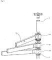
- Fig. 1 shows the medical positioning and holding device in one embodiment with a base member 1, three support units 2.1, 2.2 and 2.3, and a closure element. 3
- the elements mentioned are also referred to below as coupling partners.
- the support units 2.1 to 2.3 each have a mounting portion 14, wherein the mounting portions are presently designed as a pivotable support arms for receiving medical devices.
- the base element 1 is fastened to a supporting structure (not shown) by means of fastening elements (not shown), wherein the supporting structure is presently designed as a ceiling of an operating room on which the positioning and holding device is arranged.
- the carrier units 2 can be connected to one another and to the base element 1 and the closing element 3.
- each carrier unit 2 has a stationary stator core 6 and an annular body 8 rotatably connected thereto, the annular bodies 8 having the receiving portions 14.
- each stator core 6 of a carrier unit 2 in the present case has an engagement section 9, each with an overlapping segment 10 and a receiving section 11, each with an undercut region 12.
- Fig. 3 shows a first carrier unit 2.1 and connected thereto, downstream carrier unit 2.3 and the end element 3.
- connection of two carrier units 2 with each other is based here Fig. 3 explained, wherein the connecting analog for the connection of a carrier unit 2 with the base element 1 or the end element 3 is made.
- the engaging portion 9.3 of the stator core 6.3 of the downstream carrier unit 2.3 is inserted into the receiving portion 11.1 of the first carrier unit 2.1 and twisted in this so that the overlap segment of the downstream carrier unit 2.3 2.3.3 engages behind the undercut region 12.1 of the first carrier unit 2.1.
- an axially releasable, releasable, positive connection between the carrier units 2.1 and 2.3 is provided.
- the compound which can be provided in this way is referred to herein as the coupling end position.
- each support unit 2 at least one locking pin 7, which is arranged axially displaceably in a corresponding locking pin receptacle 13 of the respective stator core 6 ,
- the locking pin 7.3 is moved axially until it reaches its end position that engages in a corresponding recess portion 17 of the first carrier unit 2.1 and so provides the radial positive connection between the carrier units 2.1 and 2.3.
- each carrier unit 2 in the present case has three locking pins 7, which are received in corresponding locking pin receptacles 13 of the stator cores 6.
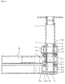
- the Fig. 2 shows the positioning and holding device in an embodiment with three support units 2.1 to 2.3, which are connected to each other and at an upper end to the base member 1 and at an opposite, lower end to the closing element 3.
- a first carrier unit 2.1 is connected to an upstream carrier unit 2.2 and to a downstream carrier unit 2.3, the upstream carrier unit 2.2 in turn being connected to the base element 1 and the downstream carrier unit 2.3 being connected to the terminating element 3.
- the connection between the base member 1 and the upstream support unit 2.2 is made, as already above in connection with Fig. 3 quoted, analogous to the connection of the first carrier unit 2.1 with the downstream carrier unit 2.3.
- the engagement portion 9.2 with the overlap segment 10.2 is hereby inserted into the receiving portion 4 of the base member 1 and rotated in this far enough that the overlap segment 10.2 engages behind the undercut region 5 of the base member 1 and is provided in the coupling end position of the axial positive connection between these two coupling partners.
- the locking pins 7.2 of the upstream carrier unit 2.2 are brought into their axial end position in the coupling end position, in which they engage in corresponding recesses (not shown explicitly for clarity) of the base element 1 and thus provide the radial positive connection between the two coupling partners.
- the locking pins 7.2 of the upstream carrier unit 2.2 are fixed by the stator ring 6.1 of the adjoining thereto, the first carrier unit 2.1.
- the connections between the first carrier unit 2.1 and the upstream carrier unit 2.2 and between the first carrier unit 2.1 and the downstream carrier unit 2.3 and between the downstream carrier unit 2.3 and the closing element 3 are provided.
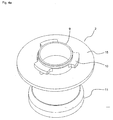
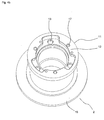
- FIGS. 4a and 4b In the present case, a preferred embodiment variant of the carrier units 2 is shown, wherein the overlapping segments 10 and the undercut regions 12 are multi-membered and each have three links. In this way, a simple connection of the coupling partner is made possible while providing a secure, axial positive locking.
- FIG. 1 to 4b a further advantageous variant of the invention, in which the support units 2 each have a radial flange 15 at one end, through which, as in Fig. 2 shown, the annular body 8 of the support units 2 are held axially in position.
- the locking pin 7 of the support units 2 are presently designed according to an equally advantageous embodiment such that they have an external threaded portion, by means of which the locking pin 7 in a corresponding internal threaded portion of the corresponding locking pin receptacle 13 rotatable and can be brought into its axial end position.
- In the axial end position in this case is a tension of the respective locking pin 7 against the bottom of each corresponding recess 17 through which leads as a particular advantage that the undercut region 12 of a coupling partner and the overlap segment 10 of a downstream coupling partner braced against each other and the coupling partners thus axially can be determined without play to each other.
Abstract
Die Erfindung betrifft eine medizintechnische Positionier- und Haltevorrichtung, aufweisend mehrere Kopplungspartner, wobei die Kopplungspartner als ein Basiselement (1), eine Mehrzahl Trägereinheiten (2) sowie ein Abschlusselement (3) ausgebildet sind und wobei die Kopplungspartner formschlüssig miteinander verbunden und mittels Sperrbolzen (7) gegen unerwünschtes Verdrehen gesichert sind.The invention relates to a medical positioning and holding device, comprising a plurality of coupling partners, wherein the coupling partners as a base member (1), a plurality of carrier units (2) and a closing element (3) are formed and wherein the coupling partners positively connected to each other and by means of locking pins (7 ) are secured against undesired twisting.
Description
Die Erfindung betrifft eine medizintechnische Positionier- und Haltevorrichtung, insbesondere zur Positionierung und Halterung medizintechnischer Elemente in einem klinischen Umfeld.The invention relates to a medical positioning and holding device, in particular for positioning and holding medical-technical elements in a clinical environment.
Aus dem Stand der Technik sind bereits Vorrichtungen bekannt, welche eine Aufnahme technischer Geräte an schwenkbaren Tragarmen ermöglichen.
In diesem Zusammenhang beschreibt beispielsweise die Druckschrift
Eine solche Ausbildung der Befestigungsvorrichtung ermöglicht zwar ein unabhängiges Schwenken der einzelnen Tragarme, bedingt jedoch zwingend eine Festlegung der Länge des Grundkörpers auf die gewünschte Anzahl der übereinanderliegenden Lagerhülsen.
Dementsprechend kann durch eine solche Befestigungsvorrichtung nur eine eingeschränkte Variabilität hinsichtlich der Anzahl der Tragarme und hinsichtlich einer nachträglichen Ergänzung weiterer Tragarme bereitgestellt werden.Devices are already known from the prior art, which allow a recording of technical equipment on pivotable support arms.
In this context, for example, the document describes
Although such a design of the fastening device allows independent pivoting of the individual support arms, but necessarily requires a determination of the length of the body to the desired number of superimposed bearing sleeves.
Accordingly, only a limited variability in terms of the number of support arms and with respect to a subsequent addition of further support arms can be provided by such a fastening device.
Eine weitere Lösung, insbesondere zur Aufnahme medizinischer Geräte in einem Operationssaal an mehreren, unabhängig voneinander schwenkbaren Tragarmen, wird in der Druckschrift
Eine solche Aufnahmevorrichtung ermöglicht somit zwar einerseits eine variable und im Nachhinein erweiterbare Anordnung der Tragarme, andererseits erfordert diese Lösung jedoch durch die Verschraubung der die Tragarme aufnehmenden Module einen erhöhten Montageaufwand sowie zusätzliche Sicherungselemente zum Verhindern eines unabsichtlichen Lösens der Verschraubungen.Another solution, in particular for receiving medical devices in an operating room at a plurality of independently pivotable support arms, is in the
Although such a recording device thus allows on the one hand a variable and expandable in retrospect arrangement of the support arms, on the other hand, however, this solution requires by the screw of the support arms receiving Modules increased installation costs and additional security elements to prevent inadvertent loosening of the fittings.
Die Aufgabe der vorliegenden Erfindung bildet es somit, eine Vorrichtung, insbesondere zur Aufnahme und Positionierung medizintechnischer Elemente bereitzustellen, welche eine besonders hohe Betriebssicherheit aufweist und eine variable und sichere Anordnung mehrerer Trägereinheiten bei gleichzeitig geringem Montageaufwand ermöglicht.The object of the present invention is thus to provide a device, in particular for receiving and positioning medical-technical elements, which has a particularly high reliability and allows a variable and secure arrangement of multiple carrier units with low installation costs.
Die Aufgabe wird durch eine Positionier- und Haltevorrichtung mit den im Patentanspruch 1 aufgeführten Merkmalen gelöst. Bevorzugte Weiterbildungen ergeben sich aus den Unteransprüchen.The object is achieved by a positioning and holding device with the features listed in
Eine erfindungsgemäße medizintechnische Positionier- und Haltevorrichtung weist ein Basiselement, eine Mehrzahl Trägereinheiten sowie ein Abschlusselement auf, wobei die Komponenten nachfolgend auch zusammengefasst als Kopplungspartner bezeichnet werden.A medical-technical positioning and holding device according to the invention has a base element, a plurality of carrier units and a closure element, wherein the components are also referred to collectively below as coupling partners.
Das Basiselement stellt vorliegend die Verbindung der Positionier- und Haltevorrichtung zu einer tragenden Struktur, beispielsweise einer Decke eines Operationssaals, bereit und weist hierzu entsprechende Befestigungsmittel auf, welche zum Beispiel als Schrauben ausgebildet sind.
Die tragende Struktur stellt hierbei keinen Bestandteil der vorliegenden Erfindung dar.
Das Basiselement weist an einem unteren axialen Ende einen Aufnahmeabschnitt mit einem Hinterschneidungsbereich auf. Das untere axiale Ende stellt hierbei das der tragenden Struktur gegenüberliegende Ende des Basiselements dar.In the present case, the base element provides the connection of the positioning and holding device to a supporting structure, for example a ceiling of an operating room, and for this purpose has corresponding fastening means, which are designed, for example, as screws.
The supporting structure is not part of the present invention.
The base member has a receiving portion with an undercut area at a lower axial end. The lower axial end in this case represents the supporting structure of the opposite end of the base member.
Erfindungsgemäß weist zudem jede Trägereinheit der Positionier- und Haltevorrichtung einen Statorkern mit einem oberen axialen Ende und einem unteren axialen Ende auf. Das obere axiale Ende stellt das in gekoppeltem Zustand der tragenden Struktur zugewandte Ende und das untere axiale Ende das in gekoppeltem Zustand der von der tragenden Struktur abgewandte Ende dar. Der Statorkern weist an dem oberen axialen Ende einen Eingriffsabschnitt mit einem Übergreifungssegment und an dem unteren axialen Ende in gleicher Weise wie das Basiselement einen Aufnahmeabschnitt mit einem Hinterschneidungsbereich auf.In addition, according to the invention, each carrier unit of the positioning and holding device has a stator core with an upper axial end and a lower one axial end up. The upper axial end represents the coupled state of the support structure facing the end and the lower axial end in the coupled state of the end facing away from the supporting structure. The stator core has at the upper axial end of an engagement portion with a Übergreifungssegment and at the lower axial End in the same way as the base member on a receiving portion with an undercut area.
Die Anordnung der Trägereinheiten innerhalb der Positionier- und Haltevorrichtung erfolgt erfindungsgemäß derart, dass eine erste Trägereinheit mit dem Basiselement oder einer vorgelagerten Trägereinheit gekoppelt wird, wobei der Statorkern der ersten Trägereinheit in den korrespondierenden Aufnahmeabschnitt des Basiselements oder des Statorkerns der vorgelagerten Trägereinheit eingeführt und in der eingeführten Lage in dem entsprechenden Aufnahmeabschnitt verdreht wird. Die Verdrehung erfolgt soweit, dass das Übergreifungssegment des Eingriffsabschnitts des Statorkerns der ersten Trägereinheit den Hinterschneidungsbereich des Aufnahmeabschnitts des Basiselements oder des Statorkerns der vorgelagerten Trägereinheit hintergreift und auf diese Weise auch in axialer Richtung ein Formschluss zwischen der ersten Trägereinheit und dem Basiselement, beziehungsweise zwischen der ersten Trägereinheit und der vorgelagerten Trägereinheit bereitgestellt wird.
Der bereitstellbare Formschluss wird in diesem Zusammenhang als Kopplungsendlage bezeichnet, in welcher die erste Trägereinheit ihre finale Position relativ zu dem Basiselement oder der vorgelagerten Trägereinheit eingenommen hat.The arrangement of the carrier units within the positioning and holding device according to the invention is such that a first carrier unit is coupled to the base member or an upstream carrier unit, wherein the stator core of the first carrier unit inserted into the corresponding receiving portion of the base member or the stator core of the upstream carrier unit and in the inserted position in the corresponding receiving portion is rotated. The rotation takes place to such an extent that the overlapping segment of the engagement section of the stator core of the first carrier unit engages behind the undercut region of the receiving section of the base element or of the stator core of the upstream carrier unit and in this way also in the axial direction a positive connection between the first carrier unit and the base element, or between the first Carrier unit and the upstream carrier unit is provided.
The deployable positive locking is referred to in this context as the coupling end position, in which the first carrier unit has assumed its final position relative to the base element or the upstream carrier unit.
Der Begriff Kopplungsendlage wird nachfolgend für alle Kopplungspartner in gleicher Weise verwendet und beschreibt hierbei die Endmontagelage des jeweiligen Kopplungspartners in der Positionier- und Haltevorrichtung.The term coupling end position is subsequently used in the same way for all coupling partners and in this case describes the final assembly position of the respective coupling partner in the positioning and holding device.
Die erste Trägereinheit weist zudem, ebenso wie alle weiteren Trägereinheiten in der Positionier- und Haltevorrichtung, mindestens einen Sperrbolzen auf, welcher in einer entsprechenden Sperrbolzenaufnahme des jeweiligen Statorkerns axial beweglich aufnehmbar ist.
Vorzugsweise weisen die Trägereinheiten drei radial versetzt angeordnete Sperrbolzen und entsprechend drei Sperrbolzenaufnahmen auf.The first carrier unit also has, as well as all other carrier units in the positioning and holding device, at least one locking pin, which is axially movably receivable in a corresponding locking pin receptacle of the respective stator core.
Preferably, the carrier units have three radially offset locking pin and corresponding to three locking pin receptacles.
Die Anordnung des mindestens einen Sperrbolzens in dem jeweiligen Statorkern erfolgt erfindungsgemäß derart, dass dieser in der Kopplungsendlage in eine axiale Endlage bringbar ist.
In einer solchen axialen Endlage greift der Sperrbolzen eines Kopplungspartners derart in den vorgelagerten Kopplungspartner ein, dass ein Verdrehen des Kopplungspartners gegenüber dem vorgeschalteten Kopplungspartner verhindert wird.
Im Falle der ersten Trägereinheit bedeutet dies, dass deren Sperrbolzen in deren Kopplungsendlage formschlüssig in das Basiselement oder den Statorkern der vorgelagerten Trägereinheit eingreift und so die Kopplungsendlage der ersten Trägereinheit innerhalb der Positionier- und Haltevorrichtung fixiert wird.
Der Eingriff des Sperrbolzens erfolgt hierbei in einen dafür vorgesehenen Ausnehmungsabschnitt des Basiselements oder des Statorkerns der vorgelagerten Trägereinheit, wobei der Ausnehmungsabschnitt beispielsweise als Loch oder Einschnitt in dem jeweiligen Aufnahmeabschnitt des Basiselements oder des Statorkerns der vorgelagerten Trägereinheit ausgebildet ist.The arrangement of the at least one locking pin in the respective stator core according to the invention is such that it can be brought in the coupling end position in an axial end position.
In such an axial end position of the locking pin engages a coupling partner in the upstream coupling partner that twisting of the coupling partner is prevented from the upstream coupling partner.
In the case of the first carrier unit, this means that the locking pin engages positively in the coupling end position in the base member or the stator core of the upstream carrier unit and so the coupling end position of the first carrier unit is fixed within the positioning and holding device.
The engagement of the locking pin takes place here in a designated recess portion of the base member or the stator core of the upstream carrier unit, wherein the recess portion is formed for example as a hole or incision in the respective receiving portion of the base member or the stator core of the upstream carrier unit.
Die Anordnung des Sperrbolzens in dem jeweiligen Statorkern erfolgt ferner derart, dass dieser durch einen Statorkern einer nachgelagerten Trägereinheit oder durch das Abschlusselement formschlüssig in seiner axialen Endlage festgelegt wird.
Somit wird auf besonders unkomplizierte Art und Weise eine Fixierung der jeweiligen Trägereinheiten in deren Kopplungsendlage innerhalb der Positionier- und Haltevorrichtung ermöglicht, welche ausschließlich durch das Aneinanderkoppeln der einzelnen Kopplungspartner und dementsprechend ohne zusätzliches Anordnen weiterer Sicherungselemente bereitgestellt wird.The arrangement of the locking pin in the respective stator core is further such that it is fixed by a stator core of a downstream carrier unit or by the closing element form-fit in its axial end position.
Thus, a fixation of the respective carrier units in the coupling end position within the positioning and holding device is made possible in a particularly uncomplicated way, which is provided exclusively by the coupling of the individual coupling partners and accordingly without additional arranging further securing elements.
Darüber hinaus weist jede Trägereinheit einer erfindungsgemäßen Positionier- und Haltevorrichtung einen Ringkörper auf, welcher den zugehörigen Statorkern umgreift und um diesen verdrehbar ist.
Jeder Ringkörper weist hierbei einen Befestigungsabschnitt auf, an welchem eine oder mehrere medizinische Einheiten befestigbar sind. Befestigen ist im weiten Sinne zu verstehen, so dass die medizinische Einheit auch als bauliche Einheit ausgebildet sein kann.
Unter medizinischen Einheiten werden vorliegend insbesondere technische Geräte zur Ausführung eines Operationsvorgangs in einem Operationssaal verstanden, wobei es sich beispielsweise um OP-Leuchten, Überwachungsmonitore oder Operations- oder Ablagevorrichtungen handeln kann.
Die medizinischen Einheiten selbst sind nicht Bestandteil der erfindungsgemäßen Positionier- und Haltevorrichtung.
Durch die Verdrehbarkeit des jeweiligen Ringkörpers wird vorliegend eine unabhängige Schwenkbarkeit der an der jeweiligen Trageinheit aufgenommenen, medizinischen Einheit ermöglicht.In addition, each carrier unit of a positioning and holding device according to the invention has an annular body which surrounds the associated stator core and can be rotated about it.
Each annular body in this case has an attachment portion to which one or more medical units can be fastened. Fixing is to be understood in the broad sense, so that the medical unit can also be designed as a structural unit.
In the present case, medical units are in particular understood as technical devices for carrying out an operating procedure in an operating room, which can be, for example, surgical lights, monitoring monitors or operating or storage devices.
The medical units themselves are not part of the positioning and holding device according to the invention.
Due to the rotatability of the respective ring body, an independent pivotability of the medical unit accommodated on the respective carrying unit is made possible in the present case.
Die erfindungsgemäße Positionier- und Haltevorrichtung bietet den technologischen Vorteil, dass durch die Ausbildung der Kopplungspartner eine besonders einfache und zudem werkzeuglose Montage sowie Demontage ermöglicht wird.The positioning and holding device according to the invention has the technological advantage that a particularly simple and also tool-free assembly and disassembly is made possible by the formation of the coupling partner.
Ein weiterer Vorteil besteht in der hohen Variabilität und Erweiterbarkeit der Anzahl der Trageinheiten.Another advantage is the high variability and expandability of the number of wear units.
Ferner besteht ein Vorteil in der besonders hohen Betriebssicherheit, da durch die Verkopplung der Formschlüsse von Eingriffsabschnitt und Aufnahmeabschnitt, von Sperrbolzen und von nachfolgendem Kopplungspartner eine Lösung einer Trägereinheit prinzipbedingt ohne zusätzlichen Sicherungsmittel ausgeschlossen wird, sofern nicht der letzte Kopplungspartner, also das Abschlusselement, gelöst ist. Zudem besteht der Vorzug einer Ankündigung einer etwaigen Störung, da ein Lösen des Abschlusselements visuell unmittelbar erkennbar ist. Dies kann zusätzlich durch eine auffällige Farbgebung des sonst verdeckt liegenden unteren Endes der letzten Trägereinheit unterstützt werden.Furthermore, there is an advantage in the particularly high reliability, since the coupling of the form fit of engaging portion and receiving portion, locking pin and subsequent coupling partner a solution of a carrier unit principle is excluded without additional securing means, unless the last coupling partner, so the end element is solved , In addition, the advantage of an announcement of any Disturbance, since a release of the closing element is visually immediately recognizable. This can be further supported by a striking color of the otherwise hidden lower end of the last carrier unit.
In einer besonders vorteilhaften Weiterbildung der Erfindung weisen die Statorkerne der Trägereinheiten an einem axialen Ende einen feststehenden Radialflansch auf, welcher derart ausgebildet ist, dass der entsprechende Ringkörper an einem seiner axialen Enden durch den Radialflansch zumindest axial geführt wird.
Durch den Radialflansch eines Statorkerns ist vorliegend ein einseitig wirkender Formschluss mit dem Ringkörper und dementsprechend eine axiale Lagefestlegung des Ringkörpers bereitstellbar.In a particularly advantageous embodiment of the invention, the stator cores of the carrier units have at one axial end a fixed radial flange, which is designed such that the corresponding annular body is guided at one of its axial ends by the radial flange at least axially.
Through the radial flange of a stator core is in the present case a one-sided positive engagement with the annular body and, accordingly, an axial position determination of the annular body available.
Die Radialflansche miteinander gekoppelter Kopplungspartner sind ferner so ausgebildet, dass der Ringkörper einer Trägereinheit an seinem jeweils anderen axialen Ende durch den Ringflansch einer vor- oder einer nachgeschalteten Trägereinheit axial geführt wird.
Durch das Zusammenwirken der Radialflansche wird im Ergebnis ein beidseitig wirkender Formschluss mit dem Ringkörper der jeweiligen Trägereinheit und somit eine beidseitige Lagefestlegung des Ringkörpers bewirkt.
Gleichzeitig erfolgt auf den jeweils untenliegenden Radialflanschen die Führung der jeweiligen Ringkörper während deren Verdrehens, wobei die Radialflansche zu diesem Zweck zusätzlich über eine Gleitschicht verfügen können. Alternativ zu einer Gleitschicht kann ein Statorkern einer jeweiligen Trägereinheit ein umlaufendes Lagerelement, beispielsweise in Form eines Gleitlagerrings, aufweisen, durch welches ein einseitiger Formschluss mit dem jeweiligen Ringkörper bereitgestellt auf welchem der entsprechend zugehörige Ringkörper führbar ist.The radial flanges of coupled coupling partners are further configured so that the annular body of a carrier unit is axially guided at its respective other axial end by the annular flange of a pre or a downstream carrier unit.
As a result of the interaction of the radial flanges, a positive engagement acting on both sides with the annular body of the respective carrier unit and thus a positional determination of the annular body on both sides are effected.
At the same time carried on the respective underlying radial flanges, the leadership of the respective annular body during its rotation, wherein the radial flanges for this purpose may additionally have a sliding layer. As an alternative to a sliding layer, a stator core of a respective carrier unit can have a circumferential bearing element, for example in the form of a sliding bearing ring, by which a unilateral positive connection with the respective annular body is provided on which the correspondingly associated annular body can be guided.
Aufgrund der Radialflansche kann als besonderer Vorteil auf zusätzliche Elemente zur Führung und Lagefestlegung der Ringkörper an den zugehörigen Statorkernen verzichtet und somit eine kostengünstige Bereitstellung der Trägereinheiten ermöglicht werden. Ferner kann durch diese Weiterbildung eine einfache Demontierbarkeit von Statorkern und Ringkörper bereitgestellt werden. Vorzugsweise wird der Ringkörper einfach axial auf den Statorkern aufgeschoben, wobei er in dieser axialen Lage ohne Zusatzmittel allein durch die Verkopplung der Kopplungspartner gehalten wird.Due to the radial flanges can dispense as a particular advantage to additional elements for guiding and position fixing the ring body to the associated stator cores and thus a cost-effective provision of the carrier units be enabled. Furthermore, a simple disassembly of stator core and ring body can be provided by this development. Preferably, the ring body is simply pushed axially onto the stator core, wherein it is held in this axial position without additive alone by the coupling of the coupling partner.
Des Weiteren sieht eine vorteilhafte Variante der Positionier- und Haltevorrichtung vor, dass der Sperrbolzen einer vorgelagerten Trägereinheit in einer anderen Lage als seiner axialen Endlage das Herbeiführen einer Kopplungsendlage einer nachgelagerten Trägereinheit oder des Abschlusselements verhindert. Der Sperrbolzen ist hierbei so ausgebildet, dass dieser nur in seiner axialen Endlage mit dem unteren Ende der Sperrbolzenaufnahme des zugehörigen Kopplungspartners abschließt.Furthermore, an advantageous variant of the positioning and holding device provides that the locking pin of an upstream carrier unit in a position other than its axial end position prevents the introduction of a coupling end position of a downstream carrier unit or of the closing element. The locking pin is in this case designed so that it terminates only in its axial end position with the lower end of the locking pin receptacle of the associated coupling partner.
Liegen die Sperrbolzenaufnahme eines Kopplungspartners und der entsprechende Ausnehmungsabschnitt des jeweils vorgelagerten Kopplungspartners nicht in einer Kopplungsendlage und damit nicht korrespondierend übereinander, kann der Sperrbolzen nicht in den Ausnehmungsabschnitt eingeführt und somit nicht in seine axiale Endlage gebracht werden. Der Sperrbolzen steht dann an dem unteren Ende des Statorkerns über und versperrt auf diese Weise einem Statorkern eines nachgelagerten Trägerelements oder des Abschlusselements den Weg zur Durchführung einer Kopplung.If the locking pin receptacle of a coupling partner and the corresponding recessed portion of the respective upstream coupling partner not in a coupling end position and thus not corresponding to each other, the locking pin can not be inserted into the recess portion and thus not be brought into its axial end position. The locking pin then protrudes over at the lower end of the stator core and thus blocks the way in which a stator core of a downstream carrier element or of the terminating element leads to a coupling.
Der besondere Vorteil besteht in der hohen Betriebssicherheit, da die Montage weiterer Kopplungspartner bedingt, dass der Sperrbolzen ordnungsgemäß in axialer Endlage und damit Eingriffslage steht.The particular advantage consists in the high reliability, since the installation of additional coupling partners requires that the locking pin is properly in the axial end position and thus engaged position.
Gemäß einer vorteilhaften Variante der Erfindung sind die Sperrbolzenaufnahme und der Sperrbolzen einer Trägereinheit derart ausgebildet, dass die Sperrbolzenaufnahme einen Innengewindeabschnitt und der Sperrbolzen einen Außengewindeabschnitt aufweisen, wobei der Sperrbolzen mittels Verdrehen in der Sperrbolzenaufnahme in seine axiale Endlage bringbar ist.
Das Verdrehen des Sperrbolzens bewirkt hierbei, dass diese in seiner axialen Endlage gegen den Grund der Ausnehmung des jeweils vorgelagerten Kopplungspartners verspannt wird und auf diese Weise der Hintergreifungsabschnitt des vorgelagerten Kopplungspartners gegen das Übergreifungssegment des nachfolgenden Kopplungspartners verspannbar ist.According to an advantageous variant of the invention, the locking pin receptacle and the locking pin of a carrier unit are designed such that the locking pin receptacle has a female threaded section and the locking pin has an externally threaded section have, wherein the locking pin by means of rotation in the locking pin receptacle in its axial end position can be brought.
The rotation of the locking pin in this case causes it to be clamped in its axial end position against the bottom of the recess of the respective upstream coupling partner and in this way the Hintergreifungsabschnitt the upstream coupling partner is braced against the overlap segment of the subsequent coupling partner.
Somit können als besonderer Vorteil durch den Sperrbolzen die miteinander verbundenen Kopplungspartner axial spielfrei zueinander festgelegt werden.Thus, as a particular advantage of the locking pin, the interconnected coupling partners can be set axially free of play with each other.
Zudem wird auch hierdurch die hohe Betriebssicherheit weiter verbessert in dem eine etwaige Lockerung der Verspannung zum ersten nicht zu einem Versagen der Verbindung führt und zum zweiten durch den Nutzer durch ein auftretendes Spiel bemerkbar ist, so dass Maßnahmen zur Überprüfung eingeleitet werden können.In addition, this also further improves the high level of operational reliability in that a possible loosening of the tension on the first does not lead to a failure of the connection and the second is noticeable by the user through a game occurring, so that measures can be initiated for review.
Die Befestigungsabschnitte der Ringkörper der jeweiligen Trägereinheiten sind in einer weiteren vorteilhaften Ausbildung der Positionier- und Haltevorrichtung als Tragarme ausgebildet.The attachment portions of the annular body of the respective carrier units are formed in a further advantageous embodiment of the positioning and holding device as support arms.
In Form der Tragarme ermöglichen die Befestigungsabschnitte eine besonders flexible Aufnahme der medizinischen Einheiten, wobei die Tragarme auch teleskopartig oder mit Gelenken ausgebildet sein können, sodass durch diese eine - längenveränderliche Aufnahme der medizinischen Einheiten bereitstellbar ist.In the form of the support arms, the attachment portions allow a particularly flexible reception of the medical units, wherein the support arms can also be formed telescopically or with joints, so that - a variable-length recording of the medical units can be provided by this.
Darüber hinaus sieht eine vorteilhafte Weiterbildung der Positionier- und Haltevorrichtung vor, dass die Hintergreifungsabschnitte und/oder die Übergreifungssegmente der Kopplungspartner mehrgliedrig ausgebildet und über den Umfang des jeweiligen Aufnahme- oder Eingriffsabschnittes radial verteilt angeordnet sind.In addition, an advantageous development of the positioning and holding device provides that the Hintergreifungsabschnitte and / or the overlapping segments of the coupling partners are formed mehrgliedrig and distributed radially over the circumference of the respective receiving or engaging portion.
Vorzugsweise sind die Hintergreifungsabschnitte und/oder die Übergreifungssegmente dreigliedrig ausgebildet, wobei die einzelnen Glieder in einem Winkel von etwa 120 Grad versetzt zueinander angeordnet sind. Als Winkel von etwa 120 Grad wird ein Bereich von 90 Grad bis 150 Grad verstanden, wobei sich die Größe drei Winkel im genannten Bereich so verteilt ist, dass in deren Summe 360 Grad vorliegen.Preferably, the Hintergreifungsabschnitte and / or the overlapping segments are formed in three parts, wherein the individual members are arranged at an angle of about 120 degrees offset from each other. An angle of about 120 degrees is understood to mean a range of 90 degrees to 150 degrees, the size of three angles being distributed in the said range so that the sum of them is 360 degrees.
Durch die Mehrgliedrigkeit wird in diesem Zusammenhang eine besonders komfortable und gleichzeitig mechanisch hoch belastbare Kopplung der Kopplungspartner in der Positionier- und Haltevorrichtung ermöglicht.Due to the multi-memberedness, a particularly comfortable and at the same time mechanically highly loadable coupling of the coupling partners in the positioning and holding device is made possible in this context.
Die erfindungsgemäße, medizinische Positionier- und Haltevorrichtung wird als Ausführungsbeispiel anhand von
- Fig. 1
- Explosionsdarstellung
- Fig. 2
- Seitenansicht geschnitten
- Fig. 3
- Detailansicht Trägereinheiten
- Fig. 4a
- Schrägansicht Trägereinheit Oberseite
- Fig. 4b
- Schrägansicht Trägereinheit Unterseite
- Fig. 1
- exploded view
- Fig. 2
- Side view cut
- Fig. 3
- Detail view of carrier units
- Fig. 4a
- Oblique view carrier unit top
- Fig. 4b
- Oblique view of carrier unit underside
Die genannten Elemente werden nachfolgend auch als Kopplungspartner bezeichnet.
Die Trägereinheiten 2.1 bis 2.3 weisen jeweils einen Befestigungsabschnitt 14 auf, wobei die Befestigungsabschnitte vorliegend als schwenkbare Tragarme zur Aufnahme medizinischer Geräte ausgebildet sind.
Das Basiselement 1 wird vorliegend mittels Befestigungselementen (nicht dargestellt) an einer tragenden Struktur (nicht dargestellt) befestigt, wobei die tragende Struktur vorliegend als Decke eines Operationssaales ausgebildet ist, an welcher die Positionier- und Haltevorrichtung angeordnet ist.
Ferner sind die Trägereinheiten 2 miteinander sowie mit dem Basiselement 1 und dem Abschlusselement 3 verbindbar.The elements mentioned are also referred to below as coupling partners.
The support units 2.1 to 2.3 each have a mounting
In the present case, the
Furthermore, the
In
Wie
As
Zur Verbindung miteinander sowie zur Verbindung mit dem Basiselement 1 oder dem Abschlusselement 3, weist jeder Statorkern 6 einer Trägereinheit 2 vorliegend einen Eingriffsabschnitt 9 mit jeweils einem Übergreifungssegment 10 sowie einen Aufnahmeabschnitt 11 mit jeweils einem Hinterschneidungsbereich 12 auf.
Zur besseren Veranschaulichung des Zusammenwirkens der einzelnen Abschnitte wird zusätzlich auf
To better illustrate the interaction of the individual sections is in addition to
Das Verbinden zweier Trägereinheiten 2 miteinander wird vorliegend anhand
Zur Verbindung der in
Zur Bereitstellung eines ebenfalls für eine feste Verbindung der Trägereinheiten 2 miteinander sowie mit dem Basiselement 1 oder dem Abschlusselement 3 erforderlichen, radialen Formschlusses, weist jede Trägereinheit 2 mindestens einen Sperrbolzen 7 auf, welcher in einer entsprechenden Sperrbolzenaufnahme 13 des jeweiligen Statorkerns 6 axial verschieblich angeordnet ist.
In der Kopplungsendlage, vorliegend der nachgelagerten Trägereinheit 2.3, wird deren Sperrbolzen 7.3 axial bis zum Erreichen seiner Endlage soweit verschoben, dass dieser in einen entsprechend korrespondierenden Ausnehmungsabschnitt 17 der ersten Trägereinheit 2.1 eingreift und so den radialen Formschluss zwischen den Trägereinheiten 2.1 und 2.3 bereitstellt.
Die Fixierung des jeweiligen Sperrbolzens 7 in seiner axialen Endlage erfolgt vorliegend durch den jeweils nachgelagerten Kopplungspartner, im Falle der Trägereinheiten 2 durch den jeweiligen Statorkern 6 und im Falle des Abschlusselements 3 durch dieses selbst.
Zur Optimierung des radialen Formschlusses weist jede Trägereinheit 2 vorliegend drei Sperrbolzen 7 auf, welche in entsprechenden Sperrbolzenaufnahmen 13 der Statorkerne 6 aufgenommen sind.To provide a likewise for a firm connection of the
In the coupling end position, in this case the downstream carrier unit 2.3, the locking pin 7.3 is moved axially until it reaches its end position that engages in a
The fixation of the respective locking pin 7 in its axial end position takes place here by the respective downstream coupling partner, in the case of the
To optimize the radial positive connection, each
Die
Hierbei ist eine erste Trägereinheit 2.1 mit einer vorgelagerten Trägereinheit 2.2 und mit einer nachgelagerten Trägereinheit 2.3 verbunden, wobei die vorgelagerte Trägereinheit 2.2 wiederum mit dem Basiselement 1 und die nachgelagerte Trägereinheit 2.3 mit dem Abschlusselement 3 verbunden ist.
Die Verbindung zwischen dem Basiselement 1 und der vorgelagerten Trägereinheit 2.2 erfolgt, wie oben bereits im Zusammenhang mit
Der Eingriffsabschnitt 9.2 mit dem Übergreifungssegment 10.2 wird hierbei in den Aufnahmeabschnitt 4 des Basiselements 1 eingeführt und in diesem soweit verdreht, dass das Übergreifungssegment 10.2 den Hinterschneidungsbereich 5 des Basiselements 1 hintergreift und so in der Kopplungsendlage der axiale Formschluss zwischen diesen beiden Kopplungspartnern bereitgestellt wird. Gleichzeitig werden in der Kopplungsendlage die Sperrbolzen 7.2 der vorgelagerten Trägereinheit 2.2 in ihre axiale Endlage gebracht, in welcher diese in entsprechende Ausnehmungen (der Übersichtlichkeit halber nicht explizit dargestellt) des Basiselements 1 eingreifen und so den radialen Formschluss zwischen beiden Kopplungspartnern bereitstellen.
In ihrer axialen Endlage werden die Sperrbolzen 7.2 der vorgelagerten Trägereinheit 2.2 durch den Statorring 6.1 der sich an diese anschließenden, ersten Trägereinheit 2.1 fixiert.
Auf gleiche Weise werden die Verbindungen zwischen der ersten Trägereinheit 2.1 und der vorgelagerten Trägereinheit 2.2 sowie zwischen der ersten Trägereinheit 2.1 und der nachgelagerten Trägereinheit 2.3 und zwischen der nachgelagerten Trägereinheit 2.3 und dem Abschlusselement 3 bereitgestellt.The
In this case, a first carrier unit 2.1 is connected to an upstream carrier unit 2.2 and to a downstream carrier unit 2.3, the upstream carrier unit 2.2 in turn being connected to the
The connection between the
The engagement portion 9.2 with the overlap segment 10.2 is hereby inserted into the receiving
In its axial end position, the locking pins 7.2 of the upstream carrier unit 2.2 are fixed by the stator ring 6.1 of the adjoining thereto, the first carrier unit 2.1.
In the same way, the connections between the first carrier unit 2.1 and the upstream carrier unit 2.2 and between the first carrier unit 2.1 and the downstream carrier unit 2.3 and between the downstream carrier unit 2.3 and the
Die
Zudem zeigen die
Hierbei erfolgt die Lagefestlegung eines Ringkörpers 8 nach oben durch den Ringflansch 15 der zugehörigen Trägereinheit 2 und nach unten durch den Ringflansch 15 der jeweils nachgelagerten Trägereinheit 2.In addition, the show
Here, the position fixing an
Zudem sind die Sperrbolzen 7 der Trägereinheiten 2 vorliegend gemäß einer ebenso vorteilhaften Ausführungsvariante derart ausgebildet, dass diese einen Außengewindeabschnitt aufweisen, mittels dessen die Sperrbolzen 7 in einem korrespondierenden Innengewindeabschnitt der entsprechenden Sperrbolzenaufnahme 13 verdrehbar und so in ihre axiale Endlage bringbar sind.
In der axialen Endlage liegt hierbei eine Verspannung des jeweiligen Sperrbolzens 7 gegen den Grund der jeweils korrespondierenden Ausnehmung 17 vor, durch welche als besonderer Vorteil dazu führt, dass der Hinterschneidungsbereich 12 eines Kopplungspartners und das Übergreifungssegment 10 eines nachgelagerten Kopplungspartners gegeneinander verspannt und die Kopplungspartner somit axial spielfrei zueinander festgelegt werden können.In addition, the locking pin 7 of the
In the axial end position in this case is a tension of the respective locking pin 7 against the bottom of each
- 11
- Basiselementbase element
- 22
- Trägereinheitensupport units
- 2.12.1
- erste Trägereinheitfirst carrier unit
- 2.22.2
- vorgelagerte Trägereinheitupstream carrier unit
- 2.32.3
- nachgelagerte Trägereinheitdownstream carrier unit
- 33
- Abschlusselementtermination element
- 44
- Aufnahmeabschnitt BasiselementReceiving section base element
- 55
- Hinterschneidungsbereich BasiselementUndercut area base element
- 66
- Statorkernestator cores
- 6.16.1
- Statorkern erste TrägereinheitStator core first carrier unit
- 6.36.3
- Statorkern nachgelagerte TrägereinheitStator core downstream carrier unit
- 77
- Sperrbolzenlocking pin
- 7.17.1
- Sperrbolzen erste TrägereinheitLock pin first carrier unit
- 7.27.2
- Sperrbolzen vorgelagerte TrägereinheitLocking pin upstream support unit
- 7.37.3
- Sperrbolzen nachgelagerte TrägereinheitLocking pin downstream carrier unit
- 88th
- Ringkörperring body
- 99
- Eingriffsabschnitteengaging portions
- 9.19.1
- Eingriffsabschnitt erste TrägereinheitEngagement section first carrier unit
- 9.39.3
- Eingriffsabschnitt nachgelagerte TrägereinheitEngagement section downstream carrier unit
- 1010
- ÜbergreifungssegmenteÜbergreifungssegmente
- 10.110.1
- Übergreifungssegment erste TrägereinheitOverlap segment first carrier unit
- 10.210.2
- Übergreifungssegment vorgelagerte TrägereinheitOverlap segment upstream carrier unit
- 10.310.3
- Übergreifungssegment nachgelagerte TrägereinheitOverlap segment downstream carrier unit
- 1111
- Aufnahmeabschnitte TrägereinheitenReceiving sections carrier units
- 11.111.1
- Aufnahmeabschnitt erste TrägereinheitReceiving section first carrier unit
- 11.211.2
- Aufnahmeabschnitt vorgelagerte TrägereinheitReceiving portion upstream carrier unit
- 11.311.3
- Aufnahmeabschnitt nachgelagerte TrägereinheitReceiving portion downstream carrier unit
- 1212
- Hinterschneidungsbereiche TrägereinheitenUndercut areas of carrier units
- 12.112.1
- Hinterschneidungsbereich erste TrägereinheitUndercut area first carrier unit
- 12.212.2
- Hinterschneidungsbereich vorgelagerte TrägereinheitUndercutting area upstream carrier unit
- 12.312.3
- Hinterschneidungsbereich nachgelagerte TrägereinheitUndercut area downstream carrier unit
- 1313
- SperrbolzenaufnahmenLocking pin receptacles
- 13.113.1
- Sperrbolzenaufnahme erste TrägereinheitLock pin receptacle first carrier unit
- 13.213.2
- Sperrbolzenaufnahme vorgelagerte TrägereinheitLock pin receptacle upstream support unit
- 1414
- Befestigungsabschnittefixing portions
- 1515
- Radialflanscheradial flanges
- 15.115.1
- Radialflansch erste TrägereinheitRadial flange first carrier unit
- 15.315.3
- Radialflansch nachgelagerte TrägereinheitRadial flange downstream carrier unit
- 1616
- Übergreifungssegment AbschlusselementOverlap segment end element
- 1717
- Ausnehmungabschnitt erste TrägereinheitRecess portion first carrier unit
Claims (6)
aufweisend ein Basiselement (1), eine Mehrzahl Trägereinheiten (2) sowie ein Abschlusselement (3), wobei die Trägereinheiten (2) untereinander und mit dem Basiselement (1) sowie mit dem Abschlusselement (3) koppelbar sind, wobei das Basiselement (1) Befestigungsmittel zur Befestigung an einer Struktur sowie einen Aufnahmeabschnitt (4) aufweist und wobei der Aufnahmeabschnitt (4) einen Hinterschneidungsbereich (5) aufweist, und wobei jede Trägereinheit (2) einen Statorkern (6), mindestens einen Sperrbolzen (7) und einen Ringkörper (8) aufweist, wobei jeder Statorkern (6) ein oberes axiales Ende und ein unteres axiales Ende aufweist und wobei jeder Statorkern (6) an seinem oberen axialen Ende einen Eingriffsabschnitt (9) mit einem Übergreifungssegment (10) und an seinem unteren axialen Ende einen Aufnahmeabschnitt (11) mit einem Hinterschneidungsbereich (12) aufweist und wobei der Eingriffsabschnitt (9) eines Statorkerns (6) einer ersten Trägereinheit (2.1) in den Aufnahmeabschnitt (4) des Basiselements (1) oder in einen Aufnahmeabschnitt (11.2) eines Statorkerns (6.2) einer vorgelagerten Trägereinheit (2.2) einführbar und in einer eingeführten Lage verdrehbar ist, wobei durch die Verdrehung eine Kopplungsendlage bereitstellbar ist und wobei in der Kopplungsendlage ein Eingriff des Übergreifungssegments (10.1) des Eingriffsabschnitts (9.1) des Statorkerns (6.1) der ersten Trägereinheit (2.1) in den Hinterschneidungsbereich (5) des Aufnahmeabschnitts (4) des Basiselements (1) oder in einen Hinterschneidungsbereich (12.2) des Aufnahmeabschnitts (11.2) des Statorkerns (6.2) der vorgelagerten Trägereinheit (2.2) bereitstellbar ist, und wobei jeder Statorkern (6) eine Sperrbolzenaufnahme (13) aufweist, in welcher der mindestens eine Sperrbolzen (7) der jeweiligen Trägereinheit (2) aufnehmbar und in eine axiale Endlage bringbar ist, wobei mittels eines Sperrbolzens (7.1) des Statorkerns (6.1) der ersten Trägereinheit (2.1) deren Kopplungsendlage mittels eines formschlüssigen Versperrens gegen Verdrehung des Statorkerns (6.1) der ersten Trägereinheit (2.1) gegenüber dem Basiselement (1) oder dem Statorkern (6.2) der vorgelagerten Trägereinheit (2.2) bereitstellbar ist und wobei der Sperrbolzen (7.1) der ersten Trägereinheit (2.1) in seiner axialen Endlage durch einen Statorkern (6.3) einer nachgelagerten Trägereinheit (2.3) in dessen Kopplungsendlage oder durch das Abschlusselement (3) festlegbar ist, und wobei jeder Ringkörper (8) den Statorkern (6) der zugehörigen Trägereinheit (2) umgreift und um den Statorkern (6) drehbar ausgebildet ist und wobei jeder Ringkörper (8) jeweils einen Befestigungsabschnitt (14) zur Befestigung medizinischer Einheiten aufweist, und wobei das Abschlusselement (3) mit dem Statorkern (6) einer Trägereinheit (2) an dessen unterem axialen Ende verbindbar ist.Medical positioning and holding device,
comprising a base element (1), a plurality of carrier units (2) and a closure element (3), wherein the carrier units (2) can be coupled to one another and to the base element (1) and to the closure element (3), wherein the base element (1) Fastening means for attachment to a structure and a receiving portion (4) and wherein the receiving portion (4) has an undercut area (5), and wherein each carrier unit (2) has a stator core (6), at least one locking pin (7) and a ring body ( 8), wherein each stator core (6) has an upper axial end and a lower axial end, and wherein each stator core (6) has at its upper axial end an engaging portion (9) with a lap segment (10) and at its lower axial end Receiving portion (11) having an undercut region (12) and wherein the engagement portion (9) of a stator core (6) of a first carrier unit (2.1) in the receiving portion (4) of the base element (1) or in a receiving portion (11.2) of a stator core (6.2) an upstream support unit (2.2) insertable and rotatable in an inserted position, wherein by the rotation of a coupling end position is provided and wherein in the coupling end position an engagement of the overlapping segment (9.1) of the stator core (6.1) of the first carrier unit (2.1) in the undercut region (5) of the receiving section (4) of the base element (1) or in an undercut region (12.2) of the receiving section (11.2) of Stator core (6.2) of the upstream carrier unit (2.2) can be provided, and wherein each stator core (6) has a locking pin receptacle (13) in which the at least one locking pin (7) of the respective carrier unit (2) can be received and brought into an axial end position , Wherein by means of a locking pin (7.1) of the stator core (6.1) of the first carrier unit (2.1) whose coupling end position by means of a positive locking against rotation of the stator core (6.1) of the first carrier unit (2.1) relative to the base element (1) or the stator core (6.2) of the upstream carrier unit (2.2) is provided and wherein the locking pin (7.1) of the first carrier unit (2.1) in its axial end position by a stator core (6.3) of a downstream carrier unit (2.3) in the coupling end position or by the end element (3) can be fixed, and wherein each annular body (8) the stator core (6) of the associated carrier unit (2) engages around and the stator core (6) being rotatably formed, each ring body (8) having a medical unit mounting portion (14), and the end member (3) having the stator core (6) a support unit (2) at the lower axial end thereof is connectable.
wobei jeder Statorkern (6) an einem axialen Ende einen feststehenden Radialflansch (15) aufweist und wobei der Ringkörper (8) einer Trägereinheit (2) an einem ersten axialen Ende durch den Radialflansch (15) des Statorkerns (6) der zugehörigen Trägereinheit (2) und an einem zweiten axialen Ende durch den Radialflansch (15) des Statorkerns (6) einer vorgelagerten oder einer nachgelagerten Trägereinheit (2) oder durch das Basiselement (1) oder durch das Abschlusselement (3) axial geführt wird.Medical positioning and holding device according to claim 1,
wherein each stator core (6) has a stationary radial flange (15) at one axial end, and wherein the annular body (8) of a carrier unit (2) is connected at a first axial end by the radial flange (15) of the stator core (6) of the associated carrier unit (2 ) and axially guided at a second axial end by the radial flange (15) of the stator core (6) of an upstream or downstream carrier unit (2) or by the base member (1) or by the end member (3).
wobei der mindestens eine Sperrbolzen (7) einer vorgelagerten Trägereinheit (2) in einer anderen Lage als seiner axialen Endlage das Herbeiführen einer Kopplungsendlage einer nachgelagerten Trägereinheit (2) oder des Abschlusselements (3) verhindert.Medical positioning and holding device according to claim 1 or 2,
wherein the at least one locking pin (7) of an upstream carrier unit (2) in a position other than its axial end position prevents the introduction of a coupling end position of a downstream carrier unit (2) or of the closing element (3).
wobei die Sperrbolzenaufnahme (13) einer Trägereinheit (2) einen Innengewindeabschnitt und der zugehörige Sperrbolzen (7) einen Außengewindeabschnitt aufweisen und wobei der Sperrbolzen (7) in seiner axialen Endlage gegen einen korrespondierenden Grund einer Ausnehmung (17) der vorgelagerten Trägereinheit (2.2) oder des Basiselements (1) verspannbar ist.Medical positioning and holding device according to one of the preceding claims,
wherein the locking pin receptacle (13) of a carrier unit (2) has an internally threaded portion and the associated locking pin (7) has an externally threaded portion and wherein the locking pin (7) in its axial end position against a corresponding base of a recess (17) of the upstream carrier unit (2.2) or the base element (1) is clamped.
wobei die Befestigungsabschnitte (14) der Ringkörper (8) der Trägereinheiten (2) als Tragarme ausgebildet sind.Medical-technical positioning and holding device according to one of the preceding claims,
wherein the mounting portions (14) of the annular body (8) of the support units (2) are designed as support arms.
wobei die Hinterschneidungsbereiche (5) und/oder die Übergreifungssegmente (10) mehrgliedrig ausgebildet und radial verteilt angeordnet sind.Medical positioning and holding device according to one of the preceding claims,
wherein the undercut regions (5) and / or the overlap segments (10) are formed mehrgliedrig and arranged radially distributed.
Applications Claiming Priority (1)
| Application Number | Priority Date | Filing Date | Title |
|---|---|---|---|
| DE102015009336.3A DE102015009336B3 (en) | 2015-07-23 | 2015-07-23 | Medical-technical positioning and holding device |
Publications (2)
| Publication Number | Publication Date |
|---|---|
| EP3120821A1 true EP3120821A1 (en) | 2017-01-25 |
| EP3120821B1 EP3120821B1 (en) | 2018-05-09 |
Family
ID=56133295
Family Applications (1)
| Application Number | Title | Priority Date | Filing Date |
|---|---|---|---|
| EP16001555.8A Active EP3120821B1 (en) | 2015-07-23 | 2016-07-14 | Medical positioning and retaining device |
Country Status (2)
| Country | Link |
|---|---|
| EP (1) | EP3120821B1 (en) |
| DE (1) | DE102015009336B3 (en) |
Cited By (1)
| Publication number | Priority date | Publication date | Assignee | Title |
|---|---|---|---|---|
| CN109099127A (en) * | 2017-06-21 | 2018-12-28 | 舍弗勒技术股份两合公司 | Executive device and its manufacturing method |
Families Citing this family (1)
| Publication number | Priority date | Publication date | Assignee | Title |
|---|---|---|---|---|
| WO2016168453A1 (en) * | 2015-04-16 | 2016-10-20 | Medovex Corp. | Docking systems for medical devices and related devices |
Citations (6)
| Publication number | Priority date | Publication date | Assignee | Title |
|---|---|---|---|---|
| US4673154A (en) * | 1983-07-05 | 1987-06-16 | Karapita Alexander D | Suspension device |
| US4756429A (en) * | 1986-03-31 | 1988-07-12 | Liberty Diversified Industries | Carousel data holder |
| FR2711507A1 (en) * | 1993-10-25 | 1995-05-05 | Guillian Jean Louis | Adjustable wall support, in particular for medical apparatuses |
| DE20015399U1 (en) | 2000-08-17 | 2001-01-11 | Mavig Gmbh | Fastening device |
| DE10221103C1 (en) * | 2002-05-03 | 2003-10-02 | Dieter Buckow | Face plate jaw comprises an operating element, spring elements arranged between a first part supported on the operating element and a second part, half-claws supported on the second part, and a tie rod |
| DE102009047971A1 (en) | 2009-10-01 | 2011-04-07 | Dräger Medical GmbH | Suspension device and method for its assembly |
-
2015
- 2015-07-23 DE DE102015009336.3A patent/DE102015009336B3/en active Active
-
2016
- 2016-07-14 EP EP16001555.8A patent/EP3120821B1/en active Active
Patent Citations (6)
| Publication number | Priority date | Publication date | Assignee | Title |
|---|---|---|---|---|
| US4673154A (en) * | 1983-07-05 | 1987-06-16 | Karapita Alexander D | Suspension device |
| US4756429A (en) * | 1986-03-31 | 1988-07-12 | Liberty Diversified Industries | Carousel data holder |
| FR2711507A1 (en) * | 1993-10-25 | 1995-05-05 | Guillian Jean Louis | Adjustable wall support, in particular for medical apparatuses |
| DE20015399U1 (en) | 2000-08-17 | 2001-01-11 | Mavig Gmbh | Fastening device |
| DE10221103C1 (en) * | 2002-05-03 | 2003-10-02 | Dieter Buckow | Face plate jaw comprises an operating element, spring elements arranged between a first part supported on the operating element and a second part, half-claws supported on the second part, and a tie rod |
| DE102009047971A1 (en) | 2009-10-01 | 2011-04-07 | Dräger Medical GmbH | Suspension device and method for its assembly |
Cited By (2)
| Publication number | Priority date | Publication date | Assignee | Title |
|---|---|---|---|---|
| CN109099127A (en) * | 2017-06-21 | 2018-12-28 | 舍弗勒技术股份两合公司 | Executive device and its manufacturing method |
| CN109099127B (en) * | 2017-06-21 | 2023-08-25 | 舍弗勒技术股份两合公司 | Actuator and method for manufacturing the same |
Also Published As
| Publication number | Publication date |
|---|---|
| EP3120821B1 (en) | 2018-05-09 |
| DE102015009336B3 (en) | 2016-07-07 |
Similar Documents
| Publication | Publication Date | Title |
|---|---|---|
| DE60204162T2 (en) | MEDICAL HANGER WITH TWO AXES | |
| EP3175524B1 (en) | Movement-tolerant conduit for a stand device | |
| DE19621432A1 (en) | Assembly for connecting an actuator to a rotary lock | |
| EP2803308B1 (en) | Device for detachably securing a toilet seat and corresponding method therefor | |
| EP2285623B1 (en) | Holder for a motor vehicle add-on part and device for holding a motor vehicle add-on part | |
| EP2060844A1 (en) | Device for supporting medical instruments | |
| EP3120821B1 (en) | Medical positioning and retaining device | |
| DE102019122373B3 (en) | Holding arrangement and method for hanging an object, in particular a surveillance camera | |
| EP2019259B1 (en) | Connection system for carrier rails for light elements of a light ribbon | |
| AU2017301998A9 (en) | Fastening element | |
| WO1999058362A1 (en) | Supporting and fastening device for contact wires | |
| EP3206652B1 (en) | Assembly device for a stand device and assembly system with assembly device | |
| EP2404105B1 (en) | Mounting device for recessed downlighter | |
| EP3120072B1 (en) | Mast attachment | |
| DE102012011048A1 (en) | Alignable hinge device for use as e.g. floating bearing, for door installation, has eccentric cam cases arranged in bearing device, so that bearing device is displaceable relative to pivotable insert in X-Y plane by eccentric cam | |
| EP3301770A1 (en) | Cable connection | |
| DE3623762A1 (en) | Winding shaft for an awning | |
| EP0959536B1 (en) | Multisocket power outlet box | |
| EP3217085B1 (en) | Light frame | |
| DE10249847A1 (en) | Articulated suspension | |
| EP3244122B1 (en) | Carrying device | |
| EP2905799B1 (en) | Assembly of a base device and an attachment | |
| DE69912439T2 (en) | Size adjustable retaining ring device | |
| EP3706661A1 (en) | Screw gear | |
| DE102018110172B4 (en) | Holding device and method for securing and / or attaching a component to a hollowed outer structure of a spacecraft |
Legal Events
| Date | Code | Title | Description |
|---|---|---|---|
| PUAI | Public reference made under article 153(3) epc to a published international application that has entered the european phase |
Free format text: ORIGINAL CODE: 0009012 |
|
| AK | Designated contracting states |
Kind code of ref document: A1 Designated state(s): AL AT BE BG CH CY CZ DE DK EE ES FI FR GB GR HR HU IE IS IT LI LT LU LV MC MK MT NL NO PL PT RO RS SE SI SK SM TR |
|
| AX | Request for extension of the european patent |
Extension state: BA ME |
|
| 17P | Request for examination filed |
Effective date: 20170725 |
|
| RBV | Designated contracting states (corrected) |
Designated state(s): AL AT BE BG CH CY CZ DE DK EE ES FI FR GB GR HR HU IE IS IT LI LT LU LV MC MK MT NL NO PL PT RO RS SE SI SK SM TR |
|
| GRAP | Despatch of communication of intention to grant a patent |
Free format text: ORIGINAL CODE: EPIDOSNIGR1 |
|
| RIC1 | Information provided on ipc code assigned before grant |
Ipc: A61G 13/10 20060101AFI20171117BHEP Ipc: A61G 15/16 20060101ALN20171117BHEP Ipc: A61G 12/00 20060101ALI20171117BHEP Ipc: A61G 7/05 20060101ALN20171117BHEP |
|
| INTG | Intention to grant announced |
Effective date: 20171206 |
|
| GRAS | Grant fee paid |
Free format text: ORIGINAL CODE: EPIDOSNIGR3 |
|
| GRAA | (expected) grant |
Free format text: ORIGINAL CODE: 0009210 |
|
| AK | Designated contracting states |
Kind code of ref document: B1 Designated state(s): AL AT BE BG CH CY CZ DE DK EE ES FI FR GB GR HR HU IE IS IT LI LT LU LV MC MK MT NL NO PL PT RO RS SE SI SK SM TR |
|
| REG | Reference to a national code |
Ref country code: GB Ref legal event code: FG4D Free format text: NOT ENGLISH |
|
| REG | Reference to a national code |
Ref country code: CH Ref legal event code: EP Ref country code: AT Ref legal event code: REF Ref document number: 996884 Country of ref document: AT Kind code of ref document: T Effective date: 20180515 |
|
| REG | Reference to a national code |
Ref country code: DE Ref legal event code: R096 Ref document number: 502016000985 Country of ref document: DE Ref country code: IE Ref legal event code: FG4D Free format text: LANGUAGE OF EP DOCUMENT: GERMAN |
|
| REG | Reference to a national code |
Ref country code: FR Ref legal event code: PLFP Year of fee payment: 3 |
|
| REG | Reference to a national code |
Ref country code: NL Ref legal event code: MP Effective date: 20180509 |
|
| REG | Reference to a national code |
Ref country code: LT Ref legal event code: MG4D |
|
| PG25 | Lapsed in a contracting state [announced via postgrant information from national office to epo] |
Ref country code: LT Free format text: LAPSE BECAUSE OF FAILURE TO SUBMIT A TRANSLATION OF THE DESCRIPTION OR TO PAY THE FEE WITHIN THE PRESCRIBED TIME-LIMIT Effective date: 20180509 Ref country code: ES Free format text: LAPSE BECAUSE OF FAILURE TO SUBMIT A TRANSLATION OF THE DESCRIPTION OR TO PAY THE FEE WITHIN THE PRESCRIBED TIME-LIMIT Effective date: 20180509 Ref country code: BG Free format text: LAPSE BECAUSE OF FAILURE TO SUBMIT A TRANSLATION OF THE DESCRIPTION OR TO PAY THE FEE WITHIN THE PRESCRIBED TIME-LIMIT Effective date: 20180809 Ref country code: FI Free format text: LAPSE BECAUSE OF FAILURE TO SUBMIT A TRANSLATION OF THE DESCRIPTION OR TO PAY THE FEE WITHIN THE PRESCRIBED TIME-LIMIT Effective date: 20180509 Ref country code: NO Free format text: LAPSE BECAUSE OF FAILURE TO SUBMIT A TRANSLATION OF THE DESCRIPTION OR TO PAY THE FEE WITHIN THE PRESCRIBED TIME-LIMIT Effective date: 20180809 Ref country code: SE Free format text: LAPSE BECAUSE OF FAILURE TO SUBMIT A TRANSLATION OF THE DESCRIPTION OR TO PAY THE FEE WITHIN THE PRESCRIBED TIME-LIMIT Effective date: 20180509 |
|
| PG25 | Lapsed in a contracting state [announced via postgrant information from national office to epo] |
Ref country code: GR Free format text: LAPSE BECAUSE OF FAILURE TO SUBMIT A TRANSLATION OF THE DESCRIPTION OR TO PAY THE FEE WITHIN THE PRESCRIBED TIME-LIMIT Effective date: 20180810 Ref country code: LV Free format text: LAPSE BECAUSE OF FAILURE TO SUBMIT A TRANSLATION OF THE DESCRIPTION OR TO PAY THE FEE WITHIN THE PRESCRIBED TIME-LIMIT Effective date: 20180509 Ref country code: RS Free format text: LAPSE BECAUSE OF FAILURE TO SUBMIT A TRANSLATION OF THE DESCRIPTION OR TO PAY THE FEE WITHIN THE PRESCRIBED TIME-LIMIT Effective date: 20180509 Ref country code: HR Free format text: LAPSE BECAUSE OF FAILURE TO SUBMIT A TRANSLATION OF THE DESCRIPTION OR TO PAY THE FEE WITHIN THE PRESCRIBED TIME-LIMIT Effective date: 20180509 Ref country code: NL Free format text: LAPSE BECAUSE OF FAILURE TO SUBMIT A TRANSLATION OF THE DESCRIPTION OR TO PAY THE FEE WITHIN THE PRESCRIBED TIME-LIMIT Effective date: 20180509 |
|
| PG25 | Lapsed in a contracting state [announced via postgrant information from national office to epo] |
Ref country code: DK Free format text: LAPSE BECAUSE OF FAILURE TO SUBMIT A TRANSLATION OF THE DESCRIPTION OR TO PAY THE FEE WITHIN THE PRESCRIBED TIME-LIMIT Effective date: 20180509 Ref country code: PL Free format text: LAPSE BECAUSE OF FAILURE TO SUBMIT A TRANSLATION OF THE DESCRIPTION OR TO PAY THE FEE WITHIN THE PRESCRIBED TIME-LIMIT Effective date: 20180509 Ref country code: SK Free format text: LAPSE BECAUSE OF FAILURE TO SUBMIT A TRANSLATION OF THE DESCRIPTION OR TO PAY THE FEE WITHIN THE PRESCRIBED TIME-LIMIT Effective date: 20180509 Ref country code: RO Free format text: LAPSE BECAUSE OF FAILURE TO SUBMIT A TRANSLATION OF THE DESCRIPTION OR TO PAY THE FEE WITHIN THE PRESCRIBED TIME-LIMIT Effective date: 20180509 Ref country code: CZ Free format text: LAPSE BECAUSE OF FAILURE TO SUBMIT A TRANSLATION OF THE DESCRIPTION OR TO PAY THE FEE WITHIN THE PRESCRIBED TIME-LIMIT Effective date: 20180509 Ref country code: EE Free format text: LAPSE BECAUSE OF FAILURE TO SUBMIT A TRANSLATION OF THE DESCRIPTION OR TO PAY THE FEE WITHIN THE PRESCRIBED TIME-LIMIT Effective date: 20180509 |
|
| REG | Reference to a national code |
Ref country code: DE Ref legal event code: R097 Ref document number: 502016000985 Country of ref document: DE |
|
| PG25 | Lapsed in a contracting state [announced via postgrant information from national office to epo] |
Ref country code: SM Free format text: LAPSE BECAUSE OF FAILURE TO SUBMIT A TRANSLATION OF THE DESCRIPTION OR TO PAY THE FEE WITHIN THE PRESCRIBED TIME-LIMIT Effective date: 20180509 Ref country code: IT Free format text: LAPSE BECAUSE OF FAILURE TO SUBMIT A TRANSLATION OF THE DESCRIPTION OR TO PAY THE FEE WITHIN THE PRESCRIBED TIME-LIMIT Effective date: 20180509 |
|
| PLBE | No opposition filed within time limit |
Free format text: ORIGINAL CODE: 0009261 |
|
| STAA | Information on the status of an ep patent application or granted ep patent |
Free format text: STATUS: NO OPPOSITION FILED WITHIN TIME LIMIT |
|
| PG25 | Lapsed in a contracting state [announced via postgrant information from national office to epo] |
Ref country code: LU Free format text: LAPSE BECAUSE OF NON-PAYMENT OF DUE FEES Effective date: 20180714 Ref country code: MC Free format text: LAPSE BECAUSE OF FAILURE TO SUBMIT A TRANSLATION OF THE DESCRIPTION OR TO PAY THE FEE WITHIN THE PRESCRIBED TIME-LIMIT Effective date: 20180509 |
|
| REG | Reference to a national code |
Ref country code: BE Ref legal event code: MM Effective date: 20180731 |
|
| 26N | No opposition filed |
Effective date: 20190212 |
|
| REG | Reference to a national code |
Ref country code: IE Ref legal event code: MM4A |
|
| PG25 | Lapsed in a contracting state [announced via postgrant information from national office to epo] |
Ref country code: IE Free format text: LAPSE BECAUSE OF NON-PAYMENT OF DUE FEES Effective date: 20180714 |
|
| PG25 | Lapsed in a contracting state [announced via postgrant information from national office to epo] |
Ref country code: BE Free format text: LAPSE BECAUSE OF NON-PAYMENT OF DUE FEES Effective date: 20180731 Ref country code: SI Free format text: LAPSE BECAUSE OF FAILURE TO SUBMIT A TRANSLATION OF THE DESCRIPTION OR TO PAY THE FEE WITHIN THE PRESCRIBED TIME-LIMIT Effective date: 20180509 |
|
| PG25 | Lapsed in a contracting state [announced via postgrant information from national office to epo] |
Ref country code: AL Free format text: LAPSE BECAUSE OF FAILURE TO SUBMIT A TRANSLATION OF THE DESCRIPTION OR TO PAY THE FEE WITHIN THE PRESCRIBED TIME-LIMIT Effective date: 20180509 |
|
| PG25 | Lapsed in a contracting state [announced via postgrant information from national office to epo] |
Ref country code: MT Free format text: LAPSE BECAUSE OF FAILURE TO SUBMIT A TRANSLATION OF THE DESCRIPTION OR TO PAY THE FEE WITHIN THE PRESCRIBED TIME-LIMIT Effective date: 20180509 |
|
| REG | Reference to a national code |
Ref country code: CH Ref legal event code: PL |
|
| PG25 | Lapsed in a contracting state [announced via postgrant information from national office to epo] |
Ref country code: TR Free format text: LAPSE BECAUSE OF FAILURE TO SUBMIT A TRANSLATION OF THE DESCRIPTION OR TO PAY THE FEE WITHIN THE PRESCRIBED TIME-LIMIT Effective date: 20180509 |
|
| PG25 | Lapsed in a contracting state [announced via postgrant information from national office to epo] |
Ref country code: CH Free format text: LAPSE BECAUSE OF NON-PAYMENT OF DUE FEES Effective date: 20190731 Ref country code: LI Free format text: LAPSE BECAUSE OF NON-PAYMENT OF DUE FEES Effective date: 20190731 Ref country code: PT Free format text: LAPSE BECAUSE OF FAILURE TO SUBMIT A TRANSLATION OF THE DESCRIPTION OR TO PAY THE FEE WITHIN THE PRESCRIBED TIME-LIMIT Effective date: 20180509 |
|
| PG25 | Lapsed in a contracting state [announced via postgrant information from national office to epo] |
Ref country code: HU Free format text: LAPSE BECAUSE OF FAILURE TO SUBMIT A TRANSLATION OF THE DESCRIPTION OR TO PAY THE FEE WITHIN THE PRESCRIBED TIME-LIMIT; INVALID AB INITIO Effective date: 20160714 Ref country code: MK Free format text: LAPSE BECAUSE OF NON-PAYMENT OF DUE FEES Effective date: 20180509 Ref country code: CY Free format text: LAPSE BECAUSE OF FAILURE TO SUBMIT A TRANSLATION OF THE DESCRIPTION OR TO PAY THE FEE WITHIN THE PRESCRIBED TIME-LIMIT Effective date: 20180509 |
|
| PG25 | Lapsed in a contracting state [announced via postgrant information from national office to epo] |
Ref country code: IS Free format text: LAPSE BECAUSE OF FAILURE TO SUBMIT A TRANSLATION OF THE DESCRIPTION OR TO PAY THE FEE WITHIN THE PRESCRIBED TIME-LIMIT Effective date: 20180909 |
|
| REG | Reference to a national code |
Ref country code: AT Ref legal event code: MM01 Ref document number: 996884 Country of ref document: AT Kind code of ref document: T Effective date: 20210714 |
|
| PG25 | Lapsed in a contracting state [announced via postgrant information from national office to epo] |
Ref country code: AT Free format text: LAPSE BECAUSE OF NON-PAYMENT OF DUE FEES Effective date: 20210714 |
|
| REG | Reference to a national code |
Ref country code: DE Ref legal event code: R082 Ref document number: 502016000985 Country of ref document: DE Representative=s name: TARVENKORN WICKORD & PARTNER PATENTANWAELTE PA, DE Ref country code: DE Ref legal event code: R082 Ref document number: 502016000985 Country of ref document: DE Representative=s name: WICKORD BUSER PATENTANWAELTE PARTG MBB, DE |
|
| REG | Reference to a national code |
Ref country code: DE Ref legal event code: R081 Ref document number: 502016000985 Country of ref document: DE Owner name: TRAGFREUND GMBH, DE Free format text: FORMER OWNER: TRAGFREUND GMBH, 98574 SCHMALKALDEN, DE |
|
| PGFP | Annual fee paid to national office [announced via postgrant information from national office to epo] |
Ref country code: GB Payment date: 20230724 Year of fee payment: 8 |
|
| PGFP | Annual fee paid to national office [announced via postgrant information from national office to epo] |
Ref country code: FR Payment date: 20230724 Year of fee payment: 8 Ref country code: DE Payment date: 20230727 Year of fee payment: 8 |
|
| REG | Reference to a national code |
Ref country code: DE Ref legal event code: R082 Ref document number: 502016000985 Country of ref document: DE Representative=s name: WICKORD BUSER PATENTANWAELTE PARTG MBB, DE |