EP3120671B1 - Système d'éclairage permettant d'éclairer un article - Google Patents
Système d'éclairage permettant d'éclairer un article Download PDFInfo
- Publication number
- EP3120671B1 EP3120671B1 EP15709960.7A EP15709960A EP3120671B1 EP 3120671 B1 EP3120671 B1 EP 3120671B1 EP 15709960 A EP15709960 A EP 15709960A EP 3120671 B1 EP3120671 B1 EP 3120671B1
- Authority
- EP
- European Patent Office
- Prior art keywords
- light
- spectrum
- article
- lighting system
- lighting device
- Prior art date
- Legal status (The legal status is an assumption and is not a legal conclusion. Google has not performed a legal analysis and makes no representation as to the accuracy of the status listed.)
- Active
Links
- 238000001228 spectrum Methods 0.000 claims description 222
- 238000005286 illumination Methods 0.000 claims description 97
- 238000001514 detection method Methods 0.000 claims description 92
- 235000013372 meat Nutrition 0.000 claims description 41
- 238000002845 discoloration Methods 0.000 claims description 33
- 230000000875 corresponding effect Effects 0.000 claims description 26
- 230000004044 response Effects 0.000 claims description 16
- 238000009877 rendering Methods 0.000 claims description 11
- 238000010422 painting Methods 0.000 claims description 10
- 230000008859 change Effects 0.000 claims description 8
- 230000002596 correlated effect Effects 0.000 claims description 8
- 230000007704 transition Effects 0.000 claims description 8
- 239000004744 fabric Substances 0.000 claims description 4
- 230000003595 spectral effect Effects 0.000 description 8
- 230000008901 benefit Effects 0.000 description 5
- 239000000049 pigment Substances 0.000 description 5
- 238000010521 absorption reaction Methods 0.000 description 4
- 230000007423 decrease Effects 0.000 description 4
- 238000009826 distribution Methods 0.000 description 4
- 238000012360 testing method Methods 0.000 description 4
- 238000006243 chemical reaction Methods 0.000 description 3
- 239000003086 colorant Substances 0.000 description 3
- 230000003247 decreasing effect Effects 0.000 description 3
- 230000006872 improvement Effects 0.000 description 3
- DGAQECJNVWCQMB-PUAWFVPOSA-M Ilexoside XXIX Chemical compound C[C@@H]1CC[C@@]2(CC[C@@]3(C(=CC[C@H]4[C@]3(CC[C@@H]5[C@@]4(CC[C@@H](C5(C)C)OS(=O)(=O)[O-])C)C)[C@@H]2[C@]1(C)O)C)C(=O)O[C@H]6[C@@H]([C@H]([C@@H]([C@H](O6)CO)O)O)O.[Na+] DGAQECJNVWCQMB-PUAWFVPOSA-M 0.000 description 2
- 238000013459 approach Methods 0.000 description 2
- 230000001276 controlling effect Effects 0.000 description 2
- 235000013399 edible fruits Nutrition 0.000 description 2
- 239000000463 material Substances 0.000 description 2
- 238000000034 method Methods 0.000 description 2
- 230000005855 radiation Effects 0.000 description 2
- 229910052708 sodium Inorganic materials 0.000 description 2
- 239000011734 sodium Substances 0.000 description 2
- 230000009897 systematic effect Effects 0.000 description 2
- 235000013311 vegetables Nutrition 0.000 description 2
- 230000003044 adaptive effect Effects 0.000 description 1
- 235000008429 bread Nutrition 0.000 description 1
- 230000001419 dependent effect Effects 0.000 description 1
- 238000011161 development Methods 0.000 description 1
- 230000000694 effects Effects 0.000 description 1
- 235000013305 food Nutrition 0.000 description 1
- 238000010191 image analysis Methods 0.000 description 1
- 238000007689 inspection Methods 0.000 description 1
- 235000015250 liver sausages Nutrition 0.000 description 1
- 238000012986 modification Methods 0.000 description 1
- 230000004048 modification Effects 0.000 description 1
- 235000020991 processed meat Nutrition 0.000 description 1
- 235000020995 raw meat Nutrition 0.000 description 1
- 235000020989 red meat Nutrition 0.000 description 1
- 239000013589 supplement Substances 0.000 description 1
- 238000001429 visible spectrum Methods 0.000 description 1
Images


Classifications
-
- H—ELECTRICITY
- H05—ELECTRIC TECHNIQUES NOT OTHERWISE PROVIDED FOR
- H05B—ELECTRIC HEATING; ELECTRIC LIGHT SOURCES NOT OTHERWISE PROVIDED FOR; CIRCUIT ARRANGEMENTS FOR ELECTRIC LIGHT SOURCES, IN GENERAL
- H05B47/00—Circuit arrangements for operating light sources in general, i.e. where the type of light source is not relevant
- H05B47/10—Controlling the light source
- H05B47/105—Controlling the light source in response to determined parameters
-
- H—ELECTRICITY
- H05—ELECTRIC TECHNIQUES NOT OTHERWISE PROVIDED FOR
- H05B—ELECTRIC HEATING; ELECTRIC LIGHT SOURCES NOT OTHERWISE PROVIDED FOR; CIRCUIT ARRANGEMENTS FOR ELECTRIC LIGHT SOURCES, IN GENERAL
- H05B45/00—Circuit arrangements for operating light-emitting diodes [LED]
- H05B45/20—Controlling the colour of the light
-
- A—HUMAN NECESSITIES
- A23—FOODS OR FOODSTUFFS; TREATMENT THEREOF, NOT COVERED BY OTHER CLASSES
- A23B—PRESERVING, e.g. BY CANNING, MEAT, FISH, EGGS, FRUIT, VEGETABLES, EDIBLE SEEDS; CHEMICAL RIPENING OF FRUIT OR VEGETABLES; THE PRESERVED, RIPENED, OR CANNED PRODUCTS
- A23B4/00—General methods for preserving meat, sausages, fish or fish products
-
- H—ELECTRICITY
- H05—ELECTRIC TECHNIQUES NOT OTHERWISE PROVIDED FOR
- H05B—ELECTRIC HEATING; ELECTRIC LIGHT SOURCES NOT OTHERWISE PROVIDED FOR; CIRCUIT ARRANGEMENTS FOR ELECTRIC LIGHT SOURCES, IN GENERAL
- H05B45/00—Circuit arrangements for operating light-emitting diodes [LED]
- H05B45/10—Controlling the intensity of the light
-
- H—ELECTRICITY
- H05—ELECTRIC TECHNIQUES NOT OTHERWISE PROVIDED FOR
- H05B—ELECTRIC HEATING; ELECTRIC LIGHT SOURCES NOT OTHERWISE PROVIDED FOR; CIRCUIT ARRANGEMENTS FOR ELECTRIC LIGHT SOURCES, IN GENERAL
- H05B47/00—Circuit arrangements for operating light sources in general, i.e. where the type of light source is not relevant
- H05B47/10—Controlling the light source
- H05B47/105—Controlling the light source in response to determined parameters
- H05B47/115—Controlling the light source in response to determined parameters by determining the presence or movement of objects or living beings
-
- A—HUMAN NECESSITIES
- A23—FOODS OR FOODSTUFFS; TREATMENT THEREOF, NOT COVERED BY OTHER CLASSES
- A23V—INDEXING SCHEME RELATING TO FOODS, FOODSTUFFS OR NON-ALCOHOLIC BEVERAGES AND LACTIC OR PROPIONIC ACID BACTERIA USED IN FOODSTUFFS OR FOOD PREPARATION
- A23V2002/00—Food compositions, function of food ingredients or processes for food or foodstuffs
-
- Y—GENERAL TAGGING OF NEW TECHNOLOGICAL DEVELOPMENTS; GENERAL TAGGING OF CROSS-SECTIONAL TECHNOLOGIES SPANNING OVER SEVERAL SECTIONS OF THE IPC; TECHNICAL SUBJECTS COVERED BY FORMER USPC CROSS-REFERENCE ART COLLECTIONS [XRACs] AND DIGESTS
- Y02—TECHNOLOGIES OR APPLICATIONS FOR MITIGATION OR ADAPTATION AGAINST CLIMATE CHANGE
- Y02B—CLIMATE CHANGE MITIGATION TECHNOLOGIES RELATED TO BUILDINGS, e.g. HOUSING, HOUSE APPLIANCES OR RELATED END-USER APPLICATIONS
- Y02B20/00—Energy efficient lighting technologies, e.g. halogen lamps or gas discharge lamps
- Y02B20/40—Control techniques providing energy savings, e.g. smart controller or presence detection
Definitions
- the present inventive concept relates to a lighting system for illuminating an article and use of a lighting system for illuminating an article.
- Document US2008/136356 A1 discloses a lighting system that provides light having a first and a second spectrum in dependence upon presence and absence of an object.
- a general object of the present inventive concept is to provide an adaptive lighting system providing an improved experience for a viewer while limiting negative impact on the displayed and illuminated article.
- a lighting system for illuminating an article comprising: a lighting device arranged to emit light towards the article, wherein a spectrum of the emitted light is controllable.
- the lighting system further comprises a controller configured to control the lighting device responsive to detection of presence of an object or movement of an object within a detection zone associated with the article.
- the controller is configured to: control the lighting device to emit light having a first spectrum in response to absence of an object or movement of an object within the detection zone, and control the lighting device to emit light having a second spectrum in response to presence of an object or movement of an object within the detection zone.
- the light having the first spectrum presents, in at least one wavelength interval, a lower power than the light having the second spectrum.
- the light having the first spectrum and the light having the second spectrum provide a corresponding level of illumination of the article.
- An article may thereby be illuminated with light having different spectrums with different spectral power distributions depending on whether an object, e.g. a potential viewer of the article, is near the article or not. Since the light is not merely switched on or off depending on the presence or movement of the object but instead is changed from a first spectrum to a second spectrum, which spectrums provide a corresponding level of illumination of the article, the switching may cause a minimum of distraction for persons in or near the detection zone. In fact the switch may not even be noticeable. Additionally, dark spaces may be avoided wherein viewers may be attracted to the article.
- the first spectrum presenting, in at least one wavelength interval, a lower power than the second spectrum, enables the article to be illuminated with light improving the appearance of the article when a viewer is within the detection zone (and thus is more likely to closely inspect the article) and with light tending to discolor the article to a lesser degree when a viewer is outside the detection zone (and thus is out of close viewing distance of the article).
- the appearance of the article may be less important for the overall impression of the article wherefore a less attractive illumination may be acceptable.
- the object may be a person present in the detection zone, entering the detection zone, or moving within the detection zone.
- the type of person may depend on the environment in which the lighting system is used. Non-limiting examples of the person are a customer in a store, such as a grocery store, or a visitor in a museum, an art gallery or the like.
- the detection zone may be arranged to include a space in which the article is arranged.
- the detection zone may additionally or alternatively be arranged to encompass a space adjacent to the article, nearby the article, or any space from which the article is intended to be viewed.
- the light having the first spectrum may present, in at least one wavelength interval, a lower power than the second spectrum and, in at least a second wavelength interval, a higher power than the second spectrum such that the light having the first spectrum and the light having the second spectrum provide a corresponding level of illumination of the article.
- the light having the first spectrum and the light having the second spectrum may provide a corresponding or equal illuminance.
- the light having the first spectrum and the light having the second spectrum may provide a corresponding or equal irradiance.
- the article to be illuminated may be a light sensitive article, i.e. a photosensitive article.
- the article may be sensitive to light in the visible spectrum.
- the article may for example be a photograph, a document, a painting, an artwork, fabrics, an artifact or other photosensitive article.
- the article may be a foodstuff such as a produce, a fruit, a vegetable or a meat article.
- the inventive lighting system is advantageously used for illuminating such articles for providing an attractive presentation thereof while limiting discoloration.
- the first spectrum is a predetermined first spectrum and the second spectrum is a predetermined second spectrum, wherein the predetermined first and second spectrums are predetermined such that illumination of the article with the light having the predetermined first spectrum results in less discoloration of the article than if the article had been illuminated with the light having the second predetermined spectrum, for an equal duration.
- the predetermined first and second spectrums are predetermined such that illumination of the article with the light having the predetermined first spectrum results in less discoloration of the article than if the article had been illuminated with the light having the second predetermined spectrum, for an equal duration.
- light of certain wavelengths may more strongly contribute to the perceived quality of the light and thus in turn contribute to an attractive illumination of the article. Such light may be referred to as "higher quality light”. Meanwhile, light of these wavelengths may when incident on the surface of the article cause physical or chemical reactions in the material making up the article and thereby lead to discoloration of the article.
- the present embodiment makes it possible to limit the use of the "higher quality light" to situations when a potential viewer is within the detection zone, wherein a high quality presentation may be appreciated.
- a less discoloring light e.g. a "lower quality light”
- a less discoloring light e.g. a "lower quality light”
- the first spectrum is a predetermined first spectrum and the second spectrum is a predetermined second spectrum, wherein the predetermined first and second spectrums are predetermined such that the light having the predetermined first spectrum presents, in at least a wavelength interval in which the article absorbs light, a lower power than the second spectrum.
- the article may present an absorption profile including one or more peaks or regions presenting an increased absorption. Light of wavelengths close to or at the absorption peaks or regions for an article may contribute to the perceived quality of the light and thus in turn contribute to an attractive illumination of the article.
- light of such wavelengths may, per definition, to a greater extent than light of other wavelengths be absorbed by the article and may, for example through physical or chemical reactions, cause a change in the material making up the article and thereby lead to discoloration of the article.
- the present embodiment makes it possible to limit the use of the "higher quality light" to situations when a potential viewer is within the detection zone, wherein a high quality presentation is advantageous. When no potential viewer is within the detection zone a less discoloring "lower quality light" may be used.
- the present embodiment may be particularly advantageous for illuminating a photograph, a painting or similar artwork.
- An artwork may include color pigments which are more favorably rendered in light including wavelengths close to or at the color of the pigment. However light of such wavelengths may also be absorbed by the color pigments and thereby over time damage the pigments.
- the light having the first spectrum and the light having the second spectrum present a corresponding correlated color temperature.
- a change between light of the first spectrum and light having the second spectrum may appear less conspicuous to a person entering or leaving the detection zone.
- the correlated color temperature of the light having the first spectrum and the light having the second spectrum may be equal, or at least substantially equal.
- a difference between a correlated color temperature of the first spectrum and a correlated color temperature of the second spectrum may be equal to or less than 50 K.
- the light having the first spectrum and the light having the second spectrum present a corresponding distance to the black body locus.
- the black body locus may refer to the black body line or the Planckian locus.
- a change between light of the first spectrum and light of the second spectrum may appear less conspicuous to a person entering or leaving the detection zone.
- the present embodiment may advantageously be combined with the previous embodiment wherein the light having the first spectrum and the light having the second spectrum may present a corresponding correlated color temperature and a corresponding distance to the black body locus. This may provide for an even more seamless transition between the first and the second spectrums.
- the distance to the black body locus for the light having the first spectrum and the light having the second spectrum may be equal, or at least substantially equal.
- a color point of the light having the first spectrum and a color point of the light having the second spectrum may be on the black body locus.
- the light having the first spectrum presents a lower color rendering index than the light having the second spectrum.
- Light of a higher color rendering index may per definition provide a higher quality (in the sense of more accurate) rendition of the colors of the article than light of a lower color rendering index.
- Light having a higher color rendering index may however have a richer spectral content than light of a lower color rendering and may therefore, in line with the previous discussion, accelerate discoloring of the article.
- the benefits of higher color rendering index light may be enjoyed while reducing its negative effects.
- the lighting device comprises a plurality of light sources, each light source being arranged to emit light of a different color than the other light sources, and the intensity of each light source being independently controllable by the controller, wherein the lighting device is arranged to emit mixed light.
- the plurality of light sources may for example be a plurality of light emitting diodes (LEDs). LEDs lend themselves for compact and power efficient lighting with accurately controllable light output intensity. By appropriate control of the absolute and/or relative intensities of the light sources light with an adaptable spectrum, and especially the first and second spectrums, may be obtained.
- the lighting device comprises at least four light sources.
- Use of four light sources, each emitting light of a different color makes it possible to conveniently control the spectrum of the mixed light by changing the spectral content in accordance with the present inventive concept, while meeting the boundary condition of maintaining a corresponding or equal level of illumination as well as one or more of the further boundary conditions mentioned above, such as maintaining the color temperature or a distance to the black body locus when switching from the first spectrum to the second spectrum (or vice versa), or changing the color rendering index from a lower index to a higher index when switching from the first spectrum to the second spectrum (and vice versa).
- the lighting device comprises a red, a green, a blue and an amber light source, RGBA, such as a red LED, a green LED, a blue LED and an amber LED.
- RGBA an amber light source
- This combination of light sources may be conveniently controlled to provide mixed light which may be perceived as white light by a viewer, both for the first and the second spectrum.
- the amber light source it further becomes possible to compensate for the reduced power in the at least one wavelength interval of the first spectrum by increasing the power in a second wavelength interval such that a corresponding level of illumination may be maintained when switching between the first and the second spectrum.
- the lighting system further comprises a detector for defining a detection zone associated with the article and being arranged to detect presence or movement of an object within the detection zone.
- the detector may be arranged to determine a distance to a detected object, wherein the controller may be arranged to control the lighting device based on the determined distance to provide a gradual transition between the light having the first spectrum and the light having the second spectrum.
- the change between the first and second spectrums may thereby be virtually unnoticeable.
- the determined distance may relate to a distance between the detector and the object, a distance between the article and the object, or a distance between a predetermined position (which may be at or near the article) and the object, depending on for example the environment in which the lighting system is used.
- one type of article which is particularly sensitive to light is meat, for example raw meat, processed meat and sliced meat. It is not uncommon that a meat article, which is displayed for example in a meat counter, after some time becomes discolored in a way that makes the meat article generally unattractive for a potential customer. As a result the meat article may be disposed of, which is economically and environmentally wasteful.
- the inventors have realized that the spectrum of the lighting strongly influences the rate of discoloration of a meat article.
- a lighting system for illuminating a meat article
- the lighting system comprising: a lighting device arranged to emit light towards the article, wherein a spectrum of the emitted mixed light is controllable, and a controller configured to control the lighting device responsive to detection of presence or movement of an object within a detection zone associated with the article.
- the controller is further configured to: control the lighting device to emit light having a first spectrum in response to absence of an object or movement of an object within the detection zone, and control the lighting device to emit light having a second spectrum in response to presence of an object or movement of an object within the detection zone.
- the first spectrum is arranged to present, in at least one wavelength interval, a lower power than the second spectrum.
- the light having the first spectrum and the light having the second spectrum are arranged to provide a corresponding level of illumination of the meat article.
- the first spectrum presenting, in at least one wavelength interval, a lower power than the second spectrum
- illumination of the meat article with wavelengths providing a desired rendition of the meat article when a viewer is within the detection zone is enabled (e.g. close to a meat counter in a grocery store or a delicatessen) and thus is more likely to closely inspect the meat article.
- wavelengths improving the appearance of the article may be less important for the overall impression of the article wherefore wavelengths improving the appearance of the article but tending to discolor the article may be avoided or at least reduced more or less unnoticeably.
- the discoloration may be limited without resorting to switching the light off or reducing the intensity thereof. Consequently the meat may be illuminated to attract customers viewing the meat from a distance as well as from a close distance while limiting discoloration of the meat article.
- the light having the first spectrum presents a lower power than the light having the second spectrum within a wavelength interval from 550 nm to 600 nm.
- a wavelength interval from 550 nm to 600 nm.
- the first spectrum has zero, or substantially zero, power within said wavelength interval from 550 nm to 600 nm.
- the light having the second spectrum may present a non-zero power within said wavelength interval.
- the lighting device comprises a red, a green, a blue and an amber light source (e.g. in the form of a red LED, a green LED, a blue LED and an amber LED), wherein an output power of the amber light source is lower for the light having the first spectrum compared to an output power of the amber light source for the light having the second spectrum.
- an amber light source e.g. in the form of a red LED, a green LED, a blue LED and an amber LED
- a lighting system for illuminating a light sensitive article
- the lighting system comprising: a lighting device arranged to emit light towards the article, wherein a spectrum of the emitted light is controllable, and a controller configured to control the lighting device responsive to detection of presence or movement of an object within a detection zone associated with the article.
- the controller is configured to: control the lighting device to emit light having a first spectrum in response to absence of an object or movement of an object within the detection zone, and control the lighting device to emit light having a second spectrum in response to presence of an object or movement of an object within the detection zone.
- the first spectrum is arranged to present, in at least one wavelength interval, a lower power than the second spectrum, and the light having the first spectrum and the light having the second spectrum are arranged to provide a corresponding level of illumination of the article.
- the light sensitive article may be any one of a photograph, a document, a painting, an artwork, fabrics, an artifact or other photosensitive article.
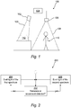
- Fig. 1 schematically illustrates a lighting system 100 in accordance with an aspect of the present inventive concept.
- the system 100 comprises a lighting device 102.
- the lighting device 102 is arranged to emit mixed light comprising a plurality of colors towards an article, as schematically illustrated by light beam 103 emitted towards the article 112 in Fig. 1 .
- the article 112 may be a photograph, a document, a painting, an artwork, fabrics or an artifact.
- the article may be a foodstuff such as a produce, a fruit, a vegetable or a meat article.
- the inventive lighting system is especially advantageous to use for illuminating light sensitive articles, i.e. photosensitive articles, in that it enables an attractive presentation of the article while limiting discoloration of the same.
- an article it is to be understood that a plurality of such articles may be provided within the space illuminated by the lighting device 102.
- the lighting device 102 may comprise a plurality of light sources.
- the lighting device 102 may comprise a plurality of solid-state light sources, such as light emitting diodes (LEDs).
- the LEDs may be organic LEDs or inorganic LEDs.
- Each light source of the lighting device 102 may be arranged to emit light of a different color than the other light sources of the lighting device 102.
- each light source may emit light of a different spectrum, i.e. within a different wavelength interval (which may or may not be partially overlapping), wherein the lighting device 102 is arranged to emit mixed light.
- the lighting device 102 may comprise a red LED, a green LED and a blue LED (an RGB light emitter). According to some embodiments the lighting device 102 may comprise a red LED, a green LED, a blue LED and an amber LED (an RGBA light emitter). The lighting device 102 may further be arranged to allow independent control of the intensity of each light source.
- the system 100 further comprises a controller 104.
- the controller 104 is configured to control the light output of the lighting device 102. More specifically the controller 104 is configured to control the lighting device 102 responsive to detection of presence or movement of an object within a detection zone associated with the article 112, as will be described in detail below.
- the operation of the controller 104 may be implemented using a microprocessor, a microcontroller, a programmable digital signal processor or another programmable device.
- the controller 104 may also, or instead, include an application specific integrated circuit, a programmable gate array or programmable array logic, a programmable device such as the microprocessor, microcontroller or programmable digital signal processor mentioned above; the processor may further include computer executable code that controls operation of the programmable device.
- the controller 104 may provide control signals to the lighting device 102 via a wired or wireless connection.
- the controller 104 may control the spectrum of the emitted light by providing appropriate control signals to the lighting device 102.
- the controller 104 may provide a multi-component control signal to the lighting device 102, each component indicating an intensity level for a respective light source.
- the control signal may indicate an intensity level for each channel, i.e. a red LED, a blue LED, a green LED.
- the control signal may indicate an intensity level for each channel, i.e. a red LED, a blue LED, a green LED, an amber LED.
- the system 100 further comprises a detector 106 defining a detection zone 108.
- the detector 106 is arranged to detect presence of or movement of an object, such as the person 110, within the detection zone 108.
- the detector 106 may sense infrared radiation within the detection zone 108 and detect the object 110 or movement thereof by sensing a changed infrared radiation within the detection zone 108.
- the detector 106 may include a camera capturing images of the detection zone 108 and detect the object 110 or movement thereof within the detection zone 108 by comparing consecutive captured images.
- the detector 106 may include a switch or pressure sensor, arranged at or in the ground such that a person entering the detection zone 108 actuates the switch or pressure sensor, wherein the detector 106 may determine that the person is present or moving within the detection zone 108.
- detectors are detecting radiofrequency signals, such as Bluetooth signals, from a mobile device carried by the person 110 or signals from a handheld scanner which are commonly used in supermarkets.
- the detection may also be sound-based, wherein presence of the person 110 may be detected by detecting a sound (voice, impact sound etc.) from within the detection zone 108 or exceeding a predetermined threshold.
- the detector 106 may provide detection signals to the controller 104 via a wired or wireless connection.
- the detector 106 may for example be arranged to output a first signal to the controller 104 in response to detecting the object 110 or movement of the object 110 within the detection zone 108.
- the detector 106 may further be arranged to output a second signal, which is different from the first signal, to the controller 104 in absence of any object or movement thereof within the detection zone 108.
- the controller 104 is configured to control the lighting device 102 to emit light 103 having a first spectrum towards the article 112 in response to absence of an object or movement of an object within the detection zone 108.
- the controller 104 is further configured to control the lighting device 102 to emit light 103 having a second spectrum towards the article 112 in response to presence of the object 110 or movement of the object 110 within the detection zone 108.
- the light having the first spectrum presents, in at least one wavelength interval, a lower power than the second spectrum in the at least one wavelength interval.
- the light having the first spectrum presents a first spectral power distribution
- the light having the second spectrum presents a second spectral power distribution which is different from the first spectral power distribution.
- the light having the first spectrum may further present in at least a second wavelength interval, a higher power than the second spectrum such that the light having the first spectrum and the light having the second spectrum provide a corresponding level of illumination of the article 112.
- the light having the first spectrum and the light having the second spectrum may provide a corresponding illuminance level (e.g. as measured in lux).
- the light having the first spectrum and the light having the second spectrum may provide a corresponding irradiance level (e.g. as measured in W/m 2 ).
- the illumination level, the illuminance or the irradiance of the light having the first spectrum and the light having the second spectrum may be the same or equal.
- it may suffice that the illumination level, the illuminance or the irradiance of the light having the first spectrum and the light having the second spectrum sufficiently correspond to each other in the sense that switching between the first and second spectrums does not produce a change of the light level which is disturbing or noticeable to a person entering the detection zone 108.
- the first and the second spectrums of the light may further be adapted in accordance with different environments, different applications or for different types of articles.
- the first spectrum is a predetermined first spectrum and the second spectrum is a predetermined second spectrum, wherein the predetermined first and second spectrums are predetermined such that illumination of the article 112 with the light having the predetermined first spectrum results in less discoloration of the article 112 than if the article 112 had been illuminated with the light having the second predetermined spectrum, for a same, i.e. equal, duration.
- wavelengths which are known to accelerate discoloration of the article 112 may be omitted in the first spectrum when no viewer 110 is present in the detection zone 108.
- these wavelengths may be present in the second spectrum when a viewer 110 is present in the detection zone 108.
- wavelengths for which the article 112 is photosensitive may for example be established by subjecting a number of different articles of a same type to light of different wavelengths and identical power and compare the apparent discoloration of the different articles.
- the wavelengths causing the strongest discoloration may be omitted or at least limited in the first spectrum.
- the first spectrum may be arranged or predetermined to present a lower power compared to the second spectrum in an interval of shorter wavelengths (to reduce the risk of discoloration) and a higher power compared to the second spectrum in an interval of longer wavelengths (to maintain a corresponding level of illumination).
- the human eye becomes less sensitive as the wavelength approaches 400 nm.
- configuring the first spectrum to present a reduced or zero power below for example 410, 420 or 430 nm may reduce discoloration of some light sensitive artifacts.
- the first spectrum may be arranged or predetermined to present a lower power, compared to the second spectrum, in one or more wavelength intervals in which the article 112 absorbs light ("absorbing wavelength intervals").
- the first spectrum may be arranged to present a higher power, compared to the second spectrum, in one or more other wavelength intervals, other than the "absorbing wavelength intervals".
- These one or more other wavelength intervals are advantageously wavelength intervals in which the article 112 presents a lower absorption, compared to the "absorbing wavelength intervals".
- illuminating for example a painting including a pigment strongly absorbing light of a particular color, that particular color, and nearby colors may be avoided in the first spectrum to reduce the risk of accelerating discoloration but included in the second spectrum to provide a high quality rendition of the painting.
- first and the second spectrums may be advantageous to impose further requirements, i.e. boundary conditions, on the first and the second spectrums.
- first and second spectrums may be advantageous to arrange the first and second spectrums such that changes between the spectrums are as unnoticeable as possible to people (i.e. objects 110) entering/leaving the detection zone 108 and to people looking in the general direction of the article 112 from outside the detection zone 108.
- the following additional requirements on the spectrums may advantageously be combined with the above mentioned embodiments aiming at limiting discoloration of the article 112.
- the light having the first spectrum and the light having the second spectrum may present a corresponding or substantially equal correlated color temperature.
- a change between light of the first spectrum and light having the second spectrum may be less conspicuous.
- the first and the second spectrums may for example be arranged such that a color temperature of the light having the first spectrum and a color temperature of the light having the second spectrum fall on a same line of constant correlated color temperature in a given chromaticity space.
- the light having the first spectrum and the light having the second spectrum may present a corresponding distance to the black body locus (i.e. the black body line or Planckian locus).
- a distance (which may be zero) to the black body locus of the light having the first spectrum and the light having the second spectrum may be equal, or at least substantially equal.
- a color point of the light having the first spectrum and a color point of the light having the second spectrum may be on the black body locus.
- a distance between a color point of the light to the black body locus may be calculated using an appropriate norm (for example the Euclidean norm) in a given chromaticity space.
- the light having the first spectrum presents a lower color rendering index (CRI) than the light having the second spectrum.
- CRI color rendering index
- lower CRI light may be used when no viewer is within the detection zone 108 wherein the lower spectral content light may limit discoloration of the article 112.
- higher CRI light may be used when a viewer 110 is within the detection zone 108 wherein a greater spectral content may improve the presentation of the article 112.
- Fig. 3 illustrates the result of a test aiming at comparing the discoloration of a sliced liver sausage when illuminated by a conventional white high pressure sodium lamp at 500 Ix (bar A), and when illuminated by light at 500 lx and having a spectrum with a reduced power, compared to the sodium lamp, in the wavelength interval 550 nm to 600 nm (bar B).
- the persons of the test group were shown several samples of sliced meat which had been illuminated with the different light sources for different durations.
- the level of discoloration at which 50% of the test persons considered the discoloration to be unacceptable was taken as a reference point.
- the graph indicates the time taken to reach the unacceptable level of discoloration with the respective spectrum.
- the lighting having a reduced power in the afore-mentioned wavelength interval 550 nm to 600 nm presented approximately a 16% improvement in time over the conventional lighting. Greater improvements may be achieved with even lower power in the wavelength interval 550 nm to 600 nm.
- the lighting system 100 is used for illuminating a meat article.
- the meat may be raw, sliced, unsliced meat or minced.
- the meat may be red meat.
- the controller 104 is configured to control the lighting device 102 to emit light 103 having the first spectrum in response to absence of an object 110 or movement of an object 110 within the detection zone 108.
- the controller 104 is further configured to control the lighting device 102 to emit light 103 having the second spectrum in response to presence of an object 110 or movement of an object 110 within the detection zone 108.
- the first spectrum presents a lower power than the second spectrum within a wavelength interval from 550 nm to 600 nm.
- the light of the first spectrum may present a zero, or negligible, power within this wavelength interval.
- the light of the first spectrum may at least present a reduced power in this wavelength interval, compared to the light of the second spectrum.
- the light of the second spectrum may, or may not, include wavelengths falling within the wavelength interval 550 nm to 600 nm. This may depend on whether or not light of wavelength between 550 to 600 nm contributes to the desired presentation of the meat 112.
- the color temperature of the light of the first spectrum and the second spectrum may be 2200-4000 K. This may result in an attractive presentation of the meat 112 both when viewed from outside and from within the detection zone 108.
- the lighting device 102 may comprise a plurality of differently colored light sources having an independently controllable intensity.
- the lighting device 102 may for example include an RGBA light source.
- the controller 102 may control the lighting device 102 to alter the relative intensities of the RGBA LEDs and thereby vary the spectrum of the emitted light.
- the power of the amber LED may be lower for the light having the first spectrum than the light having the second spectrum.
- a method 200 involving the use of the lighting system 100 for illuminating the article 112 will now be described with reference to Figs 1 and 2 wherein it will be assumed that the lighting device 102 initially emits light 103 having the first spectrum.
- the detector 106 monitors the detection zone 108 (step 202) for detection of an object 110 or movement thereof. If no object or movement is detected within the detection zone 108 the controller 104 controls the lighting device 102 to (continue) emitting light 103 having the first spectrum (step 204). If an object 110 or movement thereof is detected within the detection zone 108 the controller 104 controls the lighting device 102 to change the light output to light 103 having the second spectrum (step 206).
- the controller 104 may be arranged to continue controlling the lighting device 102 to emit light 103 having the second spectrum until the detector 106 determines that the object 110 no longer is present within the detection zone 108, wherein the controller 104 may control the lighting device 102 to return to emitting light 103 having the first spectrum (step 204).
- the detector 106 may be arranged to determine a distance to the object 110 within the detection zone 108.
- the detector 106 may for example include a camera capturing images of the detection zone 108 and determine a position of the object 110 within the detection zone 108 using any appropriate image analysis algorithm known in the art.
- the detector 106 may include three or more detector sub-units arranged to receive a radiofrequency signal (such as a Bluetooth signal) from a mobile device carried by a person, or from a handheld scanner (which are commonly used in supermarkets). The position of the source of the radiofrequency signal within the detection zone may then be calculated from the signals received at the detector sub-units using e.g. triangulation.
- a radiofrequency signal such as a Bluetooth signal
- the determined position may subsequently be translated by the detector 106 to a value indicative of a distance between the detector 106 and the object 110, a distance between the article 112 and the object 110, or a distance between any predetermined position (which may be at or near the article 112) and the object 110.
- the detector 106 may provide a signal indicating the determined distance to the controller 104.
- the detector 106 may be arranged to repeatedly determine a distance to the object 110 and repeatedly provide the determined distance to the controller 104.
- the detector 106 may be arranged to determine a distance to the object 110 and provide the determined distance to the controller 104 in response to a changed distance.
- several objects 110 e.g.
- the detector 106 may provide the distance to the object 110 which is closest to the article 112.
- the controller 104 may, in response to receiving the determined distance from the detector 106, control the lighting device 102 based on the determined distance to provide a gradual transition between the light having the first spectrum and the light having the second spectrum.
- the gradual transition may be stepwise or continuous.
- one or more intermediate spectrums may be defined which are intermediate the predetermined first and the predetermined second spectrum and thereby may provide a stepwise transition between the first and the second spectrum.
- the controller 104 may be arranged to control the lighting device 102 to: emit light of the predetermined first spectrum if the determined distance exceeds a first threshold distance (for example 5 meters, the viewer is distant from the article 112); emit light of a first intermediate spectrum if the determined distance falls between the first and a second threshold distance (for example less than 5 meters but more than 3 meters, the viewer is closer to the article 112); emit light of a second intermediate spectrum if the determined distance falls between the second threshold distance and a third threshold distance (for example less than 3 meters but more than 2 meters, the viewer is even closer to the article 112); and emit light of the predetermined second spectrum if the determined distance falls below the third threshold distance (for example 2 meters, the viewer is able to closely inspect the article 112).
- a first threshold distance for example 5 meters, the viewer is distant from the article 112
- a first intermediate spectrum if the determined distance falls between the first and a second threshold distance (for example less than 5 meters but more than 3 meters, the viewer is closer to the article 112)
- the controller 104 may provide a control signal to the lighting device 102, indicating an intensity level for each light source.
- Each intensity level may be a function of the determined distance.
- the function may for example be a function varying linearly with the determined distance between the maximum and minimum intensities for the light source which, in combination with the minimum and maximum intensities of other light sources, result in the predetermined first and second spectrums.
- the function may be defined to level out (i.e. present a zero derivative) as the determined distance exceeds a predetermined distance (when the person 112 is far away e.g. 5 meters) and falls below another predetermined distance (when the person is close e.g. 1 meter).
- the controller 104 and the detector 106 may be included in the lighting device 102. Two or more of the lighting device 102, the controller 104 and the detector 106 may for example be arranged in a common unit or enclosure.
- the lighting system in accordance with the present inventive concept also presents a more general applicability and may be used for illumination of any article or space wherein illumination with light of different spectrums depending on the presence or movement of a person at the article or in the space may be advantageous.
- a lighting system in accordance with the present inventive concept may be arranged in a shop, a mall, a grocery store, a museum, an art gallery, an exhibition space or other space in which articles may be displayed.
- the lighting system may be provided as a supplement to the existing, conventional lighting (providing ambient or background lighting or similar) in the environment in which the lighting system is arranged.
- a plurality of lighting systems in accordance with the present inventive concept may be arranged to replace all lighting in an environment.
- a plurality of lighting systems, similar to the lighting system 100 may provided for lighting articles in adjacent spaces in an environment. Thereby a continuously lit environment may be provided wherein the articles in each space may be illuminated with light improving the appearance of the articles when a viewer is within the space and illuminated with light limiting discoloration of the articles to a when a viewer is outside the detection zone.
- the lighting system further comprises a controller configured to control the lighting device and a detector defining a detection zone and being configured to determine position data representing a position of an object within the detection zone.
- the controller is further configured to determine an illumination level parameter for the lighting device based on said position data. Thereby an illumination level for the article may be varied depending on the position of the object, which may be a potential viewer of the article.
- the illumination level thereby may be controlled to limit discoloration of the article when no viewer is nearby and optimize the illumination level based on the position of the viewer when the viewer is nearby. By determining the illumination level based on the position it becomes possible to provide a gradually changing illumination level which will minimize distraction for people nearby or within the detection zone.
- the illumination level parameter may indicate an illumination level for the lighting device.
- the controller may further control the lighting device to emit light in accordance with said determined illumination level parameter, wherein the lighting device may emit light at the illumination level indicated by the illumination level parameter.
- the illumination level parameter may for example indicate an output intensity or output power for the lighting device.
- the lighting device may include one or more light emitters wherein the controller may determine an illumination level parameter for each of said light emitters.
- the detector is configured to determine a pair of coordinates representing the position of the object within the detection zone.
- the pair of coordinates may include a first coordinate and a second coordinate.
- the controller may determine the illumination level parameter as a function of the coordinate pair, i.e. as a function of the first coordinate and the second coordinate.
- the pair of coordinates may be Cartesian coordinates. However the pair of coordinates may also be polar coordinates. The origin or the pole may for example be positioned at the article, the lighting device or some other arbitrarily chosen fixed position.
- the first coordinate indicates a position of the object along a first direction or first coordinate axis and the second coordinate indicates a position of the object along a second direction or second coordinate axis.
- the first and the second directions/coordinate axes may be perpendicular.
- the controller is configured to determine the illumination level parameter as a function of the position data.
- the function may be arranged to provide an illumination level parameter which, for a first range of values of the first coordinate, monotonically increases as a function of the first coordinate and, for a second range of values of the first coordinate, monotonically decreases as a function of the first coordinate. More specifically, the function may further be arranged to, for a fixed value of the second coordinate, provide an illumination level parameter which, for the first range of values of the first coordinate, monotonically increases as a function of the first coordinate and, for the second range of values of the first coordinate, monotonically decreases as a function of the first coordinate.
- the function may further be arranged to provide an illumination level parameter which, for a third range of values of the second coordinate, monotonically increases or decreases as a function of the second coordinate.
- the illumination level provided by the light source may thereby be varied depending on the position of the object, e.g. the viewer, within the detection zone.
- the coordinate system may for example be defined such that the origin coincides with the article to be illuminated wherein the first coordinate indicates a distance between the object and the article along the first direction or first coordinate axis and the second coordinate indicates a distance between the object and the article along the second direction or second coordinate axis.
- the second direction or second coordinate axis may correspond to a direction from which potential viewers of the article generally approaches the article.
- the first direction or first coordinate axis may correspond to a direction which is perpendicular to the second direction.
- the second direction may be perpendicular to the horizontal extension of the wall and the first direction may extend along the wall.
- the first direction may extend along the length of the counter and the second direction may extend in a direction perpendicular to the first direction, and thus away from the counter.
- the above mentioned third range of values of the second coordinate may for example represent a range of distances from the wall or the counter (e.g. closer than 8 meters, between 5-2 meters etc).
- the above mentioned first range of values of the first coordinate may for example represent a range of distances from the second coordinate axis on a first side thereof and the above mentioned second range of values of the first coordinate may for example represent a range of distances from the second coordinate axis on a second side thereof which is opposite said first side (e.g. +/- 2 meters).
- the function may further be arranged to provide an illumination level parameter which, for a fourth range of values of the first coordinate and a fifth range of values of the second coordinate, is constant.
- the zone may for example be defined to extend from 0 meters to 2 meters from the wall or counter and within 1 meter from the painting along the wall or from a predetermined position along the counter. It should be understood that the numerical examples above merely are provided to facilitate understanding and not should be construed as limiting.
- the lighting device is arranged to illuminate a region with an illumination pattern
- the controller is configured to control the illumination pattern provided by the lighting device based on the position of the object within the detection zone.
- the controller may be arranged to control a position of maximum illumination level within the illuminated region and a magnitude of the maximum illumination level based on the position of the object within the detection zone.
- the controller may in particular be arranged to control a position of maximum illumination level within the illuminated region based on the first coordinate and a magnitude of the maximum illumination level based on the second coordinate.
- an adaptable and variable illumination pattern may be provided to illuminate articles distributed within the illuminated region, for example in a display or a in counter.
- the illumination of the articles may be different depending on their location within the illumination pattern and depending on the position of the object, e.g. the viewer.
- the lighting device is arranged to illuminate an elongate region extending along a first direction.
- the detector is configured to determine a first coordinate and a second coordinate representing the position of the object within the detection zone, wherein the first coordinate represents a coordinate of the object along the first direction and the second coordinate represents a coordinate of the object in a second direction perpendicular to the first direction.
- the controller is configured to control an illumination pattern provided by the lighting device in the elongate region based on the first and the second coordinate, wherein, for a determined position of the object, an illumination level of the illumination pattern is varied along the first direction and wherein a maximum illumination level of the illumination pattern is based on the second coordinate.
- an adaptable and variable illumination pattern may be provided to illuminate articles in an elongate region, for example an elongate display or counter.
- the second coordinate may represent a distance between the object and the elongate region, the distance being projected on the (horizontally extending) normal to the first direction.
- the controller may be configured to determine the position of the maximum illumination level of the illumination pattern along the first direction based on the first coordinate. Especially the position of the maximum illumination level, along the first direction, may correspond to or coincide with the first coordinate.
- the elongate region may include a plurality of articles distributed along the first direction, which articles are to be illuminated.
- the lighting system (not shown in Fig. 4 ) includes a lighting device arranged to illuminate an elongate region at a display 400.
- the display 400 may in one example be a display for foodstuff, such as fresh produce or bread.
- the display 400 may be a display for meat such as a meat counter or similar in a grocery store or a delicatessen).
- the display 400 may more generally be a display for one or more light sensitive articles of any of the types mentioned earlier in the description.
- the display 400 and the elongate region extend in what will be referred to as a first direction.
- the lighting device may for example include a plurality of light emitters, such as LEDs arranged in an elongated array and being arranged to emit light which together illuminate the elongated region.
- the number and the density of the light emitters may be varied in accordance with the application. An increased density may provide a more precisely controllable illumination pattern.
- the lighting device may be arranged in the display 400, for example below a ceiling of the display 400.
- Each of the light emitters may present an individually controllable level of illumination or intensity, i.e. be individually dimmable.
- the lighting system further comprises a controller configured to control the lighting device and the light emitters thereof.
- the controller may be embodied in a manner analogous to the controller 104 in Fig. 1 (i.e. include an application specific integrated circuit, a programmable gate array, a programmable device such as a microprocessor etc.).
- the controller is configured to control the illumination level of each light emitter and thereby control an illumination pattern provided by the light source.
- the system further comprises a detector defining a detection zone 402 and being configured to determine position data representing a position of an object within the detection zone 402.
- the detection zone 402 may be arranged to extend in front of the display 400, and advantageously cover a region which people enter for the purpose of viewing articles in the display 400.
- the detector may in analogy with the detector 106 be embodied as an image capturing unit capturing images of the detection zone and capable of determining a position of an object, e.g. a customer, schematically indicated by element 406 in Fig. 4 , present or moving about within the detection zone 402.
- the detector may determine position data for the object which position data includes a pair of coordinates (wc, dc) representing the position of the object 406 within the detection zone 402 with respect to a coordinate system w-d, wherein the w-axis is parallel to the above-mentioned first direction and the d-axis is perpendicular to the w-axis.
- the origin of the coordinate system may for example be positioned at the article, the lighting device or some other arbitrarily chosen fixed position.
- the coordinates (wc, dc) may represent a position of the object 406 in relation to the display 400.
- the detector may provide the position data (wc, dc) to the controller using a wired or wireless connection.
- the controller may determine a plurality of illumination level parameters for controlling the illumination level of the light emitters of the lighting device.
- the maximum illumination level I max of the illumination pattern for a given position (wc, dc) of the object 406 may be determined based on the coordinate dc.
- the maximum illumination level I max may be gradually changed as a function of dc.
- the maximum illumination level I max may be continuously decreased as a function of increasing dc.
- Fig. 5 illustrates the maximum illumination level I max of the illumination pattern as a function of the coordinate dc.
- the maximum illumination level I max may for example correspond to a maximum illumination level which the light source may provide at a given position in the elongated region.
- the maximum illumination level I max may correspond to a maximum illumination level which the light source may provide at a coordinate along the w-axis.
- an illumination level provided by the illumination pattern may be varied along the first direction.
- the illumination level may gradually increase along the first direction to a position in the illumination pattern corresponding to the coordinate wc, and thereafter gradually decrease.
- the illumination pattern may reach the maximum illumination level I max (determined e.g. in accordance with the example in Fig. 5 ).
- the maximum illumination level I max may be provided at the coordinate wc along the w-axis.
- the illumination pattern may be present a region of a constant illumination level within a range wf centered at the coordinate wc.
- the illumination level may be varied between a maximum illumination level which the light source may provide at a given position (i.e. corresponding to an illumination level of 100 %) and a predetermined minimum illumination level (e.g. 50 % of the maximum illumination level).
- a predetermined minimum illumination level e.g. 50 % of the maximum illumination level.
- the transitions may be determined in accordance with any monotonically decreasing/increasing function. The functions may not even be continuously decreasing/increasing but also gradual and stepwise changes are contemplated.
- the detector may further define a second detection zone 404. If the position of the object 406 falls within the second detection zone 406 the controller may be configured to control the light source to provide an illumination pattern providing a constant illumination level within the display 400 along the first direction. The controller may further control the plurality of light emitters of the light source to emit light at their respective maximum intensity. According to a further option, if more than one object 406 is present in the detection zone 402, the illumination level may be constant within the illumination pattern along the first direction. The illumination level I max may for example be determined based on the coordinate dc of the object which is closest to the display 200.
Landscapes
- Life Sciences & Earth Sciences (AREA)
- Engineering & Computer Science (AREA)
- Wood Science & Technology (AREA)
- Zoology (AREA)
- Chemical & Material Sciences (AREA)
- Food Science & Technology (AREA)
- Polymers & Plastics (AREA)
- Circuit Arrangement For Electric Light Sources In General (AREA)
Claims (15)
- Système d'éclairage (100) pour illuminer un article (112) comprenant :un dispositif d'éclairage (102) agencé pour émettre de la lumière (103) vers l'article (112), dans lequel un spectre de la lumière émise peut être commandé,une unité de commande (104) configurée pour commander le dispositif d'éclairage (102) en réponse à une détection de présence ou de mouvement d'un objet (110) à l'intérieur d'une zone de détection (108) associée à l'article (112), l'unité de commande (104) étant configurée pour :commander le dispositif d'éclairage (102) pour émettre de la lumière (103) ayant un premier spectre en cas d'absence de l'objet (110) ou en cas d'absence de mouvement de l'objet à l'intérieur de la zone de détection (108), etcommander le dispositif d'éclairage (102) pour émettre de la lumière (103) ayant un second spectre en réponse à la présence de l'objet (110) ou du mouvement de l'objet (110) à l'intérieur de la zone de détection (108),caractérisé par
dans lequel la lumière ayant le premier spectre présente, dans au moins un intervalle de longueurs d'onde, une puissance inférieure à la lumière ayant le second spectre, et dans lequel la lumière ayant le premier spectre et la lumière ayant le second spectre fournissant le même niveau d'éclairage dudit article (112), de sorte que commuter entre les premier et second spectres ne produit pas de changement du niveau de lumière qui soit dérangeant ou perceptible à une personne pénétrant dans la zone de détection. - Système d'éclairage (100) selon la revendication 1, dans lequel la lumière (103) ayant le premier spectre et la lumière (103) ayant le second spectre présentent une température de couleurs corrélée correspondante.
- Système d'éclairage (100) selon l'une quelconque des revendications 1 à 2, dans lequel la lumière (103) ayant le premier spectre et la lumière (103) ayant le second spectre présentent une distance correspondante au lieu géométrique de corps noir.
- Système d'éclairage (100) selon l'une quelconque des revendications 1 à 3, dans lequel la lumière (103) ayant le premier spectre présente un indice de rendu de couleurs inférieur à la lumière (103) ayant le second spectre.
- Système d'éclairage (100) selon l'une quelconque des revendications 1 à 4, dans lequel ledit premier spectre est un premier spectre prédéterminé et ledit second spectre est un second spectre prédéterminé, dans lequel lesdits premier et second spectres prédéterminés sont prédéterminés de sorte que l'illumination de l'article (112) avec la lumière (103) ayant le premier spectre prédéterminé aboutit à moins de décoloration de l'article (112) que si ledit article avait été illuminé avec la lumière (103) ayant le second spectre prédéterminé, pendant une même durée.
- Système d'éclairage (100) selon l'une quelconque des revendications 1 à 5, dans lequel ledit premier spectre est un premier spectre prédéterminé et ledit second spectre est un second spectre prédéterminé, dans lequel lesdits premier et second spectres prédéterminés sont prédéterminés de sorte que la lumière ayant ledit premier spectre prédéterminé présente, dans l'au moins un intervalle de longueurs d'onde dans lequel ledit article (112) absorbe la lumière, une puissance inférieure au second spectre.
- Système d'éclairage (100) selon l'une quelconque des revendications 1 à 6, dans lequel le premier spectre présente une puissance inférieure au second spectre à l'intérieur d'un intervalle de longueurs d'onde allant de 550 nm à 600 nm.
- Système d'éclairage (100) selon l'une quelconque des revendications 1 à 7, dans lequel le dispositif d'éclairage (102) comprend une pluralité de sources de lumière, chaque source de lumière étant agencée pour émettre une lumière (103) d'une couleur différente des autres sources de lumière, et l'intensité de chaque source de lumière pouvant être indépendamment commandée par l'unité de commande (104), dans lequel le dispositif d'éclairage (102) est agencé pour émettre une lumière mélangée (103).
- Système d'éclairage (100) selon la revendication 8, dans lequel le dispositif d'éclairage (102) comprend au moins quatre sources de lumière.
- Système d'éclairage (100) selon l'une quelconque des revendications 1 à 9, dans lequel le dispositif d'éclairage (102) comprend une source de lumière rouge, une source de lumière verte, une source de lumière bleue et une source de lumière ambre.
- Système d'éclairage (100) selon la revendication 10, dans lequel une puissance de sortie de la source de lumière ambre est inférieure pour la lumière ayant le premier spectre en comparaison à une puissance de sortie de la source de lumière ambre pour la lumière ayant le second spectre.
- Système d'éclairage (100) selon l'une quelconque des revendications 1 à 11, comprenant en outre un détecteur (106) pour définir une zone de détection (108) associée à l'article (112) et étant agencé pour détecter la présence ou le mouvement de l'objet (110) à l'intérieur de la zone de détection (108).
- Système d'éclairage (100) selon la revendication 12, dans lequel le détecteur (106) est agencé pour déterminer une distance jusqu'à l'objet détecté (110), et dans lequel l'unité de commande (104) est agencée pour commander le dispositif d'éclairage (102) sur la base de la distance déterminée pour fournir une transition graduelle entre la lumière (103) ayant le premier spectre et la lumière (103) ayant le second spectre.
- Utilisation d'un système d'éclairage (100) selon l'une quelconque des revendications 1 à 13 pour illuminer un article de viande.
- Utilisation d'un système d'éclairage (100) selon l'une quelconque des revendications 1 à 13 pour illuminer un article sensible à la lumière, comme une photographie, un document, une peinture, une illustration, des tissus, un artefact ou autre article photosensible.
Applications Claiming Priority (2)
| Application Number | Priority Date | Filing Date | Title |
|---|---|---|---|
| EP14160191 | 2014-03-17 | ||
| PCT/EP2015/055491 WO2015140131A1 (fr) | 2014-03-17 | 2015-03-17 | Système d'éclairage destiné à éclairer un article |
Publications (2)
| Publication Number | Publication Date |
|---|---|
| EP3120671A1 EP3120671A1 (fr) | 2017-01-25 |
| EP3120671B1 true EP3120671B1 (fr) | 2018-09-12 |
Family
ID=50287948
Family Applications (1)
| Application Number | Title | Priority Date | Filing Date |
|---|---|---|---|
| EP15709960.7A Active EP3120671B1 (fr) | 2014-03-17 | 2015-03-17 | Système d'éclairage permettant d'éclairer un article |
Country Status (6)
| Country | Link |
|---|---|
| US (1) | US10039170B2 (fr) |
| EP (1) | EP3120671B1 (fr) |
| JP (1) | JP6617113B2 (fr) |
| CN (1) | CN106538063B (fr) |
| RU (1) | RU2016140485A (fr) |
| WO (1) | WO2015140131A1 (fr) |
Families Citing this family (9)
| Publication number | Priority date | Publication date | Assignee | Title |
|---|---|---|---|---|
| US9851072B2 (en) | 2013-04-09 | 2017-12-26 | Philips Lighting Holding B.V. | Arrangement for changing the visual appearance of a target object |
| DE102015215234A1 (de) * | 2015-08-10 | 2017-02-16 | Fraunhofer-Gesellschaft zur Förderung der angewandten Forschung e.V. | Einrichtung zum Absichern eines Sicherheitsbereichs um mindestens eine automatisch arbeitende Maschine |
| CN109892011B (zh) | 2016-11-01 | 2022-02-01 | 昕诺飞控股有限公司 | 照明系统和照明系统控制方法 |
| CN112188832B (zh) * | 2018-05-31 | 2023-08-29 | 昕诺飞控股有限公司 | 用于维持室内植物生长的园艺光照设备、系统和方法 |
| DE102018121898A1 (de) * | 2018-09-07 | 2020-03-12 | Siteco Beleuchtungstechnik Gmbh | Sportstättenbeleuchtung zur Förderung des Rasenwachstums |
| CN109566382A (zh) * | 2018-12-05 | 2019-04-05 | 深圳凌晨之光科技有限公司 | 具有光照装置的种植设备 |
| US11236893B2 (en) * | 2020-04-06 | 2022-02-01 | Robert Bosch Gmbh | Work light having jobsite security features |
| CN114245525A (zh) * | 2021-11-16 | 2022-03-25 | 深圳市合信达控制系统有限公司 | 一种带夜灯的温控器 |
| US20240112433A1 (en) * | 2022-09-29 | 2024-04-04 | Zebra Technologies Corporation | End User Selectable/Variable Object Detect Illumination |
Family Cites Families (22)
| Publication number | Priority date | Publication date | Assignee | Title |
|---|---|---|---|---|
| JPS63228595A (ja) * | 1987-03-18 | 1988-09-22 | 東芝ライテック株式会社 | 照明装置 |
| FR2624712A1 (fr) | 1987-12-16 | 1989-06-23 | Theis Gerard | Presentoir tournant a programmation |
| JPH0794146A (ja) * | 1993-09-24 | 1995-04-07 | Matsushita Electric Ind Co Ltd | 照明ランプ、照明器具およびそれらを備えた照明装置ならびに照明環境システム |
| DE19636963B4 (de) | 1996-06-11 | 2006-05-11 | Steinel Gmbh & Co Kg | Steuervorrichtung |
| JP3932581B2 (ja) * | 1996-11-08 | 2007-06-20 | 松下電工株式会社 | 照明装置 |
| US7014336B1 (en) * | 1999-11-18 | 2006-03-21 | Color Kinetics Incorporated | Systems and methods for generating and modulating illumination conditions |
| US6275163B1 (en) * | 1998-08-24 | 2001-08-14 | Leviton Manufacturing Co., Inc. | Automatic switch dimmer device |
| US7023543B2 (en) * | 2002-08-01 | 2006-04-04 | Cunningham David W | Method for controlling the luminous flux spectrum of a lighting fixture |
| US7598859B2 (en) | 2004-08-13 | 2009-10-06 | Osram Sylvania Inc. | Method and system for controlling lighting |
| US7729941B2 (en) | 2006-11-17 | 2010-06-01 | Integrated Illumination Systems, Inc. | Apparatus and method of using lighting systems to enhance brand recognition |
| JP5398702B2 (ja) | 2007-05-10 | 2014-01-29 | コーニンクレッカ フィリップス エヌ ヴェ | 衣類架のためのインタラクティブ照明システム |
| JP2009028491A (ja) * | 2007-06-22 | 2009-02-12 | Panasonic Electric Works Co Ltd | 棚照明システム及び棚ユニット照明システム |
| GB0807197D0 (en) * | 2008-04-19 | 2008-05-28 | Rylatt Paul | Illumination adjustment device |
| WO2010058370A2 (fr) | 2008-11-21 | 2010-05-27 | Philips Intellectual Property & Standards Gmbh | Système et procédé de commande induite par produit de scènes lumineuses |
| CN102422718B (zh) | 2009-05-14 | 2014-12-24 | 皇家飞利浦电子股份有限公司 | 照明装置 |
| WO2011070473A1 (fr) | 2009-12-09 | 2011-06-16 | Koninklijke Philips Electronics N.V. | Système lumineux destiné à mettre en valeur des objets |
| CN102740740A (zh) * | 2010-01-28 | 2012-10-17 | 皇家飞利浦电子股份有限公司 | 用于强调物体颜色的方法和系统 |
| KR20110133819A (ko) | 2010-06-07 | 2011-12-14 | 삼성엘이디 주식회사 | 상품 전시 조명 제어 시스템 |
| WO2013011409A1 (fr) * | 2011-07-19 | 2013-01-24 | Koninklijke Philips Electronics N.V. | Dispositif d'eclairage ressemblant a une lampe a incandescence |
| JP2013084544A (ja) * | 2011-09-26 | 2013-05-09 | Toshiba Lighting & Technology Corp | 照明装置、照明器具および照明制御システム |
| US8698980B2 (en) * | 2011-11-14 | 2014-04-15 | Planck Co., Ltd. | Color regulating device for illumination and apparatus using the same, and method of regulating color |
| JP6339088B2 (ja) * | 2012-10-26 | 2018-06-06 | フィリップス ライティング ホールディング ビー ヴィ | 互いに近くに位置するユーザに個別照明を与える照明方法 |
-
2015
- 2015-03-17 EP EP15709960.7A patent/EP3120671B1/fr active Active
- 2015-03-17 WO PCT/EP2015/055491 patent/WO2015140131A1/fr active Application Filing
- 2015-03-17 RU RU2016140485A patent/RU2016140485A/ru not_active Application Discontinuation
- 2015-03-17 JP JP2016557639A patent/JP6617113B2/ja active Active
- 2015-03-17 CN CN201580025538.0A patent/CN106538063B/zh active Active
- 2015-03-17 US US15/127,326 patent/US10039170B2/en active Active
Non-Patent Citations (1)
| Title |
|---|
| None * |
Also Published As
| Publication number | Publication date |
|---|---|
| EP3120671A1 (fr) | 2017-01-25 |
| WO2015140131A1 (fr) | 2015-09-24 |
| CN106538063A (zh) | 2017-03-22 |
| US10039170B2 (en) | 2018-07-31 |
| JP6617113B2 (ja) | 2019-12-04 |
| CN106538063B (zh) | 2019-11-01 |
| RU2016140485A (ru) | 2018-04-17 |
| JP2017513186A (ja) | 2017-05-25 |
| US20170150571A1 (en) | 2017-05-25 |
Similar Documents
| Publication | Publication Date | Title |
|---|---|---|
| EP3120671B1 (fr) | Système d'éclairage permettant d'éclairer un article | |
| US9185778B2 (en) | Dynamic lighting arrangement for product presentation | |
| US9635730B2 (en) | Color emphasis and preservation of objects using reflection spectra | |
| US9392651B2 (en) | Lighting methods and apparatus with selectively applied face lighting component | |
| US9907144B2 (en) | Illumination system | |
| CN106973471B (zh) | 照明系统和照明方法 | |
| US10056018B1 (en) | Dynamic color rendering methods and systems providing just-noticeable color accentuation and quasi-animation effects | |
| JP2009028491A (ja) | 棚照明システム及び棚ユニット照明システム | |
| US20170006686A1 (en) | Method for controlling an adaptive illumination device, and an illumination system for carrying out said method | |
| US11747004B2 (en) | Apparatus for providing semantic information and a method of operating the same | |
| KR101450405B1 (ko) | 식품 매장 조명 시스템 | |
| WO2015010974A1 (fr) | Dispositif d'éclairage pour réglage de couleur de lumière séparément dans plusieurs zones | |
| KR101263708B1 (ko) | 지능형 전시 조명 시스템 | |
| JP2016048605A (ja) | 照明制御装置、及び、照明方法 |
Legal Events
| Date | Code | Title | Description |
|---|---|---|---|
| STAA | Information on the status of an ep patent application or granted ep patent |
Free format text: STATUS: THE INTERNATIONAL PUBLICATION HAS BEEN MADE |
|
| PUAI | Public reference made under article 153(3) epc to a published international application that has entered the european phase |
Free format text: ORIGINAL CODE: 0009012 |
|
| STAA | Information on the status of an ep patent application or granted ep patent |
Free format text: STATUS: REQUEST FOR EXAMINATION WAS MADE |
|
| 17P | Request for examination filed |
Effective date: 20161017 |
|
| AK | Designated contracting states |
Kind code of ref document: A1 Designated state(s): AL AT BE BG CH CY CZ DE DK EE ES FI FR GB GR HR HU IE IS IT LI LT LU LV MC MK MT NL NO PL PT RO RS SE SI SK SM TR |
|
| AX | Request for extension of the european patent |
Extension state: BA ME |
|
| STAA | Information on the status of an ep patent application or granted ep patent |
Free format text: STATUS: EXAMINATION IS IN PROGRESS |
|
| 17Q | First examination report despatched |
Effective date: 20170502 |
|
| DAV | Request for validation of the european patent (deleted) | ||
| DAX | Request for extension of the european patent (deleted) | ||
| RIN1 | Information on inventor provided before grant (corrected) |
Inventor name: POORT, SIMONE HELENA MARIA Inventor name: SCHOBBEN, DANIEL WILLEM ELISABETH Inventor name: BOUWKAMP-WIJNOLTZ, ANNA LOUISE Inventor name: BAAIJENS, JOHANNES PETRUS WILHELMUS |
|
| GRAP | Despatch of communication of intention to grant a patent |
Free format text: ORIGINAL CODE: EPIDOSNIGR1 |
|
| STAA | Information on the status of an ep patent application or granted ep patent |
Free format text: STATUS: GRANT OF PATENT IS INTENDED |
|
| INTG | Intention to grant announced |
Effective date: 20180329 |
|
| RIN1 | Information on inventor provided before grant (corrected) |
Inventor name: POORT, SIMONE HELENA MARIA Inventor name: SCHOBBEN, DANIEL WILLEM ELISABETH Inventor name: BOUWKAMP-WIJNOLTZ, ANNA LOUISE Inventor name: BAAIJENS, JOHANNES PETRUS WILHELMUS |
|
| GRAS | Grant fee paid |
Free format text: ORIGINAL CODE: EPIDOSNIGR3 |
|
| GRAA | (expected) grant |
Free format text: ORIGINAL CODE: 0009210 |
|
| STAA | Information on the status of an ep patent application or granted ep patent |
Free format text: STATUS: THE PATENT HAS BEEN GRANTED |
|
| AK | Designated contracting states |
Kind code of ref document: B1 Designated state(s): AL AT BE BG CH CY CZ DE DK EE ES FI FR GB GR HR HU IE IS IT LI LT LU LV MC MK MT NL NO PL PT RO RS SE SI SK SM TR |
|
| REG | Reference to a national code |
Ref country code: GB Ref legal event code: FG4D |
|
| REG | Reference to a national code |
Ref country code: CH Ref legal event code: EP |
|
| REG | Reference to a national code |
Ref country code: IE Ref legal event code: FG4D |
|
| REG | Reference to a national code |
Ref country code: DE Ref legal event code: R096 Ref document number: 602015016061 Country of ref document: DE |
|
| REG | Reference to a national code |
Ref country code: AT Ref legal event code: REF Ref document number: 1042153 Country of ref document: AT Kind code of ref document: T Effective date: 20181015 |
|
| RAP2 | Party data changed (patent owner data changed or rights of a patent transferred) |
Owner name: PHILIPS LIGHTING HOLDING B.V. |
|
| REG | Reference to a national code |
Ref country code: NL Ref legal event code: MP Effective date: 20180912 |
|
| REG | Reference to a national code |
Ref country code: LT Ref legal event code: MG4D |
|
| PG25 | Lapsed in a contracting state [announced via postgrant information from national office to epo] |
Ref country code: GR Free format text: LAPSE BECAUSE OF FAILURE TO SUBMIT A TRANSLATION OF THE DESCRIPTION OR TO PAY THE FEE WITHIN THE PRESCRIBED TIME-LIMIT Effective date: 20181213 Ref country code: NO Free format text: LAPSE BECAUSE OF FAILURE TO SUBMIT A TRANSLATION OF THE DESCRIPTION OR TO PAY THE FEE WITHIN THE PRESCRIBED TIME-LIMIT Effective date: 20181212 Ref country code: BG Free format text: LAPSE BECAUSE OF FAILURE TO SUBMIT A TRANSLATION OF THE DESCRIPTION OR TO PAY THE FEE WITHIN THE PRESCRIBED TIME-LIMIT Effective date: 20181212 Ref country code: SE Free format text: LAPSE BECAUSE OF FAILURE TO SUBMIT A TRANSLATION OF THE DESCRIPTION OR TO PAY THE FEE WITHIN THE PRESCRIBED TIME-LIMIT Effective date: 20180912 Ref country code: RS Free format text: LAPSE BECAUSE OF FAILURE TO SUBMIT A TRANSLATION OF THE DESCRIPTION OR TO PAY THE FEE WITHIN THE PRESCRIBED TIME-LIMIT Effective date: 20180912 Ref country code: FI Free format text: LAPSE BECAUSE OF FAILURE TO SUBMIT A TRANSLATION OF THE DESCRIPTION OR TO PAY THE FEE WITHIN THE PRESCRIBED TIME-LIMIT Effective date: 20180912 Ref country code: LT Free format text: LAPSE BECAUSE OF FAILURE TO SUBMIT A TRANSLATION OF THE DESCRIPTION OR TO PAY THE FEE WITHIN THE PRESCRIBED TIME-LIMIT Effective date: 20180912 |
|
| PG25 | Lapsed in a contracting state [announced via postgrant information from national office to epo] |
Ref country code: LV Free format text: LAPSE BECAUSE OF FAILURE TO SUBMIT A TRANSLATION OF THE DESCRIPTION OR TO PAY THE FEE WITHIN THE PRESCRIBED TIME-LIMIT Effective date: 20180912 Ref country code: HR Free format text: LAPSE BECAUSE OF FAILURE TO SUBMIT A TRANSLATION OF THE DESCRIPTION OR TO PAY THE FEE WITHIN THE PRESCRIBED TIME-LIMIT Effective date: 20180912 Ref country code: AL Free format text: LAPSE BECAUSE OF FAILURE TO SUBMIT A TRANSLATION OF THE DESCRIPTION OR TO PAY THE FEE WITHIN THE PRESCRIBED TIME-LIMIT Effective date: 20180912 |
|
| RAP2 | Party data changed (patent owner data changed or rights of a patent transferred) |
Owner name: SIGNIFY HOLDING B.V. |
|
| REG | Reference to a national code |
Ref country code: AT Ref legal event code: MK05 Ref document number: 1042153 Country of ref document: AT Kind code of ref document: T Effective date: 20180912 |
|
| PG25 | Lapsed in a contracting state [announced via postgrant information from national office to epo] |
Ref country code: RO Free format text: LAPSE BECAUSE OF FAILURE TO SUBMIT A TRANSLATION OF THE DESCRIPTION OR TO PAY THE FEE WITHIN THE PRESCRIBED TIME-LIMIT Effective date: 20180912 Ref country code: PL Free format text: LAPSE BECAUSE OF FAILURE TO SUBMIT A TRANSLATION OF THE DESCRIPTION OR TO PAY THE FEE WITHIN THE PRESCRIBED TIME-LIMIT Effective date: 20180912 Ref country code: IS Free format text: LAPSE BECAUSE OF FAILURE TO SUBMIT A TRANSLATION OF THE DESCRIPTION OR TO PAY THE FEE WITHIN THE PRESCRIBED TIME-LIMIT Effective date: 20190112 Ref country code: ES Free format text: LAPSE BECAUSE OF FAILURE TO SUBMIT A TRANSLATION OF THE DESCRIPTION OR TO PAY THE FEE WITHIN THE PRESCRIBED TIME-LIMIT Effective date: 20180912 Ref country code: CZ Free format text: LAPSE BECAUSE OF FAILURE TO SUBMIT A TRANSLATION OF THE DESCRIPTION OR TO PAY THE FEE WITHIN THE PRESCRIBED TIME-LIMIT Effective date: 20180912 Ref country code: NL Free format text: LAPSE BECAUSE OF FAILURE TO SUBMIT A TRANSLATION OF THE DESCRIPTION OR TO PAY THE FEE WITHIN THE PRESCRIBED TIME-LIMIT Effective date: 20180912 Ref country code: AT Free format text: LAPSE BECAUSE OF FAILURE TO SUBMIT A TRANSLATION OF THE DESCRIPTION OR TO PAY THE FEE WITHIN THE PRESCRIBED TIME-LIMIT Effective date: 20180912 Ref country code: EE Free format text: LAPSE BECAUSE OF FAILURE TO SUBMIT A TRANSLATION OF THE DESCRIPTION OR TO PAY THE FEE WITHIN THE PRESCRIBED TIME-LIMIT Effective date: 20180912 Ref country code: IT Free format text: LAPSE BECAUSE OF FAILURE TO SUBMIT A TRANSLATION OF THE DESCRIPTION OR TO PAY THE FEE WITHIN THE PRESCRIBED TIME-LIMIT Effective date: 20180912 |
|
| PG25 | Lapsed in a contracting state [announced via postgrant information from national office to epo] |
Ref country code: SK Free format text: LAPSE BECAUSE OF FAILURE TO SUBMIT A TRANSLATION OF THE DESCRIPTION OR TO PAY THE FEE WITHIN THE PRESCRIBED TIME-LIMIT Effective date: 20180912 Ref country code: SM Free format text: LAPSE BECAUSE OF FAILURE TO SUBMIT A TRANSLATION OF THE DESCRIPTION OR TO PAY THE FEE WITHIN THE PRESCRIBED TIME-LIMIT Effective date: 20180912 Ref country code: PT Free format text: LAPSE BECAUSE OF FAILURE TO SUBMIT A TRANSLATION OF THE DESCRIPTION OR TO PAY THE FEE WITHIN THE PRESCRIBED TIME-LIMIT Effective date: 20190112 |
|
| REG | Reference to a national code |
Ref country code: DE Ref legal event code: R097 Ref document number: 602015016061 Country of ref document: DE |
|
| PLBE | No opposition filed within time limit |
Free format text: ORIGINAL CODE: 0009261 |
|
| STAA | Information on the status of an ep patent application or granted ep patent |
Free format text: STATUS: NO OPPOSITION FILED WITHIN TIME LIMIT |
|
| PG25 | Lapsed in a contracting state [announced via postgrant information from national office to epo] |
Ref country code: DK Free format text: LAPSE BECAUSE OF FAILURE TO SUBMIT A TRANSLATION OF THE DESCRIPTION OR TO PAY THE FEE WITHIN THE PRESCRIBED TIME-LIMIT Effective date: 20180912 |
|
| 26N | No opposition filed |
Effective date: 20190613 |
|
| PG25 | Lapsed in a contracting state [announced via postgrant information from national office to epo] |
Ref country code: SI Free format text: LAPSE BECAUSE OF FAILURE TO SUBMIT A TRANSLATION OF THE DESCRIPTION OR TO PAY THE FEE WITHIN THE PRESCRIBED TIME-LIMIT Effective date: 20180912 |
|
| PG25 | Lapsed in a contracting state [announced via postgrant information from national office to epo] |
Ref country code: MC Free format text: LAPSE BECAUSE OF FAILURE TO SUBMIT A TRANSLATION OF THE DESCRIPTION OR TO PAY THE FEE WITHIN THE PRESCRIBED TIME-LIMIT Effective date: 20180912 |
|
| REG | Reference to a national code |
Ref country code: CH Ref legal event code: PL |
|
| PG25 | Lapsed in a contracting state [announced via postgrant information from national office to epo] |
Ref country code: LU Free format text: LAPSE BECAUSE OF NON-PAYMENT OF DUE FEES Effective date: 20190317 |
|
| REG | Reference to a national code |
Ref country code: BE Ref legal event code: MM Effective date: 20190331 |
|
| PG25 | Lapsed in a contracting state [announced via postgrant information from national office to epo] |
Ref country code: IE Free format text: LAPSE BECAUSE OF NON-PAYMENT OF DUE FEES Effective date: 20190317 Ref country code: LI Free format text: LAPSE BECAUSE OF NON-PAYMENT OF DUE FEES Effective date: 20190331 Ref country code: CH Free format text: LAPSE BECAUSE OF NON-PAYMENT OF DUE FEES Effective date: 20190331 |
|
| PG25 | Lapsed in a contracting state [announced via postgrant information from national office to epo] |
Ref country code: BE Free format text: LAPSE BECAUSE OF NON-PAYMENT OF DUE FEES Effective date: 20190331 |
|
| PG25 | Lapsed in a contracting state [announced via postgrant information from national office to epo] |
Ref country code: TR Free format text: LAPSE BECAUSE OF FAILURE TO SUBMIT A TRANSLATION OF THE DESCRIPTION OR TO PAY THE FEE WITHIN THE PRESCRIBED TIME-LIMIT Effective date: 20180912 |
|
| PG25 | Lapsed in a contracting state [announced via postgrant information from national office to epo] |
Ref country code: MT Free format text: LAPSE BECAUSE OF NON-PAYMENT OF DUE FEES Effective date: 20190317 |
|
| REG | Reference to a national code |
Ref country code: DE Ref legal event code: R081 Ref document number: 602015016061 Country of ref document: DE Owner name: SIGNIFY HOLDING B.V., NL Free format text: FORMER OWNER: PHILIPS LIGHTING HOLDING B.V., EINDHOVEN, NL |
|
| PG25 | Lapsed in a contracting state [announced via postgrant information from national office to epo] |
Ref country code: CY Free format text: LAPSE BECAUSE OF FAILURE TO SUBMIT A TRANSLATION OF THE DESCRIPTION OR TO PAY THE FEE WITHIN THE PRESCRIBED TIME-LIMIT Effective date: 20180912 |
|
| PG25 | Lapsed in a contracting state [announced via postgrant information from national office to epo] |
Ref country code: HU Free format text: LAPSE BECAUSE OF FAILURE TO SUBMIT A TRANSLATION OF THE DESCRIPTION OR TO PAY THE FEE WITHIN THE PRESCRIBED TIME-LIMIT; INVALID AB INITIO Effective date: 20150317 |
|
| PG25 | Lapsed in a contracting state [announced via postgrant information from national office to epo] |
Ref country code: MK Free format text: LAPSE BECAUSE OF FAILURE TO SUBMIT A TRANSLATION OF THE DESCRIPTION OR TO PAY THE FEE WITHIN THE PRESCRIBED TIME-LIMIT Effective date: 20180912 |
|
| P01 | Opt-out of the competence of the unified patent court (upc) registered |
Effective date: 20230421 |
|
| PGFP | Annual fee paid to national office [announced via postgrant information from national office to epo] |
Ref country code: DE Payment date: 20230530 Year of fee payment: 9 |
|
| PGFP | Annual fee paid to national office [announced via postgrant information from national office to epo] |
Ref country code: GB Payment date: 20240319 Year of fee payment: 10 |
|
| PGFP | Annual fee paid to national office [announced via postgrant information from national office to epo] |
Ref country code: FR Payment date: 20240326 Year of fee payment: 10 |