EP3120664B1 - Double-sided flat inductor assembly - Google Patents
Double-sided flat inductor assembly Download PDFInfo
- Publication number
- EP3120664B1 EP3120664B1 EP15765571.3A EP15765571A EP3120664B1 EP 3120664 B1 EP3120664 B1 EP 3120664B1 EP 15765571 A EP15765571 A EP 15765571A EP 3120664 B1 EP3120664 B1 EP 3120664B1
- Authority
- EP
- European Patent Office
- Prior art keywords
- inductor
- magnetic device
- return
- supply
- assembly
- Prior art date
- Legal status (The legal status is an assumption and is not a legal conclusion. Google has not performed a legal analysis and makes no representation as to the accuracy of the status listed.)
- Not-in-force
Links
Images


Classifications
-
- H—ELECTRICITY
- H05—ELECTRIC TECHNIQUES NOT OTHERWISE PROVIDED FOR
- H05B—ELECTRIC HEATING; ELECTRIC LIGHT SOURCES NOT OTHERWISE PROVIDED FOR; CIRCUIT ARRANGEMENTS FOR ELECTRIC LIGHT SOURCES, IN GENERAL
- H05B6/00—Heating by electric, magnetic or electromagnetic fields
- H05B6/02—Induction heating
- H05B6/36—Coil arrangements
- H05B6/44—Coil arrangements having more than one coil or coil segment
-
- H—ELECTRICITY
- H05—ELECTRIC TECHNIQUES NOT OTHERWISE PROVIDED FOR
- H05B—ELECTRIC HEATING; ELECTRIC LIGHT SOURCES NOT OTHERWISE PROVIDED FOR; CIRCUIT ARRANGEMENTS FOR ELECTRIC LIGHT SOURCES, IN GENERAL
- H05B6/00—Heating by electric, magnetic or electromagnetic fields
- H05B6/02—Induction heating
- H05B6/06—Control, e.g. of temperature, of power
-
- H—ELECTRICITY
- H05—ELECTRIC TECHNIQUES NOT OTHERWISE PROVIDED FOR
- H05B—ELECTRIC HEATING; ELECTRIC LIGHT SOURCES NOT OTHERWISE PROVIDED FOR; CIRCUIT ARRANGEMENTS FOR ELECTRIC LIGHT SOURCES, IN GENERAL
- H05B6/00—Heating by electric, magnetic or electromagnetic fields
- H05B6/02—Induction heating
- H05B6/10—Induction heating apparatus, other than furnaces, for specific applications
- H05B6/101—Induction heating apparatus, other than furnaces, for specific applications for local heating of metal pieces
-
- H—ELECTRICITY
- H05—ELECTRIC TECHNIQUES NOT OTHERWISE PROVIDED FOR
- H05B—ELECTRIC HEATING; ELECTRIC LIGHT SOURCES NOT OTHERWISE PROVIDED FOR; CIRCUIT ARRANGEMENTS FOR ELECTRIC LIGHT SOURCES, IN GENERAL
- H05B6/00—Heating by electric, magnetic or electromagnetic fields
- H05B6/02—Induction heating
- H05B6/36—Coil arrangements
- H05B6/362—Coil arrangements with flat coil conductors
-
- H—ELECTRICITY
- H02—GENERATION; CONVERSION OR DISTRIBUTION OF ELECTRIC POWER
- H02J—CIRCUIT ARRANGEMENTS OR SYSTEMS FOR SUPPLYING OR DISTRIBUTING ELECTRIC POWER; SYSTEMS FOR STORING ELECTRIC ENERGY
- H02J50/00—Circuit arrangements or systems for wireless supply or distribution of electric power
- H02J50/10—Circuit arrangements or systems for wireless supply or distribution of electric power using inductive coupling
-
- Y—GENERAL TAGGING OF NEW TECHNOLOGICAL DEVELOPMENTS; GENERAL TAGGING OF CROSS-SECTIONAL TECHNOLOGIES SPANNING OVER SEVERAL SECTIONS OF THE IPC; TECHNICAL SUBJECTS COVERED BY FORMER USPC CROSS-REFERENCE ART COLLECTIONS [XRACs] AND DIGESTS
- Y02—TECHNOLOGIES OR APPLICATIONS FOR MITIGATION OR ADAPTATION AGAINST CLIMATE CHANGE
- Y02P—CLIMATE CHANGE MITIGATION TECHNOLOGIES IN THE PRODUCTION OR PROCESSING OF GOODS
- Y02P10/00—Technologies related to metal processing
- Y02P10/25—Process efficiency
Definitions
- the present invention relates to an extraction assembly for an inductor assembly movement between an induction heating position for heating a workpiece and a workpiece non-interference position when the inductor assembly is not supplied with alternating current power.
- a double-sided flat inductor assembly for simultaneous induction heating of two separate workpieces in a manufacturing process.
- a double-sided flat inductor assembly for simultaneous induction heating of complementary sides, or faces of two separate workpieces in a manufacturing process and rapid withdrawal of the inductor assembly away from complementary sides of the two separate workpieces to facilitate joining of the heated complementary sides.
- the aspect of the present invention is a high speed inductor extraction apparatus.
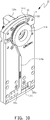
- FIG. 1(a) through FIG. 12(d) illustrate one embodiment of a double-sided flat inductor assembly 10 comprising first workpiece inductor 12 and second workpiece inductor 14 respectively mounted in first inductor frame 16 and second inductor frame 18.
- first workpiece 90a in this example is also referred to as the skirt and the first workpiece inductor frame 16 is correspondingly labeled "SKIRT” in some of the figures.
- second workpiece 90b in this example is also referred to as the crown and the second workpiece inductor frame 18 is correspondingly labeled "CROWN" in some of the figures.
- the inductor frames are configured as required for use in a particular application and represented in the figures in one embodiment.
- first workpiece inductor 12 comprises a first inductor terminal section 12a (also referred to as skirt inductor foot 12a), first inductor riser section 12b (also referred to as skirt inductor leg 12b) and first inductor coil section 12c (also referred to as skirt coil 12c).
- first inductor terminal section 12a also referred to as skirt inductor foot 12a
- first inductor riser section 12b also referred to as skirt inductor leg 12b
- first inductor coil section 12c also referred to as skirt coil 12c
- second workpiece inductor 14 comprises a second inductor terminal section 14a (also referred to as crown inductor foot 14a), second inductor riser section 14b (also referred to as crown inductor leg 14b) and second inductor coil section 14c (also referred to as crown coil 14c).
- second inductor terminal section 14a also referred to as crown inductor foot 14a
- second inductor riser section 14b also referred to as crown inductor leg 14b
- second inductor coil section 14c also referred to as crown coil 14c
- the first inductor riser section and the second inductor riser section are optional in other embodiments and are a means for electrically interconnecting the first inductor coil section to the first inductor terminal section, and the second inductor coil section to the second inductor terminal section, respectively, if there is a requirement to physically separate the inductor coil sections from the inductor terminal sections.
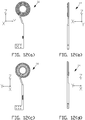
- first and second inductor coil sections 12c and 14c are each shaped as a spirally-coiled induction coil (or inductor) that is sometimes referred to as a "pancake" coil.
- the spacing between turns of the spirally-coiled inductor may vary based upon the workpiece geometry being heat treated. For example symmetric spacing between all turns of the coil can result in an electromagnetic ring effect where stronger magnetic fields occur on the inner radial region of the workpiece face being heat treated compared with the outer radial regions. To compensate in some embodiments the outer turns may be more closely spaced together than the inner turns. For example in FIG.
- the two outer turns of the first inductor coil sections 12c' and 12c" are more closely spaced together, and separated further apart from the single inner coil turn 12c'" to provide a more uniform induction heating across the surface (or face) of the workpiece with reduced sensitivity in coil position relative to the surface of the workpiece.
- other coil turn arrangements can be provided to compensate for selected regions of the first or second workpiece in a particular application.
- first inductor coil section and the second inductor coil section can be referred to as planarly oriented coil section with the two planarly oriented coil sections being planarly disposed opposing each other. Deviations from planar, for example, the profiling described herein are within the terminology of a planarly oriented coil section. While the embodiment of the inductor coil sections shown in the drawings is circular other configurations can be used in other embodiments. In other embodiments the entire first workpiece inductor and the entire second workpiece inductor can be referred to as planarly oriented inductors with the two planarly oriented inductors being planarly disposed opposing each other.
- First and second workpiece inductors are suitably joined together electrically, for example, by brazing to form a series electrical circuit between the first and second inductor terminal sections 12a and 14a.
- First workpiece inductor 12 and second workpiece inductor 14 are connected electrically in series as diagrammatically shown in FIG. 16 for orientation of electrical current through the inductors that allows magnetic fluxes generated by each inductor to complement each other rather than allowing maximum density of alternating current electrical current density to shift towards respected turns of the two inductors that results in a dramatic reduction of heating efficiency of respected areas of the first (skirt) workpiece 90a and the second (crown) workpiece 90b.
- first inductor riser section 12b includes riser-coil interface subsection 12b'.
- second inductor riser section 14b includes riser-coil interface subsection 14b'.
- crown inductor foot 14a is preferably flush with the outer surface of skirt inductor foot 12a on the SKIRT side of the inductor assembly to facilitate connections to a single phase alternating current source (not shown in the figures) in some embodiments.
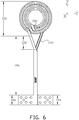
- the inner coil terminus 12c' of skirt coil 12c is electrically connected to the inner coil terminus 14c' of crown coil 14c as shown in FIG. 6 , 7 and 8 by electrical connecting element 13, which as mentioned above, can be accomplished by brazing the inner coil termini of the first and second inductor coils to form a series circuit from the skirt inductor 12 and crown inductor 14 between skirt terminal section 12a and crown terminal section 14a, which are connected to the outputs of a suitable single phase alternating current power source.
- inner coil terminus 12c' to inner coil terminus 14c' can be accomplished by any suitable means, for example by brazing (that is, forming a brazed joint between the inner coil terminus of the skirt inductor 12 and the inner coil terminus of the crown inductor 14).
- Alternative means of electrically connecting the two inductor coils in series can be, for example, an electrical conductor suitably connected between the inner coil termini or other coil termini for other inductor coil arrangements.
- Suitable middle electrical insulating material 94 is positioned as required between: (1) the skirt inductor foot 12a, skirt inductor leg 12b and skirt coil 12c; and (2) the crown inductor foot 14a, crown inductor leg 14b and crown coil 14c to provide a means of electrical isolation between skirt inductor 12 and crown inductor 14.
- Any other type of insulating material (dielectric), including air, can be used in other embodiments to provided electrical isolation between the skirt and crown inductor.
- first 16 and second 18 inductor frames are each formed from a non-electrically conductive material such as a phenolic board or a GLASTIC® electrical insulating board.
- FIG. 1(b) illustrates in cross section in this embodiment, inner skirt and crown concentrators 12d and 14d respectively; skirt and crown center plugs 12e and 14e respectively; and skirt and crown coils 12c and 14c respectively.
- the inner skirt and crown concentrators as shown in FIG. 1(b) provide maximum magnetic intensity on the respective inductor coil section when flush with the heating face (12c face or 14c face ) of the respective inductor coil section's inner turn. If the inner face of a particular workpiece surface to be heat treated is too hot, the inner concentrators can be repositioned or re-sized to reduce the heating efficiency of the inner turn of the inductor coil section to provide a means of controlling the induction heating process that can rectify heating imbalance between the radial inner and outer workpiece faces.
- one or more of the L-shaped concentrators used in this embodiment can have the top of an L-shaped concentrator shortened adjacent to its respective heating face to selectively reduce the magnetic intensity for a particular induction heating application.
- the concentrators can be other than L-shaped to suit a particular induction heating application.
- FIG. 3(b) illustrates in cross section in this embodiment, electrical insulating material 92a and 92b electrically separating skirt inductor foot 12a from crown inductor foot 14a.
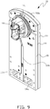
- FIG. 9 and FIG. 10 also illustrate how in this embodiment crown inductor foot 14a is flush with the outer surface of skirt inductor foot 12a on the SKIRT side of the inductor assembly in FIG. 9 to facilitate connections to a single phase alternating current source either directly (not shown in the figure) or via an extraction assembly as described herein while skirt inductor foot 12a does not extend to the crown inductor side as indicated by open space 18b in crown inductor frame 18 in FIG. 10 .
- Assembly of the first and second workpiece inductors and the first and second inductor frames can be, for example, by bolted (or other suitable fastening means) construction.
- FIG. 9 and FIG. 10 illustrate first (skirt) workpiece 90a in position over skirt coil 12c for induction heating of the first workpiece 90a simultaneously with the induction heating of the second (crown) workpiece 90b in position over crown coil 14c, and also in end view in FIG. 11 where the recessed skirt coil and crown coil are not visible.
- skirt inductor coil 12c and crown inductor coil 14c are recessed respectively in skirt inductor frame 16 and crown inductor frame 18 as indicated by frame recess regions 16a and 18a, for example in FIG. 2 and FIG. 4 respectively.
- the geometry of either workpiece can be non-uniform and have substantial changes in mass at various radial quadrants of the workpiece. These changes in mass create heat imbalances during heating.
- the heating surfaces of the respective inductor coil section can be profiled in angular radial quadrants to form a profiled section or region correlating to the different workpiece quadrants of varying mass.
- the workpiece must then be placed in the induction heating position at a specified orientation to maintain the desired inductor coil section to workpiece relationship.
- Inductor assembly 10 can be connected to actuator apparatus that moves the inductor assembly into the heat position between the first and second workpieces (shown in FIG. 11 ) and a retracted position downwards (in the negative Z-direction) so that facing skirt 90a and crown 90b heated surfaces can be simultaneously pushed together (in opposing X-directions) and twisted about the X-axis to join the skirt 90a and crown 90b.
- actuator apparatus that moves the inductor assembly into the heat position between the first and second workpieces (shown in FIG. 11 ) and a retracted position downwards (in the negative Z-direction) so that facing skirt 90a and crown 90b heated surfaces can be simultaneously pushed together (in opposing X-directions) and twisted about the X-axis to join the skirt 90a and crown 90b.
- one of the two workpieces can remain stationary and the other workpiece can be moved to push against the stationary workpiece.
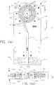
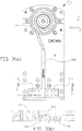
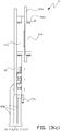
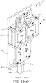
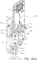
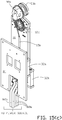
- the actuator apparatus is illustrated in one embodiment of the invention in FIG. 13(a) through FIG. 13(d) as double-sided inductor extraction assembly 30.
- Primary magnetic device 32a is suitably mounted to fixed structure such as primary mounting plate 81 that can be formed from a dielectric.
- Primary supply electrical conductors 86a and 86b are also mounted to primary mounting plate 81 (via standoff posts 81a in this embodiment).
- Primary supply electrical conductors are illustrated as bus bars in the example and can be any type of suitable electrical conductors.
- Power source cables 82a and 82b (three supply and three return cables in this embodiment) from a suitable single phase alternating current source are connected respectively to electrical conductors 86a and 86b.
- Power source cables can be any type of suitable power source electrical conductors such as bus bars.
- Secondary magnetic device 32b is electrically connected to secondary output electrical conductors 88a and 88b.
- the secondary magnetic device and secondary output electrical conductors are connected to a suitable extraction actuator (not shown in the drawings) which in this embodiment moves the secondary magnetic device and secondary output electrical conductors linearly in the plus or minus Z direction as further described below.
- the extraction movement may be in another linear direction, a rotational direction or a combination of linear and rotational directions.
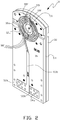
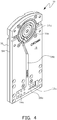
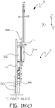
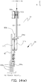
- FIG. 14(a) through FIG. 14(e) illustrate one example of double-sided flat inductor assembly 10 electrically connected to the extraction assembly shown in FIG. 13(a) through FIG. 13(d) .
- first inductor terminal section 12a and second inductor terminal section 14a are connected respectively to electrically conductors 88a and 88b on extraction assembly 30.
- Optional cooling fluid medium cables 84a and 84b and 84c and 84d supply and return a cooling fluid medium to the skirt and crown inductors via the extraction assembly in this example.
- extraction assembly 30 and attached double-sided flat inductor assembly 10 are shown in the induction heating position with the workpieces in place for induction heating as shown in FIG. 14(d) and 14(e) with the primary magnetic device aligned with the secondary magnetic device for flux transfer between the supply and return power magnetic devices and the inductor supply and return power magnetic devices.
- the inductor extraction actuator moves the secondary magnetic device and secondary output electrical conductors with the attached double-sided flat inductor assembly 10 downwards to the inductor assembly (induction post-heat) extracted position where the double-sided flat inductor assembly does not interfere with mating of the two workpieces in an industrial process after being induction heated, for example, when moving the two workpieces together.
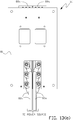
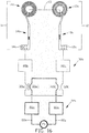
- FIG. 16 is one example of an electrical circuit for the components of the double-sided inductor extraction assembly shown in the figures.
- the primary and secondary magnetic devices each comprise two electrically isolated magnetic devices.
- the extraction assembly is in the induction heating position and alternating current is supplied via power source cables 82a and 82b the supply and return electrical circuit to the double-sided flat inductor assembly is completed by flux coupling between the primary magnetic devices and the secondary magnetic devices.
- the extraction assembly 30 moves inductor assembly 10 to the induction post-heat extracted position there is no magnetic flux coupling between the primary magnetic devices and the secondary magnetic devices while the inductor assembly is clear of the space between the two induction heated workpieces.
- This method of inductor assembly extraction provides a high speed method of clearing the space between the two induction heated workpieces while electromagnetically disconnecting a supply of power to the inductor assembly in comparison with mechanical movement of an entire inductor assembly, including, for example, bus work and power cables connected to a power source.
- extraction assembly 30 begins to transition inductor assembly 10 from the induction heating position to the inductor assembly (induction post-heat) extracted position, alternating current output power from power source PS in FIG. 16 could be turned off and the extracted inductors 12 and 14 on inductor assembly 10 would be powerless during the transition between the two positions.
- a depressed coil region in a coil planar face such as V-notches 99 shown in FIG. 1(a), FIG. 1(b) and FIG. 2 can be provided in the coil for clearance as the inductor retracts.
- the workpiece facing the coil can be rotated in the induction heating position during heating to ensure that workpiece surface region facing a V-notch region are sufficiently heated.
- the circumferential component of the induced eddy current could provide a sufficient heating effect of the workpiece region that corresponds to the V-notch location, and therefore eliminating a need for workpiece rotation during heating.
- first inductor coil section 12c has profiled regions, for example, at the top of the coil that are profiled (contoured) regions 99' in the X-direction (that is, the height of the induction coil section). Regions 99' are raised above the normal face heating plane of coil section 12c on either side of V-notches 99 to compensate for low induced heat in the regions of the coil V-notches. Such profiling can be used to conform to the face of the coil section adjacent to the face of the workpiece being heated.
- the first and second coil sections may be of other shapes and contours to suit the shape of the corresponding first and second workpieces to heat each workpiece by proximity heating.
- regions 98 in order to improve the heat uniformity in the transition regions 98 ( FIG. 1(a) and FIG. 2 ) where there is a transition between the outer turn-to-middle turn and middle-turn-to-inner turn of the pair of three turn coils that provide simultaneous heating of the first and second workpieces, there are profiled regions 98'.
- regions 98' are profiled in the X-direction and raised above the normal face heating plane of the coil section to compensate for lower heat intensity due to a reduced heat generation.
- electromagnetic coupling between primary magnetic device 32a and secondary magnetic device 32b allows the inductor to retract radially (Z-direction) away from the workpieces.
- the secondary magnetic device may be slidably mounted adjacent to a stationary primary magnetic device so that the secondary magnetic device can be slid downwards relative to the primary magnetic device.
- There is no physical contact between the primary and secondary devices which allows the secondary half that forms an electrically closed-loop circuit, with the double-sided inductor attached, to be quickly extended to the induction heating position and retracted to the induction post-heat extraction position. This is diagrammatically illustrated in circuit FIG.
- Each primary magnetic device can be any device that creates a magnetic flux from an alternating current flow through the device and each secondary magnetic device can be any device that magnetically couples the primary alternating magnetic flux for power transfer between the primary and secondary magnetic devices via transformer coupling without there being a physical connection between the primary magnetic devices and the secondary magnetic devices.
- each primary (32a' and 32a") and secondary (32b' and 32b”) magnetic device can be two joined magnetic C-cores to form a rectangular closed magnetic core with a central opening in which a portion of electrical conductors 86a, 86b, 88a or 88b are placed so that when alternating current flows through primary supply electrical conductors 86a and 86b a magnetic flux field is created that couples with the corresponding secondary magnetic device when extraction assembly 30 has positioned the inductors in the inductor assembly in the induction heating position.
- Each primary and secondary magnetic device may also be refered to as a coil wound core.
- skirt and crown are used interchangeably herein with other pairs of workpieces where it is advantageous to simultaneously induction heat the two workpieces. Further the process following the simultaneous heating may be joining the opposing faces of the workpieces together, but is not limited to that process as long as the process can benefit from the simultaneous induction heating.
- the extraction assembly of the present invention may be used with other configurations and quantity of inductors in an induction assembly in industrial processes where high speed transfer of the inductor assembly from an induction heating position to a workpiece non-interference position where the workpiece can be further processed is desirable.
- the number of coil turns can be singular or any multiple number of turns. In other embodiments the number of coil turns may be different for each coil in the pair of coils.
Landscapes
- Physics & Mathematics (AREA)
- Electromagnetism (AREA)
- General Induction Heating (AREA)
Priority Applications (1)
| Application Number | Priority Date | Filing Date | Title |
|---|---|---|---|
| PL15765571T PL3120664T3 (pl) | 2014-03-21 | 2015-03-18 | Dwustronny płaski zespół wzbudników |
Applications Claiming Priority (2)
| Application Number | Priority Date | Filing Date | Title |
|---|---|---|---|
| US201461968657P | 2014-03-21 | 2014-03-21 | |
| PCT/US2015/021297 WO2015143059A1 (en) | 2014-03-21 | 2015-03-18 | Double-sided flat inductor assembly |
Publications (3)
| Publication Number | Publication Date |
|---|---|
| EP3120664A1 EP3120664A1 (en) | 2017-01-25 |
| EP3120664A4 EP3120664A4 (en) | 2018-02-28 |
| EP3120664B1 true EP3120664B1 (en) | 2020-10-07 |
Family
ID=54143479
Family Applications (1)
| Application Number | Title | Priority Date | Filing Date |
|---|---|---|---|
| EP15765571.3A Not-in-force EP3120664B1 (en) | 2014-03-21 | 2015-03-18 | Double-sided flat inductor assembly |
Country Status (11)
| Country | Link |
|---|---|
| US (3) | US10251222B2 (enExample) |
| EP (1) | EP3120664B1 (enExample) |
| JP (1) | JP2017515288A (enExample) |
| KR (2) | KR20160136387A (enExample) |
| CN (1) | CN106416427B (enExample) |
| BR (1) | BR112016021554A8 (enExample) |
| CA (1) | CA2942945A1 (enExample) |
| ES (1) | ES2829826T3 (enExample) |
| MX (1) | MX2016012184A (enExample) |
| PL (1) | PL3120664T3 (enExample) |
| WO (1) | WO2015143059A1 (enExample) |
Families Citing this family (2)
| Publication number | Priority date | Publication date | Assignee | Title |
|---|---|---|---|---|
| WO2015143059A1 (en) * | 2014-03-21 | 2015-09-24 | Inductoheat, Inc. | Double-sided flat inductor assembly |
| USD949300S1 (en) * | 2020-07-10 | 2022-04-19 | Shenzhen Eigate Technology Co., Ltd. | Handle for high-frequency heating element |
Family Cites Families (22)
| Publication number | Priority date | Publication date | Assignee | Title |
|---|---|---|---|---|
| BE495722A (enExample) * | 1949-05-14 | |||
| US2866880A (en) | 1957-03-21 | 1958-12-30 | Leonidas C Miller | Clamp fixture for water-cooled induction coil |
| BE791284A (fr) * | 1972-11-13 | 1973-05-14 | Elphiac Sa | Systeme d'ajustement de la position d'un inducteur. |
| US4012616A (en) * | 1975-01-02 | 1977-03-15 | General Electric Company | Method for metal bonding |
| US4661668A (en) * | 1985-10-01 | 1987-04-28 | The Taylor-Winfield Corporation | Welding intercell connections by induction heating |
| US4728760A (en) * | 1986-08-11 | 1988-03-01 | Fmc Corporation | Induction heating pressure welding with rotary bus bar joint |
| JPH084033B2 (ja) * | 1988-09-16 | 1996-01-17 | 富士電機株式会社 | ダイスの誘導加熱装置 |
| US5451749A (en) | 1993-12-27 | 1995-09-19 | Tocco, Inc. | Inductor for inductively heating crank shafts |
| US5410134A (en) | 1994-07-25 | 1995-04-25 | L.C. Miller Company | Clamp for a water-cooled induction coil |
| US5523546A (en) * | 1995-05-09 | 1996-06-04 | Mannings, U.S.A., Inc. | Apparatus and method of inductively heating a workpiece with a slender bone |
| JP3757506B2 (ja) * | 1996-12-24 | 2006-03-22 | 株式会社日立製作所 | 耐熱合金の接合法 |
| AU764537B2 (en) | 1998-11-02 | 2003-08-21 | Industrial Field Robotics | Improved method of solid state welding and welded parts |
| US6825450B2 (en) | 2002-11-06 | 2004-11-30 | Federal-Mogul World Wide, Inc. | Piston and method of manufacture |
| WO2004075605A2 (en) * | 2003-02-14 | 2004-09-02 | Inductoheat Inc. | Induction heat treatment of complex-shaped workpieces |
| US7005620B2 (en) | 2003-11-04 | 2006-02-28 | Federal-Mogul World Wide, Inc. | Piston and method of manufacture |
| US8614409B2 (en) | 2004-10-27 | 2013-12-24 | Induction Tooling, Inc. | Induction heating device with electromagnetic diverter |
| DE102005005527A1 (de) | 2005-01-31 | 2006-08-03 | E.G.O. Elektro-Gerätebau GmbH | Induktionsheizeinrichtung und Kochfeldmulde mit einer solchen Induktionsheizeinrichtung |
| US8115147B2 (en) | 2005-06-03 | 2012-02-14 | Illinois Tool Works Inc. | Induction heating system output control based on induction heating device |
| ATE532598T1 (de) | 2006-09-18 | 2011-11-15 | Spinduction Weld Inc | Vorrichtung zur feststoffschweissung mit induktionsreibung |
| GB0712225D0 (en) | 2007-06-23 | 2007-08-01 | Rolls Royce Plc | Welding enclosure |
| US9474109B2 (en) | 2012-08-13 | 2016-10-18 | Tokuden Co., Ltd. | Induction heating apparatus |
| WO2015143059A1 (en) * | 2014-03-21 | 2015-09-24 | Inductoheat, Inc. | Double-sided flat inductor assembly |
-
2015
- 2015-03-18 WO PCT/US2015/021297 patent/WO2015143059A1/en not_active Ceased
- 2015-03-18 CA CA2942945A patent/CA2942945A1/en not_active Abandoned
- 2015-03-18 EP EP15765571.3A patent/EP3120664B1/en not_active Not-in-force
- 2015-03-18 KR KR1020167029328A patent/KR20160136387A/ko not_active Ceased
- 2015-03-18 KR KR1020207007546A patent/KR20200038518A/ko not_active Ceased
- 2015-03-18 ES ES15765571T patent/ES2829826T3/es active Active
- 2015-03-18 MX MX2016012184A patent/MX2016012184A/es unknown
- 2015-03-18 US US14/661,736 patent/US10251222B2/en active Active
- 2015-03-18 JP JP2017501098A patent/JP2017515288A/ja active Pending
- 2015-03-18 BR BR112016021554D patent/BR112016021554A8/pt not_active IP Right Cessation
- 2015-03-18 PL PL15765571T patent/PL3120664T3/pl unknown
- 2015-03-18 CN CN201580025654.2A patent/CN106416427B/zh not_active Expired - Fee Related
-
2019
- 2019-03-31 US US16/371,015 patent/US20190230748A1/en not_active Abandoned
- 2019-03-31 US US16/371,013 patent/US11191131B2/en active Active
Non-Patent Citations (1)
| Title |
|---|
| None * |
Also Published As
| Publication number | Publication date |
|---|---|
| ES2829826T3 (es) | 2021-06-02 |
| CA2942945A1 (en) | 2015-09-24 |
| EP3120664A1 (en) | 2017-01-25 |
| CN106416427B (zh) | 2020-04-07 |
| JP2017515288A (ja) | 2017-06-08 |
| KR20200038518A (ko) | 2020-04-13 |
| PL3120664T3 (pl) | 2021-01-25 |
| CN106416427A (zh) | 2017-02-15 |
| US11191131B2 (en) | 2021-11-30 |
| BR112016021554A8 (pt) | 2021-05-18 |
| US20190230747A1 (en) | 2019-07-25 |
| WO2015143059A1 (en) | 2015-09-24 |
| KR20160136387A (ko) | 2016-11-29 |
| US20150271875A1 (en) | 2015-09-24 |
| US10251222B2 (en) | 2019-04-02 |
| EP3120664A4 (en) | 2018-02-28 |
| MX2016012184A (es) | 2017-01-05 |
| US20190230748A1 (en) | 2019-07-25 |
Similar Documents
| Publication | Publication Date | Title |
|---|---|---|
| RU2407635C2 (ru) | Устройство для обработки материалов с использованием индукционного нагрева | |
| US20120025428A1 (en) | Device for transforming materials by induction heating | |
| JP2015521551A (ja) | 迅速加熱冷却金型 | |
| EP3477669B1 (en) | High power capacitor | |
| US11191131B2 (en) | Double-sided flat inductor assembly | |
| CN101766050A (zh) | 感应加热器 | |
| CN104191081A (zh) | 用于制冷设备中铜管与铝管焊接的装置及其焊接方法 | |
| KR101658727B1 (ko) | 이동형 철심을 이용한 초전도 자석 장치 및 그의 유도가열장치 | |
| US8716636B2 (en) | Arrangement and method for powering inductors for induction hardening | |
| US20190289682A1 (en) | Inductors and inductor extraction assemblies | |
| EP3005830B1 (en) | Heater apparatus and controllable heating process | |
| JP2016127078A (ja) | コイル装置 | |
| US8178038B2 (en) | Undercut crankshaft hardening coil | |
| CN204094300U (zh) | 用于制冷设备中铜管与铝管焊接的装置 | |
| JP2015084312A (ja) | ロータコア加熱装置及びロータコア焼き嵌め方法 | |
| Patil et al. | A Critical review on different coil configurations used for induction heating system | |
| CN106783096A (zh) | 一种漏磁补偿结构 | |
| CN206541724U (zh) | 一种漏磁补偿结构 | |
| CN205914861U (zh) | 高周波焊接装置的焊头结构及其磁场屏蔽组件 | |
| JP2011140054A (ja) | 高周波誘導加熱による接合方法及び接合装置 | |
| CN202679687U (zh) | 一种使用电磁感应加热待加工材料的设备 | |
| Qiu et al. | A comparative study of flux cancellation among multiple interconnected modular pads in lumped IPT system | |
| WO2025153709A1 (en) | High power density induction heater | |
| CN204045358U (zh) | 小型单相节能变压器 | |
| CN110556735A (zh) | 隔爆电器的腔板非磁材料充填涡流阻隔工艺 |
Legal Events
| Date | Code | Title | Description |
|---|---|---|---|
| STAA | Information on the status of an ep patent application or granted ep patent |
Free format text: STATUS: THE INTERNATIONAL PUBLICATION HAS BEEN MADE |
|
| PUAI | Public reference made under article 153(3) epc to a published international application that has entered the european phase |
Free format text: ORIGINAL CODE: 0009012 |
|
| STAA | Information on the status of an ep patent application or granted ep patent |
Free format text: STATUS: REQUEST FOR EXAMINATION WAS MADE |
|
| 17P | Request for examination filed |
Effective date: 20161017 |
|
| AK | Designated contracting states |
Kind code of ref document: A1 Designated state(s): AL AT BE BG CH CY CZ DE DK EE ES FI FR GB GR HR HU IE IS IT LI LT LU LV MC MK MT NL NO PL PT RO RS SE SI SK SM TR |
|
| AX | Request for extension of the european patent |
Extension state: BA ME |
|
| DAV | Request for validation of the european patent (deleted) | ||
| DAX | Request for extension of the european patent (deleted) | ||
| RIC1 | Information provided on ipc code assigned before grant |
Ipc: H05B 6/02 20060101AFI20171018BHEP Ipc: H05B 6/36 20060101ALI20171018BHEP Ipc: H05B 6/10 20060101ALI20171018BHEP Ipc: H05B 6/44 20060101ALI20171018BHEP |
|
| A4 | Supplementary search report drawn up and despatched |
Effective date: 20180129 |
|
| RIC1 | Information provided on ipc code assigned before grant |
Ipc: H05B 6/02 20060101AFI20180123BHEP Ipc: H05B 6/10 20060101ALI20180123BHEP Ipc: H05B 6/06 20060101ALI20180123BHEP Ipc: H05B 6/44 20060101ALI20180123BHEP Ipc: H05B 6/36 20060101ALI20180123BHEP |
|
| GRAP | Despatch of communication of intention to grant a patent |
Free format text: ORIGINAL CODE: EPIDOSNIGR1 |
|
| STAA | Information on the status of an ep patent application or granted ep patent |
Free format text: STATUS: GRANT OF PATENT IS INTENDED |
|
| RIC1 | Information provided on ipc code assigned before grant |
Ipc: H05B 6/10 20060101ALI20200615BHEP Ipc: H05B 6/44 20060101ALI20200615BHEP Ipc: H05B 6/02 20060101AFI20200615BHEP Ipc: H05B 6/06 20060101ALI20200615BHEP Ipc: H05B 6/36 20060101ALI20200615BHEP |
|
| INTG | Intention to grant announced |
Effective date: 20200630 |
|
| RIN1 | Information on inventor provided before grant (corrected) |
Inventor name: GOODWIN, JOHN AARON Inventor name: RUDNEV, VALERY I. |
|
| GRAS | Grant fee paid |
Free format text: ORIGINAL CODE: EPIDOSNIGR3 |
|
| GRAA | (expected) grant |
Free format text: ORIGINAL CODE: 0009210 |
|
| STAA | Information on the status of an ep patent application or granted ep patent |
Free format text: STATUS: THE PATENT HAS BEEN GRANTED |
|
| AK | Designated contracting states |
Kind code of ref document: B1 Designated state(s): AL AT BE BG CH CY CZ DE DK EE ES FI FR GB GR HR HU IE IS IT LI LT LU LV MC MK MT NL NO PL PT RO RS SE SI SK SM TR |
|
| REG | Reference to a national code |
Ref country code: GB Ref legal event code: FG4D |
|
| REG | Reference to a national code |
Ref country code: CH Ref legal event code: EP Ref country code: AT Ref legal event code: REF Ref document number: 1322604 Country of ref document: AT Kind code of ref document: T Effective date: 20201015 |
|
| REG | Reference to a national code |
Ref country code: IE Ref legal event code: FG4D |
|
| REG | Reference to a national code |
Ref country code: DE Ref legal event code: R096 Ref document number: 602015060172 Country of ref document: DE |
|
| REG | Reference to a national code |
Ref country code: SE Ref legal event code: TRGR |
|
| REG | Reference to a national code |
Ref country code: NL Ref legal event code: MP Effective date: 20201007 |
|
| REG | Reference to a national code |
Ref country code: AT Ref legal event code: MK05 Ref document number: 1322604 Country of ref document: AT Kind code of ref document: T Effective date: 20201007 |
|
| PG25 | Lapsed in a contracting state [announced via postgrant information from national office to epo] |
Ref country code: GR Free format text: LAPSE BECAUSE OF FAILURE TO SUBMIT A TRANSLATION OF THE DESCRIPTION OR TO PAY THE FEE WITHIN THE PRESCRIBED TIME-LIMIT Effective date: 20210108 Ref country code: FI Free format text: LAPSE BECAUSE OF FAILURE TO SUBMIT A TRANSLATION OF THE DESCRIPTION OR TO PAY THE FEE WITHIN THE PRESCRIBED TIME-LIMIT Effective date: 20201007 Ref country code: PT Free format text: LAPSE BECAUSE OF FAILURE TO SUBMIT A TRANSLATION OF THE DESCRIPTION OR TO PAY THE FEE WITHIN THE PRESCRIBED TIME-LIMIT Effective date: 20210208 Ref country code: RS Free format text: LAPSE BECAUSE OF FAILURE TO SUBMIT A TRANSLATION OF THE DESCRIPTION OR TO PAY THE FEE WITHIN THE PRESCRIBED TIME-LIMIT Effective date: 20201007 Ref country code: NO Free format text: LAPSE BECAUSE OF FAILURE TO SUBMIT A TRANSLATION OF THE DESCRIPTION OR TO PAY THE FEE WITHIN THE PRESCRIBED TIME-LIMIT Effective date: 20210107 Ref country code: NL Free format text: LAPSE BECAUSE OF FAILURE TO SUBMIT A TRANSLATION OF THE DESCRIPTION OR TO PAY THE FEE WITHIN THE PRESCRIBED TIME-LIMIT Effective date: 20201007 |
|
| REG | Reference to a national code |
Ref country code: LT Ref legal event code: MG4D |
|
| PG25 | Lapsed in a contracting state [announced via postgrant information from national office to epo] |
Ref country code: BG Free format text: LAPSE BECAUSE OF FAILURE TO SUBMIT A TRANSLATION OF THE DESCRIPTION OR TO PAY THE FEE WITHIN THE PRESCRIBED TIME-LIMIT Effective date: 20210107 Ref country code: AT Free format text: LAPSE BECAUSE OF FAILURE TO SUBMIT A TRANSLATION OF THE DESCRIPTION OR TO PAY THE FEE WITHIN THE PRESCRIBED TIME-LIMIT Effective date: 20201007 Ref country code: LV Free format text: LAPSE BECAUSE OF FAILURE TO SUBMIT A TRANSLATION OF THE DESCRIPTION OR TO PAY THE FEE WITHIN THE PRESCRIBED TIME-LIMIT Effective date: 20201007 Ref country code: IS Free format text: LAPSE BECAUSE OF FAILURE TO SUBMIT A TRANSLATION OF THE DESCRIPTION OR TO PAY THE FEE WITHIN THE PRESCRIBED TIME-LIMIT Effective date: 20210207 |
|
| REG | Reference to a national code |
Ref country code: ES Ref legal event code: FG2A Ref document number: 2829826 Country of ref document: ES Kind code of ref document: T3 Effective date: 20210602 |
|
| PG25 | Lapsed in a contracting state [announced via postgrant information from national office to epo] |
Ref country code: HR Free format text: LAPSE BECAUSE OF FAILURE TO SUBMIT A TRANSLATION OF THE DESCRIPTION OR TO PAY THE FEE WITHIN THE PRESCRIBED TIME-LIMIT Effective date: 20201007 |
|
| REG | Reference to a national code |
Ref country code: DE Ref legal event code: R097 Ref document number: 602015060172 Country of ref document: DE |
|
| PG25 | Lapsed in a contracting state [announced via postgrant information from national office to epo] |
Ref country code: SM Free format text: LAPSE BECAUSE OF FAILURE TO SUBMIT A TRANSLATION OF THE DESCRIPTION OR TO PAY THE FEE WITHIN THE PRESCRIBED TIME-LIMIT Effective date: 20201007 Ref country code: EE Free format text: LAPSE BECAUSE OF FAILURE TO SUBMIT A TRANSLATION OF THE DESCRIPTION OR TO PAY THE FEE WITHIN THE PRESCRIBED TIME-LIMIT Effective date: 20201007 Ref country code: CZ Free format text: LAPSE BECAUSE OF FAILURE TO SUBMIT A TRANSLATION OF THE DESCRIPTION OR TO PAY THE FEE WITHIN THE PRESCRIBED TIME-LIMIT Effective date: 20201007 Ref country code: LT Free format text: LAPSE BECAUSE OF FAILURE TO SUBMIT A TRANSLATION OF THE DESCRIPTION OR TO PAY THE FEE WITHIN THE PRESCRIBED TIME-LIMIT Effective date: 20201007 Ref country code: SK Free format text: LAPSE BECAUSE OF FAILURE TO SUBMIT A TRANSLATION OF THE DESCRIPTION OR TO PAY THE FEE WITHIN THE PRESCRIBED TIME-LIMIT Effective date: 20201007 |
|
| PLBE | No opposition filed within time limit |
Free format text: ORIGINAL CODE: 0009261 |
|
| STAA | Information on the status of an ep patent application or granted ep patent |
Free format text: STATUS: NO OPPOSITION FILED WITHIN TIME LIMIT |
|
| PG25 | Lapsed in a contracting state [announced via postgrant information from national office to epo] |
Ref country code: DK Free format text: LAPSE BECAUSE OF FAILURE TO SUBMIT A TRANSLATION OF THE DESCRIPTION OR TO PAY THE FEE WITHIN THE PRESCRIBED TIME-LIMIT Effective date: 20201007 |
|
| 26N | No opposition filed |
Effective date: 20210708 |
|
| PG25 | Lapsed in a contracting state [announced via postgrant information from national office to epo] |
Ref country code: AL Free format text: LAPSE BECAUSE OF FAILURE TO SUBMIT A TRANSLATION OF THE DESCRIPTION OR TO PAY THE FEE WITHIN THE PRESCRIBED TIME-LIMIT Effective date: 20201007 Ref country code: MC Free format text: LAPSE BECAUSE OF FAILURE TO SUBMIT A TRANSLATION OF THE DESCRIPTION OR TO PAY THE FEE WITHIN THE PRESCRIBED TIME-LIMIT Effective date: 20201007 |
|
| REG | Reference to a national code |
Ref country code: CH Ref legal event code: PL |
|
| GBPC | Gb: european patent ceased through non-payment of renewal fee |
Effective date: 20210318 |
|
| PG25 | Lapsed in a contracting state [announced via postgrant information from national office to epo] |
Ref country code: RO Free format text: LAPSE BECAUSE OF NON-PAYMENT OF DUE FEES Effective date: 20201007 Ref country code: SI Free format text: LAPSE BECAUSE OF FAILURE TO SUBMIT A TRANSLATION OF THE DESCRIPTION OR TO PAY THE FEE WITHIN THE PRESCRIBED TIME-LIMIT Effective date: 20201007 |
|
| REG | Reference to a national code |
Ref country code: BE Ref legal event code: MM Effective date: 20210331 |
|
| PG25 | Lapsed in a contracting state [announced via postgrant information from national office to epo] |
Ref country code: CH Free format text: LAPSE BECAUSE OF NON-PAYMENT OF DUE FEES Effective date: 20210331 Ref country code: LU Free format text: LAPSE BECAUSE OF NON-PAYMENT OF DUE FEES Effective date: 20210318 Ref country code: LI Free format text: LAPSE BECAUSE OF NON-PAYMENT OF DUE FEES Effective date: 20210331 Ref country code: SE Free format text: LAPSE BECAUSE OF NON-PAYMENT OF DUE FEES Effective date: 20210319 Ref country code: GB Free format text: LAPSE BECAUSE OF NON-PAYMENT OF DUE FEES Effective date: 20210318 Ref country code: IE Free format text: LAPSE BECAUSE OF NON-PAYMENT OF DUE FEES Effective date: 20210318 Ref country code: FR Free format text: LAPSE BECAUSE OF NON-PAYMENT OF DUE FEES Effective date: 20210331 |
|
| PGFP | Annual fee paid to national office [announced via postgrant information from national office to epo] |
Ref country code: DE Payment date: 20220209 Year of fee payment: 8 |
|
| REG | Reference to a national code |
Ref country code: ES Ref legal event code: FD2A Effective date: 20220523 |
|
| PG25 | Lapsed in a contracting state [announced via postgrant information from national office to epo] |
Ref country code: IS Free format text: LAPSE BECAUSE OF FAILURE TO SUBMIT A TRANSLATION OF THE DESCRIPTION OR TO PAY THE FEE WITHIN THE PRESCRIBED TIME-LIMIT Effective date: 20210207 |
|
| PG25 | Lapsed in a contracting state [announced via postgrant information from national office to epo] |
Ref country code: ES Free format text: LAPSE BECAUSE OF NON-PAYMENT OF DUE FEES Effective date: 20210319 Ref country code: BE Free format text: LAPSE BECAUSE OF NON-PAYMENT OF DUE FEES Effective date: 20210331 |
|
| PG25 | Lapsed in a contracting state [announced via postgrant information from national office to epo] |
Ref country code: IT Free format text: LAPSE BECAUSE OF NON-PAYMENT OF DUE FEES Effective date: 20210318 |
|
| PG25 | Lapsed in a contracting state [announced via postgrant information from national office to epo] |
Ref country code: PL Free format text: LAPSE BECAUSE OF NON-PAYMENT OF DUE FEES Effective date: 20210318 Ref country code: HU Free format text: LAPSE BECAUSE OF FAILURE TO SUBMIT A TRANSLATION OF THE DESCRIPTION OR TO PAY THE FEE WITHIN THE PRESCRIBED TIME-LIMIT; INVALID AB INITIO Effective date: 20150318 |
|
| PG25 | Lapsed in a contracting state [announced via postgrant information from national office to epo] |
Ref country code: CY Free format text: LAPSE BECAUSE OF FAILURE TO SUBMIT A TRANSLATION OF THE DESCRIPTION OR TO PAY THE FEE WITHIN THE PRESCRIBED TIME-LIMIT Effective date: 20201007 |
|
| REG | Reference to a national code |
Ref country code: DE Ref legal event code: R119 Ref document number: 602015060172 Country of ref document: DE |
|
| PG25 | Lapsed in a contracting state [announced via postgrant information from national office to epo] |
Ref country code: DE Free format text: LAPSE BECAUSE OF NON-PAYMENT OF DUE FEES Effective date: 20231003 |
|
| PG25 | Lapsed in a contracting state [announced via postgrant information from national office to epo] |
Ref country code: MK Free format text: LAPSE BECAUSE OF FAILURE TO SUBMIT A TRANSLATION OF THE DESCRIPTION OR TO PAY THE FEE WITHIN THE PRESCRIBED TIME-LIMIT Effective date: 20201007 |
|
| PG25 | Lapsed in a contracting state [announced via postgrant information from national office to epo] |
Ref country code: TR Free format text: LAPSE BECAUSE OF NON-PAYMENT OF DUE FEES Effective date: 20210318 Ref country code: MT Free format text: LAPSE BECAUSE OF FAILURE TO SUBMIT A TRANSLATION OF THE DESCRIPTION OR TO PAY THE FEE WITHIN THE PRESCRIBED TIME-LIMIT Effective date: 20201007 |