EP3120275B1 - System for ligament insertion in knee joint surgeries using adaptive migration of ligament insertion geometry - Google Patents
System for ligament insertion in knee joint surgeries using adaptive migration of ligament insertion geometry Download PDFInfo
- Publication number
- EP3120275B1 EP3120275B1 EP15765035.9A EP15765035A EP3120275B1 EP 3120275 B1 EP3120275 B1 EP 3120275B1 EP 15765035 A EP15765035 A EP 15765035A EP 3120275 B1 EP3120275 B1 EP 3120275B1
- Authority
- EP
- European Patent Office
- Prior art keywords
- ligament
- knee joint
- geometry
- strain
- adaptive migration
- Prior art date
- Legal status (The legal status is an assumption and is not a legal conclusion. Google has not performed a legal analysis and makes no representation as to the accuracy of the status listed.)
- Active
Links
Images


Classifications
-
- A—HUMAN NECESSITIES
- A61—MEDICAL OR VETERINARY SCIENCE; HYGIENE
- A61B—DIAGNOSIS; SURGERY; IDENTIFICATION
- A61B34/00—Computer-aided surgery; Manipulators or robots specially adapted for use in surgery
- A61B34/10—Computer-aided planning, simulation or modelling of surgical operations
-
- A—HUMAN NECESSITIES
- A61—MEDICAL OR VETERINARY SCIENCE; HYGIENE
- A61B—DIAGNOSIS; SURGERY; IDENTIFICATION
- A61B17/00—Surgical instruments, devices or methods
- A61B17/16—Instruments for performing osteoclasis; Drills or chisels for bones; Trepans
- A61B17/17—Guides or aligning means for drills, mills, pins or wires
- A61B17/1714—Guides or aligning means for drills, mills, pins or wires for applying tendons or ligaments
-
- A—HUMAN NECESSITIES
- A61—MEDICAL OR VETERINARY SCIENCE; HYGIENE
- A61B—DIAGNOSIS; SURGERY; IDENTIFICATION
- A61B17/00—Surgical instruments, devices or methods
- A61B17/16—Instruments for performing osteoclasis; Drills or chisels for bones; Trepans
- A61B17/17—Guides or aligning means for drills, mills, pins or wires
- A61B17/1739—Guides or aligning means for drills, mills, pins or wires specially adapted for particular parts of the body
- A61B17/1764—Guides or aligning means for drills, mills, pins or wires specially adapted for particular parts of the body for the knee
-
- A—HUMAN NECESSITIES
- A61—MEDICAL OR VETERINARY SCIENCE; HYGIENE
- A61B—DIAGNOSIS; SURGERY; IDENTIFICATION
- A61B5/00—Measuring for diagnostic purposes; Identification of persons
- A61B5/103—Measuring devices for testing the shape, pattern, colour, size or movement of the body or parts thereof, for diagnostic purposes
- A61B5/11—Measuring movement of the entire body or parts thereof, e.g. head or hand tremor or mobility of a limb
- A61B5/1121—Determining geometric values, e.g. centre of rotation or angular range of movement
-
- A—HUMAN NECESSITIES
- A61—MEDICAL OR VETERINARY SCIENCE; HYGIENE
- A61B—DIAGNOSIS; SURGERY; IDENTIFICATION
- A61B5/00—Measuring for diagnostic purposes; Identification of persons
- A61B5/45—For evaluating or diagnosing the musculoskeletal system or teeth
- A61B5/4528—Joints
-
- A—HUMAN NECESSITIES
- A61—MEDICAL OR VETERINARY SCIENCE; HYGIENE
- A61B—DIAGNOSIS; SURGERY; IDENTIFICATION
- A61B5/00—Measuring for diagnostic purposes; Identification of persons
- A61B5/45—For evaluating or diagnosing the musculoskeletal system or teeth
- A61B5/4533—Ligaments
-
- A—HUMAN NECESSITIES
- A61—MEDICAL OR VETERINARY SCIENCE; HYGIENE
- A61B—DIAGNOSIS; SURGERY; IDENTIFICATION
- A61B5/00—Measuring for diagnostic purposes; Identification of persons
- A61B5/45—For evaluating or diagnosing the musculoskeletal system or teeth
- A61B5/4538—Evaluating a particular part of the muscoloskeletal system or a particular medical condition
- A61B5/4585—Evaluating the knee
-
- A—HUMAN NECESSITIES
- A61—MEDICAL OR VETERINARY SCIENCE; HYGIENE
- A61B—DIAGNOSIS; SURGERY; IDENTIFICATION
- A61B34/00—Computer-aided surgery; Manipulators or robots specially adapted for use in surgery
- A61B34/10—Computer-aided planning, simulation or modelling of surgical operations
- A61B2034/101—Computer-aided simulation of surgical operations
- A61B2034/105—Modelling of the patient, e.g. for ligaments or bones
-
- A—HUMAN NECESSITIES
- A61—MEDICAL OR VETERINARY SCIENCE; HYGIENE
- A61B—DIAGNOSIS; SURGERY; IDENTIFICATION
- A61B34/00—Computer-aided surgery; Manipulators or robots specially adapted for use in surgery
- A61B34/10—Computer-aided planning, simulation or modelling of surgical operations
- A61B2034/107—Visualisation of planned trajectories or target regions
-
- A—HUMAN NECESSITIES
- A61—MEDICAL OR VETERINARY SCIENCE; HYGIENE
- A61B—DIAGNOSIS; SURGERY; IDENTIFICATION
- A61B2505/00—Evaluating, monitoring or diagnosing in the context of a particular type of medical care
- A61B2505/05—Surgical care
Definitions
- the present invention relates to a system for ligament insertion in knee joint surgeries, and more particularly to ligament insertion in knee joint surgeries that uses adaptive migration of ligament insertion geometry.
- a system for providing feedback during ligament insertion in knee joint orthopedic surgeries according to the preamble part of claim 1 is known from US 2006/0161052 A1 .
- the knee joint is one of the most important and strongest joints in the human body. It is designed to support the weight of a person's body and to provide articulating motion between the upper leg and the lower leg.
- human knee joint 10 provides a hinged connection between the femur bone 102 of the upper leg and the tibia 104 and fibular 106 bones of the lower leg.
- the bone anatomy of the knee joint also includes the patella bone 108 located in the center of the knee.
- the distal end of the femur bone 102 includes two convex epicondyles, i.e., lateral epicondyle 126 and medial epicondyle 127 that interface and articulate with two corresponding condyles formed at the proximal end of the tibia bone 104, i.e., lateral condyle and medial condyle, respectively.
- the end surfaces of the condyles and epicondyles are covered by the articular cartilage 124 and between the femur and the tibia there is a plate of cartilage known as the meniscus 122.
- the knee joint bones are held together by a series of ligaments including the medial collateral ligament (MCL) 110, the lateral collateral ligament (LCL) 112, the anterior cruciate ligament (ACL) 114, the posterior cruciate ligament (PCL) 116, the patella tendon 118 and the quadriceps tendon 120.
- MCL medial collateral ligament
- LCL anterior cruciate ligament
- PCL posterior cruciate ligament
- the MCL connects the medial site of the femur to the tibia.
- the LCL connects the lateral site of the femur to the fibula.
- the ACL extends obliquely from and connects the inner surface of the lateral epicondyle of the femur to the anterior condyle of the tibia.
- the PCL extends obliquely from and connects the inner surface of the medial epicondyle of the femur to the posterior condyle of the tibia.
- the patella bone is held in place in the anterior surface of the knee by the patellar tendon and the quadriceps tendon.
- the overall range of motion of the knee depends upon the specific anatomy of the bones and the ligaments and in general it allows about 120° degrees of flexion motion.
- the ligaments and the fluid capsule and bursae are referred to as the soft tissue of the knee joint.
- the osseous landmarks are of surgical interest because they are palpable or possibly visible in the near vicinity of the ligament structure of interest. But generally these landmarks are not mechanical, or if they are, their function is secondary to the principle function of the joint or perhaps structural in nature.
- the shape of the contiguous articular surfaces constitutes a constraint system which guides or constrains the permissible kinematics of the joint (assuming no interpenetration which is not strictly true under load).
- the articular contact geometry coupled with the geometry of the ligament structure, functions synergistically to realize the requisite stability and conversely, mobility of the joint.
- TKA total knee arthroplasty
- accurate positioning of the implants and accurate ligament attachment are crucial to the success of the operations.
- a large percentage of these operations fail and need to be repeated because it is difficult to determine the accurate positioning of the implant and the accurate ligament attachment from purely anatomical data.
- This prior art system includes a position determining device that is capable of tracking relative movement of two bones using reference bodies that are attached to the bones and a pointer that has a tip for contacting a surface of at least one of the two bones in order to capture one or more reference points.
- the system also includes a computer that is configured to determine and track intraoperative positions of the reference bodies and the pointer and to provide isometric and impingement data for the ligament graft placement based on realistic simulation of a trajectory of a deformable ligament graft.
- the system generates and compares preoperative and postoperative plots that represent knee laxity as a function of flexion. However, in many cases the preoperative state of the knee and the surrounding soft tissue is already compromised and therefore trying to replicate the preoperative state of the knee joint may be not desirable.
- US 2006/0161052 A1 discloses a method and a system for computerized ligament reconstruction surgery.
- the system includes a position determining device that is capable of tracking the relative movements of the first and second bones using reference bodies that are attached to the first and second bones and a pointer that has a tip for contacting a surface of at least one of the first and second bones to capture one or more reference points.
- the system further includes a computer that is configured to determine and track intraoperative positions of the reference bodies and the pointer and to provide isometric and impingement data for a ligament graft placement based on a realistic simulation of a trajectory of a deformable ligament graft.
- isometry In ligament reconstruction surgeries, surgeons try to determine and locate tibia and femur points that would produce optimal isometry. Isometry exist when the distance between two points in the original configuration is the same as the distance between their corresponding images in the transformed configuration. In ligament reconstruction surgery, isometry involves replacing a resected ligament with a replacement ligament so that no length change occurs through a normal unrestricted motion arc. In general, the assumption is that it is desirable to maximized isometry in ligament reconstruction surgeries. However, this method does not always lead to successful ligament reconstruction because the initial configuration may not be optimal and because there are not truly isometric points in the knee joints.
- the present invention provides a system and a method of providing improved ligament reconstruction by utilizing an adaptive migration of ligament insertion geometry.
- the key hypotheses of the present methodology include the following:
- the adaptive migration approach involves exercising a geometric model of a knee joint through a prescribed motion path (where flexion, internal rotation, anterior posterior displacement and medial lateral motion are prescribed) while constrained in two degrees of freedom by the geometry of contact (abduction adduction and joint compression distraction).
- the prescribed motion path represents the passive kinematics of the knee through the flexion arc.
- the normal knee flexion arc extends from 0° to 135° to 145° degrees.
- a cost function based on the magnitude of strain is defined and the direction of action of the strain induced tension in each element is determined at each calculation step.
- Ligament insertion sites are migrated in a direction counterpoised to the line of action of the ligament tension throughout the flexion arc.
- This adaptive migration of the insertion sites acts such that the integral of strain over the flexion arc trends towards zero with successive iterations of the computation.
- an insertion site is determined which optimally balances tensile and compressive strain over the prescribed flexion arc.
- Element reference strain can be adjusted to produce an initially slack or initially tense element as might be required to represent the physiologically condition.
- the passive motion is assumed to involve minimal strain through the flexion arc.
- a more complex cost function is considered which balances counterpoised fibers to balance both the forces and moments acting across the joint as a result of ligament tension.
- the counterpoising strain cost when the joint reaches the limits of the range of motion in situations where the ligaments play a role in limiting that motion. As will be seen later this later case is easily accommodated such as in the case of the PCL in hyperextension which requires hypertonic fibers.
- the system 100 for knee joint simulation using the adaptive migration of ligament insertion geometry includes a computer 140 equipped with an adaptive migration application 150, inputs 130 and outputs 160.
- the inputs 130 to the adaptive migration optimization include:
- the outputs 160 from the adaptive migration optimization include: ⁇ Sets of near isotonic, hypertonic and hypotonic points representing the proximal (femoral) insertion sites of the ligament fibers associated with the prescribed distal ligament insertion sites 162.
- the knee joint articular surface geometry data is provided by an imaging device, such as X-ray, MRI, CT devices.
- the distal ligament insertion sites are provided by a position measuring device.
- the position measuring device may be an optical, acoustical, ultra-sound, video, mechanical, electromagnetic, shape recognition algorithm, or radio-frequency based emitter/detector system.
- the position measuring device is the Polaris system from Northern Digital Inc., Ontario, Canada.
- the ligament reference strain is provided by a strain measuring device, such as strain gauges, optical or magnetic devices.
- the prescribed kinematic path for the knee joint is provided by a drive system or a specific protocol.
- the adaptive migration application 150 based on the above mentioned methodology is implemented in MATLABTM.
- the model is quasi three-dimensional (3D) in that independent medial and lateral condylar geometries are defined and rotations about the flexion axis, axial axis (internal external rotation) are considered. Abduction adduction and medial lateral motions are neglected in this example.
- Each of the condylar geometries is expressed as two tangentially intersecting circular arcs.
- a simple iterative solution is developed by iteratively adapting the insertion site geometry based on the integral of the ligament tension (or compression) vector over the flexion arc. The result of the subsequent iteration is used as the insertion position for the successive iteration. When the resulting change in insertion position (calculated as the Euclidian norm of the insertion position vector) becomes sufficiently small the routine is halted.
- the output of the iterative calculation is an estimate of the proximal insertion site of the ligament.
- FIG. 1A and FIG. 1B show outputs from this simulation example.
- FIG. 1A depicts ACL and PCL ligament insertion sites on the femur, as determined by the adaptive migration method.
- FIG. 1B shows deep MCL (dMCL) and superficial MCL (sMCL) ligament insertion sites on the femur, as determined by the adaptive migration method.
- FIG. 1A shows the lateral geometry comprised of two circles, the posterior circle with radius 50 of 21 mm and the anterior distal circle with a radius 60 of 36 mm. These are called the flexion facet (FF) and extension facet (EF) by Pinskerova.
- FF flexion facet
- EF extension facet
- the relative positions of the ACL and PCL insertions are geometrically very similar to those that might be determined by drawing a line through the centroid of the corresponding natural ligament insertion footprint.
- the series of PCL circles 40 represent a family of near isotonic insertion sites ranging from hypertonic on the left (posterior) to hypotonic on the right (anterior) for the PCL.
- FIG. 1B shows the results for the superficial and deep medial collateral ligaments (sMCL and dMCL, femoral-meniscal portion).
- the sMCL insertions are shown as markers 52 while the dMCL are shown as markers 54.
- the circular geometry represents the medial geometry with a 21 mm radius posterior circle 56 and a 32 mm radius anterior distal circle 58.
- FIG. 2A and FIG. 2B depict the adaptive simulation outputs of FIG. 1A and FIG. 1 superimposed over images of the PCL insertions and medial compartment insertions, respectively.
- the close up photograph (attributed to Amis), shown in FIG. 2A , has potential issues of scaling and distortion due to perspective and viewing angle while the medical drawing by LaPrade , shown in FIG. 2B is not a dimensioned drawing and may reflect the artists emphasis rather than the exact positioning of insertion sites.
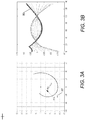
- FIG. 3A and FIG. 3B show a series of insertion sites developed for successively decreasing initial strain.
- the insertion sites are organized in two groups illustrating the posterior medial bundle and the anterior lateral bundle.
- FIG. 3A depicts PCL insertions extended from posterior medial bundle to anterolateral bundle.
- FIG. 3B depicts the strain in each fiber through the flexion arc. All of the fibers originate from a single insertion site 92, shown in FIG. 3A .
- the horizontal axis depicts an arc from 0 to 135° degrees.
- Curve 90 depicts the most posterior fiber with a strain of 4% at full extension (0° degrees flexion). The strain for the most posterior fiber increases from 4% reference strain to about 6% at 15° degrees flexion arc.
- FIG. 4A depicts sensitivity to tibial insertion site locations and FIG. 4B depicts sensitivity to lateral roll back (i.e., internal rotation).
- FIG. 4A shows the results of modifying the location of the distal insertion site locations 92 with chosen coordinates of (-25, -30), (-30, -35), (-20, -25), (-20, -25) mm. These locations 92 are arbitrarily chosen to cluster around the typical insertion site specified at (-25, -30). Distal insertions chosen within this 10 mm patch have relatively little influence on the resulting position of the near isotonic, hypotonic and hypertonic insertion sites found on the femur. The most notable change brought about by changing the distal insertion site is a change in slope of the isotonic line cluster. Also a notable extension of that line is seen in the case of extreme initial ligament laxity.
- FIG. 4B shows three cases with different lateral 'roll back' specified at 0, 8 mm, 16 mm.
- the insertion sites corresponding to each roll back case lie in line clusters arranged from left to right.
- the resulting foot print of the insertion site cluster remains a line cluster with several parallel lines representing the several 'roll back' cases. Over the explored range the patch of insertions shows moderate sensitivity to the roll back conditions.
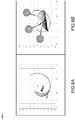
- FIG. 5A and FIG. 5B show the sensitivity to changes in the condyle geometry.
- FIG. 5A depicts sensitivity to the posterior geometry , i.e., radius change
- FIG. 5B depicts sensitivity to anterior geometry, i.e., radius change.
- FF posterior circle
- FIG. 5B depicts sensitivity to anterior geometry, i.e., radius change.
- FF posterior circle
- FIG. 5B radii of 30, 36, and 40 mm were chosen for the anterior distal circle. These radii span the extremes of radius reported by Pinskerova. In terms of the overall spread of the cluster of insertions the condylar geometry seems to have considerable influence.
- FIG. 6A depicts the sensitivity to change in transition angle
- FIG. 6B depicts adaptation path with ACL and PCL beginning at an arbitrary point A with convergence to final insertion points resulting in near isotonic fibers.
- FIG. 6A shows results for transition angles of 5°, 15°, 25°, 35°. Changes of this angle show very little impact on the insertion site cluster. It is possible that this variable would play a greater role if more extreme radii were used for the posterior and anterior circle geometries.
- FIG. 6B shows the migration of the PCL and ACL insertion sites. The initial iterates for both ACL and PCL are located at an arbitrary point A. With each iteration, the insertion site migrates toward the final near isotonic points at B and C (ACL and PCL respectively).
- FIG. 7 depicts ACL insertion sites overlaid over dissected ACL insertion foot print.
- the cluster segment labeled 1 represents the discovered ligament sites for passive knee motion
- the cluster segment labeled 2 represents anteriorly loaded knee through flexion arc.
- the adaptive migration method has been extended to include an additional feature to determine sites which will be found under conditions of joint loading rather than under solely passive flexion.
- the literature indicates that we might expect a 5 to 10 mm anterior translation of the joint under loading from the quadriceps.
- the fibers indicated by 2 are developed by displacing the tibia anteriorly by 8 mm throughout the entire flexion arc.
- ligaments are finite deformable continuous media, probably quite incompressible in nature.
- Clearly representation with discrete, infinitesimal non-interacting fibers is a rather crude approximation of the ligament element.
- modeling of such a structure through some manner of finite element means is intriguing it is beyond the scope of the current work.
- a first order geometric model could certainly be implemented which involves wrapping fibers over known geometry.
- Another approach might be to provide a flexion angle based strain representing the first order effect of the geometry of windup.
- FIG. 8 illustrates the results of inclusion of a kink model to approximate the necessity of the superficial MCL 82 to wrap around itself through the flexion arc.
- Item 84 depicts the deep MCL meniscal femoral component.
- the kink is modeled as a peg a fixed distance from the proximal insertion site about which the ligament fiber must wrap. The distance of the peg from the insertion site will be less then maximum dimension of the area of the insertion but it is not possible to formulate a better approximation without a more detailed analysis of the local material deformation.
- FIG. 9 depicts MCL insertion sites according to Robinson 72, LaPrade 74 and Fang 76.
- the representation of geometry shows great variation in the literature and none of the sources claims the images to be geometrically accurate.
- FIG. 10A shows the lateral collateral ligament (LCL) insertion sites 62 and the anterolateral ligament insertion (ALL) sites 64 as determined by adaptive migration.
- the two clusters of circles 62 represent the LCL under two conditions of anterior displacement 0 and 4 mm displacement while the circles 64 indicate the anterior lateral insertions.
- the LCL is well represented in the insertion area shown in this figure.
- the anterior lateral insertion differs from the literature reports in that it is slightly proximal to the LCL insertion rather than slightly distal. Nevertheless the ALL is said to insert at about the same place as the LCL which is the finding of the adaptive migration approach.
- FIG. 10B shows an exploration of several of the variables which may be used to shape the adaptive migration responses to external influences such as anterior tibial translation under load and lateral condylar roll back under passive motion.
- Insertion site choice might be based on a single point located at the centroid of the insertion foot print, or perhaps on multiple points on the margin of the foot print spanning the principle dimensions. But given that the model utilizes a simplified representation of the ligament elements, then constraining their insertion site to the geometry of the natural insertion site is not necessarily the best choice for the model insertion geometry. This fact is borne out by the results of the strain energy optimization approach which often leads to impossibly large strains at certain poses.
- ligaments represented by a limited number of finite fibers will not behave exactly as natural ligaments composed of continuous material but we seek to find insertion sites that will best characterize the structural and mechanical properties of the natural system. To do so we utilize our adaptive migration approach to find insertion sites that best represent the mechanical function of the system based on some simple rules and assumptions. Our goal of course is to produce a model comprised of articular surface geometry and a finite number of ligament fibers that 'optimally' represents the mechanics and kinematics of the natural (or implanted) knee.
- the adaptive migration concept provides a basis for ligament scaling around functional mechanical criteria rather than statistical methods. Coupled with other navigation and imaging techniques the adaptive migration concept adds value in promoting understanding of biomechanics and function.
- Our direct application area is in the area of implant testing. In this area it is desirable to be able to test TKR hardware in an environment that simulates the structural properties of the healthy and diseased natural knee.
- Our Vivo control system has been developed to incorporate ligament insertion site information and ligament mechanical properties as will be output by the adaptive migration process. This data is then used by the Vivo controller to create a virtual environment in which to test TKR devices.
- the adaptive migration process enables us to easily create representations of various post-surgical ligament conditions representing the spectrum of surgical outcomes.
- the adaptive migration concept also permits us to develop non-optimum models such as the effect of ligament contracture due to osseous pathologies. In fact this might be an excellent way to estimate the extent of contracture preoperatively given input from MRI or CT to quantify the degenerated osseous structure.
- the ability to mechanically represent patient pathologies will be particularly important in the area of patient specific implants.
- the adaptive migration concept has direct application to ligament reconstructive surgery as the ideal insertion sites for the replacement ligament material or graft can be determined based on the patient's joint geometry. Reconstruction of the ACL is one of the most frequent orthopedic procedures in the US today. MCL reconstruction is also quite frequent while PCL reconstruction is gaining frequency. In all of these cases the adaptive migration methodology lends insights into optimum location for replacing ligament material.
- the adaptive migration concept is applicable to all of the joints of the human body and can also be used in veterinary reconstructive surgery applications.
Landscapes
- Health & Medical Sciences (AREA)
- Life Sciences & Earth Sciences (AREA)
- Surgery (AREA)
- Engineering & Computer Science (AREA)
- Medical Informatics (AREA)
- Animal Behavior & Ethology (AREA)
- Veterinary Medicine (AREA)
- Public Health (AREA)
- General Health & Medical Sciences (AREA)
- Molecular Biology (AREA)
- Biomedical Technology (AREA)
- Heart & Thoracic Surgery (AREA)
- Physics & Mathematics (AREA)
- Dentistry (AREA)
- Oral & Maxillofacial Surgery (AREA)
- Orthopedic Medicine & Surgery (AREA)
- Pathology (AREA)
- Biophysics (AREA)
- Rheumatology (AREA)
- Nuclear Medicine, Radiotherapy & Molecular Imaging (AREA)
- Physiology (AREA)
- Geometry (AREA)
- Rehabilitation Therapy (AREA)
- Physical Education & Sports Medicine (AREA)
- Robotics (AREA)
- Prostheses (AREA)
- Surgical Instruments (AREA)
Applications Claiming Priority (3)
| Application Number | Priority Date | Filing Date | Title |
|---|---|---|---|
| US201461955446P | 2014-03-19 | 2014-03-19 | |
| US14/661,190 US9629580B2 (en) | 2014-03-19 | 2015-03-18 | System and method for ligament insertion in knee joint surgeries using adaptive migration of ligament insertion geometry |
| PCT/US2015/021429 WO2015143131A1 (en) | 2014-03-19 | 2015-03-19 | System and method for ligament insertion in knee joint surgeries using adaptive migration of ligament insertion geometry |
Publications (3)
| Publication Number | Publication Date |
|---|---|
| EP3120275A1 EP3120275A1 (en) | 2017-01-25 |
| EP3120275A4 EP3120275A4 (en) | 2017-12-27 |
| EP3120275B1 true EP3120275B1 (en) | 2020-08-26 |
Family
ID=54140978
Family Applications (1)
| Application Number | Title | Priority Date | Filing Date |
|---|---|---|---|
| EP15765035.9A Active EP3120275B1 (en) | 2014-03-19 | 2015-03-19 | System for ligament insertion in knee joint surgeries using adaptive migration of ligament insertion geometry |
Country Status (9)
| Country | Link |
|---|---|
| US (2) | US9629580B2 (https=) |
| EP (1) | EP3120275B1 (https=) |
| JP (1) | JP6532934B2 (https=) |
| KR (1) | KR101844706B1 (https=) |
| CN (1) | CN106462659B (https=) |
| AU (1) | AU2015231264B2 (https=) |
| CA (1) | CA2944945C (https=) |
| DK (1) | DK3120275T3 (https=) |
| WO (1) | WO2015143131A1 (https=) |
Families Citing this family (7)
| Publication number | Priority date | Publication date | Assignee | Title |
|---|---|---|---|---|
| EP2849683A4 (en) | 2012-05-18 | 2015-11-25 | Orthalign Inc | DEVICES AND METHODS FOR KNEE HIPPLASTY |
| US9629580B2 (en) * | 2014-03-19 | 2017-04-25 | Advanced Mechanical Technology, Inc. | System and method for ligament insertion in knee joint surgeries using adaptive migration of ligament insertion geometry |
| AU2016371923B2 (en) * | 2015-12-17 | 2019-05-09 | Materialise N.V. | Pre-operative determination of implant configuration for soft-tissue balancing in orthopedic surgery |
| WO2018169980A1 (en) | 2017-03-14 | 2018-09-20 | OrthAlign, Inc. | Soft tissue measurement & balancing systems and methods |
| CN110418619B (zh) * | 2017-03-14 | 2023-11-03 | 史密夫和内修有限公司 | 用于测量骨关节松驰度的系统和方法 |
| CN108056846A (zh) * | 2018-01-05 | 2018-05-22 | 石波 | 一种胫骨基座、解剖型膝关节假体及模具 |
| FR3148899A1 (fr) * | 2023-05-24 | 2024-11-29 | Twinsight | Procédé de détermination de paramètres de pose d’une prothèse sur une articulation d’un patient |
Family Cites Families (20)
| Publication number | Priority date | Publication date | Assignee | Title |
|---|---|---|---|---|
| US5014719A (en) | 1984-02-02 | 1991-05-14 | Mcleod Paul C | Knee loading and testing apparatus and method |
| US8556983B2 (en) | 2001-05-25 | 2013-10-15 | Conformis, Inc. | Patient-adapted and improved orthopedic implants, designs and related tools |
| US8480754B2 (en) | 2001-05-25 | 2013-07-09 | Conformis, Inc. | Patient-adapted and improved articular implants, designs and related guide tools |
| US6161080A (en) | 1997-11-17 | 2000-12-12 | The Trustees Of Columbia University In The City Of New York | Three dimensional multibody modeling of anatomical joints |
| DE10130485C2 (de) | 2001-06-25 | 2003-06-26 | Robert Riener | Programmierbarer Gelenksimulator |
| US20050119661A1 (en) | 2001-11-14 | 2005-06-02 | Hodgson Antony J. | Methods and systems for intraoperative measurement of soft tissue constraints in computer aided total joint replacement surgery |
| US20030153978A1 (en) | 2002-02-08 | 2003-08-14 | Whiteside Biomechanics, Inc. | Apparatus and method of ligament balancing and component fit check in total knee arthroplasty |
| AU2003228341A1 (en) | 2002-03-19 | 2003-10-08 | The Board Of Trustees Of The University Of Illinois | System and method for prosthetic fitting and balancing in joints |
| AU2002338818A1 (en) | 2002-09-27 | 2004-05-04 | Aesculap Ag And Co. Kg | Method and device for determining the position of the tibial protrusion point of the anterior cruciate ligament |
| AU2005209197A1 (en) * | 2004-01-16 | 2005-08-11 | Smith & Nephew, Inc. | Computer-assisted ligament balancing in total knee arthroplasty |
| US20060161052A1 (en) | 2004-12-08 | 2006-07-20 | Perception Raisonnement Action En Medecine | Computer assisted orthopaedic surgery system for ligament graft reconstruction |
| US7823460B2 (en) | 2005-08-12 | 2010-11-02 | Advanced Mechanical Technology, Inc. | Prosthetic simulator with soft tissue modeling |
| CA2734293C (en) | 2008-08-20 | 2017-01-10 | Synvasive Technology, Inc. | Sensing force during partial and total knee replacement surgery |
| FR2936949A1 (fr) * | 2008-10-09 | 2010-04-16 | Amplitude | Systeme de modelisation et d'assistance pour la reconstruction d'un ligament croise anterieur |
| SG175229A1 (en) | 2009-04-16 | 2011-11-28 | Conformis Inc | Patient-specific joint arthroplasty devices for ligament repair |
| EP2429408A1 (en) | 2009-05-14 | 2012-03-21 | Blue Ortho | Device and method of automatic calibration of a tensor in arthroplasty procedures |
| CA2779013C (en) | 2009-11-09 | 2018-03-13 | Advanced Mechanical Technology, Inc. | System and method for joint motion simulation |
| US9521965B2 (en) | 2011-08-09 | 2016-12-20 | The Regents Of The University Of California | Mechanical pivot shift measurement to evaluate joints |
| CN103565438B (zh) * | 2012-08-06 | 2016-03-02 | 纳通生物科技(北京)有限公司 | 韧带平衡调节辅助装置及其膝关节弯曲与外旋角度计算方法 |
| US9629580B2 (en) * | 2014-03-19 | 2017-04-25 | Advanced Mechanical Technology, Inc. | System and method for ligament insertion in knee joint surgeries using adaptive migration of ligament insertion geometry |
-
2015
- 2015-03-18 US US14/661,190 patent/US9629580B2/en active Active
- 2015-03-19 KR KR1020167029138A patent/KR101844706B1/ko active Active
- 2015-03-19 CN CN201580023992.2A patent/CN106462659B/zh active Active
- 2015-03-19 EP EP15765035.9A patent/EP3120275B1/en active Active
- 2015-03-19 JP JP2017501109A patent/JP6532934B2/ja active Active
- 2015-03-19 DK DK15765035.9T patent/DK3120275T3/da active
- 2015-03-19 AU AU2015231264A patent/AU2015231264B2/en active Active
- 2015-03-19 WO PCT/US2015/021429 patent/WO2015143131A1/en not_active Ceased
- 2015-03-19 CA CA2944945A patent/CA2944945C/en active Active
-
2017
- 2017-03-16 US US15/460,494 patent/US9788781B2/en active Active
Non-Patent Citations (1)
| Title |
|---|
| None * |
Also Published As
| Publication number | Publication date |
|---|---|
| AU2015231264B2 (en) | 2020-07-02 |
| AU2015231264A1 (en) | 2016-10-13 |
| US20150265363A1 (en) | 2015-09-24 |
| JP6532934B2 (ja) | 2019-06-19 |
| EP3120275A4 (en) | 2017-12-27 |
| CN106462659B (zh) | 2019-11-08 |
| US9629580B2 (en) | 2017-04-25 |
| EP3120275A1 (en) | 2017-01-25 |
| US20170258394A1 (en) | 2017-09-14 |
| WO2015143131A1 (en) | 2015-09-24 |
| CA2944945A1 (en) | 2015-09-24 |
| US9788781B2 (en) | 2017-10-17 |
| CN106462659A (zh) | 2017-02-22 |
| DK3120275T3 (da) | 2020-11-30 |
| KR101844706B1 (ko) | 2018-04-02 |
| KR20160135782A (ko) | 2016-11-28 |
| CA2944945C (en) | 2022-05-24 |
| JP2017512616A (ja) | 2017-05-25 |
Similar Documents
| Publication | Publication Date | Title |
|---|---|---|
| US9788781B2 (en) | System and method for ligament insertion in knee joint surgeries using adaptive migration of ligament insertion geometry | |
| Kang et al. | Influence of increased posterior tibial slope in total knee arthroplasty on knee joint biomechanics: a computational simulation study | |
| US10789858B2 (en) | Method for creating a computer model of a joint for treatment planning | |
| Kowalczewski et al. | Does joint line elevation after revision knee arthroplasty affect tibio-femoral kinematics, contact pressure or collateral ligament lengths? An in vitro analysis | |
| Walker et al. | Characterizing the motion of total knee replacements in laboratory tests. | |
| Viceconti et al. | Pre‐operative prediction of soft tissue balancing in knee arthoplasty part 1: effect of surgical parameters during level walking | |
| Amiri et al. | Mechanics of the passive knee joint. Part 1: the role of the tibial articular surfaces in guiding the passive motion | |
| Wang et al. | Load sharing among collateral ligaments, articular surfaces, and the tibial post in constrained condylar knee arthroplasty | |
| Akalan et al. | Three-dimensional knee model: Constrained by isometric ligament bundles and experimentally obtained tibio-femoral contacts | |
| US20240315603A1 (en) | Patient Morphology-Driven Knee Kinematics | |
| Lenz et al. | The effects of femoral fixed body coordinate system definition on knee kinematic description | |
| Imran | Sagittal plane knee laxity after ligament retaining unconstrained arthroplasty: a mathematical analysis | |
| Liu et al. | Anatomic-like polyethylene insert could improve knee kinematics after total knee arthroplasty—a computational assessment | |
| Tarniţă et al. | The virtual model of the prosthetic tibial components | |
| Roth | How well does kinematically aligned total knee arthroplasty prevent clinically important changes in passive knee function? An in vitro biomechanical study of tibiofemoral laxities and contact | |
| Hast et al. | Position of the quadriceps actuator influences knee loads during simulated squat testing | |
| Trad et al. | Finite element models of the knee joint | |
| Bowen | A Quantitative Analysis of the Unified Envelope Prediction, with Improved Data Collection Tools | |
| Anantha Krishnan | Computational Methodology for Generating Patient-Specific Soft Tissue Representations | |
| Imran | Knee laxity after unicompartmental joint replacement: A planar mathematical analysis | |
| Putame | Development of Computational Multibody Models of Anatomical and Prosthetic Knee Joints as Evaluation Tool for Orthopaedic Interventions and Prosthesis Design | |
| Sundaraj et al. | Towards a complete intra-operative CT-free navigation system for anterior cruciate ligament reconstruction | |
| Nardini | Subject Specific Knee Joint Modelling Based on In Vivo Clinical Data | |
| Mane | Combined Experimental and Statistical Model to Understand the Role of Anatomical and Implant Alignment Variables in Guiding Knee Joint Motion | |
| Sundaraj et al. | Towards a Complete Intra-Operative CT-Free Navigation System for Arthroscopy Anterior Cruciate Ligament Reconstruction |
Legal Events
| Date | Code | Title | Description |
|---|---|---|---|
| STAA | Information on the status of an ep patent application or granted ep patent |
Free format text: STATUS: THE INTERNATIONAL PUBLICATION HAS BEEN MADE |
|
| PUAI | Public reference made under article 153(3) epc to a published international application that has entered the european phase |
Free format text: ORIGINAL CODE: 0009012 |
|
| STAA | Information on the status of an ep patent application or granted ep patent |
Free format text: STATUS: REQUEST FOR EXAMINATION WAS MADE |
|
| 17P | Request for examination filed |
Effective date: 20161014 |
|
| AK | Designated contracting states |
Kind code of ref document: A1 Designated state(s): AL AT BE BG CH CY CZ DE DK EE ES FI FR GB GR HR HU IE IS IT LI LT LU LV MC MK MT NL NO PL PT RO RS SE SI SK SM TR |
|
| AX | Request for extension of the european patent |
Extension state: BA ME |
|
| DAV | Request for validation of the european patent (deleted) | ||
| DAX | Request for extension of the european patent (deleted) | ||
| A4 | Supplementary search report drawn up and despatched |
Effective date: 20171123 |
|
| RIC1 | Information provided on ipc code assigned before grant |
Ipc: A61B 5/11 20060101ALN20171117BHEP Ipc: A61B 17/17 20060101ALN20171117BHEP Ipc: A61B 34/10 20160101AFI20171117BHEP |
|
| GRAP | Despatch of communication of intention to grant a patent |
Free format text: ORIGINAL CODE: EPIDOSNIGR1 |
|
| STAA | Information on the status of an ep patent application or granted ep patent |
Free format text: STATUS: GRANT OF PATENT IS INTENDED |
|
| RIC1 | Information provided on ipc code assigned before grant |
Ipc: A61B 34/10 20160101AFI20200220BHEP Ipc: A61B 17/17 20060101ALN20200220BHEP Ipc: A61B 5/11 20060101ALN20200220BHEP |
|
| INTG | Intention to grant announced |
Effective date: 20200316 |
|
| GRAJ | Information related to disapproval of communication of intention to grant by the applicant or resumption of examination proceedings by the epo deleted |
Free format text: ORIGINAL CODE: EPIDOSDIGR1 |
|
| STAA | Information on the status of an ep patent application or granted ep patent |
Free format text: STATUS: REQUEST FOR EXAMINATION WAS MADE |
|
| REG | Reference to a national code |
Ref country code: DE Ref legal event code: R079 Ref document number: 602015058034 Country of ref document: DE Free format text: PREVIOUS MAIN CLASS: G06F0019000000 Ipc: A61B0034100000 |
|
| GRAR | Information related to intention to grant a patent recorded |
Free format text: ORIGINAL CODE: EPIDOSNIGR71 |
|
| GRAS | Grant fee paid |
Free format text: ORIGINAL CODE: EPIDOSNIGR3 |
|
| STAA | Information on the status of an ep patent application or granted ep patent |
Free format text: STATUS: GRANT OF PATENT IS INTENDED |
|
| GRAA | (expected) grant |
Free format text: ORIGINAL CODE: 0009210 |
|
| STAA | Information on the status of an ep patent application or granted ep patent |
Free format text: STATUS: THE PATENT HAS BEEN GRANTED |
|
| INTC | Intention to grant announced (deleted) | ||
| RIC1 | Information provided on ipc code assigned before grant |
Ipc: A61B 34/10 20160101AFI20200709BHEP Ipc: A61B 17/17 20060101ALN20200709BHEP Ipc: A61B 5/11 20060101ALN20200709BHEP |
|
| INTG | Intention to grant announced |
Effective date: 20200716 |
|
| AK | Designated contracting states |
Kind code of ref document: B1 Designated state(s): AL AT BE BG CH CY CZ DE DK EE ES FI FR GB GR HR HU IE IS IT LI LT LU LV MC MK MT NL NO PL PT RO RS SE SI SK SM TR |
|
| REG | Reference to a national code |
Ref country code: GB Ref legal event code: FG4D |
|
| REG | Reference to a national code |
Ref country code: CH Ref legal event code: EP |
|
| REG | Reference to a national code |
Ref country code: AT Ref legal event code: REF Ref document number: 1305617 Country of ref document: AT Kind code of ref document: T Effective date: 20200915 |
|
| REG | Reference to a national code |
Ref country code: IE Ref legal event code: FG4D |
|
| REG | Reference to a national code |
Ref country code: DE Ref legal event code: R096 Ref document number: 602015058034 Country of ref document: DE |
|
| REG | Reference to a national code |
Ref country code: CH Ref legal event code: NV Representative=s name: PINTZ AND PARTNERS LLC, CH Ref country code: DK Ref legal event code: T3 Effective date: 20201125 |
|
| REG | Reference to a national code |
Ref country code: NL Ref legal event code: FP |
|
| REG | Reference to a national code |
Ref country code: SE Ref legal event code: TRGR |
|
| REG | Reference to a national code |
Ref country code: LT Ref legal event code: MG4D |
|
| PG25 | Lapsed in a contracting state [announced via postgrant information from national office to epo] |
Ref country code: NO Free format text: LAPSE BECAUSE OF FAILURE TO SUBMIT A TRANSLATION OF THE DESCRIPTION OR TO PAY THE FEE WITHIN THE PRESCRIBED TIME-LIMIT Effective date: 20201126 Ref country code: BG Free format text: LAPSE BECAUSE OF FAILURE TO SUBMIT A TRANSLATION OF THE DESCRIPTION OR TO PAY THE FEE WITHIN THE PRESCRIBED TIME-LIMIT Effective date: 20201126 Ref country code: FI Free format text: LAPSE BECAUSE OF FAILURE TO SUBMIT A TRANSLATION OF THE DESCRIPTION OR TO PAY THE FEE WITHIN THE PRESCRIBED TIME-LIMIT Effective date: 20200826 Ref country code: GR Free format text: LAPSE BECAUSE OF FAILURE TO SUBMIT A TRANSLATION OF THE DESCRIPTION OR TO PAY THE FEE WITHIN THE PRESCRIBED TIME-LIMIT Effective date: 20201127 Ref country code: LT Free format text: LAPSE BECAUSE OF FAILURE TO SUBMIT A TRANSLATION OF THE DESCRIPTION OR TO PAY THE FEE WITHIN THE PRESCRIBED TIME-LIMIT Effective date: 20200826 Ref country code: HR Free format text: LAPSE BECAUSE OF FAILURE TO SUBMIT A TRANSLATION OF THE DESCRIPTION OR TO PAY THE FEE WITHIN THE PRESCRIBED TIME-LIMIT Effective date: 20200826 Ref country code: PT Free format text: LAPSE BECAUSE OF FAILURE TO SUBMIT A TRANSLATION OF THE DESCRIPTION OR TO PAY THE FEE WITHIN THE PRESCRIBED TIME-LIMIT Effective date: 20201228 |
|
| REG | Reference to a national code |
Ref country code: AT Ref legal event code: MK05 Ref document number: 1305617 Country of ref document: AT Kind code of ref document: T Effective date: 20200826 |
|
| PG25 | Lapsed in a contracting state [announced via postgrant information from national office to epo] |
Ref country code: LV Free format text: LAPSE BECAUSE OF FAILURE TO SUBMIT A TRANSLATION OF THE DESCRIPTION OR TO PAY THE FEE WITHIN THE PRESCRIBED TIME-LIMIT Effective date: 20200826 Ref country code: RS Free format text: LAPSE BECAUSE OF FAILURE TO SUBMIT A TRANSLATION OF THE DESCRIPTION OR TO PAY THE FEE WITHIN THE PRESCRIBED TIME-LIMIT Effective date: 20200826 Ref country code: IS Free format text: LAPSE BECAUSE OF FAILURE TO SUBMIT A TRANSLATION OF THE DESCRIPTION OR TO PAY THE FEE WITHIN THE PRESCRIBED TIME-LIMIT Effective date: 20201226 |
|
| PG25 | Lapsed in a contracting state [announced via postgrant information from national office to epo] |
Ref country code: CZ Free format text: LAPSE BECAUSE OF FAILURE TO SUBMIT A TRANSLATION OF THE DESCRIPTION OR TO PAY THE FEE WITHIN THE PRESCRIBED TIME-LIMIT Effective date: 20200826 Ref country code: EE Free format text: LAPSE BECAUSE OF FAILURE TO SUBMIT A TRANSLATION OF THE DESCRIPTION OR TO PAY THE FEE WITHIN THE PRESCRIBED TIME-LIMIT Effective date: 20200826 Ref country code: SM Free format text: LAPSE BECAUSE OF FAILURE TO SUBMIT A TRANSLATION OF THE DESCRIPTION OR TO PAY THE FEE WITHIN THE PRESCRIBED TIME-LIMIT Effective date: 20200826 Ref country code: RO Free format text: LAPSE BECAUSE OF FAILURE TO SUBMIT A TRANSLATION OF THE DESCRIPTION OR TO PAY THE FEE WITHIN THE PRESCRIBED TIME-LIMIT Effective date: 20200826 |
|
| REG | Reference to a national code |
Ref country code: DE Ref legal event code: R097 Ref document number: 602015058034 Country of ref document: DE |
|
| PG25 | Lapsed in a contracting state [announced via postgrant information from national office to epo] |
Ref country code: ES Free format text: LAPSE BECAUSE OF FAILURE TO SUBMIT A TRANSLATION OF THE DESCRIPTION OR TO PAY THE FEE WITHIN THE PRESCRIBED TIME-LIMIT Effective date: 20200826 Ref country code: AL Free format text: LAPSE BECAUSE OF FAILURE TO SUBMIT A TRANSLATION OF THE DESCRIPTION OR TO PAY THE FEE WITHIN THE PRESCRIBED TIME-LIMIT Effective date: 20200826 Ref country code: AT Free format text: LAPSE BECAUSE OF FAILURE TO SUBMIT A TRANSLATION OF THE DESCRIPTION OR TO PAY THE FEE WITHIN THE PRESCRIBED TIME-LIMIT Effective date: 20200826 |
|
| PG25 | Lapsed in a contracting state [announced via postgrant information from national office to epo] |
Ref country code: SK Free format text: LAPSE BECAUSE OF FAILURE TO SUBMIT A TRANSLATION OF THE DESCRIPTION OR TO PAY THE FEE WITHIN THE PRESCRIBED TIME-LIMIT Effective date: 20200826 |
|
| PLBE | No opposition filed within time limit |
Free format text: ORIGINAL CODE: 0009261 |
|
| STAA | Information on the status of an ep patent application or granted ep patent |
Free format text: STATUS: NO OPPOSITION FILED WITHIN TIME LIMIT |
|
| PG25 | Lapsed in a contracting state [announced via postgrant information from national office to epo] |
Ref country code: IT Free format text: LAPSE BECAUSE OF FAILURE TO SUBMIT A TRANSLATION OF THE DESCRIPTION OR TO PAY THE FEE WITHIN THE PRESCRIBED TIME-LIMIT Effective date: 20200826 |
|
| 26N | No opposition filed |
Effective date: 20210527 |
|
| PG25 | Lapsed in a contracting state [announced via postgrant information from national office to epo] |
Ref country code: SI Free format text: LAPSE BECAUSE OF FAILURE TO SUBMIT A TRANSLATION OF THE DESCRIPTION OR TO PAY THE FEE WITHIN THE PRESCRIBED TIME-LIMIT Effective date: 20200826 |
|
| PG25 | Lapsed in a contracting state [announced via postgrant information from national office to epo] |
Ref country code: MC Free format text: LAPSE BECAUSE OF FAILURE TO SUBMIT A TRANSLATION OF THE DESCRIPTION OR TO PAY THE FEE WITHIN THE PRESCRIBED TIME-LIMIT Effective date: 20200826 |
|
| PG25 | Lapsed in a contracting state [announced via postgrant information from national office to epo] |
Ref country code: LU Free format text: LAPSE BECAUSE OF NON-PAYMENT OF DUE FEES Effective date: 20210319 |
|
| PG25 | Lapsed in a contracting state [announced via postgrant information from national office to epo] |
Ref country code: HU Free format text: LAPSE BECAUSE OF FAILURE TO SUBMIT A TRANSLATION OF THE DESCRIPTION OR TO PAY THE FEE WITHIN THE PRESCRIBED TIME-LIMIT; INVALID AB INITIO Effective date: 20150319 |
|
| PG25 | Lapsed in a contracting state [announced via postgrant information from national office to epo] |
Ref country code: CY Free format text: LAPSE BECAUSE OF FAILURE TO SUBMIT A TRANSLATION OF THE DESCRIPTION OR TO PAY THE FEE WITHIN THE PRESCRIBED TIME-LIMIT Effective date: 20200826 |
|
| PG25 | Lapsed in a contracting state [announced via postgrant information from national office to epo] |
Ref country code: MK Free format text: LAPSE BECAUSE OF FAILURE TO SUBMIT A TRANSLATION OF THE DESCRIPTION OR TO PAY THE FEE WITHIN THE PRESCRIBED TIME-LIMIT Effective date: 20200826 |
|
| PG25 | Lapsed in a contracting state [announced via postgrant information from national office to epo] |
Ref country code: TR Free format text: LAPSE BECAUSE OF FAILURE TO SUBMIT A TRANSLATION OF THE DESCRIPTION OR TO PAY THE FEE WITHIN THE PRESCRIBED TIME-LIMIT Effective date: 20200826 |
|
| PG25 | Lapsed in a contracting state [announced via postgrant information from national office to epo] |
Ref country code: MT Free format text: LAPSE BECAUSE OF FAILURE TO SUBMIT A TRANSLATION OF THE DESCRIPTION OR TO PAY THE FEE WITHIN THE PRESCRIBED TIME-LIMIT Effective date: 20200826 |
|
| PGFP | Annual fee paid to national office [announced via postgrant information from national office to epo] |
Ref country code: PL Payment date: 20250422 Year of fee payment: 11 |
|
| PGFP | Annual fee paid to national office [announced via postgrant information from national office to epo] |
Ref country code: CH Payment date: 20250522 Year of fee payment: 11 |
|
| REG | Reference to a national code |
Ref country code: CH Ref legal event code: R18 Free format text: ST27 STATUS EVENT CODE: U-0-0-R10-R18 (AS PROVIDED BY THE NATIONAL OFFICE) Effective date: 20260331 |
|
| REG | Reference to a national code |
Ref country code: CH Ref legal event code: U11 Free format text: ST27 STATUS EVENT CODE: U-0-0-U10-U11 (AS PROVIDED BY THE NATIONAL OFFICE) Effective date: 20260401 |
|
| PGFP | Annual fee paid to national office [announced via postgrant information from national office to epo] |
Ref country code: SE Payment date: 20260323 Year of fee payment: 12 |
|
| PGFP | Annual fee paid to national office [announced via postgrant information from national office to epo] |
Ref country code: GB Payment date: 20260226 Year of fee payment: 12 |
|
| PGFP | Annual fee paid to national office [announced via postgrant information from national office to epo] |
Ref country code: DE Payment date: 20260227 Year of fee payment: 12 Ref country code: DK Payment date: 20260323 Year of fee payment: 12 Ref country code: IE Payment date: 20260226 Year of fee payment: 12 |
|
| PGFP | Annual fee paid to national office [announced via postgrant information from national office to epo] |
Ref country code: BE Payment date: 20260227 Year of fee payment: 12 |
|
| PGFP | Annual fee paid to national office [announced via postgrant information from national office to epo] |
Ref country code: NL Payment date: 20260227 Year of fee payment: 12 |
|
| PGFP | Annual fee paid to national office [announced via postgrant information from national office to epo] |
Ref country code: FR Payment date: 20260226 Year of fee payment: 12 |