EP3119626B1 - Method for controlling a hybrid driveline - Google Patents
Method for controlling a hybrid driveline Download PDFInfo
- Publication number
- EP3119626B1 EP3119626B1 EP15764140.8A EP15764140A EP3119626B1 EP 3119626 B1 EP3119626 B1 EP 3119626B1 EP 15764140 A EP15764140 A EP 15764140A EP 3119626 B1 EP3119626 B1 EP 3119626B1
- Authority
- EP
- European Patent Office
- Prior art keywords
- gear
- planetary gear
- planetary
- electrical machine
- torque
- Prior art date
- Legal status (The legal status is an assumption and is not a legal conclusion. Google has not performed a legal analysis and makes no representation as to the accuracy of the status listed.)
- Active
Links
- 238000000034 method Methods 0.000 title claims description 34
- 230000008878 coupling Effects 0.000 claims description 128
- 238000010168 coupling process Methods 0.000 claims description 128
- 238000005859 coupling reaction Methods 0.000 claims description 128
- 238000002485 combustion reaction Methods 0.000 claims description 82
- 238000004590 computer program Methods 0.000 claims description 12
- FGUUSXIOTUKUDN-IBGZPJMESA-N C1(=CC=CC=C1)N1C2=C(NC([C@H](C1)NC=1OC(=NN=1)C1=CC=CC=C1)=O)C=CC=C2 Chemical compound C1(=CC=CC=C1)N1C2=C(NC([C@H](C1)NC=1OC(=NN=1)C1=CC=CC=C1)=O)C=CC=C2 FGUUSXIOTUKUDN-IBGZPJMESA-N 0.000 claims description 2
- 238000004146 energy storage Methods 0.000 description 53
- 230000001360 synchronised effect Effects 0.000 description 25
- 230000005540 biological transmission Effects 0.000 description 21
- 230000007246 mechanism Effects 0.000 description 19
- 238000002347 injection Methods 0.000 description 6
- 239000007924 injection Substances 0.000 description 6
- 238000010276 construction Methods 0.000 description 5
- 230000006870 function Effects 0.000 description 5
- 239000000969 carrier Substances 0.000 description 4
- 230000001172 regenerating effect Effects 0.000 description 4
- 238000006243 chemical reaction Methods 0.000 description 3
- 238000004519 manufacturing process Methods 0.000 description 3
- 230000007704 transition Effects 0.000 description 3
- 230000007423 decrease Effects 0.000 description 2
- 239000000446 fuel Substances 0.000 description 2
- 230000009347 mechanical transmission Effects 0.000 description 2
- 230000008569 process Effects 0.000 description 2
- 239000000243 solution Substances 0.000 description 2
- 230000001133 acceleration Effects 0.000 description 1
- 230000003213 activating effect Effects 0.000 description 1
- 230000008901 benefit Effects 0.000 description 1
- 230000008859 change Effects 0.000 description 1
- 230000001419 dependent effect Effects 0.000 description 1
- 230000000694 effects Effects 0.000 description 1
- 238000012983 electrochemical energy storage Methods 0.000 description 1
- 239000000284 extract Substances 0.000 description 1
- 238000000605 extraction Methods 0.000 description 1
- 238000010438 heat treatment Methods 0.000 description 1
- 230000003116 impacting effect Effects 0.000 description 1
- 230000008439 repair process Effects 0.000 description 1
Images

Classifications
-
- B—PERFORMING OPERATIONS; TRANSPORTING
- B60—VEHICLES IN GENERAL
- B60K—ARRANGEMENT OR MOUNTING OF PROPULSION UNITS OR OF TRANSMISSIONS IN VEHICLES; ARRANGEMENT OR MOUNTING OF PLURAL DIVERSE PRIME-MOVERS IN VEHICLES; AUXILIARY DRIVES FOR VEHICLES; INSTRUMENTATION OR DASHBOARDS FOR VEHICLES; ARRANGEMENTS IN CONNECTION WITH COOLING, AIR INTAKE, GAS EXHAUST OR FUEL SUPPLY OF PROPULSION UNITS IN VEHICLES
- B60K6/00—Arrangement or mounting of plural diverse prime-movers for mutual or common propulsion, e.g. hybrid propulsion systems comprising electric motors and internal combustion engines ; Control systems therefor, i.e. systems controlling two or more prime movers, or controlling one of these prime movers and any of the transmission, drive or drive units Informative references: mechanical gearings with secondary electric drive F16H3/72; arrangements for handling mechanical energy structurally associated with the dynamo-electric machine H02K7/00; machines comprising structurally interrelated motor and generator parts H02K51/00; dynamo-electric machines not otherwise provided for in H02K see H02K99/00
- B60K6/20—Arrangement or mounting of plural diverse prime-movers for mutual or common propulsion, e.g. hybrid propulsion systems comprising electric motors and internal combustion engines ; Control systems therefor, i.e. systems controlling two or more prime movers, or controlling one of these prime movers and any of the transmission, drive or drive units Informative references: mechanical gearings with secondary electric drive F16H3/72; arrangements for handling mechanical energy structurally associated with the dynamo-electric machine H02K7/00; machines comprising structurally interrelated motor and generator parts H02K51/00; dynamo-electric machines not otherwise provided for in H02K see H02K99/00 the prime-movers consisting of electric motors and internal combustion engines, e.g. HEVs
- B60K6/22—Arrangement or mounting of plural diverse prime-movers for mutual or common propulsion, e.g. hybrid propulsion systems comprising electric motors and internal combustion engines ; Control systems therefor, i.e. systems controlling two or more prime movers, or controlling one of these prime movers and any of the transmission, drive or drive units Informative references: mechanical gearings with secondary electric drive F16H3/72; arrangements for handling mechanical energy structurally associated with the dynamo-electric machine H02K7/00; machines comprising structurally interrelated motor and generator parts H02K51/00; dynamo-electric machines not otherwise provided for in H02K see H02K99/00 the prime-movers consisting of electric motors and internal combustion engines, e.g. HEVs characterised by apparatus, components or means specially adapted for HEVs
- B60K6/36—Arrangement or mounting of plural diverse prime-movers for mutual or common propulsion, e.g. hybrid propulsion systems comprising electric motors and internal combustion engines ; Control systems therefor, i.e. systems controlling two or more prime movers, or controlling one of these prime movers and any of the transmission, drive or drive units Informative references: mechanical gearings with secondary electric drive F16H3/72; arrangements for handling mechanical energy structurally associated with the dynamo-electric machine H02K7/00; machines comprising structurally interrelated motor and generator parts H02K51/00; dynamo-electric machines not otherwise provided for in H02K see H02K99/00 the prime-movers consisting of electric motors and internal combustion engines, e.g. HEVs characterised by apparatus, components or means specially adapted for HEVs characterised by the transmission gearings
- B60K6/365—Arrangement or mounting of plural diverse prime-movers for mutual or common propulsion, e.g. hybrid propulsion systems comprising electric motors and internal combustion engines ; Control systems therefor, i.e. systems controlling two or more prime movers, or controlling one of these prime movers and any of the transmission, drive or drive units Informative references: mechanical gearings with secondary electric drive F16H3/72; arrangements for handling mechanical energy structurally associated with the dynamo-electric machine H02K7/00; machines comprising structurally interrelated motor and generator parts H02K51/00; dynamo-electric machines not otherwise provided for in H02K see H02K99/00 the prime-movers consisting of electric motors and internal combustion engines, e.g. HEVs characterised by apparatus, components or means specially adapted for HEVs characterised by the transmission gearings with the gears having orbital motion
-
- B—PERFORMING OPERATIONS; TRANSPORTING
- B60—VEHICLES IN GENERAL
- B60K—ARRANGEMENT OR MOUNTING OF PROPULSION UNITS OR OF TRANSMISSIONS IN VEHICLES; ARRANGEMENT OR MOUNTING OF PLURAL DIVERSE PRIME-MOVERS IN VEHICLES; AUXILIARY DRIVES FOR VEHICLES; INSTRUMENTATION OR DASHBOARDS FOR VEHICLES; ARRANGEMENTS IN CONNECTION WITH COOLING, AIR INTAKE, GAS EXHAUST OR FUEL SUPPLY OF PROPULSION UNITS IN VEHICLES
- B60K1/00—Arrangement or mounting of electrical propulsion units
- B60K1/02—Arrangement or mounting of electrical propulsion units comprising more than one electric motor
-
- B—PERFORMING OPERATIONS; TRANSPORTING
- B60—VEHICLES IN GENERAL
- B60K—ARRANGEMENT OR MOUNTING OF PROPULSION UNITS OR OF TRANSMISSIONS IN VEHICLES; ARRANGEMENT OR MOUNTING OF PLURAL DIVERSE PRIME-MOVERS IN VEHICLES; AUXILIARY DRIVES FOR VEHICLES; INSTRUMENTATION OR DASHBOARDS FOR VEHICLES; ARRANGEMENTS IN CONNECTION WITH COOLING, AIR INTAKE, GAS EXHAUST OR FUEL SUPPLY OF PROPULSION UNITS IN VEHICLES
- B60K6/00—Arrangement or mounting of plural diverse prime-movers for mutual or common propulsion, e.g. hybrid propulsion systems comprising electric motors and internal combustion engines ; Control systems therefor, i.e. systems controlling two or more prime movers, or controlling one of these prime movers and any of the transmission, drive or drive units Informative references: mechanical gearings with secondary electric drive F16H3/72; arrangements for handling mechanical energy structurally associated with the dynamo-electric machine H02K7/00; machines comprising structurally interrelated motor and generator parts H02K51/00; dynamo-electric machines not otherwise provided for in H02K see H02K99/00
- B60K6/20—Arrangement or mounting of plural diverse prime-movers for mutual or common propulsion, e.g. hybrid propulsion systems comprising electric motors and internal combustion engines ; Control systems therefor, i.e. systems controlling two or more prime movers, or controlling one of these prime movers and any of the transmission, drive or drive units Informative references: mechanical gearings with secondary electric drive F16H3/72; arrangements for handling mechanical energy structurally associated with the dynamo-electric machine H02K7/00; machines comprising structurally interrelated motor and generator parts H02K51/00; dynamo-electric machines not otherwise provided for in H02K see H02K99/00 the prime-movers consisting of electric motors and internal combustion engines, e.g. HEVs
- B60K6/22—Arrangement or mounting of plural diverse prime-movers for mutual or common propulsion, e.g. hybrid propulsion systems comprising electric motors and internal combustion engines ; Control systems therefor, i.e. systems controlling two or more prime movers, or controlling one of these prime movers and any of the transmission, drive or drive units Informative references: mechanical gearings with secondary electric drive F16H3/72; arrangements for handling mechanical energy structurally associated with the dynamo-electric machine H02K7/00; machines comprising structurally interrelated motor and generator parts H02K51/00; dynamo-electric machines not otherwise provided for in H02K see H02K99/00 the prime-movers consisting of electric motors and internal combustion engines, e.g. HEVs characterised by apparatus, components or means specially adapted for HEVs
- B60K6/40—Arrangement or mounting of plural diverse prime-movers for mutual or common propulsion, e.g. hybrid propulsion systems comprising electric motors and internal combustion engines ; Control systems therefor, i.e. systems controlling two or more prime movers, or controlling one of these prime movers and any of the transmission, drive or drive units Informative references: mechanical gearings with secondary electric drive F16H3/72; arrangements for handling mechanical energy structurally associated with the dynamo-electric machine H02K7/00; machines comprising structurally interrelated motor and generator parts H02K51/00; dynamo-electric machines not otherwise provided for in H02K see H02K99/00 the prime-movers consisting of electric motors and internal combustion engines, e.g. HEVs characterised by apparatus, components or means specially adapted for HEVs characterised by the assembly or relative disposition of components
-
- B—PERFORMING OPERATIONS; TRANSPORTING
- B60—VEHICLES IN GENERAL
- B60K—ARRANGEMENT OR MOUNTING OF PROPULSION UNITS OR OF TRANSMISSIONS IN VEHICLES; ARRANGEMENT OR MOUNTING OF PLURAL DIVERSE PRIME-MOVERS IN VEHICLES; AUXILIARY DRIVES FOR VEHICLES; INSTRUMENTATION OR DASHBOARDS FOR VEHICLES; ARRANGEMENTS IN CONNECTION WITH COOLING, AIR INTAKE, GAS EXHAUST OR FUEL SUPPLY OF PROPULSION UNITS IN VEHICLES
- B60K6/00—Arrangement or mounting of plural diverse prime-movers for mutual or common propulsion, e.g. hybrid propulsion systems comprising electric motors and internal combustion engines ; Control systems therefor, i.e. systems controlling two or more prime movers, or controlling one of these prime movers and any of the transmission, drive or drive units Informative references: mechanical gearings with secondary electric drive F16H3/72; arrangements for handling mechanical energy structurally associated with the dynamo-electric machine H02K7/00; machines comprising structurally interrelated motor and generator parts H02K51/00; dynamo-electric machines not otherwise provided for in H02K see H02K99/00
- B60K6/20—Arrangement or mounting of plural diverse prime-movers for mutual or common propulsion, e.g. hybrid propulsion systems comprising electric motors and internal combustion engines ; Control systems therefor, i.e. systems controlling two or more prime movers, or controlling one of these prime movers and any of the transmission, drive or drive units Informative references: mechanical gearings with secondary electric drive F16H3/72; arrangements for handling mechanical energy structurally associated with the dynamo-electric machine H02K7/00; machines comprising structurally interrelated motor and generator parts H02K51/00; dynamo-electric machines not otherwise provided for in H02K see H02K99/00 the prime-movers consisting of electric motors and internal combustion engines, e.g. HEVs
- B60K6/42—Arrangement or mounting of plural diverse prime-movers for mutual or common propulsion, e.g. hybrid propulsion systems comprising electric motors and internal combustion engines ; Control systems therefor, i.e. systems controlling two or more prime movers, or controlling one of these prime movers and any of the transmission, drive or drive units Informative references: mechanical gearings with secondary electric drive F16H3/72; arrangements for handling mechanical energy structurally associated with the dynamo-electric machine H02K7/00; machines comprising structurally interrelated motor and generator parts H02K51/00; dynamo-electric machines not otherwise provided for in H02K see H02K99/00 the prime-movers consisting of electric motors and internal combustion engines, e.g. HEVs characterised by the architecture of the hybrid electric vehicle
- B60K6/44—Series-parallel type
- B60K6/442—Series-parallel switching type
-
- B—PERFORMING OPERATIONS; TRANSPORTING
- B60—VEHICLES IN GENERAL
- B60K—ARRANGEMENT OR MOUNTING OF PROPULSION UNITS OR OF TRANSMISSIONS IN VEHICLES; ARRANGEMENT OR MOUNTING OF PLURAL DIVERSE PRIME-MOVERS IN VEHICLES; AUXILIARY DRIVES FOR VEHICLES; INSTRUMENTATION OR DASHBOARDS FOR VEHICLES; ARRANGEMENTS IN CONNECTION WITH COOLING, AIR INTAKE, GAS EXHAUST OR FUEL SUPPLY OF PROPULSION UNITS IN VEHICLES
- B60K6/00—Arrangement or mounting of plural diverse prime-movers for mutual or common propulsion, e.g. hybrid propulsion systems comprising electric motors and internal combustion engines ; Control systems therefor, i.e. systems controlling two or more prime movers, or controlling one of these prime movers and any of the transmission, drive or drive units Informative references: mechanical gearings with secondary electric drive F16H3/72; arrangements for handling mechanical energy structurally associated with the dynamo-electric machine H02K7/00; machines comprising structurally interrelated motor and generator parts H02K51/00; dynamo-electric machines not otherwise provided for in H02K see H02K99/00
- B60K6/20—Arrangement or mounting of plural diverse prime-movers for mutual or common propulsion, e.g. hybrid propulsion systems comprising electric motors and internal combustion engines ; Control systems therefor, i.e. systems controlling two or more prime movers, or controlling one of these prime movers and any of the transmission, drive or drive units Informative references: mechanical gearings with secondary electric drive F16H3/72; arrangements for handling mechanical energy structurally associated with the dynamo-electric machine H02K7/00; machines comprising structurally interrelated motor and generator parts H02K51/00; dynamo-electric machines not otherwise provided for in H02K see H02K99/00 the prime-movers consisting of electric motors and internal combustion engines, e.g. HEVs
- B60K6/42—Arrangement or mounting of plural diverse prime-movers for mutual or common propulsion, e.g. hybrid propulsion systems comprising electric motors and internal combustion engines ; Control systems therefor, i.e. systems controlling two or more prime movers, or controlling one of these prime movers and any of the transmission, drive or drive units Informative references: mechanical gearings with secondary electric drive F16H3/72; arrangements for handling mechanical energy structurally associated with the dynamo-electric machine H02K7/00; machines comprising structurally interrelated motor and generator parts H02K51/00; dynamo-electric machines not otherwise provided for in H02K see H02K99/00 the prime-movers consisting of electric motors and internal combustion engines, e.g. HEVs characterised by the architecture of the hybrid electric vehicle
- B60K6/44—Series-parallel type
- B60K6/445—Differential gearing distribution type
-
- B—PERFORMING OPERATIONS; TRANSPORTING
- B60—VEHICLES IN GENERAL
- B60K—ARRANGEMENT OR MOUNTING OF PROPULSION UNITS OR OF TRANSMISSIONS IN VEHICLES; ARRANGEMENT OR MOUNTING OF PLURAL DIVERSE PRIME-MOVERS IN VEHICLES; AUXILIARY DRIVES FOR VEHICLES; INSTRUMENTATION OR DASHBOARDS FOR VEHICLES; ARRANGEMENTS IN CONNECTION WITH COOLING, AIR INTAKE, GAS EXHAUST OR FUEL SUPPLY OF PROPULSION UNITS IN VEHICLES
- B60K6/00—Arrangement or mounting of plural diverse prime-movers for mutual or common propulsion, e.g. hybrid propulsion systems comprising electric motors and internal combustion engines ; Control systems therefor, i.e. systems controlling two or more prime movers, or controlling one of these prime movers and any of the transmission, drive or drive units Informative references: mechanical gearings with secondary electric drive F16H3/72; arrangements for handling mechanical energy structurally associated with the dynamo-electric machine H02K7/00; machines comprising structurally interrelated motor and generator parts H02K51/00; dynamo-electric machines not otherwise provided for in H02K see H02K99/00
- B60K6/20—Arrangement or mounting of plural diverse prime-movers for mutual or common propulsion, e.g. hybrid propulsion systems comprising electric motors and internal combustion engines ; Control systems therefor, i.e. systems controlling two or more prime movers, or controlling one of these prime movers and any of the transmission, drive or drive units Informative references: mechanical gearings with secondary electric drive F16H3/72; arrangements for handling mechanical energy structurally associated with the dynamo-electric machine H02K7/00; machines comprising structurally interrelated motor and generator parts H02K51/00; dynamo-electric machines not otherwise provided for in H02K see H02K99/00 the prime-movers consisting of electric motors and internal combustion engines, e.g. HEVs
- B60K6/50—Architecture of the driveline characterised by arrangement or kind of transmission units
- B60K6/54—Transmission for changing ratio
- B60K6/547—Transmission for changing ratio the transmission being a stepped gearing
-
- B—PERFORMING OPERATIONS; TRANSPORTING
- B60—VEHICLES IN GENERAL
- B60W—CONJOINT CONTROL OF VEHICLE SUB-UNITS OF DIFFERENT TYPE OR DIFFERENT FUNCTION; CONTROL SYSTEMS SPECIALLY ADAPTED FOR HYBRID VEHICLES; ROAD VEHICLE DRIVE CONTROL SYSTEMS FOR PURPOSES NOT RELATED TO THE CONTROL OF A PARTICULAR SUB-UNIT
- B60W10/00—Conjoint control of vehicle sub-units of different type or different function
- B60W10/02—Conjoint control of vehicle sub-units of different type or different function including control of driveline clutches
-
- B—PERFORMING OPERATIONS; TRANSPORTING
- B60—VEHICLES IN GENERAL
- B60W—CONJOINT CONTROL OF VEHICLE SUB-UNITS OF DIFFERENT TYPE OR DIFFERENT FUNCTION; CONTROL SYSTEMS SPECIALLY ADAPTED FOR HYBRID VEHICLES; ROAD VEHICLE DRIVE CONTROL SYSTEMS FOR PURPOSES NOT RELATED TO THE CONTROL OF A PARTICULAR SUB-UNIT
- B60W10/00—Conjoint control of vehicle sub-units of different type or different function
- B60W10/04—Conjoint control of vehicle sub-units of different type or different function including control of propulsion units
- B60W10/06—Conjoint control of vehicle sub-units of different type or different function including control of propulsion units including control of combustion engines
-
- B—PERFORMING OPERATIONS; TRANSPORTING
- B60—VEHICLES IN GENERAL
- B60W—CONJOINT CONTROL OF VEHICLE SUB-UNITS OF DIFFERENT TYPE OR DIFFERENT FUNCTION; CONTROL SYSTEMS SPECIALLY ADAPTED FOR HYBRID VEHICLES; ROAD VEHICLE DRIVE CONTROL SYSTEMS FOR PURPOSES NOT RELATED TO THE CONTROL OF A PARTICULAR SUB-UNIT
- B60W10/00—Conjoint control of vehicle sub-units of different type or different function
- B60W10/04—Conjoint control of vehicle sub-units of different type or different function including control of propulsion units
- B60W10/08—Conjoint control of vehicle sub-units of different type or different function including control of propulsion units including control of electric propulsion units, e.g. motors or generators
-
- B—PERFORMING OPERATIONS; TRANSPORTING
- B60—VEHICLES IN GENERAL
- B60W—CONJOINT CONTROL OF VEHICLE SUB-UNITS OF DIFFERENT TYPE OR DIFFERENT FUNCTION; CONTROL SYSTEMS SPECIALLY ADAPTED FOR HYBRID VEHICLES; ROAD VEHICLE DRIVE CONTROL SYSTEMS FOR PURPOSES NOT RELATED TO THE CONTROL OF A PARTICULAR SUB-UNIT
- B60W10/00—Conjoint control of vehicle sub-units of different type or different function
- B60W10/10—Conjoint control of vehicle sub-units of different type or different function including control of change-speed gearings
- B60W10/11—Stepped gearings
- B60W10/113—Stepped gearings with two input flow paths, e.g. double clutch transmission selection of one of the torque flow paths by the corresponding input clutch
-
- B—PERFORMING OPERATIONS; TRANSPORTING
- B60—VEHICLES IN GENERAL
- B60W—CONJOINT CONTROL OF VEHICLE SUB-UNITS OF DIFFERENT TYPE OR DIFFERENT FUNCTION; CONTROL SYSTEMS SPECIALLY ADAPTED FOR HYBRID VEHICLES; ROAD VEHICLE DRIVE CONTROL SYSTEMS FOR PURPOSES NOT RELATED TO THE CONTROL OF A PARTICULAR SUB-UNIT
- B60W10/00—Conjoint control of vehicle sub-units of different type or different function
- B60W10/10—Conjoint control of vehicle sub-units of different type or different function including control of change-speed gearings
- B60W10/11—Stepped gearings
- B60W10/115—Stepped gearings with planetary gears
-
- B—PERFORMING OPERATIONS; TRANSPORTING
- B60—VEHICLES IN GENERAL
- B60W—CONJOINT CONTROL OF VEHICLE SUB-UNITS OF DIFFERENT TYPE OR DIFFERENT FUNCTION; CONTROL SYSTEMS SPECIALLY ADAPTED FOR HYBRID VEHICLES; ROAD VEHICLE DRIVE CONTROL SYSTEMS FOR PURPOSES NOT RELATED TO THE CONTROL OF A PARTICULAR SUB-UNIT
- B60W20/00—Control systems specially adapted for hybrid vehicles
- B60W20/10—Controlling the power contribution of each of the prime movers to meet required power demand
-
- B—PERFORMING OPERATIONS; TRANSPORTING
- B60—VEHICLES IN GENERAL
- B60W—CONJOINT CONTROL OF VEHICLE SUB-UNITS OF DIFFERENT TYPE OR DIFFERENT FUNCTION; CONTROL SYSTEMS SPECIALLY ADAPTED FOR HYBRID VEHICLES; ROAD VEHICLE DRIVE CONTROL SYSTEMS FOR PURPOSES NOT RELATED TO THE CONTROL OF A PARTICULAR SUB-UNIT
- B60W20/00—Control systems specially adapted for hybrid vehicles
- B60W20/30—Control strategies involving selection of transmission gear ratio
-
- B—PERFORMING OPERATIONS; TRANSPORTING
- B60—VEHICLES IN GENERAL
- B60W—CONJOINT CONTROL OF VEHICLE SUB-UNITS OF DIFFERENT TYPE OR DIFFERENT FUNCTION; CONTROL SYSTEMS SPECIALLY ADAPTED FOR HYBRID VEHICLES; ROAD VEHICLE DRIVE CONTROL SYSTEMS FOR PURPOSES NOT RELATED TO THE CONTROL OF A PARTICULAR SUB-UNIT
- B60W20/00—Control systems specially adapted for hybrid vehicles
- B60W20/40—Controlling the engagement or disengagement of prime movers, e.g. for transition between prime movers
-
- F—MECHANICAL ENGINEERING; LIGHTING; HEATING; WEAPONS; BLASTING
- F16—ENGINEERING ELEMENTS AND UNITS; GENERAL MEASURES FOR PRODUCING AND MAINTAINING EFFECTIVE FUNCTIONING OF MACHINES OR INSTALLATIONS; THERMAL INSULATION IN GENERAL
- F16H—GEARING
- F16H37/00—Combinations of mechanical gearings, not provided for in groups F16H1/00 - F16H35/00
- F16H37/02—Combinations of mechanical gearings, not provided for in groups F16H1/00 - F16H35/00 comprising essentially only toothed or friction gearings
- F16H37/04—Combinations of toothed gearings only
- F16H37/042—Combinations of toothed gearings only change gear transmissions in group arrangement
- F16H37/046—Combinations of toothed gearings only change gear transmissions in group arrangement with an additional planetary gear train, e.g. creep gear, overdrive
-
- B—PERFORMING OPERATIONS; TRANSPORTING
- B60—VEHICLES IN GENERAL
- B60K—ARRANGEMENT OR MOUNTING OF PROPULSION UNITS OR OF TRANSMISSIONS IN VEHICLES; ARRANGEMENT OR MOUNTING OF PLURAL DIVERSE PRIME-MOVERS IN VEHICLES; AUXILIARY DRIVES FOR VEHICLES; INSTRUMENTATION OR DASHBOARDS FOR VEHICLES; ARRANGEMENTS IN CONNECTION WITH COOLING, AIR INTAKE, GAS EXHAUST OR FUEL SUPPLY OF PROPULSION UNITS IN VEHICLES
- B60K6/00—Arrangement or mounting of plural diverse prime-movers for mutual or common propulsion, e.g. hybrid propulsion systems comprising electric motors and internal combustion engines ; Control systems therefor, i.e. systems controlling two or more prime movers, or controlling one of these prime movers and any of the transmission, drive or drive units Informative references: mechanical gearings with secondary electric drive F16H3/72; arrangements for handling mechanical energy structurally associated with the dynamo-electric machine H02K7/00; machines comprising structurally interrelated motor and generator parts H02K51/00; dynamo-electric machines not otherwise provided for in H02K see H02K99/00
- B60K6/20—Arrangement or mounting of plural diverse prime-movers for mutual or common propulsion, e.g. hybrid propulsion systems comprising electric motors and internal combustion engines ; Control systems therefor, i.e. systems controlling two or more prime movers, or controlling one of these prime movers and any of the transmission, drive or drive units Informative references: mechanical gearings with secondary electric drive F16H3/72; arrangements for handling mechanical energy structurally associated with the dynamo-electric machine H02K7/00; machines comprising structurally interrelated motor and generator parts H02K51/00; dynamo-electric machines not otherwise provided for in H02K see H02K99/00 the prime-movers consisting of electric motors and internal combustion engines, e.g. HEVs
- B60K6/22—Arrangement or mounting of plural diverse prime-movers for mutual or common propulsion, e.g. hybrid propulsion systems comprising electric motors and internal combustion engines ; Control systems therefor, i.e. systems controlling two or more prime movers, or controlling one of these prime movers and any of the transmission, drive or drive units Informative references: mechanical gearings with secondary electric drive F16H3/72; arrangements for handling mechanical energy structurally associated with the dynamo-electric machine H02K7/00; machines comprising structurally interrelated motor and generator parts H02K51/00; dynamo-electric machines not otherwise provided for in H02K see H02K99/00 the prime-movers consisting of electric motors and internal combustion engines, e.g. HEVs characterised by apparatus, components or means specially adapted for HEVs
- B60K6/34—Arrangement or mounting of plural diverse prime-movers for mutual or common propulsion, e.g. hybrid propulsion systems comprising electric motors and internal combustion engines ; Control systems therefor, i.e. systems controlling two or more prime movers, or controlling one of these prime movers and any of the transmission, drive or drive units Informative references: mechanical gearings with secondary electric drive F16H3/72; arrangements for handling mechanical energy structurally associated with the dynamo-electric machine H02K7/00; machines comprising structurally interrelated motor and generator parts H02K51/00; dynamo-electric machines not otherwise provided for in H02K see H02K99/00 the prime-movers consisting of electric motors and internal combustion engines, e.g. HEVs characterised by apparatus, components or means specially adapted for HEVs characterised by the absence of energy storing means
-
- B—PERFORMING OPERATIONS; TRANSPORTING
- B60—VEHICLES IN GENERAL
- B60W—CONJOINT CONTROL OF VEHICLE SUB-UNITS OF DIFFERENT TYPE OR DIFFERENT FUNCTION; CONTROL SYSTEMS SPECIALLY ADAPTED FOR HYBRID VEHICLES; ROAD VEHICLE DRIVE CONTROL SYSTEMS FOR PURPOSES NOT RELATED TO THE CONTROL OF A PARTICULAR SUB-UNIT
- B60W20/00—Control systems specially adapted for hybrid vehicles
- B60W20/50—Control strategies for responding to system failures, e.g. for fault diagnosis, failsafe operation or limp mode
-
- B—PERFORMING OPERATIONS; TRANSPORTING
- B60—VEHICLES IN GENERAL
- B60Y—INDEXING SCHEME RELATING TO ASPECTS CROSS-CUTTING VEHICLE TECHNOLOGY
- B60Y2200/00—Type of vehicle
- B60Y2200/90—Vehicles comprising electric prime movers
- B60Y2200/92—Hybrid vehicles
-
- B—PERFORMING OPERATIONS; TRANSPORTING
- B60—VEHICLES IN GENERAL
- B60Y—INDEXING SCHEME RELATING TO ASPECTS CROSS-CUTTING VEHICLE TECHNOLOGY
- B60Y2300/00—Purposes or special features of road vehicle drive control systems
- B60Y2300/70—Control of gearings
-
- F—MECHANICAL ENGINEERING; LIGHTING; HEATING; WEAPONS; BLASTING
- F16—ENGINEERING ELEMENTS AND UNITS; GENERAL MEASURES FOR PRODUCING AND MAINTAINING EFFECTIVE FUNCTIONING OF MACHINES OR INSTALLATIONS; THERMAL INSULATION IN GENERAL
- F16H—GEARING
- F16H3/00—Toothed gearings for conveying rotary motion with variable gear ratio or for reversing rotary motion
- F16H3/006—Toothed gearings for conveying rotary motion with variable gear ratio or for reversing rotary motion power being selectively transmitted by either one of the parallel flow paths
- F16H2003/008—Toothed gearings for conveying rotary motion with variable gear ratio or for reversing rotary motion power being selectively transmitted by either one of the parallel flow paths comprising means for selectively driving countershafts
-
- F—MECHANICAL ENGINEERING; LIGHTING; HEATING; WEAPONS; BLASTING
- F16—ENGINEERING ELEMENTS AND UNITS; GENERAL MEASURES FOR PRODUCING AND MAINTAINING EFFECTIVE FUNCTIONING OF MACHINES OR INSTALLATIONS; THERMAL INSULATION IN GENERAL
- F16H—GEARING
- F16H37/00—Combinations of mechanical gearings, not provided for in groups F16H1/00 - F16H35/00
- F16H37/02—Combinations of mechanical gearings, not provided for in groups F16H1/00 - F16H35/00 comprising essentially only toothed or friction gearings
- F16H37/06—Combinations of mechanical gearings, not provided for in groups F16H1/00 - F16H35/00 comprising essentially only toothed or friction gearings with a plurality of driving or driven shafts; with arrangements for dividing torque between two or more intermediate shafts
- F16H37/08—Combinations of mechanical gearings, not provided for in groups F16H1/00 - F16H35/00 comprising essentially only toothed or friction gearings with a plurality of driving or driven shafts; with arrangements for dividing torque between two or more intermediate shafts with differential gearing
- F16H37/10—Combinations of mechanical gearings, not provided for in groups F16H1/00 - F16H35/00 comprising essentially only toothed or friction gearings with a plurality of driving or driven shafts; with arrangements for dividing torque between two or more intermediate shafts with differential gearing at both ends of intermediate shafts
- F16H2037/102—Combinations of mechanical gearings, not provided for in groups F16H1/00 - F16H35/00 comprising essentially only toothed or friction gearings with a plurality of driving or driven shafts; with arrangements for dividing torque between two or more intermediate shafts with differential gearing at both ends of intermediate shafts the input or output shaft of the transmission is connected or connectable to two or more differentials
-
- F—MECHANICAL ENGINEERING; LIGHTING; HEATING; WEAPONS; BLASTING
- F16—ENGINEERING ELEMENTS AND UNITS; GENERAL MEASURES FOR PRODUCING AND MAINTAINING EFFECTIVE FUNCTIONING OF MACHINES OR INSTALLATIONS; THERMAL INSULATION IN GENERAL
- F16H—GEARING
- F16H3/00—Toothed gearings for conveying rotary motion with variable gear ratio or for reversing rotary motion
- F16H3/006—Toothed gearings for conveying rotary motion with variable gear ratio or for reversing rotary motion power being selectively transmitted by either one of the parallel flow paths
-
- F—MECHANICAL ENGINEERING; LIGHTING; HEATING; WEAPONS; BLASTING
- F16—ENGINEERING ELEMENTS AND UNITS; GENERAL MEASURES FOR PRODUCING AND MAINTAINING EFFECTIVE FUNCTIONING OF MACHINES OR INSTALLATIONS; THERMAL INSULATION IN GENERAL
- F16H—GEARING
- F16H3/00—Toothed gearings for conveying rotary motion with variable gear ratio or for reversing rotary motion
- F16H3/02—Toothed gearings for conveying rotary motion with variable gear ratio or for reversing rotary motion without gears having orbital motion
- F16H3/08—Toothed gearings for conveying rotary motion with variable gear ratio or for reversing rotary motion without gears having orbital motion exclusively or essentially with continuously meshing gears, that can be disengaged from their shafts
- F16H3/087—Toothed gearings for conveying rotary motion with variable gear ratio or for reversing rotary motion without gears having orbital motion exclusively or essentially with continuously meshing gears, that can be disengaged from their shafts characterised by the disposition of the gears
- F16H3/091—Toothed gearings for conveying rotary motion with variable gear ratio or for reversing rotary motion without gears having orbital motion exclusively or essentially with continuously meshing gears, that can be disengaged from their shafts characterised by the disposition of the gears including a single countershaft
- F16H3/0915—Toothed gearings for conveying rotary motion with variable gear ratio or for reversing rotary motion without gears having orbital motion exclusively or essentially with continuously meshing gears, that can be disengaged from their shafts characterised by the disposition of the gears including a single countershaft with coaxial input and output shafts
-
- F—MECHANICAL ENGINEERING; LIGHTING; HEATING; WEAPONS; BLASTING
- F16—ENGINEERING ELEMENTS AND UNITS; GENERAL MEASURES FOR PRODUCING AND MAINTAINING EFFECTIVE FUNCTIONING OF MACHINES OR INSTALLATIONS; THERMAL INSULATION IN GENERAL
- F16H—GEARING
- F16H3/00—Toothed gearings for conveying rotary motion with variable gear ratio or for reversing rotary motion
- F16H3/44—Toothed gearings for conveying rotary motion with variable gear ratio or for reversing rotary motion using gears having orbital motion
- F16H3/72—Toothed gearings for conveying rotary motion with variable gear ratio or for reversing rotary motion using gears having orbital motion with a secondary drive, e.g. regulating motor, in order to vary speed continuously
- F16H3/724—Toothed gearings for conveying rotary motion with variable gear ratio or for reversing rotary motion using gears having orbital motion with a secondary drive, e.g. regulating motor, in order to vary speed continuously using external powered electric machines
- F16H3/725—Toothed gearings for conveying rotary motion with variable gear ratio or for reversing rotary motion using gears having orbital motion with a secondary drive, e.g. regulating motor, in order to vary speed continuously using external powered electric machines with means to change ratio in the mechanical gearing
-
- F—MECHANICAL ENGINEERING; LIGHTING; HEATING; WEAPONS; BLASTING
- F16—ENGINEERING ELEMENTS AND UNITS; GENERAL MEASURES FOR PRODUCING AND MAINTAINING EFFECTIVE FUNCTIONING OF MACHINES OR INSTALLATIONS; THERMAL INSULATION IN GENERAL
- F16H—GEARING
- F16H3/00—Toothed gearings for conveying rotary motion with variable gear ratio or for reversing rotary motion
- F16H3/44—Toothed gearings for conveying rotary motion with variable gear ratio or for reversing rotary motion using gears having orbital motion
- F16H3/72—Toothed gearings for conveying rotary motion with variable gear ratio or for reversing rotary motion using gears having orbital motion with a secondary drive, e.g. regulating motor, in order to vary speed continuously
- F16H3/727—Toothed gearings for conveying rotary motion with variable gear ratio or for reversing rotary motion using gears having orbital motion with a secondary drive, e.g. regulating motor, in order to vary speed continuously with at least two dynamo electric machines for creating an electric power path inside the gearing, e.g. using generator and motor for a variable power torque path
- F16H3/728—Toothed gearings for conveying rotary motion with variable gear ratio or for reversing rotary motion using gears having orbital motion with a secondary drive, e.g. regulating motor, in order to vary speed continuously with at least two dynamo electric machines for creating an electric power path inside the gearing, e.g. using generator and motor for a variable power torque path with means to change ratio in the mechanical gearing
-
- Y—GENERAL TAGGING OF NEW TECHNOLOGICAL DEVELOPMENTS; GENERAL TAGGING OF CROSS-SECTIONAL TECHNOLOGIES SPANNING OVER SEVERAL SECTIONS OF THE IPC; TECHNICAL SUBJECTS COVERED BY FORMER USPC CROSS-REFERENCE ART COLLECTIONS [XRACs] AND DIGESTS
- Y02—TECHNOLOGIES OR APPLICATIONS FOR MITIGATION OR ADAPTATION AGAINST CLIMATE CHANGE
- Y02T—CLIMATE CHANGE MITIGATION TECHNOLOGIES RELATED TO TRANSPORTATION
- Y02T10/00—Road transport of goods or passengers
- Y02T10/60—Other road transportation technologies with climate change mitigation effect
- Y02T10/62—Hybrid vehicles
-
- Y—GENERAL TAGGING OF NEW TECHNOLOGICAL DEVELOPMENTS; GENERAL TAGGING OF CROSS-SECTIONAL TECHNOLOGIES SPANNING OVER SEVERAL SECTIONS OF THE IPC; TECHNICAL SUBJECTS COVERED BY FORMER USPC CROSS-REFERENCE ART COLLECTIONS [XRACs] AND DIGESTS
- Y10—TECHNICAL SUBJECTS COVERED BY FORMER USPC
- Y10S—TECHNICAL SUBJECTS COVERED BY FORMER USPC CROSS-REFERENCE ART COLLECTIONS [XRACs] AND DIGESTS
- Y10S903/00—Hybrid electric vehicles, HEVS
- Y10S903/902—Prime movers comprising electrical and internal combustion motors
- Y10S903/903—Prime movers comprising electrical and internal combustion motors having energy storing means, e.g. battery, capacitor
- Y10S903/904—Component specially adapted for hev
- Y10S903/909—Gearing
- Y10S903/91—Orbital, e.g. planetary gears
- Y10S903/911—Orbital, e.g. planetary gears with two or more gear sets
-
- Y—GENERAL TAGGING OF NEW TECHNOLOGICAL DEVELOPMENTS; GENERAL TAGGING OF CROSS-SECTIONAL TECHNOLOGIES SPANNING OVER SEVERAL SECTIONS OF THE IPC; TECHNICAL SUBJECTS COVERED BY FORMER USPC CROSS-REFERENCE ART COLLECTIONS [XRACs] AND DIGESTS
- Y10—TECHNICAL SUBJECTS COVERED BY FORMER USPC
- Y10S—TECHNICAL SUBJECTS COVERED BY FORMER USPC CROSS-REFERENCE ART COLLECTIONS [XRACs] AND DIGESTS
- Y10S903/00—Hybrid electric vehicles, HEVS
- Y10S903/902—Prime movers comprising electrical and internal combustion motors
- Y10S903/903—Prime movers comprising electrical and internal combustion motors having energy storing means, e.g. battery, capacitor
- Y10S903/904—Component specially adapted for hev
- Y10S903/915—Specific drive or transmission adapted for hev
- Y10S903/917—Specific drive or transmission adapted for hev with transmission for changing gear ratio
- Y10S903/919—Stepped shift
-
- Y—GENERAL TAGGING OF NEW TECHNOLOGICAL DEVELOPMENTS; GENERAL TAGGING OF CROSS-SECTIONAL TECHNOLOGIES SPANNING OVER SEVERAL SECTIONS OF THE IPC; TECHNICAL SUBJECTS COVERED BY FORMER USPC CROSS-REFERENCE ART COLLECTIONS [XRACs] AND DIGESTS
- Y10—TECHNICAL SUBJECTS COVERED BY FORMER USPC
- Y10S—TECHNICAL SUBJECTS COVERED BY FORMER USPC CROSS-REFERENCE ART COLLECTIONS [XRACs] AND DIGESTS
- Y10S903/00—Hybrid electric vehicles, HEVS
- Y10S903/902—Prime movers comprising electrical and internal combustion motors
- Y10S903/903—Prime movers comprising electrical and internal combustion motors having energy storing means, e.g. battery, capacitor
- Y10S903/945—Characterized by control of gearing, e.g. control of transmission ratio
Description
- The present invention relates to a method to control a hybrid powertrain according to the preamble to claim 1. The invention also relates to a vehicle, comprising such a hybrid powertrain according to claim 13, a computer program to control such a vehicle according to
claim 14, and a computer program product comprising program code according to claim 15. - Hybrid vehicles may be driven by a primary engine, which may be a combustion engine, and a secondary engine, which may be an electrical machine. The electrical machine is equipped with at least one energy storage device, such as an electro-chemical energy storage device, for storage of electric power and control equipment to control the flow of electric power between the energy storage device and the electrical machine. The electrical machine may thus alternately operate as a motor and as a generator, depending on the vehicle's operating mode. When the vehicle is braked, the electrical machine generates electric power, which is stored in the energy storage device. This is usually referred to as regenerative braking, which entails that the vehicle is decelerated with the help of the electrical machine and the combustion engine. The stored electric power is used later for operation of the vehicle.
- A gearbox in a hybrid vehicle may comprise a planetary gear. The planetary gearbox usually comprises three components, which are rotatably arranged in relation to each other, namely a sun wheel, a planetary wheel carrier and an internal ring gear. With knowledge about the number of cogs in the sun wheel and the internal ring gear, the mutual speeds of the three components may be determined during operation. One of the components of the planetary gear may be connected with an output shaft in a combustion engine. This component of the planetary gear thus rotates with a rotational speed corresponding to the rotational speed of the output shaft in the combustion engine. A second component in the planetary gear may be connected with an input shaft to a transmission device. This component of the planetary gear thus rotates with the same rotational speed as the input shaft to the transmission device. A third component in the planetary gear is used to achieve hybrid operation, connected with a rotor in an electrical machine. This component in the planetary gear thus rotates with the same rotational speed as the rotor of the electrical machine, if they are directly connected with each other. Alternatively, the electrical machine may be connected with the third component of the planetary gear via a transmission that has a gearing. In this case, the electrical machine and the third component in the planetary gear may rotate with different rotational speeds. The engine speed and/or the torque of the electrical machine may be controlled steplessly. During operating times when the input shaft to the transmission device must be provided with a rotational engine speed and/or torque, a control device having knowledge about the engine speed of the combustion engine calculates the rotational speed with which the third component must be operated, in order for the input shaft to the transmission device to obtain the desired rotational speed. A control device activates the electrical machine, so that it provides the third component with the calculated engine speed and thus the input shaft to the transmission device with the desired rotational speed.
- By connecting the combustion engine's output shaft, the electrical machine's rotor and the input shaft of the transmission device with a planetary gear, the conventional clutch mechanism may be avoided. At acceleration of the vehicle, an increased torque must be delivered from the combustion engine and the electrical machine to the transmission device, and further along to the vehicle's driving wheels. Since both the combustion engine and the electrical machine are connected with the planetary gear, the largest possible torque delivered by the combustion engine and the electrical machine will be limited by one of these drive units; i.e. the one whose maximum torque is lower than the second drive unit's maximum torque, having regard to the gearing between them. In case the electrical machine's highest torque is lower than the combustion engine's highest torque, having regard to the gearing between them, the electrical machine will not be able to generate a sufficiently large reaction torque to the planetary gear, entailing that the combustion engine may not transfer its highest torque to the transmission device, and further along to the vehicle's driving wheels. Thus, the highest torque that may be transferred to the transmission device is limited by the electrical machine's strength. This is also apparent from the so-called planet equation.
- Using a conventional clutch, which disconnects the gearbox's input shaft from the combustion engine during shifting processes in the gearbox, entails disadvantages, such as heating of the clutch's discs, resulting in wear of the clutch discs and an increased fuel consumption. A conventional clutch mechanism is also relatively heavy and costly. It also occupies a relatively large space in the vehicle.
- In a vehicle, the space available for the drive arrangement is often limited. If the drive arrangement comprises several components, such as a combustion engine, an electrical machine, a gearbox and a planetary gear, the construction must be compact. If there are additional components, such as a regenerative braking device, the requirements that the component parts must have a compact construction are even more stringent. At the same time, the component parts in the drive arrangement must be designed with dimensions that are able to absorb the required forces and torque.
- For some types of vehicles, especially heavy goods vehicles and buses, a large number of gear steps is required. Thus, the number of component parts in the gearbox increases, which must also be dimensioned to be able to absorb large forces and torque arising in such heavy goods vehicles. This results in an increase of the size and weight of the gearbox.
- There are also requirements for high reliability and high dependability of the components comprised in the drive device. In case the gearbox comprises multi-plate clutches, a wear arises, which impacts the reliability and life of the gearbox.
- At regenerative braking, kinetic energy is converted into electric power, which is stored in an energy storage device, such as accumulators. One factor impacting on the life of the energy storage device is the number of cycles in which the energy storage device provides and extracts power to and from the electric machines. The more cycles, the shorter the life of the energy storage device.
- When driving a vehicle comprising a hybrid powertrain, the combustion engine and/or the electric motor may be used to accelerate the vehicle from a standstill state to a desired speed, in order to subsequently drive the vehicle with the desired speed. When the electric motor is used, power from an energy storage device is used to operate the electric motor. If the energy storage device fails or is discharged, the vehicle's operation becomes entirely dependent on the combustion engine's function.
- Often, energy storage devices for hybrid powertrains have a considerable weight, which entails that the vehicle's fuel consumption increases.
- The document
EP-B1-1126987 shows a gearbox with double planetary gears. Each sun wheel of the planetary gear is connected to an electrical machine, and the internal wheels of the planetary gears are connected with each other. The planetary wheel carrier in each planetary gear is connected to a number of gear pairs, so that an infinite number of gear steps is obtained. Another document,EP-B1-1280677 , also shows how the planetary gears may be bridged with a gear step arranged on the combustion engine's output shaft. - The document
US-A1-20050227803 shows a vehicle transmission with two electrical machines, connected to the respective sun wheels in two planetary gears. The planetary gears have a common planetary wheel carrier, which is connected to the transmission's input shaft. - The document
WO2008/046185-A1 shows a hybrid transmission with two planetary gears, wherein one electrical machine is connected to one of the planetary gears and a double clutch interacts with the second planetary gear. Both planetary gears also interact with each other via a cogwheel transmission. - The document
US-A1-5980410 shows an electro-mechanical transmission including an electrical section and a mechanical transmission to provide a continuously variable power flow through the transmission. The mechanical transmission includes a planetary gearing mechanism having three planetary gear sets and five members which interact with the electrical section and a gear change mechanism to provide a continuously variable output speed. - Despite prior art solutions in the field, there is a need to further develop a hybrid powertrain, which is controlled without any impact from the energy storage device.
- Another objective of the invention is to provide a novel and advantageous method to control a hybrid powertrain, without any impact from an energy storage device.
- Another objective of the invention is to provide a novel and advantageous computer program to control a hybrid powertrain, without any impact from an energy storage device.
- These objectives are achieved with the method specified at the beginning, which is characterised by the features specified in the characterising portion of
claim 1. - These objectives are also achieved with the vehicle specified at the beginning, which is defined in claim 13.
- These objectives are also achieved with the computer program according to
claim 14. - These objectives are also achieved with the computer program product according to claim 15.
- The electrical machines, which are connected to the planetary gears, may generate power and/or supply torque, depending on the desired operating mode. The electrical machines will according to the invention supply each other with power. The first and the second electrical machines are activated in such a way that the total electric power output from the first and second electrical machines is zero, and in such a way that a torque is generated in the output shaft. Thus, an energy storage device becomes superfluous. Thus, no energy storage device existing in the vehicle need be used.
- In some applications, it may be advantageous not to equip the vehicle with an energy storage device. Energy storage devices are costly, have a considerable weight and are bulky. Even if the vehicle is, or will be, equipped with an energy storage device, there may arise situations wherein the energy storage device is insufficient, such as when there are operating problems, or in special operating conditions, such as extreme temperatures. Furthermore, energy storage devices may be taken out of operation during a certain production stage, or in connection with repair of the vehicle and the energy storage device. In that case, it is an advantage if the vehicle may be used with as normal a function as possible. By leading electric power from the first electrical machine to the second electrical machine via a switch, no electric power will be led to and from the energy storage device. Thus, conditions are created for an increased life of the energy storage device.
- It is thus possible to control the hybrid powertrain and to drive the vehicle with the hybrid powertrain without using the energy storage device. Functions that are active when the combustion engine is switched off, will however not be possible to realise without any participation by the energy storage device.
- When the energy storage device is disconnected, or when the vehicle is not equipped with an energy storage device in the operating situation of moving off, the first electrical machine is used to control the voltage between the electrical machines. The second electric machine is controlled to emit the desired torque. Which one of the electrical machines that controls the voltage, and which one is controlled to a desired torque will vary, depending on the type of operating situation.
- According to the invention, it is ensured that the first planetary gear's rotatable components are disconnected from each other, and that the second planetary gear's rotatable components are disconnected from each other. Accordingly, an efficient moving off of the vehicle, which is equipped with the hybrid powertrain, is facilitated. The vehicle is moved off from a standstill state of the vehicle, or from a state where the vehicle is travelling at a low speed. When the vehicle's driver moves a speed control to a desired state, the electrical machines are controlled in such a way that a torque is generated in the output shaft. The vehicle will then accelerate to the desired speed with the help of the energy from the combustion engine. While moving off the vehicle, the planetary gears' rotatable components are disconnected from each other and a suitable gear is engaged in the gearbox. According to this embodiment, the first electrical machine controls the voltage between the electrical machines, while simultaneously the second electrical machine is controlled to emit a predetermined torque.
- According to another embodiment of the method, it is ensured that the first planetary gear's rotatable components are locked with each other, and that the second planetary gear's rotatable components are disconnected from each other. Thus, the first electrical machine controls the voltage between the electrical machines, while simultaneously the second electrical machine is controlled to emit a predetermined torque. This operating mode may arise at certain gear steps in the gearbox.
- According to another embodiment of the method, it is ensured that the first planetary gear's rotatable components are disconnected from each other, and that two of the second planetary gear's rotatable components are locked with each other. Thus, the second electrical machine controls the voltage between the electrical machines, while simultaneously the first electrical machine is controlled to emit a predetermined torque. This operating mode may arise at certain gear steps in the gearbox.
- According to another embodiment of the method, the first electrical machine is activated to exert a first torque, and the second electrical machine is activated to exert a second torque, wherein the size of the first and the second torque influence the power transferred between the first and the second electrical machine. When the total power from the electrical machines cancel each other out, and the sum of the power output is zero, the energy storage device will not be used. It is thus possible to select a first and a second torque, which the electrical machines must generate to obtain a certain power output in each one of the electrical machines, wherein the sum of the power output from the first and second electrical machine is zero. However, the power and torque are limited by the performance of the respective electrical machines.
- By providing a first planetary wheel carrier in the first planetary gear, connected with a second sun wheel in the second planetary gear; a first sun wheel in the first planetary gear, connected with the first main shaft; and a second planetary wheel carrier in the second planetary gear, connected with the second main shaft, a transmission that shifts gears without torque interruption may be achieved. Alternatively, both the planetary gears are connected to each other by way of the first planetary wheel carrier being connected with a second internal ring gear, arranged in the second planetary gear.
- The gearbox may be equipped with a number of gear pairs, comprising cogwheels that may be mechanically locked with and released from a countershaft. Thus, a number of fixed gear steps is obtained, which may be shifted without torque interruption. The cogwheels that may be locked on the countershaft also result in a compact construction with high reliability and high dependability. Alternatively, pinion gears in the gear pairs may be arranged to be lockable and disconnectable on the first and/or second main shaft.
- With the gearbox according to the invention conventional slip clutches between the combustion engine and the gearbox may be avoided.
- A first and second coupling device is arranged between the planetary wheel carrier and the sun wheel of the respective planetary gears. The task of the coupling devices is to lock the respective planetary wheel carriers with the sun wheel. When the planetary wheel carrier and the sun wheel are connected with each other, the power from the combustion engine will pass through the planetary wheel carrier, the coupling device, the sun wheel and further along to the gearbox, which entails that the planetary wheels do not absorb any torque. This entails that the dimension of the planetary wheels may be adapted only to the electrical machine's torque instead of the combustion engine's torque, which in turn means the planetary wheels may be designed with smaller dimensions. Thus, a drive arrangement according to the invention is obtained, which has a compact construction, a low weight and a low manufacturing cost.
- The coupling devices and the locking mechanisms preferably comprise an annular sleeve, which is shifted axially between a connected and a disconnected state. The sleeve encloses, substantially concentrically, the gearbox's rotating components and is moved between the connected and disconnected state with a power element. Thus, a compact construction is obtained, with a low weight and a low manufacturing cost.
- In order to connect, with the first and the second coupling device, respectively, the sun wheel and the planetary wheel carrier of the respective planetary gear, the combustion engine and/or the first electrical machine and/or the second electrical machine is controlled in such a way that a synchronous rotational speed is achieved between the sun wheel and the planetary wheel carrier. When a synchronous rotational speed has been achieved, the coupling device is shifted, so that the sun wheel and the planetary wheel carrier become mechanically connected with each other.
- In order to disconnect the respective planetary gear's planetary wheel carrier and sun wheel from each other, the first and/or second electrical machine is controlled, so that torque balance is achieved in the planetary gear. When torque balance has been achieved, the coupling device is shifted, so that the sun wheel and the planetary wheel carrier are no longer mechanically connected with to each other.
- Torque balance relates to a state where a torque acts on an internal ring gear arranged in the planetary gear, representing the product of the torque acting on the planetary wheel carrier of the planetary gear and the gear ratio of the planetary gear, while simultaneously a torque acts on the planetary gear's sun wheel, representing the product of the torque acting on the planetary wheel carrier and (1- the planetary gear's gear ratio). In the event two of the planetary gear's component parts, i.e. the sun wheel, the internal ring gear or planetary wheel carriers, are connected with a coupling device, this coupling device does not transfer any torque between the planetary gear's parts when torque balance prevails. Accordingly, the coupling device may easily be shifted and the planetary gear's component parts be disconnected.
- Below is a description, as an example, of preferred embodiments of the invention with reference to the enclosed drawings, on which:
- Fig. 1
- schematically shows a vehicle with a hybrid powertrain in a side view, arranged to be controlled according to the method according to the present invention,
- Fig. 2
- shows a schematic side view of a hybrid powertrain, adapted to be controlled according to the method, according to the present invention,
- Fig. 3
- shows a schematic side view of a hybrid powertrain, adapted to be controlled according to the method according to the present invention,
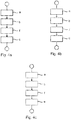
- Fig. 4a-4c
- show flow charts with respect to embodiments of the method to control a hybrid powertrain according to the present invention.
-
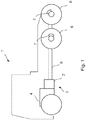
Fig. 1 shows a schematic side view of avehicle 1, comprising agearbox 2 and acombustion engine 4, which are comprised in ahybrid powertrain 3. Thecombustion engine 4 is connected to thegearbox 2, and thegearbox 2 is further connected to thedriving wheels 6 of thevehicle 1 via apropeller shaft 9. Thedriving wheels 6 are equipped withbrake devices 7 to brake thevehicle 1. -
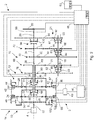
Fig. 2 shows a schematic side view of ahybrid powertrain 3 with agearbox 2, comprising aninput shaft 8, a first and a secondplanetary gear electrical machine countershaft 18 and anoutput shaft 20. The hybrid powertrain comprises acombustion engine 4, connected to thegearbox 2. Thecombustion engine 4 is connected with thegearbox 2 via theinput shaft 8 of the gearbox. The combustion engine has anoutput shaft 97. Theoutput shaft 97 of thecombustion engine 4 is connected to the input shaft of thegearbox 2. The firstplanetary gear 10 has a firstinternal ring gear 22, to which afirst rotor 24 in the firstelectrical machine 14 is connected. The firstplanetary gear 10 also has afirst sun wheel 26 and a firstplanetary wheel carrier 50. The firstplanetary gear 10 is connected to a firstmain shaft 34. The firstmain shaft 34 is connected with thefirst sun wheel 26, arranged in the firstplanetary gear 10. The secondplanetary gear 12 has a secondinternal ring gear 28, to which asecond rotor 30 of the secondelectrical machine 16 is connected. The secondplanetary gear 12 has asecond sun wheel 32 and a secondplanetary wheel carrier 51. The secondplanetary gear 12 is connected to a secondmain shaft 36. The first and thesecond sun wheels main shaft 34 arranged on thefirst sun wheel 26 extends inside a secondmain shaft 36, which is equipped with acentral boring 38, arranged on the secondplanetary wheel carrier 51. It is also possible to arrange the first andsecond sun wheels main shaft 34 and the secondmain shaft 36, in parallel with and next to each other. In this case, thecountershaft 18 is suitably arranged between the firstmain shaft 34 and the secondmain shaft 36, and the torque may be extracted directly from thecountershaft 18. Thecountershaft 18 thus constitutes, in this case, theoutput shaft 20. - The
combustion engine 4 is connected with the firstplanetary wheel carrier 50, and the firstplanetary wheel carrier 50 is connected with thesecond sun wheel 32. - The first
electrical machine 14 is equipped with afirst stator 40, which is connected to thevehicle 1, via agear housing 42 surrounding thegearbox 2. The secondelectrical machine 16 is equipped with asecond stator 44, which is connected to thevehicle 1, via agear housing 42 surrounding thegearbox 2. The first and the secondelectrical machine 16 are connected to anenergy storage device 46, such as a battery, which, depending on the vehicle's 1 operating mode, operates theelectrical machines electrical machines energy storage device 46. Anelectronic control device 48 is connected to theenergy storage device 46 and controls the supply of power to theelectrical machines energy storage device 46 is connected to theelectrical machines switch 49, which is connected to thecontrol device 48. Theelectrical machines electrical machines electrical machine switch 49, connected to theelectrical machines electrical machines control device 48 and thegearbox 2. By leading electric power from the firstelectrical machine electrical machine switch 49, no electric power will be led to and from theenergy storage device 46. Thus, conditions are created for an increased life of theenergy storage device 46. While controlling the hybrid drive line, it is possible to select a first and a second torque, which theelectrical machines electrical machines electrical machine electrical machines hybrid powertrain 3. It is therefore possible to control thehybrid powertrain 3 and to drive thevehicle 1 without theenergy storage device 46. - The first
planetary gear 10 is equipped with a firstplanetary wheel carrier 50, on which a first set ofplanetary wheels 52 is mounted. The secondplanetary gear 12 is equipped with a secondplanetary wheel carrier 51, on which a second set ofplanetary wheels 54 is mounted. The secondmain shaft 36 is connected with the secondplanetary wheel carrier 51, arranged in the secondplanetary gear 12. The first set ofplanetary wheels 52 interacts with the firstinternal ring gear 22 and thefirst sun wheel 26. The second set ofplanetary wheels 54 interacts with the secondinternal ring gear 28 and thesecond sun wheel 32. Theinput shaft 8 of thegearbox 2 is connected with the firstplanetary wheel carrier 50. The firstplanetary wheel carrier 50 in the firstplanetary gear 10 is directly and fixedly connected with thesecond sun wheel 32 of the secondplanetary gear 12. Thus, the firstplanetary wheel carrier 50 and thesecond sun wheel 32 will always have the same rotational direction and the same rotational speed. - A
first coupling device 56 is arranged between thefirst sun wheel 26 and the firstplanetary wheel carrier 50. By arranging thefirst coupling device 56 in such a way that thefirst sun wheel 26 and the firstplanetary wheel carrier 50 are connected with each other, and may therefore not rotate in relation to each other, the firstplanetary wheel carrier 50 and thefirst sun wheel 26 will rotate with equal rotational speeds. - A
second coupling device 58 is arranged between thesecond sun wheel 32 and the secondplanetary wheel carrier 51. By arranging thesecond coupling device 58 in such a way that thesecond sun wheel 32 and the secondplanetary wheel carrier 51 are connected with each other, and may therefore not rotate in relation to each other, the secondplanetary wheel carrier 51 and thefirst sun wheel 32 will rotate with equal rotational speeds. - Preferably, the first and
second coupling devices coupling sleeve planetary wheel carrier respective sun wheels respective coupling sleeve respective coupling sleeves planetary wheel carrier 50 and thefirst sun wheel 26, as well as the secondplanetary wheel carrier 51 and thesecond sun wheel 32, respectively, become mutually interlocked with each other and may not rotate in relation to each other. - The first and
second coupling device Fig. 2 are arranged between thefirst sun wheel 26 and the firstplanetary wheel carrier 50, and between thesecond sun wheel 28 and the secondplanetary wheel carrier 51, respectively. However, it is possible to arrange an additional or alternative coupling device (not displayed) between the firstinternal ring gear 22 and the firstplanetary wheel carrier 50, and also to arrange an additional or alternative coupling device (not displayed) between the secondinternal ring gear 28 and the secondplanetary wheel carrier 51. - The first
planetary wheel carrier 50 of the firstplanetary gear 10 in this embodiment is fixedly connected with thesecond sun wheel 32 of the secondplanetary gear 12. Alternatively, the firstplanetary wheel carrier 50 is fixedly connected with the secondinternal ring gear 28 of the secondplanetary gear 12. Alternatively, the firstmain shaft 34 is connected with afirst ring gear 22, arranged in the firstplanetary gear 10. - In this embodiment, a
third coupling device 59 is arranged between thefirst ring gear 22 and thegear house 42. By actuating thethird coupling device 59, so that thefirst ring gear 22 and thegear house 42 are connected with each other and accordingly may not rotate in relation to each other, a down-shift of torque will occur, that is to say an up-shift of the rotational speed from theplanetary wheel carrier 50 to thefirst sun wheel 26 will occur. - In this embodiment, a fourth coupling device 61 is arranged between the second
internal ring gear 28 and thegear house 42. By actuating the fourth coupling device 61, so that thesecond ring gear 28 and thegear house 42 are connected with each other and accordingly may not rotate in relation to each other, a down-shift of torque will occur, that is to say an up-shift of the rotational speed from theplanetary wheel carrier 51 to thesecond sun wheel 32 will occur. - Preferably the third and
fourth coupling device 59, 61 comprises a third and fourth splines equippedcoupling sleeve 65 and 67, respectively, which are axially shiftable on the respective splines-equipped sections of the first and second ring gears 22 and 28, as well as on a splines-equipped section of thegear house 42. By shifting therespective coupling sleeves 65, 67 in such a way that the splines-equipped sections are connected via therespective coupling sleeves 65, 67, thefirst ring gear 22 and thegear house 42, and thesecond ring gear 28 and thegear house 42, respectively, are interlocked and may not rotate in relation to each other. - A
transmission device 19, which comprises afirst gear pair 60, arranged between the firstplanetary gear 10 and theoutput shaft 20 is connected to the first and the secondmain shaft first gear pair 60 comprises afirst pinion gear 62 and afirst cogwheel 64, which are in engagement with each other. Asecond gear pair 66 is arranged between the secondplanetary gear 12 and theoutput shaft 20. Thesecond gear pair 66 comprises asecond pinion gear 68 and asecond cogwheel 70, which are in engagement with each other. Athird gear pair 72 is arranged between the firstplanetary gear 10 and theoutput shaft 20. Thethird gear pair 72 comprises athird pinion gear 74 and athird cogwheel 76, which are in engagement with each other. Afourth gear pair 78 is arranged between the secondplanetary gear 12 and theoutput shaft 20. Thefourth gear pair 78 comprises afourth pinion gear 80 and afourth cogwheel 82, which are in engagement with each other. - On the first
main shaft 34, the first and the third pinion gears 62 and 74, respectively, are arranged. The first and the third pinion gears 62 and 74, respectively, are fixedly connected with the firstmain shaft 34, so that they may not rotate in relation to the firstmain shaft 34. On the secondmain shaft 36, the second and the fourth pinion gears 68 and 80, respectively, are arranged. The second and the fourth pinion gears 68 and 80, respectively, are fixedly connected with the secondmain shaft 36, so that they may not rotate in relation to the secondmain shaft 36. - The
countershaft 18 extends substantially in parallel with the first and the secondmain shaft countershaft 18, the first, second, third andfourth cogwheels first pinion gear 62 engages with thefirst cogwheel 64, thesecond pinion gear 68 engages with thesecond cogwheel 70, thethird pinion gear 74 engages with thethird cogwheel 76 and thefourth pinion gear 80 engages with thefourth cogwheel 82. - The first, second, third and
fourth cogwheels countershaft 18 with the assistance of the first, second, third andfourth coupling elements coupling elements cogwheels countershaft 18, which interact with fifth andsixth coupling sleeves fourth cogwheel countershaft 18. The first andthird coupling elements common coupling sleeve 83, and the second andfourth coupling elements common coupling sleeve 85. In the released state, a relative rotation may occur between thecogwheels countershaft 18. Thecoupling elements fifth cogwheel 92 is also arranged, which engages with asixth cogwheel 94, which is arranged on theoutput shaft 20 of thegearbox 2. - The
countershaft 18 is arranged between the respective first and secondplanetary gears output shaft 20, so that thecountershaft 18 is connected with theoutput shaft 20 via afifth gear pair 21, which comprises the fifth and thesixth cogwheel fifth cogwheel 92 is arranged so it may be connected with and disconnected from thecountershaft 18 with afifth coupling element 93. - By disconnecting the
fifth cogwheel 92, which is arranged to be disconnectable from thecountershaft 18, it is possible to transfer torque from the secondplanetary gear 12 to thecountershaft 18 via thesecond gear pair 66, and to further transfer torque from thecountershaft 18 to theoutput shaft 20 via thefirst gear pair 60. Thus, a number of gear steps is obtained, wherein torque from one of theplanetary gears countershaft 18, and further along from thecountershaft 18 to themain shaft planetary gear output shaft 20 of thegearbox 2. This presumes, however, that acoupling mechanism 96 arranged between the firstmain shaft 34 and theoutput shaft 20 is connected, which is described in more detail below. - The
fifth cogwheel 92 may be locked to and released from thecountershaft 18 with the assistance of afifth coupling element 93. Thecoupling element 93 preferably consists of splines-equipped sections adapted on thefifth cogwheel 92 and thecountershaft 18, which sections interact with aninth coupling sleeve 87, which engages mechanically with the splines-equipped sections of thefifth cogwheel 92 and thecountershaft 18. In the released state, a relative rotation may occur between thefifth cogwheel 92 and thecountershaft 18. Thefifth coupling element 93 may also consist of friction clutches. - At a number of gearing situations, wherein the ring gears of the
planetary gears gear house 42 with the assistance of the third andfourth coupling devices 59, 61, torque will be downshifted after the firstplanetary gear 10 and up-shifted after the secondplanetary gear 12. When the torque transfer over the firstmain shaft 34 via thecountershaft 18 decreases after the firstplanetary gear 10, shafts, pinion gears and cogwheels connected thereto may be designed to be smaller, which makes thegearbox 2 more compact. A large number of gear steps may also be obtained without any need to arrange a number of additional gear pairs in the gearbox. Accordingly, the weight and cost of thegearbox 2 are also reduced. The fifth andsixth cogwheels fifth gear pair 21, which, at certain gear steps, up-shifts the torque to theoutput shaft 20 of thegearbox 2. - Torque transfer from the
input shaft 8 of thegearbox 2 to theoutput shaft 20 of thegearbox 2 may occur via the first or the secondplanetary gear countershaft 18. The torque transfer may also occur directly via the firstplanetary gear 10, whosefirst sun wheel 26 is connected, via the firstmain shaft 34, to theoutput shaft 20 of thegearbox 2 via acoupling mechanism 96. Thecoupling mechanism 96 preferably comprises a splines-equippedseventh coupling sleeve 100, which is axially shiftable on the firstmain shaft 34 and on the splines-equipped sections of theoutput shaft 20. By shifting theseventh coupling sleeve 100, so that the splines-equipped sections are connected via theseventh coupling sleeve 100, the firstmain shaft 34 becomes locked with theoutput shaft 20, which, when rotating, will therefore have the same rotational speed. By disconnecting thefifth cogwheel 92 of thefifth gear pair 21 from thecountershaft 18, torque from the secondplanetary gear 12 may be transferred to thecountershaft 18, and further along from thecountershaft 18 to the firstmain shaft 34, connected with the firstplanetary gear 10, in order finally to transfer torque via thecoupling mechanism 96 to theoutput shaft 20 of thegearbox 2. - In some operating modes the
gearbox 2 may operate so that one of thesun wheels planetary wheel carrier second coupling device main shaft input shaft 8 of thegearbox 2, depending on whichsun wheel planetary wheel carriers electrical machines energy storage device 46. Alternatively, theelectrical machine output shaft 20. At some operating times, theelectrical machines energy storage device 46. - In some operating modes the
gearbox 2 may operate in such a way that one of therotors electrical machines gear house 42 via the respective ring gears 22 and 28, while the secondelectrical machine energy storage device 46, which will be explained in more detail below. Theelectrical machine respective rotor gear house 42, absorbs a reaction torque from thering gear fourth coupling devices 59 and 61, respectively. Instead of operating as a generator, theelectrical machines output shaft 20. Torque balance comprises a substantially zero torque state on the one hand, and a counteracting torque on the other, in order for thecoupling devices 59, 61 to be put into a state, wherein they do not transfer torque between the ring gears 22, 28 and thegear house 42. - It is also possible that the total reaction torque of both the first and the second
electrical machine energy storage device 46. At engine braking the driver releases the accelerator pedal (not displayed) of thevehicle 1. Theoutput shaft 20 of thegearbox 2 then operates one or bothelectrical machines combustion engine 4 and theelectrical machines electrical machines energy storage device 46 in thevehicle 1. This operating state is referred to as regenerative braking. In order to facilitate more powerful braking effect theoutput shaft 97 of the combustion engine's 4 may be locked and thus be prevented from rotating. Thus, only one of or both theelectrical machines energy storage device 46. The locking of theoutput shaft 97 of thecombustion engine 4 may also be carried out when the vehicle must accelerate by only one or both theelectrical machines electrical machines planetary gears combustion engine 4 and having regard to the gearing between them, thecombustion engine 4 will not be able to resist the large torque, h theelectrical machines output shaft 97 of the combustion engine's 4. The locking of theoutput shaft 97 of thecombustion engine 4 is preferably carried out with alocking device 102, which is arranged between the firstplanetary wheel carrier 50 and the gear hosing 42. By locking the firstplanetary wheel carrier 50 and thegear housing 42, theoutput shaft 97 of thecombustion engine 4 will also be locked, since theoutput shaft 97 of thecombustion engines 4 is connected with the firstplanetary wheel carrier 50 via theinput shaft 8 of the gearbox. Thelocking device 102 preferably comprises a splines-equippedeighth coupling sleeve 104, which is axially shiftable on a splines-equipped section of the firstplanetary wheel carrier 50, and on a splines-equipped section of the gear housing. By shifting the eightcoupling sleeve 104 so that the splines-equipped sections are connected via thecoupling sleeve 104, the firstplanetary wheel carrier 50, and therefore theoutput shaft 97 of thecombustion engine 4 is prevented from rotating. - The
control device 48 is connected to theelectrical machines electrical machines output shaft 20 of thegearbox 2, and during other operating times use the kinetic energy of theoutput shaft 20 of thegearbox 2 to extract and store electric power. Thecontrol device 48 thus detects the rotational speed and/or the torque of theoutput shaft 97 of thecombustion engine 4 viasensors 98 arranged at theelectrical machines output shaft 20 of thegearbox 2, in order thus to gather information and to control theelectrical machines control device 48 may be a computer with software suitable for this purpose. Thecontrol device 48 also controls the flow of power between theenergy storage device 46 and therespective stators electrical machines electrical machines energy storage device 46 to therespective stators electrical machines respective stators energy storage device 46. However, as stated above, theelectrical machines energy storage device 46. - The first, second, third and
fourth coupling devices fifth coupling elements coupling mechanism 96 between the firstmain shaft 34 and theoutput shaft 20, and thelocking device 102 between the firstplanetary wheel carrier 50 and thegear housing 42, are connected to thecontrol device 48 via their respective coupling sleeves. These components are preferably activated and deactivated by electric signals from thecontrol device 48. The coupling sleeves are preferably shifted by non-displayed power elements, such as hydraulically or pneumatically operated cylinders. It is also possible to shift the coupling sleeves with electrically powered power elements. - The example embodiment in
Fig. 2 shows four pinion gears 62, 68, 74 and 80, respectively, and fourcogwheels planetary gears electrical machines gearbox 2 with more or fewer pinion gears and cogwheels, and with more planetary gears with associated electrical machines. - Below, an up-shift from the first to the highest gear will be described, wherein the
gearbox 2 is arranged in avehicle 1. The up-shift occurs while thecombustion engine 4 is in operation. Theinput shaft 8 of thegearbox 2 is connected with theoutput shaft 97 of thecombustion engine 4 of thevehicle 1. Theoutput shaft 20 of thegearbox 2 is connected to a drivingshaft 99 in thevehicle 1. At idling of thecombustion engine 4 and when thevehicle 1 is at a standstill, theinput shaft 8 of thegearbox 2 rotates at the same time as theoutput shaft 20 of thegearbox 2 is at a standstill. Thelocking device 102 is deactivated, so that theoutput shaft 97 of thecombustion engine 4 may rotate freely. Since theinput shaft 8 of thegearbox 2 rotates, the firstplanetary wheel carrier 50 will also rotate, which entails that the first set ofplanetary wheels 52 will rotate. Since the firstplanetary wheel carrier 50 is connected to thesecond sun wheel 32, thesecond sun wheel 32, and thus also the second set ofplanetary wheels 54, will rotate. By not supplying power to, or extracting power from, the first and the secondelectrical machines internal rings second rotor electrical machines internal rings fourth coupling devices combustion engine 4 to therespective sun wheels planetary gears coupling mechanism 96 between the firstmain shaft 34 and theoutput shaft 20 is disconnected, so that the firstmain shaft 34 and theoutput shaft 20 may rotate freely in relation to each other. Since theoutput shaft 20 of thegearbox 2 at this stage is at a standstill, thecountershaft 18 is also at a standstill. In a first step thefourth cogwheel 82 and thethird cogwheel 76 are connected with thecountershaft 18 with the assistance of the fourth andthird coupling elements first cogwheel 64 and thesecond cogwheel 70 are disconnected from thecountershaft 18. Thus, thefirst cogwheel 64 and thesecond cogwheel 70 are allowed to rotate freely in relation to thecountershaft 18. Thefifth cogwheel 92 of thefifth gear pair 21 is locked on thecountershaft 18 with the assistance of thefifth coupling element 93. - In order to start the rotation of the
output shaft 20 of thegearbox 2, with the objective of driving thevehicle 1, thefourth pinion gear 80 and thefourth cogwheel 82 on thecountershaft 18 must be brought to rotate. This is achieved by making the secondplanetary wheel carrier 51 rotate. When the second planetary wheel carrier rotates, the secondmain shaft 36 will also rotate, and thus thefourth pinion gear 80, which is arranged on the secondmain shaft 36, also rotates. The secondplanetary wheel carrier 51 is made to rotate by controlling the secondinternal ring gear 28 with the secondelectrical machine 16. By activating the secondelectrical machine 16 and controlling thecombustion engine 4 to a suitable engine speed, thevehicle 1 begins to move as the secondmain shaft 36 begins to rotate. When the secondplanetary wheel carrier 51 and thesecond sun wheel 32 achieve the same rotational speed, thesecond sun wheel 32 is locked with the secondplanetary wheel carrier 51 with the assistance of thesecond coupling device 58. As mentioned above, thesecond coupling device 58 is preferably adapted in such a way that thesecond sun wheel 32 and the secondplanetary wheel carrier 51 engage mechanically with each other. Alternatively, thesecond coupling device 58 may be adapted as a slip brake or a multi-plate clutch which connects, in a smooth way, thesecond sun wheel 32 with the secondplanetary wheel carrier 51. When thesecond sun wheel 32 is connected with the secondplanetary wheel carrier 51, the secondplanetary wheel carrier 51 will rotate with the same rotational speed as theoutput shaft 97 of thecombustion engine 4. Thus, the torque generated by thecombustion engine 4 is transferred to theoutput shaft 20 of thegearbox 2 via thefourth pinion gear 80, thefourth cogwheel 82 on thecountershaft 18, thefifth cogwheel 92 on thecountershaft 18, and thesixth cogwheel 94 on theoutput shaft 20 of thegearbox 2. Thevehicle 1 will thus begin to move off and be propelled by the first gear. - Each of the first, second, third and fourth gear pairs 60, 66, 72, 78 has a gearing, which is adapted to the vehicle's 1 desired driving characteristics. According to the example embodiment displayed in
Fig. 2 , thefourth gear pair 78 has the highest gearing compared to the first, second and third gear pairs 60, 66, 72, which results in thefourth gear pair 78 being connected when the lowest gear is engaged. Thesecond gear pair 66 transfers, as does thefourth gear pair 78, torque between the secondmain shaft 36 and thecountershaft 18, and could instead be fitted out with the highest gearing, compared with other gear pairs 60, 72, 78, which is why in such an embodiment thesecond gear pair 66 could be connected when the lowest gear is engaged. - When the
countershaft 18 is made to rotate by thefourth cogwheel 82 on thecountershaft 18, thethird cogwheel 76 on thecountershaft 18 will also rotate. Thus, thecountershaft 18 operates thethird cogwheel 76, which in turn operates thethird pinion gear 74 on the firstmain shaft 34. When the firstmain shaft 34 rotates, thefirst sun wheel 26 will also rotate, and thus, depending on the rotational speed of theoutput shaft 97 of thecombustion engine 4 and thus the rotational speed of the firstplanetary wheel carrier 50, it will cause the firstinternal ring gear 22 and thefirst rotor 24 of the firstelectrical machine 14 to rotate. It is thus possible to allow the firstelectrical machine 14 to operate as a generator to supply power to theenergy storage device 46, and/or to supply power to the secondelectrical machine 16. It is also possible for the secondelectrical machine 16 to be operated as a generator. Alternatively, the firstelectrical machine 14 may emit a torque injection, by way of thecontrol device 48 controlling the firstelectrical machine 14 to provide a driving torque. - In order to shift from a first gear to a second gear, the locking between the
second sun wheel 32 and the secondplanetary wheel carrier 51 must cease, which is achieved by way of the first and/or the secondelectrical machine planetary gear 12. Subsequently, thesecond coupling device 58 is controlled, so that it disconnects thesecond sun wheel 32 and the secondplanetary wheel carrier 51 from each other. The secondplanetary wheel carrier 51 and also the secondmain shaft 36 may rotate freely, which entails that thesecond sun wheel 32, the secondplanetary wheel carrier 51 and the secondmain shaft 36 no longer operate thefourth pinion gear 80, arranged on the secondmain shaft 36. This assumes that the secondelectrical machine 16 does not operate thesecond ring gear 28. The second gear is connected, by way of thecontrol device 48 controlling thecombustion engine 4, so that a synchronous rotational speed arises between the firstplanetary wheel carrier 50 and thefirst sun wheel 26, in order to achieve a locking between the firstplanetary wheel carrier 50 and thefirst sun wheel 26. This is achieved by way of controlling thefirst coupling device 56 in such a way that the firstplanetary wheel carrier 50 and thefirst sun wheel 26 are mechanically connected with each other. Alternatively, thefirst coupling device 56 may be adapted as a slip brake or a multi-plate clutch which connects, in a smooth way, thefirst sun wheel 26 with the firstplanetary wheel carrier 50. By synchronising the control of thecombustion engine 4 and the second and firstelectrical machine - The first
main shaft 34 now rotates, operated by theoutput shaft 97 of thecombustion engine 4, and the firstmain shaft 34 now operates thethird pinion gear 74. Thus, the firstplanetary wheel carrier 50 now operates thethird pinion gear 74, via thefirst sun wheel 26 and the firstmain shaft 34. Since thethird cogwheel 76 is in engagement with thethird pinion gear 74 and is connected with thecountershaft 18, thethird cogwheel 76 will operate thecountershaft 18, which in turn operates thefifth cogwheel 92 on thecountershaft 18. Thefifth cogwheel 92 in turn operates theoutput shaft 20 of thegearbox 2 via thesixth cogwheel 94, which is arranged on theoutput shaft 20 of thegearbox 2. Thevehicle 1 is now driven with the second gear engaged. - When the
countershaft 18 is made to rotate by thethird cogwheel 76, thefourth cogwheel 82 will also rotate. Thus, thecountershaft 18 operates thefourth cogwheel 82, which in turn operates thefourth pinion gear 80 on the secondmain shaft 36. When the secondmain shaft 36 rotates, the secondplanetary wheel carrier 51 will also rotate, and thus, depending on the rotational speed of theoutput shaft 97 of thecombustion engine 4, and thus the rotational speed in the firstplanetary wheel carrier 50, it will cause the secondinternal ring gear 28 and thesecond rotor 30 of the secondelectrical machine 16 to rotate. It is thus possible to allow the secondelectrical machine 16 to operate as a generator to supply power to theenergy storage device 46, and/or to supply power to the firstelectrical machine 14. The secondelectrical machine 16 may also emit a torque injection, by way of thecontrol device 48 controlling the secondelectrical machine 16 to provide a propulsion torque. - In order to shift from the second gear to the third gear, the
fourth cogwheel 82 on thecountershaft 18 must be disconnected from thecountershaft 18 with thefourth coupling element 90, so that thefourth cogwheel 82 may rotate freely in relation to thecountershaft 18. Subsequently, thecountershaft 18 is connected with thesecond cogwheel 70 on thecountershaft 18 via thesecond coupling element 86. In order to achieve a connection of thecountershaft 18 and thesecond cogwheel 70 on thecountershaft 18, preferably the secondelectrical machine 16 is controlled in such a way that a synchronous rotational speed arises between thecountershaft 18 and thesecond cogwheel 70 on thecountershaft 18. A synchronous rotational speed may be achieved by way of measuring the rotational speed in thesecond rotor 30 in the secondelectrical machine 16, and measuring the rotational speed in theoutput shaft 20. Thus, the rotational speed in the secondmain shaft 36 and the rotational speed in thecountershaft 18 may be determined by way of given gear ratios. The rotational speed of therespective shafts countershaft 18 and thesecond cogwheel 70, thecountershaft 18 and thesecond cogwheel 70 are connected with the assistance of thesecond coupling element 86. - In order to complete the shift from a second gear to the third gear, the locking between the
first sun wheel 26 and the firstplanetary wheel carrier 50 must cease, which is achieved by way of the first and/or the secondelectrical machine planetary gear 10, following which thefirst coupling device 56 is controlled, in such a way that it disconnects thefirst sun wheel 26 and the firstplanetary wheel carrier 50 from each other. Subsequently, thecombustion engine 4 is controlled in such a way that a synchronous rotational speed arises between thesecond sun wheel 32 and the secondplanetary wheel carrier 51, so that thesecond coupling device 58 may be engaged in order thus to connect thesecond sun wheel 32 with the secondplanetary wheel carrier 51, via thecoupling sleeve 57. By synchronising the control of thecombustion engine 2 and the second and firstelectrical machine - The
third cogwheel 76 is disconnected by controlling the firstelectrical machine 14 in such a way that a substantially zero torque state arises between thecountershaft 18 and thethird cogwheel 76. When a substantially zero torque state arises, thethird cogwheel 76 is disconnected from thecountershaft 18 by controlling thethird coupling element 88, so that it releases thethird cogwheel 76 from thecountershaft 18. Subsequently, the firstelectrical machine 14 is controlled in such a way that a synchronous rotational speed arises between thecountershaft 18 and thefirst cogwheel 64. When a synchronous rotational speed arises, thefirst cogwheel 64 is connected to thecountershaft 18 by way of controlling thefirst coupling element 84, so that it connects thefirst cogwheel 64 on thecountershaft 18. A synchronous rotational speed may be determined, since the rotational speed of thefirst rotor 24 in the firstelectrical machine 14 is measured and the rotational speed of theoutput shaft 20 is measured, following which the rotational speeds of theshafts main shaft 34 and the rotational speed of thecountershaft 18 may be determined by way of given gear ratios. - The second
main shaft 36 now rotates with the same rotational speed as theoutput shaft 97 of thecombustion engine 4, and the secondmain shaft 36 now operates thesecond pinion gear 68 via the secondmain shaft 36. Since thesecond cogwheel 70 is in engagement with thesecond pinion gear 68 and is connected with thecountershaft 18, thesecond cogwheel 70 will operate thecountershaft 18, which in turn operates thefifth cogwheel 92 on thecountershaft 18. Thefifth cogwheel 92 in turn operates theoutput shaft 20 of thegearbox 2 via thesixth cogwheel 94, which is arranged on theoutput shaft 20 of thegearbox 2. Thevehicle 1 is now driven in a third gear. - When the
countershaft 18 is made to rotate by thesecond cogwheel 70 on thecountershaft 18, thefirst cogwheel 64 on thecountershaft 18 will also rotate. Thus, thecountershaft 18 operates thefirst cogwheel 64, which in turn operates thefirst pinion gear 62 on the firstmain shaft 34. When the firstmain shaft 34 rotates, thefirst sun wheel 26 will also rotate, and thus, depending on the rotational speed of theoutput shaft 97 of thecombustion engine 4, and thus the rotational speed of the firstplanetary wheel carrier 50, it will cause the firstinternal ring gear 22 and thefirst rotor 24 of the secondelectrical machine 16 to rotate. It is thus possible to allow the firstelectrical machine 14 to operate as a generator to supply power to theenergy storage device 46, and/or to supply power to the secondelectrical machine 16. Alternatively, the firstelectrical machine 14 may emit a torque injection, by way of thecontrol device 48 controlling the firstelectrical machine 14 to provide a driving torque. - In order to complete the shift from the third to the fourth gear, the locking between the
second sun wheel 32 and the secondplanetary wheel carrier 51 must cease, which is achieved by way of the first and/or the secondelectrical machine planetary gear 12, following which thesecond coupling device 58 is controlled in such a way that it disconnects thesecond sun wheel 32 and the secondplanetary wheel carrier 51 from each other. Subsequently, thefirst ring gear 22 is decelerated, and when thefirst ring gear 22 is at a standstill thethird coupling device 59 is controlled in such a way that thefirst ring gear 22 is connected and joined with thegear house 42. By synchronising the control of thecombustion engine 4 and the second and firstelectrical machine - The first
main shaft 34 is now operated by theoutput shaft 97 of thecombustion engine 4, and the firstmain shaft 34 now operates thefirst pinion gear 62. Since thefirst cogwheel 64 is in engagement with thefirst pinion gear 62 and is connected with thecountershaft 18, thefirst cogwheel 64 will operate thecountershaft 18, which in turn operates thefifth cogwheel 92 on thecountershaft 18. Thefifth cogwheel 92 in turn operates theoutput shaft 20 of thegearbox 2 via thesixth cogwheel 94, which is arranged on theoutput shaft 20 of thegearbox 2. Thevehicle 1 is now driven in a fourth gear. - When the
countershaft 18 is made to rotate by thefirst cogwheel 64, thesecond cogwheel 70 on thecountershaft 18 will also rotate. Thus, thecountershaft 18 operates thesecond cogwheel 70, which in turn operates thesecond pinion gear 68 on the secondmain shaft 36. When the secondmain shaft 36 rotates, the secondplanetary wheel carrier 51 will also rotate, and thus, depending on the rotational speed of theoutput shaft 97 of thecombustion engine 4 and thus the rotational speed in the firstplanetary wheel carrier 50, it will cause thesecond sun wheel 32 and thesecond rotor 28 of the secondelectrical machine 16 to rotate. It is thus possible to allow the secondelectrical machine 16 to operate as a generator to supply power to theenergy storage device 46, and/or to supply power to the firstelectrical machine 14. Alternatively, the secondelectrical machine 16 may also emit a torque injection by way of thecontrol device 48, controlling the secondelectrical machine 16 in order to provide a propulsion torque. - In order to shift from the fourth gear to the fifth gear, the first
electrical machine 14 is controlled, in such a way that torque balance prevails between thefirst ring gear 22 and thegearbox house 42. When torque balance prevails between thefirst ring gear 22 and thegear house 42, thethird coupling device 59 is controlled in such a way that thefirst ring gear 22 is disconnected from thegear house 42. Subsequently, the firstelectrical machine 14 is controlled in such a way that a substantially zero torque state arises between thecountershaft 18 and thefirst cogwheel 64. When a substantially zero torque state arises between thecountershaft 18 and thefirst cogwheel 64, thefirst coupling element 84 is controlled in such a way that thefirst cogwheel 64 is disconnected from thecountershaft 18. Thus, the fourth gear has been disengaged. In order to engage the fifth gear, the firstelectrical machine 14 is controlled in such a way that a synchronous rotational speed arises between the firstmain shaft 34 and theoutput shaft 20. When a synchronous rotational speed arises between the firstmain shaft 34 and theoutput shaft 20, thecoupling mechanism 96 is controlled in such a way that the firstmain shaft 34 and theoutput shaft 20 are connected and joined with each other. Subsequently, the firstelectrical machine 14 is controlled in such a way that a substantially zero torque state arises between thecountershaft 18 and thefirst cogwheel 92 of thefifth gear pair 21. When a substantially zero torque state arises between thecountershaft 18 and thefifth cogwheel 92, thefifth coupling element 93 is controlled in such a way that thefifth cogwheel 92 is disconnected from thecountershaft 18. Subsequently, the firstelectrical machine 14 is controlled in such a way that a synchronous rotational speed arises between thecountershaft 18 and thefirst cogwheel 64. When a synchronous rotational speed arises between thecountershaft 18 and thefirst cogwheel 64, thecoupling element 84 is controlled in such a way that thefirst cogwheel 64 is connected and joined with thecountershaft 18. Finally, thecombustion engine 4 is controlled in such a way that thesecond ring gear 28 comes to a standstill in relation to thegear house 42. When thesecond ring gear 28 is at a standstill, the fourth coupling device 61 is controlled in such a way that thesecond ring gear 28 is connected and locked with thegear house 42. Thus, thevehicle 1 is now driven in the fifth gear. - When the fifth gear is engaged, torque from the
combustion engine 4 will pass the first and secondplanetary wheel carriers main shaft 36 via thesecond gear pair 66 to thecountershaft 18, and further along via thefirst gear pair 60 to the firstmain shaft 34, in order subsequently to be transferred to theoutput shaft 20 via thecoupling mechanism 96. - In order to shift from the fifth gear to the sixth gear, the second
electrical machine 16 is controlled in such a way that torque balance prevails between thesecond ring gear 28 and thegear house 42. When torque balance prevails between thesecond ring gear 28 and thegear house 42, the fourth coupling device 61 is controlled in such a way that thesecond ring gear 28 is disconnected from thegear house 42. Subsequently thecombustion engine 4 is controlled in such a way that a synchronous rotational speed arises between thefirst sun wheel 26 and the firstplanetary wheel carrier 50. When a synchronous rotational speed arises between thefirst sun wheel 26 and the firstplanetary wheel carrier 50, thefirst coupling device 56 is controlled in such a way that thefirst sun wheel 26 is connected and joined with the firstplanetary wheel carrier 50. Subsequently, the firstelectrical machine 16 is controlled in such a way that a substantially zero torque state arises between thecountershaft 18 and thefirst cogwheel 64. When a substantially zero torque state arises between thecountershaft 18 and thefirst cogwheel 64, thecoupling element 84 is controlled in such a way that thefirst cogwheel 64 is disconnected from thecountershaft 18. Finally, the secondelectrical machine 16 is controlled in such a way that a synchronous rotational speed arises between thecountershaft 18 and thethird cogwheel 76. When a synchronous rotational speed arises between thecountershaft 18 and thethird cogwheel 76, thecoupling element 88 is controlled in such a way that thethird cogwheel 76 is connected and joined with thecountershaft 18. Thus, thevehicle 1 is now driven in the sixth gear. - When the sixth gear is engaged, torque from the
combustion engine 4 will be transferred from the firstplanetary wheel carrier 50 to thefirst sun wheel 26, and further along to the firstmain shaft 34, in order subsequently to be transferred to theoutput shaft 20 via thecoupling mechanism 96. - In order to shift from the sixth gear to the seventh gear the first and/or the second
electrical machines planetary gear 12. When torque balance prevails in the secondplanetary gear 12, thefirst coupling device 56 is controlled in such a way that thefirst sun wheel 26 is disconnected from the firstplanetary wheel carrier 50. Subsequently thecombustion engine 4 is controlled in such a way that a synchronous rotational speed arises between thesecond sun wheel 32 and the secondplanetary wheel carrier 51. When a synchronous rotational speed arises between thesecond sun wheel 32 and the secondplanetary wheel carrier 51, thesecond coupling device 58 is controlled in such a way that thesecond sun wheel 32 is connected and joined with the secondplanetary wheel carrier 51. Thus, thevehicle 1 is now driven in the seventh gear. - When the seventh gear is engaged, torque from the
combustion engine 4 will pass the firstplanetary wheel carrier 50 and further along to the secondmain shaft 36. Subsequently, torque is transferred from the secondmain shaft 36 via thesecond gear pair 66 to thecountershaft 18, and further via thethird gear pair 72 to the firstmain shaft 34, in order subsequently to be transferred to theoutput shaft 20 via thecoupling mechanism 96. - According to the embodiment above, the
gearbox 2 comprises pinion gears 62, 68, 74, 80 andcogwheels main shafts countershaft 18, respectively, to transfer rotational speed and torque. However, it is possible to use another type of transmission, such as chain and belt drives, to transfer rotational speed and torque in thegearbox 2. - The
transmission device 19 has four gear pairs 60, 66, 72, 78 according to the example embodiment. However, thetransmission device 19 may comprise any number of gear pairs. -
Fig. 3 illustrates thehybrid powertrain 3 according toFig. 2 in a simplified view, where some components have been excluded in the interest of clarity. G1 inFig. 3 consists of at least one gear pair connected with the firstmain shaft 34 and therefore with the firstplanetary gear 10, and a gear pair G2 consists of at least one gear pair connected with the secondmain shaft 36 and therefore with the secondplanetary gear 12. These gear pairs G1, G2 are also connected to theoutput shaft 20 via thecountershaft 18. G1 and G2, respectively, may consist of one or several gear pairs. The gear pair G1, connected with the firstplanetary gear 10, may for example consist of thefirst gear pair 60 and/or thethird gear pair 72, as described inFig. 2 . The gear pair G2, connected with the secondplanetary gear 12, may for example consist of thesecond gear pair 66 and/or thefourth gear pair 78, as described inFig. 2 . Further, at least one gear pair G3, connected with theoutput shaft 20 and the countershaft, 18 is displayed, which may consist of thefifth gear pair 21 described inFig. 2 . G3 may consist of one or several gear pairs. Alternatively, theoutput shaft 20 may be omitted, so that torque may be extracted directly from thecountershaft 18, which thus constitutes the output shaft. - The at least one gear pair G1, 60, 72, connected with the first
planetary gear 10 comprises at least onepinion gear cogwheel pinion gear main shaft 34, arranged with the firstplanetary gear 10. The at least onecogwheel countershaft 18. - The at least one gear pair G2, 66, 78, connected with the second
planetary gear 12, comprises at least onepinion gear cogwheel pinion gear main shaft 36, arranged with the firstplanetary gear 12. The at least onecogwheel countershaft 18. - In
Fig. 3 , the third andfourth coupling devices 59 and 61 have been excluded. According to this embodiment of the invention, it is still possible to drive the vehicle in a number of operating modes and driving modes. As an example, the shift from one gear to another will be described. The components displayed inFig. 2 andFig. 3 are used to describe the shifting process. A gear is engaged when thefirst coupling device 56 is connected, and thus joins thefirst sun wheel 26 and a firstplanetary wheel carrier 50 arranged in the firstplanetary gear 10 with each other, while simultaneously thesecond coupling device 58 is disconnected, and thus disconnects thesecond sun wheel 32 and the secondplanetary wheel carrier 51, arranged in the secondplanetary gear 12, are from each other. At this gear the firstmain shaft 34 is operated by theoutput shaft 97 of thecombustion engine 4, and when needed by the firstelectrical machine 14, which results in the firstmain shaft 34 operating thefirst pinion gear 62. Since thefirst cogwheel 64 is in engagement with thefirst pinion gear 62 and is connected with thecountershaft 18 via thefirst coupling element 84, thefirst cogwheel 64 will operate thecountershaft 18, which in turn operates thefifth cogwheel 92 on thecountershaft 18. Thefifth cogwheel 92 in turn operates theoutput shaft 20 of thegearbox 2 via thesixth cogwheel 94, which is arranged on theoutput shaft 20 of thegearbox 2. - In order to shift to a next gear, the second
electrical machine 16 is controlled in such a way that a propulsion torque is generated via the secondmain shaft 36 and via thesecond gear pair 66, whereat thesecond cogwheel 70 of thesecond gear pair 66 is connected to thecountershaft 18 via thesecond coupling element 86. The propulsion torque further transmitted via thefifth gear pair 21 and finally to theoutput shaft 20. - In order to disengage the
first cogwheel 64 from thecountershaft 18, so that the fourth gear is disconnected, thecombustion engine 4 and the firstelectric machine 14 are first controlled in such a way that thefirst cogwheel 64 is brought to a substantially zero torque state in relation to thecountershaft 18. When a substantially zero torque state has arisen, thefirst coupling element 84 is disengaged, so that thefirst cogwheel 64 is disconnected from thecountershaft 18. - Subsequently, the rotational speed of the first
main shaft 34 is synchronised with the rotational speed of theoutput shaft 20, following which thecoupling mechanism 96 is controlled in such a way that it connects the firstmain shaft 34 with theoutput shaft 20. - Subsequently, the
combustion engine 4 and the firstelectrical machine 14 are controlled in such a way that the propulsion torque occurs via the firstmain shaft 34 and via thecoupling mechanism 96, and further along to theoutput shaft 20. By reducing the propulsion torque from the secondelectrical machine 16, thefifth coupling element 93 may be brought to a substantially zero torque state in relation to thecountershaft 18. When a substantially zero torque state has arisen, thefifth coupling element 93 is disengaged, so that thefifth cogwheel 92 of thefifth gear pair 21 is disconnected from thecountershaft 18. - Subsequently, with the help of the second
electrical machine 16, the rotational speed of thecountershaft 18 is synchronised with the rotational speed of thethird cogwheel 76, following which thethird coupling element 88 is controlled in such a way that it connects thethird cogwheel 76 with thecountershaft 18. When this connection has been completed, the propulsion torque may be shared between thecombustion engine 4, the firstelectrical machine 14 and the secondelectrical machine 16. Subsequently, torque balance is created in the firstplanetary gear 10, following which thefirst coupling device 56 disconnects the firstplanetary wheel carrier 50 and thefirst sun wheel 26 from each other. Finally, the secondplanetary wheel carrier 51 is rotational speed synchronised with thesecond sun wheel 32, following which thesecond coupling device 58 connects the secondplanetary wheel carrier 51 and thesecond sun wheel 32 with each other. - As described, torque is extracted from the
gearbox 2, from theoutput shaft 20. It is also possible to extract torque directly from the first or secondmain shaft countershaft 18. Torque may also be extracted in parallel from two or all of the threeshafts - Below is a description of an embodiment for control of the
hybrid powertrain 3, which may for example be applied when moving off thevehicle 1. The third andfourth coupling devices 59 and 61 have been excluded, since they are not needed in the method to control thehybrid powertrain 3. - In order to move off the vehicle, first the
combustion engine 4 is started, unless it already has been started, and subsequently, thefirst sun wheel 26 and the firstplanetary wheel carrier 50 are disconnected from each other with thefirst coupling device 56, and thesecond sun wheel 32 and the secondplanetary wheel carrier 51 are disconnected from each other with thesecond coupling device 58. In order to transmit torque to theoutput shaft 20, gears corresponding to the third and fourth gear pairs 72, 78 are engaged, by way of connecting the third andfourth cogwheels countershaft 18 to engage the gears. - The
fifth cogwheel 92 of thefifth gear pair 21, which is arranged to be disconnectable on thecountershaft 18, is locked on thecountershaft 18. Subsequently, the firstelectrical machine 14 and the secondelectrical machine 16 are activated, so that the firstelectrical machine 14 rotates in the opposite direction to the secondelectrical machine 16, which entails that a torque is generated in theoutput shaft 20. The firstelectrical machine 14 is activated to exert a first torque T1, and the secondelectrical machine 16 is activated to exert a second torque T2, wherein the size of the first and the second torque T1, T2 influence the power output P from the first and the secondelectrical machines - The desired powertrain torque TD, and therefore the desired torque in the
output shaft 20, are created by way of a combination of torque from the first and secondelectrical machines electrical machines electrical machines - In cases where the gear pair G3, which is connected with the
countershaft 18 and theoutput shaft 20, is connected and locked on thecountershaft 18, and a coupling mechanism S6, 96, arranged between the firstmain shaft 34 and theoutput shaft 20 is open, the torque TD desired in theoutput shaft 20 of the gearbox, also referred to as the powertrain torque, may be obtained through a combination of torque from the first and the secondelectrical machines 
electrical machine 14 emits and T2 is the torque emitted by the secondelectrical machine 16. K1 and K2 are constants, which are determined by the number of cogs on the component parts of the respectiveplanetary gears main shaft 34 and thecountershaft 18, G2 is the gear ratio between the secondmain shaft 36 and thecountershaft 18, and G3 is the gear ratio between thecountershaft 18 and theoutput shaft 20, for the selected connected gear pairs. - In cases where the gear pair G3, which is connected with the
countershaft 18 and theoutput shaft 20, is disconnected from thecountershaft 18, and thecoupling mechanism 96 is locked and thus connects the firstmain shaft 34 and theoutput shaft 20, the torque TD in theoutput shaft 20 of the gearbox is determined by the equation E1' below:

electrical machine 14 and n 2 is the engine speed of the secondelectrical machine 16. - The total power PE from the
electrical machines electrical machines energy storage device 46 will not be used. It is thus possible according to the invention to select a first and a second torque T1, T2, which the electrical machines must generate in order to obtain a certain power output in each one of theelectrical machines electrical machine electrical machine 14 is used to control the voltage between theelectrical machines electrical machine 16 is controlled in order to emit a desired torque T2. Thus, the frequency of extraction and supply of power from and to theenergy storage device 46 decreases, which results in an increase of the life of theenergy storage device 46. Thus, it is also possible that the energy storage device may be excluded. - When the
second sun wheel 32 and the secondplanetary wheel carrier 51 rotate with a synchronous rotational speed, thesecond sun wheel 32, arranged in the secondplanetary gear 12, and a secondplanetary wheel carrier 51 are connected with each other, via thesecond coupling device 58, so that thevehicle 1 may be operated exclusively by thecombustion engine 4. - According to another embodiment of the method, it is ensured that the first planetary gear's rotatable components are locked with each other, and that the second planetary gear's rotatable components are disconnected from each other. According to the invention, the first electrical machine controls the voltage between the electrical machines, while simultaneously the second electrical machine is controlled in order to emit a predetermined torque.
- According to another embodiment of the method, it is ensured that the first planetary gear's rotatable components are disconnected from each other, and that two of the second planetary gear's rotatable components are locked with each other. According to the invention, the second electrical machine controls the voltage between the electrical machines, while simultaneously the first electrical machine is controlled in order to emit a predetermined torque.
- These embodiments are applicable at different operating modes in the
hybrid powertrain 3 and thevehicle 1, in which thehybrid powertrain 3 is arranged. - The method to control a
hybrid drive line 3 according to the invention, comprises acombustion engine 4; a gearbox with aninput shaft 8 and anoutput shaft 20, which combustion engine is connected to theinput shaft 8; a firstplanetary gear 10, which is connected to the input shaft 8: a secondplanetary gear 12, connected to the firstplanetary gear 10; a firstelectrical machine 14, connected to the firstplanetary gear 10; a secondelectrical machine 16, connected to the secondplanetary gear 12; at least one gear pair G1, 60, 72 connected with the firstplanetary gear 10 and theoutput shaft 20; and at least one gear pair G2, 66, 78 connected with the secondplanetary gear 12 and theoutput shaft 20. -
Figures 4a - 4c show flow charts relating to embodiments of the innovative method for control of thehybrid powertrain 3. The first embodiment, which is displayed inFig. 4a comprises the steps: - a) to ensure that at least one gear is engaged, corresponding to the at least one gear pair G1, 60, 72, connected with the first
planetary gear 10, and/or the at least one gear pair G2, 66, 78, connected with the secondplanetary gear 12, and - b) to activate the first
electrical machine 14 and the secondelectrical machine 16, in such a way that the total electric power output from the first and secondelectrical machines output shaft 20. - Preferably, a torque is generated in the
output shaft 20 via thecombustion engine 4 and via at least one of the first and the secondelectrical machines rotatable components planetary gear 10 are disconnected from each other, and that therotatable components planetary gear 12 are disconnected from each other. - Preferably a
first sun wheel 26 and a firstplanetary wheel carrier 50, arranged in the firstplanetary gear 10, are disconnected from each other in step c) with the use of afirst coupling device 56; and asecond sun wheel 32 and a secondplanetary wheel carrier 51, arranged in the secondplanetary gear 12, are disconnected from each other with the use of asecond coupling device 58. - Preferably, in step c) the first
electrical machine 14 is controlled to control the voltage between theelectrical machines electrical machine 16 is controlled to emit a predetermined torque T2. - According to another embodiment, displayed in
Fig. 4b , in the additional step d), it is ensured that therotatable components planetary gear 10 are locked with each other, and that therotatable components planetary gear 12 are disconnected from each other. - Preferably a
first sun wheel 26 and a firstplanetary wheel carrier 50, arranged in the firstplanetary gear 10, are locked with each other in step d), with the use of afirst coupling device 56; and asecond sun wheel 32 and a secondplanetary wheel carrier 51, arranged in the secondplanetary gear 12, are disconnected from each other with the use of asecond coupling device 58. - Preferably, in step d) the first
electrical machine 14 is controlled to control the voltage between theelectrical machines electrical machine 16 is controlled to emit a predetermined torque T2. - According to another embodiment, displayed in
Fig. 4c , in the additional step e), it is ensured that therotatable components planetary gear 10 are disconnected from each other, and that therotatable components planetary gear 12 are locked with each other. - Preferably a
first sun wheel 26 and a firstplanetary wheel carrier 50, arranged in the firstplanetary gear 10, are disconnected from each other in step e) with the use of afirst coupling device 56; and asecond sun wheel 32 and a secondplanetary wheel carrier 51, arranged in the secondplanetary gear 12, are locked with each other with the use of asecond coupling device 58. - Preferably, in step e) the second
electrical machine 16 is controlled to control the voltage between theelectrical machines electrical machine 14 is controlled to emit a predetermined torque T1. - Preferably, the
combustion engine 4 is connected with the firstplanetary wheel carrier 50, which is connected with thesecond sun wheel 32. - Preferably, the at least one gear pair G1, 60, 72, connected with the first
planetary gear 10, comprises at least onepinion gear cogwheel pinion gear main shaft 34, arranged with the firstplanetary gear 10, and which cogwheel 64, 76 is arranged to be connectible and disconnectable on acountershaft 18; and the at least one gear pair G2, 66, 78, connected with the secondplanetary gear 12 comprises at least onepinion gear cogwheel pinion gear main shaft 36, arranged with the firstplanetary gear 12, and which cogwheel 70, 82 is arranged to be connectible and disconnectable on acountershaft 18, wherein in step a) the pinion gears 62, 74, 68, 80 are connected to themain shafts cogwheels countershaft 18 to engage the gears. - Preferably, there is at least one gear pair G3, 21 connected with a
countershaft 18 and theoutput shaft 20, comprising afifth cogwheel 92, which is arranged to be disconnectable on thecountershaft 18, and after the step b), in step f), thefifth cogwheel 92 is locked on thecountershaft 18. - Preferably, in step b) the first and the second
electrical machines electrical machine 14 rotates in the opposite direction to the secondelectrical machine 16. - Preferably, the first
electrical machine 14 is activated in step b) to exert a first torque T1, and the secondelectrical machine 16 is activated to exert a second torque T2, wherein the size of the first and the second torque T1, T2 influences the power output P from the first and the secondelectrical machines output shaft 20. - According to the invention, a computer program stored in the
control device 48 and/or in the computer 53, which computer program may comprise procedures to control the hybrid powertrain, is provided. - The program P may be stored in an executable manner, or in a compressed manner, in a memory M and/or a read/write memory R.
- The invention also relates to a computer program product, comprising program code stored in a medium readable by a computer, in order to perform the method steps specified above, when said program code is executed in the
control device 48, or in another computer 53 connected to thecontrol device 48. Said program code may be stored in a non-volatile manner on said medium readable by a computer 53. - The components and features specified above may, within the framework of the invention, be combined between different embodiments specified.
Claims (15)
- Method to control a hybrid powertrain (3), comprising a combustion engine (4); a gearbox (2) with an input shaft (8) and an output shaft (20); a first planetary gear (10), which comprises rotatable components (22, 26, 50) and is connected to the input shaft (8) and a first main shaft (34); a second planetary gear (12), which comprises rotatable components (28, 32, 51) and is connected to the first planetary gear (10) and a second main shaft (36); a first electrical machine (14), which is connected to the first planetary gear (10); a second electrical machine (16), which is connected to the second planetary gear (12), wherein the electrical machines (14, 16) may operate each other; at least one gear pair (G1, 60, 72) connected with the first planetary gear (10) and the output shaft (20); and at least one gear pair (G2, 66, 78) connected with the second planetary gear (12) and the output shaft (20), wherein the combustion engine is connected with a first planetary wheel carrier (50), arranged in the first planetary gear (10) via the input shaft (8), and wherein the second main shaft (36) is connected with a planetary wheel carrier (51), arranged in the second planetary gear (12), the method comprising the steps, while the combustion engine (4) is in operation:a) to ensure that at least one gear is engaged, corresponding to the at least one gear pair (G1, 60, 72), connected with the first planetary gear (10), and/or corresponding to the at least one gear pair (G2, 66, 78) connected with the second planetary gear (12),b) to activate the first electrical machine (14) and the second electrical machine (16), in such a way that the total electric power output from the first and second electrical machines (14, 16) is substantially zero, and in such a way that a torque is generated in the output shaft (20), characterised byc) ensuring that the rotatable components (26, 50) of the first planetary gear (10) are disconnected from each other, and that the rotatable components (32, 51) of the second planetary gear (12) are disconnected from each other, and disconnecting, with a first coupling device (56), a first sun wheel (26) arranged in the first planetary gear (10), and a first planetary wheel carrier (50), from each other; and disconnecting, with a second coupling device (58), a second sun wheel (32) arranged in the second planetary gear (12), and a second planetary wheel carrier (51), from each other.
- Method according to claim1 1, characterised in that, in step c) the first electrical machine (14) is controlled to control the voltage between the electrical machines (14, 16), while simultaneously the second electrical machine (16) is controlled to emit a predetermined torque (T2).
- Method according to claim 1, characterised by ensuring, in the additional step d), that the rotatable components (26, 50) of the first planetary gear (10) are locked with each other, and that the rotatable components (32, 51) of the second planetary gear (12) are disconnected from each other.
- Method according to claim 3, characterised by, in step d) locking, with the use of a first coupling device (56), a first sun wheel (26) arranged in the first planetary gear (10), and a first planetary wheel carrier (50), with each other; and disconnecting, with the use of a second coupling device (58), a second sun wheel (32), arranged in the second planetary gear (12), and a second planetary wheel carrier (51), from each other.
- Method according to any of claims 3 or 4, characterised in that, in step d) the first electrical machine (14) is controlled to control the voltage between the electrical machines (14, 16), while simultaneously the second electrical machine (16) is controlled to emit a predetermined torque (T2).
- Method according to claim 1, characterised by ensuring, in the additional step e), that the rotatable components (26, 50) of the first planetary gear (10) are disconnected from each other, and that two of the rotatable components (32, 51) of the second planetary gear (12) are locked with each other.
- Method according to claim 6, characterised by, in step e) disconnecting, with the use of a first coupling device (56), a first sun wheel (26), arranged in the first planetary gear (10), and a first planetary wheel carrier (50), from each other; and locking, with the use of a second coupling device (58), a second sun wheel (32), arranged in the second planetary gear (12), and a second planetary wheel carrier (51), with each other.
- Method according to any of claims 6 or 7, characterised in that in step e) the second electrical machine (16) is controlled to control the voltage between the electrical machines (14, 16), while simultaneously the first electrical machine (14) is controlled to emit a predetermined torque (T1).
- Method according to claim 1, 4 or 8, characterised in that the combustion engine (4) is connected with the first planetary wheel carrier (50), which is connected with the second sun wheel (32).
- Method according to any of the previous claims, characterised in that the at least one gear pair (G1, 60, 72), connected with the first planetary gear (10), comprises at least one pinion gear (62, 74) and cogwheel (64, 76), arranged in engagement_with each other, which pinion gear (62, 74) is arranged to be connectible and disconnectable on the first main shaft (34) arranged with the first planetary gear (10), and which cogwheel (64, 76) is arranged to be connectible and disconnectable on a countershaft (18);
in that the at least one gear pair (G2, 66, 78), connected with the second planetary gear (12), comprises at least one pinion gear (68, 80) and cogwheel (70, 82), arranged in engagement with each other, which pinion gear (68, 80) is arranged to be connectible and disconnectable on the second main shaft (36), arranged with the first planetary gear (12), and which cogwheel (70, 82) is arranged to be connectible and disconnectable on a countershaft (18), wherein in step a) the pinion gears (62, 74, 68, 80) are connected to the main shafts (34, 36), and the cogwheels (64, 76, 70, 82) are connected to the countershaft (18) to engage the gears. - Method according to claim 10, characterised in that at least one gear pair (G3, 21), connected with the countershaft (18) and the output shaft (20), comprises a fifth cogwheel (92), which is arranged to be connectible and disconnectable on the countershaft (18), and that after the step b), in a step f), the fifth cogwheel (92) is locked on the countershaft (18).
- Method according to any of the previous claims, characterised in that, in step b) the first electrical machine (14) is activated to exert a first torque (T1) and the second electrical machine (16) is activated to exert a second torque (T2), wherein the size of the first and the second torque (T1, T2) influences the power output (P) from the first and the second electrical machines (14, 16) to the output shaft (20).
- Vehicle, comprising a hybrid powertrain (3), comprising a combustion engine (4); a gearbox (2) with an input shaft (8) and an output shaft (20); a first planetary gear (10), which comprises rotatable components (22, 26, 50) and is connected to the input shaft (8) and a first main shaft (34); a second planetary gear (12), which comprises rotatable components (28, 32, 51) and is connected to the first planetary gear (10) and a second main shaft (36); a first electrical machine (14), which is connected to the first planetary gear (10); a second electrical machine (16), which is connected to the second planetary gear (12), wherein the electrical machines (14, 16) may operate each other; at least one gear pair (G1, 60, 72), connected with the first planetary gear (10) and the output shaft (20); and at least one gear pair (G2, 66, 78), connected with the second planetary gear (12) and the output shaft (20), wherein the combustion engine is connected with a first planetary wheel carrier (50), arranged in the first planetary gear (10) via the input shaft (8), and wherein the second main shaft (36) is connected with a planetary wheel carrier (51), arranged in the second planetary gear (12), wherein the vehicle also comprises an electric control device (48), which is installed to control the vehicle's (1) moving off, according to any of claims 1-12.
- Computer program (P) for controlling a vehicle according to claim 13, wherein said computer program (P) comprises program code to cause an electronic control device (48), or another computer (53) connected to the electronic control device (48), to control the vehicle by performing the steps according to any of claims 1-12.
- Computer program product, comprising a computer readable medium having stored thereon the computer program of claim 14.
Applications Claiming Priority (2)
| Application Number | Priority Date | Filing Date | Title |
|---|---|---|---|
| SE1450327A SE538737C2 (en) | 2014-03-20 | 2014-03-20 | A method for controlling a hybrid driver, vehicles with such a hybrid driver, a computer program for controlling a hybrid driver, and a computer software product comprising program code |
| PCT/SE2015/050301 WO2015142261A1 (en) | 2014-03-20 | 2015-03-17 | Method for controlling a hybrid driveline |
Publications (3)
| Publication Number | Publication Date |
|---|---|
| EP3119626A1 EP3119626A1 (en) | 2017-01-25 |
| EP3119626A4 EP3119626A4 (en) | 2017-11-08 |
| EP3119626B1 true EP3119626B1 (en) | 2021-12-15 |
Family
ID=54145056
Family Applications (1)
| Application Number | Title | Priority Date | Filing Date |
|---|---|---|---|
| EP15764140.8A Active EP3119626B1 (en) | 2014-03-20 | 2015-03-17 | Method for controlling a hybrid driveline |
Country Status (7)
| Country | Link |
|---|---|
| US (1) | US9855944B2 (en) |
| EP (1) | EP3119626B1 (en) |
| KR (1) | KR101829441B1 (en) |
| BR (1) | BR112016018923B1 (en) |
| RU (1) | RU2653346C2 (en) |
| SE (1) | SE538737C2 (en) |
| WO (1) | WO2015142261A1 (en) |
Families Citing this family (13)
| Publication number | Priority date | Publication date | Assignee | Title |
|---|---|---|---|---|
| US9845842B2 (en) * | 2014-06-10 | 2017-12-19 | Chen-Tai Sun | Traction drive synchronous governor and multi-axis drive gearbox with the same |
| SE539293C2 (en) | 2014-09-29 | 2017-06-20 | Scania Cv Ab | A method for controlling a hybrid driver, vehicles comprising such a hybrid driver, computer programs for controlling such a hybrid driver, and a computer software product comprising the program code |
| SE539295C2 (en) | 2014-09-29 | 2017-06-20 | Scania Cv Ab | A hybrid drive line including a rangefinder and a vehicle with such a hybrid drive line |
| SE540406C2 (en) * | 2014-09-29 | 2018-09-11 | Scania Cv Ab | A method for controlling a hybrid driver, vehicles with such a hybrid driver, computer programs for controlling such a hybrid driver, and a computer software product comprising program code |
| KR101978894B1 (en) | 2014-09-29 | 2019-05-15 | 스카니아 씨브이 악티에볼라그 | Hybrid powertrain, method for controlling such a hybrid powertrain, vehicle comprising such a hybrid powertrain, computer program for controlling such a hybrid power- train, and a computer program product comprising program code |
| SE539232C2 (en) | 2014-09-29 | 2017-05-23 | Scania Cv Ab | A method for controlling a hybrid driver, vehicles with such a hybrid driver, computer programs for controlling such a hybrid driver, and a computer software product comprising program code |
| SE539294C2 (en) | 2014-09-29 | 2017-06-20 | Scania Cv Ab | A method for controlling a hybrid driver, vehicles comprising such a hybrid driver, computer programs for controlling such a hybrid driver, and a computer software product comprising the program code |
| SE540246C2 (en) * | 2015-12-01 | 2018-05-15 | Scania Cv Ab | A method for gear shifting in a gearbox, a gearbox and a vehicle |
| SE540844C2 (en) * | 2015-12-01 | 2018-11-27 | Scania Cv Ab | A method for gear shifting in a gearbox, a gearbox and a vehicle |
| DE102016108552B4 (en) * | 2016-05-09 | 2023-09-14 | Hofer Powertrain Innovation Gmbh | Hybrid drive train with a power-split transmission, a central shaft coaxially comprising two shafts and a power flow connector with several switching positions, as well as the associated switching method that can be carried out under load |
| JP6819547B2 (en) * | 2017-11-13 | 2021-01-27 | トヨタ自動車株式会社 | Vehicle driving force control device |
| DE102019205324B4 (en) * | 2019-04-12 | 2024-03-28 | Zf Friedrichshafen Ag | Hybrid transmission device and motor vehicle |
| JP7211308B2 (en) * | 2019-08-29 | 2023-01-24 | トヨタ自動車株式会社 | hybrid vehicle |
Family Cites Families (55)
| Publication number | Priority date | Publication date | Assignee | Title |
|---|---|---|---|---|
| US5730676A (en) | 1996-10-22 | 1998-03-24 | General Motors Corporation | Three-mode, input-split hybrid transmission |
| US5980410A (en) | 1998-09-28 | 1999-11-09 | Caterpillar Inc. | Electro-mechanical transmission |
| WO2000026053A1 (en) | 1998-11-03 | 2000-05-11 | Robert Bosch Gmbh | Hybrid transmission, especially for motor vehicles |
| DE19934696A1 (en) | 1999-07-23 | 2001-05-17 | Zahnradfabrik Friedrichshafen | Electrodynamic drive system |
| DE10021025A1 (en) * | 2000-05-02 | 2001-11-15 | Bosch Gmbh Robert | Gearboxes, in particular for motor vehicles |
| JP3702749B2 (en) | 2000-05-24 | 2005-10-05 | トヨタ自動車株式会社 | Hybrid vehicle and control method thereof |
| US6579201B2 (en) | 2000-08-22 | 2003-06-17 | New Venture Gear, Inc. | Electric hybrid four-wheel drive vehicle |
| GB2370130B (en) | 2000-10-11 | 2004-10-06 | Ford Motor Co | A control system for a hybrid electric vehicle |
| ITBO20000607A1 (en) | 2000-10-18 | 2002-04-18 | New Holland Italia Spa | PROPULSION GROUP FOR A SELF-PROPELLED VEHICLE |
| US6427549B1 (en) | 2001-01-10 | 2002-08-06 | New Venture Gear, Inc. | Dual countershaft twin clutch automated transmission |
| DE10133919A1 (en) | 2001-07-12 | 2003-01-23 | Bayerische Motoren Werke Ag | Electromechanical gear |
| DE10203760A1 (en) | 2002-01-25 | 2003-08-07 | Bosch Gmbh Robert | Method for setting a target operating state of a hybrid drive of a vehicle |
| DE10203064A1 (en) | 2002-01-28 | 2003-08-07 | Bosch Gmbh Robert | Method for setting an operating point of a hybrid drive of a vehicle |
| US7128680B2 (en) * | 2004-04-07 | 2006-10-31 | General Motors Corporation | Compound differential dual power path transmission |
| US7222014B2 (en) | 2004-05-14 | 2007-05-22 | General Motors Corporation | Method for automatic traction control in a hybrid electric vehicle |
| JP4320649B2 (en) | 2005-06-14 | 2009-08-26 | トヨタ自動車株式会社 | Control device for vehicle drive device |
| DE102005044068A1 (en) | 2005-09-15 | 2007-03-29 | Daimlerchrysler Ag | Power shiftable group transmission |
| JP2007112258A (en) | 2005-10-19 | 2007-05-10 | Nissan Motor Co Ltd | Engine start controller of hybrid drive unit |
| US7427252B2 (en) | 2005-10-31 | 2008-09-23 | Gm Global Technology Operations, Inc. | Electrically variable transmission with input split mode and compound split modes |
| US7640744B2 (en) | 2005-12-02 | 2010-01-05 | Ford Global Technologies, Llc | Method for compensating compressor lag of a hybrid powertrain |
| WO2007102762A1 (en) | 2006-03-09 | 2007-09-13 | Volvo Technology Corporation | Hybrid powertrain |
| DE102006025525A1 (en) | 2006-06-01 | 2007-12-06 | Zf Friedrichshafen Ag | Vehicle motor gearbox, which can be used in a hybrid drive system, has two planet wheel sets each with an electromotor |
| JP4274210B2 (en) | 2006-08-08 | 2009-06-03 | いすゞ自動車株式会社 | Output shaft reduction type dual clutch transmission |
| EP2081789B1 (en) | 2006-10-18 | 2012-06-27 | Magna Powertrain Inc. | Hybrid transmissions with planetary gearsets |
| US7479081B2 (en) * | 2006-10-25 | 2009-01-20 | Gm Global Technology Operations | Hybrid electrically variable transmission with dual power paths and selective motor connection |
| JP4079186B1 (en) * | 2006-10-31 | 2008-04-23 | トヨタ自動車株式会社 | POWER OUTPUT DEVICE, HYBRID VEHICLE HAVING THE SAME, AND METHOD FOR CONTROLLING POWER OUTPUT DEVICE |
| JP4222414B2 (en) * | 2006-12-04 | 2009-02-12 | トヨタ自動車株式会社 | POWER OUTPUT DEVICE, HYBRID VEHICLE HAVING THE SAME, AND METHOD FOR CONTROLLING POWER OUTPUT DEVICE |
| JP4063310B1 (en) | 2006-12-12 | 2008-03-19 | トヨタ自動車株式会社 | POWER OUTPUT DEVICE, HYBRID VEHICLE HAVING THE SAME, AND METHOD FOR CONTROLLING POWER OUTPUT DEVICE |
| JP4310362B2 (en) | 2006-12-28 | 2009-08-05 | 本田技研工業株式会社 | Power equipment |
| ES2303776B1 (en) | 2006-12-29 | 2009-08-07 | Laboratorios Almirall S.A. | DERIVATIVES OF 5-PHENYL-6-PIRIDIN-4-IL-1,3-DIHIDRO-2H-IMIDAZO (4,5-B) PIRIDIN-2-ONA USEFUL AS ANTAGONISTS OF ADENOSINE A2B RECEIVER. |
| JP4274257B2 (en) | 2007-02-20 | 2009-06-03 | トヨタ自動車株式会社 | Hybrid vehicle |
| JP4221494B2 (en) | 2007-03-29 | 2009-02-12 | トヨタ自動車株式会社 | Control device for hybrid vehicle |
| JP5083312B2 (en) | 2007-04-20 | 2012-11-28 | トヨタ自動車株式会社 | Control device for vehicle power transmission device |
| JP4339374B2 (en) | 2007-04-27 | 2009-10-07 | 本田技研工業株式会社 | Power equipment |
| JP4852474B2 (en) | 2007-05-29 | 2012-01-11 | 本田技研工業株式会社 | Power equipment |
| DE102007049253B4 (en) | 2007-10-12 | 2019-05-16 | Iav Gmbh Ingenieurgesellschaft Auto Und Verkehr | Method for controlling a power split transmission |
| US8121765B2 (en) | 2007-11-02 | 2012-02-21 | GM Global Technology Operations LLC | System constraints method of controlling operation of an electro-mechanical transmission with two external input torque ranges |
| DE102008043732A1 (en) | 2007-12-13 | 2009-06-18 | Zf Friedrichshafen Ag | Traction force uninterruptible transmission i.e. doubles coupling transmission, for hybrid vehicle, has planetary gears with elements that are connected with partial gears, drive shaft and electric machines, respectively by partial gears |
| DE102008032320A1 (en) | 2008-07-09 | 2010-01-14 | Magna Steyr Fahrzeugtechnik Ag & Co Kg | Hybrid powertrain for a motor vehicle |
| JP4450095B2 (en) | 2008-07-11 | 2010-04-14 | トヨタ自動車株式会社 | Control system and control method for hybrid vehicle |
| NZ590477A (en) | 2008-07-16 | 2013-06-28 | Created By Brainwave Pty Ltd | Wine protector which floats due to sealed air pockets, the protector prevents oxidation of half used bottles of wine |
| DE102009000723A1 (en) | 2009-02-09 | 2010-08-12 | Zf Friedrichshafen Ag | Power shift transmission for use in dual-clutch system of commercial vehicle, has input shafts provided with electrodynamic starting elements, respectively, and lock-up clutch for removably connecting electrical machine with engine |
| JP5250523B2 (en) | 2009-10-13 | 2013-07-31 | 本田技研工業株式会社 | Power equipment |
| CN102574452A (en) | 2009-10-13 | 2012-07-11 | 本田技研工业株式会社 | Hybrid vehicle |
| JP2012066624A (en) | 2010-09-21 | 2012-04-05 | Suzuki Motor Corp | Power generation control device for electric vehicle |
| US20130233268A1 (en) | 2010-11-08 | 2013-09-12 | Toyota Jidosha Kabushiki Kaisha | Engine starting apparatus |
| CN103221242B (en) | 2010-12-03 | 2015-12-02 | 本田技研工业株式会社 | Hybrid drive |
| JP2012180004A (en) | 2011-03-01 | 2012-09-20 | Toyota Motor Corp | Vehicle and control method for vehicle |
| KR20130002712A (en) | 2011-06-29 | 2013-01-08 | 현대자동차주식회사 | Controlling method of powertrain for hybrid vehicle |
| JP6009757B2 (en) | 2011-11-24 | 2016-10-19 | トヨタ自動車株式会社 | Vehicle and vehicle control method |
| WO2014046580A1 (en) | 2012-09-20 | 2014-03-27 | Scania Cv Ab | Electrically hybridised gearbox |
| SE538735C2 (en) | 2014-03-20 | 2016-11-08 | Scania Cv Ab | Procedure for controlling a hybrid drive line to optimize fuel consumption |
| SE539032C2 (en) * | 2014-03-20 | 2017-03-21 | Scania Cv Ab | A method for controlling a hybrid driver, vehicles with such a hybrid driver, computer programs for controlling such a hybrid driver, and a computer software product comprising program code |
| DE102015208160A1 (en) * | 2014-09-25 | 2016-03-31 | Deere & Company | Transmission control method |
| JP6281531B2 (en) * | 2015-07-10 | 2018-02-21 | トヨタ自動車株式会社 | Power transmission control device |
-
2014
- 2014-03-20 SE SE1450327A patent/SE538737C2/en unknown
-
2015
- 2015-03-17 EP EP15764140.8A patent/EP3119626B1/en active Active
- 2015-03-17 RU RU2016140148A patent/RU2653346C2/en active
- 2015-03-17 US US15/124,842 patent/US9855944B2/en active Active
- 2015-03-17 BR BR112016018923-0A patent/BR112016018923B1/en active IP Right Grant
- 2015-03-17 WO PCT/SE2015/050301 patent/WO2015142261A1/en active Application Filing
- 2015-03-17 KR KR1020167028859A patent/KR101829441B1/en active IP Right Grant
Non-Patent Citations (1)
| Title |
|---|
| None * |
Also Published As
| Publication number | Publication date |
|---|---|
| KR101829441B1 (en) | 2018-03-29 |
| RU2016140148A (en) | 2018-04-27 |
| EP3119626A1 (en) | 2017-01-25 |
| RU2016140148A3 (en) | 2018-04-27 |
| KR20160132487A (en) | 2016-11-18 |
| WO2015142261A1 (en) | 2015-09-24 |
| US9855944B2 (en) | 2018-01-02 |
| BR112016018923A2 (en) | 2017-08-15 |
| BR112016018923B1 (en) | 2023-01-24 |
| RU2653346C2 (en) | 2018-05-07 |
| US20170015304A1 (en) | 2017-01-19 |
| SE538737C2 (en) | 2016-11-08 |
| SE1450327A1 (en) | 2015-09-21 |
| EP3119626A4 (en) | 2017-11-08 |
Similar Documents
| Publication | Publication Date | Title |
|---|---|---|
| EP3119630B1 (en) | Method for takeoff of a vehicle comprising a hybrid driveline | |
| EP3119626B1 (en) | Method for controlling a hybrid driveline | |
| EP3119655B1 (en) | Method of controling a hybrid driveline for reducing electrical losses | |
| EP3119631B1 (en) | Method for controlling a driveline in order to optimize fuel consumption | |
| US9956952B2 (en) | Method for controlling a hybrid driveline in order to optimize torque from a combustion engine arranged at the driveline | |
| EP3119653B1 (en) | Method for controlling a hybrid vehicle driveline | |
| US9944273B2 (en) | Method for controlling a hybrid driveline in order to achieve gear change without interruption of torque | |
| EP3119632B1 (en) | Method for controlling a hybrid driveline | |
| EP3119651B1 (en) | Method for controlling a hybrid vehicle driveline | |
| EP3201023B1 (en) | Method to control a hybrid powertrain, vehicle comprising such a hybrid powertrain, computer program for controlling such a hybrid powertrain, and a computer program product comprising program code. | |
| EP3201022B1 (en) | Method to control a hybrid powertrain, vehicle comprising such a hybrid powertrain, computer program to control such a hybrid powertrain, and a computer program product comprising program code | |
| EP3119654B1 (en) | Method for controlling a hybrid vehicle driveline | |
| EP3120011B1 (en) | Method for starting a combustion engine in a hybrid driveline | |
| EP3119628B1 (en) | Method for starting a combustion engine in a hybrid driveline | |
| US10315642B2 (en) | Method for takeoff of a vehicle with a hybrid driveline |
Legal Events
| Date | Code | Title | Description |
|---|---|---|---|
| STAA | Information on the status of an ep patent application or granted ep patent |
Free format text: STATUS: THE INTERNATIONAL PUBLICATION HAS BEEN MADE |
|
| PUAI | Public reference made under article 153(3) epc to a published international application that has entered the european phase |
Free format text: ORIGINAL CODE: 0009012 |
|
| STAA | Information on the status of an ep patent application or granted ep patent |
Free format text: STATUS: REQUEST FOR EXAMINATION WAS MADE |
|
| 17P | Request for examination filed |
Effective date: 20161020 |
|
| AK | Designated contracting states |
Kind code of ref document: A1 Designated state(s): AL AT BE BG CH CY CZ DE DK EE ES FI FR GB GR HR HU IE IS IT LI LT LU LV MC MK MT NL NO PL PT RO RS SE SI SK SM TR |
|
| AX | Request for extension of the european patent |
Extension state: BA ME |
|
| DAV | Request for validation of the european patent (deleted) | ||
| DAX | Request for extension of the european patent (deleted) | ||
| A4 | Supplementary search report drawn up and despatched |
Effective date: 20171011 |
|
| RIC1 | Information provided on ipc code assigned before grant |
Ipc: B60W 20/00 20160101ALI20171005BHEP Ipc: B60K 1/02 20060101ALI20171005BHEP Ipc: B60K 6/547 20071001ALI20171005BHEP Ipc: B60K 6/365 20071001AFI20171005BHEP Ipc: B60W 10/30 20060101ALI20171005BHEP Ipc: B60K 6/40 20071001ALI20171005BHEP Ipc: B60W 10/26 20060101ALI20171005BHEP Ipc: B60K 6/445 20071001ALI20171005BHEP Ipc: B60W 10/06 20060101ALI20171005BHEP Ipc: B60W 10/08 20060101ALI20171005BHEP |
|
| STAA | Information on the status of an ep patent application or granted ep patent |
Free format text: STATUS: EXAMINATION IS IN PROGRESS |
|
| STAA | Information on the status of an ep patent application or granted ep patent |
Free format text: STATUS: EXAMINATION IS IN PROGRESS |
|
| 17Q | First examination report despatched |
Effective date: 20201106 |
|
| RAP3 | Party data changed (applicant data changed or rights of an application transferred) |
Owner name: SCANIA CV AB |
|
| GRAP | Despatch of communication of intention to grant a patent |
Free format text: ORIGINAL CODE: EPIDOSNIGR1 |
|
| STAA | Information on the status of an ep patent application or granted ep patent |
Free format text: STATUS: GRANT OF PATENT IS INTENDED |
|
| INTG | Intention to grant announced |
Effective date: 20210802 |
|
| GRAS | Grant fee paid |
Free format text: ORIGINAL CODE: EPIDOSNIGR3 |
|
| GRAA | (expected) grant |
Free format text: ORIGINAL CODE: 0009210 |
|
| STAA | Information on the status of an ep patent application or granted ep patent |
Free format text: STATUS: THE PATENT HAS BEEN GRANTED |
|
| AK | Designated contracting states |
Kind code of ref document: B1 Designated state(s): AL AT BE BG CH CY CZ DE DK EE ES FI FR GB GR HR HU IE IS IT LI LT LU LV MC MK MT NL NO PL PT RO RS SE SI SK SM TR |
|
| REG | Reference to a national code |
Ref country code: GB Ref legal event code: FG4D Ref country code: CH Ref legal event code: EP |
|
| REG | Reference to a national code |
Ref country code: DE Ref legal event code: R096 Ref document number: 602015075788 Country of ref document: DE |
|
| REG | Reference to a national code |
Ref country code: IE Ref legal event code: FG4D |
|
| REG | Reference to a national code |
Ref country code: AT Ref legal event code: REF Ref document number: 1455237 Country of ref document: AT Kind code of ref document: T Effective date: 20220115 |
|
| REG | Reference to a national code |
Ref country code: LT Ref legal event code: MG9D |
|
| REG | Reference to a national code |
Ref country code: NL Ref legal event code: MP Effective date: 20211215 |
|
| PG25 | Lapsed in a contracting state [announced via postgrant information from national office to epo] |
Ref country code: RS Free format text: LAPSE BECAUSE OF FAILURE TO SUBMIT A TRANSLATION OF THE DESCRIPTION OR TO PAY THE FEE WITHIN THE PRESCRIBED TIME-LIMIT Effective date: 20211215 Ref country code: LT Free format text: LAPSE BECAUSE OF FAILURE TO SUBMIT A TRANSLATION OF THE DESCRIPTION OR TO PAY THE FEE WITHIN THE PRESCRIBED TIME-LIMIT Effective date: 20211215 Ref country code: FI Free format text: LAPSE BECAUSE OF FAILURE TO SUBMIT A TRANSLATION OF THE DESCRIPTION OR TO PAY THE FEE WITHIN THE PRESCRIBED TIME-LIMIT Effective date: 20211215 Ref country code: BG Free format text: LAPSE BECAUSE OF FAILURE TO SUBMIT A TRANSLATION OF THE DESCRIPTION OR TO PAY THE FEE WITHIN THE PRESCRIBED TIME-LIMIT Effective date: 20220315 |
|
| REG | Reference to a national code |
Ref country code: AT Ref legal event code: MK05 Ref document number: 1455237 Country of ref document: AT Kind code of ref document: T Effective date: 20211215 |
|
| PG25 | Lapsed in a contracting state [announced via postgrant information from national office to epo] |
Ref country code: SE Free format text: LAPSE BECAUSE OF FAILURE TO SUBMIT A TRANSLATION OF THE DESCRIPTION OR TO PAY THE FEE WITHIN THE PRESCRIBED TIME-LIMIT Effective date: 20211215 Ref country code: NO Free format text: LAPSE BECAUSE OF FAILURE TO SUBMIT A TRANSLATION OF THE DESCRIPTION OR TO PAY THE FEE WITHIN THE PRESCRIBED TIME-LIMIT Effective date: 20220315 Ref country code: LV Free format text: LAPSE BECAUSE OF FAILURE TO SUBMIT A TRANSLATION OF THE DESCRIPTION OR TO PAY THE FEE WITHIN THE PRESCRIBED TIME-LIMIT Effective date: 20211215 Ref country code: HR Free format text: LAPSE BECAUSE OF FAILURE TO SUBMIT A TRANSLATION OF THE DESCRIPTION OR TO PAY THE FEE WITHIN THE PRESCRIBED TIME-LIMIT Effective date: 20211215 Ref country code: GR Free format text: LAPSE BECAUSE OF FAILURE TO SUBMIT A TRANSLATION OF THE DESCRIPTION OR TO PAY THE FEE WITHIN THE PRESCRIBED TIME-LIMIT Effective date: 20220316 |
|
| PG25 | Lapsed in a contracting state [announced via postgrant information from national office to epo] |
Ref country code: NL Free format text: LAPSE BECAUSE OF FAILURE TO SUBMIT A TRANSLATION OF THE DESCRIPTION OR TO PAY THE FEE WITHIN THE PRESCRIBED TIME-LIMIT Effective date: 20211215 |
|
| PG25 | Lapsed in a contracting state [announced via postgrant information from national office to epo] |
Ref country code: SM Free format text: LAPSE BECAUSE OF FAILURE TO SUBMIT A TRANSLATION OF THE DESCRIPTION OR TO PAY THE FEE WITHIN THE PRESCRIBED TIME-LIMIT Effective date: 20211215 Ref country code: SK Free format text: LAPSE BECAUSE OF FAILURE TO SUBMIT A TRANSLATION OF THE DESCRIPTION OR TO PAY THE FEE WITHIN THE PRESCRIBED TIME-LIMIT Effective date: 20211215 Ref country code: RO Free format text: LAPSE BECAUSE OF FAILURE TO SUBMIT A TRANSLATION OF THE DESCRIPTION OR TO PAY THE FEE WITHIN THE PRESCRIBED TIME-LIMIT Effective date: 20211215 Ref country code: PT Free format text: LAPSE BECAUSE OF FAILURE TO SUBMIT A TRANSLATION OF THE DESCRIPTION OR TO PAY THE FEE WITHIN THE PRESCRIBED TIME-LIMIT Effective date: 20220418 Ref country code: ES Free format text: LAPSE BECAUSE OF FAILURE TO SUBMIT A TRANSLATION OF THE DESCRIPTION OR TO PAY THE FEE WITHIN THE PRESCRIBED TIME-LIMIT Effective date: 20211215 Ref country code: EE Free format text: LAPSE BECAUSE OF FAILURE TO SUBMIT A TRANSLATION OF THE DESCRIPTION OR TO PAY THE FEE WITHIN THE PRESCRIBED TIME-LIMIT Effective date: 20211215 Ref country code: CZ Free format text: LAPSE BECAUSE OF FAILURE TO SUBMIT A TRANSLATION OF THE DESCRIPTION OR TO PAY THE FEE WITHIN THE PRESCRIBED TIME-LIMIT Effective date: 20211215 |
|
| PG25 | Lapsed in a contracting state [announced via postgrant information from national office to epo] |
Ref country code: PL Free format text: LAPSE BECAUSE OF FAILURE TO SUBMIT A TRANSLATION OF THE DESCRIPTION OR TO PAY THE FEE WITHIN THE PRESCRIBED TIME-LIMIT Effective date: 20211215 Ref country code: AT Free format text: LAPSE BECAUSE OF FAILURE TO SUBMIT A TRANSLATION OF THE DESCRIPTION OR TO PAY THE FEE WITHIN THE PRESCRIBED TIME-LIMIT Effective date: 20211215 |
|
| REG | Reference to a national code |
Ref country code: DE Ref legal event code: R097 Ref document number: 602015075788 Country of ref document: DE |
|
| PG25 | Lapsed in a contracting state [announced via postgrant information from national office to epo] |
Ref country code: IS Free format text: LAPSE BECAUSE OF FAILURE TO SUBMIT A TRANSLATION OF THE DESCRIPTION OR TO PAY THE FEE WITHIN THE PRESCRIBED TIME-LIMIT Effective date: 20220415 |
|
| PLBE | No opposition filed within time limit |
Free format text: ORIGINAL CODE: 0009261 |
|
| STAA | Information on the status of an ep patent application or granted ep patent |
Free format text: STATUS: NO OPPOSITION FILED WITHIN TIME LIMIT |
|
| PG25 | Lapsed in a contracting state [announced via postgrant information from national office to epo] |
Ref country code: MC Free format text: LAPSE BECAUSE OF FAILURE TO SUBMIT A TRANSLATION OF THE DESCRIPTION OR TO PAY THE FEE WITHIN THE PRESCRIBED TIME-LIMIT Effective date: 20211215 Ref country code: DK Free format text: LAPSE BECAUSE OF FAILURE TO SUBMIT A TRANSLATION OF THE DESCRIPTION OR TO PAY THE FEE WITHIN THE PRESCRIBED TIME-LIMIT Effective date: 20211215 Ref country code: AL Free format text: LAPSE BECAUSE OF FAILURE TO SUBMIT A TRANSLATION OF THE DESCRIPTION OR TO PAY THE FEE WITHIN THE PRESCRIBED TIME-LIMIT Effective date: 20211215 |
|
| REG | Reference to a national code |
Ref country code: CH Ref legal event code: PL |
|
| 26N | No opposition filed |
Effective date: 20220916 |
|
| PG25 | Lapsed in a contracting state [announced via postgrant information from national office to epo] |
Ref country code: SI Free format text: LAPSE BECAUSE OF FAILURE TO SUBMIT A TRANSLATION OF THE DESCRIPTION OR TO PAY THE FEE WITHIN THE PRESCRIBED TIME-LIMIT Effective date: 20211215 |
|
| PG25 | Lapsed in a contracting state [announced via postgrant information from national office to epo] |
Ref country code: LU Free format text: LAPSE BECAUSE OF NON-PAYMENT OF DUE FEES Effective date: 20220317 Ref country code: LI Free format text: LAPSE BECAUSE OF NON-PAYMENT OF DUE FEES Effective date: 20220331 Ref country code: IE Free format text: LAPSE BECAUSE OF NON-PAYMENT OF DUE FEES Effective date: 20220317 Ref country code: CH Free format text: LAPSE BECAUSE OF NON-PAYMENT OF DUE FEES Effective date: 20220331 |
|
| PGFP | Annual fee paid to national office [announced via postgrant information from national office to epo] |
Ref country code: FR Payment date: 20230208 Year of fee payment: 9 |
|
| PG25 | Lapsed in a contracting state [announced via postgrant information from national office to epo] |
Ref country code: IT Free format text: LAPSE BECAUSE OF FAILURE TO SUBMIT A TRANSLATION OF THE DESCRIPTION OR TO PAY THE FEE WITHIN THE PRESCRIBED TIME-LIMIT Effective date: 20211215 |
|
| PGFP | Annual fee paid to national office [announced via postgrant information from national office to epo] |
Ref country code: GB Payment date: 20230202 Year of fee payment: 9 Ref country code: DE Payment date: 20230131 Year of fee payment: 9 Ref country code: BE Payment date: 20230216 Year of fee payment: 9 |
|
| P01 | Opt-out of the competence of the unified patent court (upc) registered |
Effective date: 20230518 |
|
| PG25 | Lapsed in a contracting state [announced via postgrant information from national office to epo] |
Ref country code: HU Free format text: LAPSE BECAUSE OF FAILURE TO SUBMIT A TRANSLATION OF THE DESCRIPTION OR TO PAY THE FEE WITHIN THE PRESCRIBED TIME-LIMIT; INVALID AB INITIO Effective date: 20150317 |