JP2012180004A - Vehicle and control method for vehicle - Google Patents
Vehicle and control method for vehicle Download PDFInfo
- Publication number
- JP2012180004A JP2012180004A JP2011043964A JP2011043964A JP2012180004A JP 2012180004 A JP2012180004 A JP 2012180004A JP 2011043964 A JP2011043964 A JP 2011043964A JP 2011043964 A JP2011043964 A JP 2011043964A JP 2012180004 A JP2012180004 A JP 2012180004A
- Authority
- JP
- Japan
- Prior art keywords
- vehicle
- internal combustion
- power
- storage device
- combustion engine
- Prior art date
- Legal status (The legal status is an assumption and is not a legal conclusion. Google has not performed a legal analysis and makes no representation as to the accuracy of the status listed.)
- Pending
Links
Images


Classifications
-
- B—PERFORMING OPERATIONS; TRANSPORTING
- B60—VEHICLES IN GENERAL
- B60W—CONJOINT CONTROL OF VEHICLE SUB-UNITS OF DIFFERENT TYPE OR DIFFERENT FUNCTION; CONTROL SYSTEMS SPECIALLY ADAPTED FOR HYBRID VEHICLES; ROAD VEHICLE DRIVE CONTROL SYSTEMS FOR PURPOSES NOT RELATED TO THE CONTROL OF A PARTICULAR SUB-UNIT
- B60W20/00—Control systems specially adapted for hybrid vehicles
- B60W20/40—Controlling the engagement or disengagement of prime movers, e.g. for transition between prime movers
-
- B—PERFORMING OPERATIONS; TRANSPORTING
- B60—VEHICLES IN GENERAL
- B60K—ARRANGEMENT OR MOUNTING OF PROPULSION UNITS OR OF TRANSMISSIONS IN VEHICLES; ARRANGEMENT OR MOUNTING OF PLURAL DIVERSE PRIME-MOVERS IN VEHICLES; AUXILIARY DRIVES FOR VEHICLES; INSTRUMENTATION OR DASHBOARDS FOR VEHICLES; ARRANGEMENTS IN CONNECTION WITH COOLING, AIR INTAKE, GAS EXHAUST OR FUEL SUPPLY OF PROPULSION UNITS IN VEHICLES
- B60K6/00—Arrangement or mounting of plural diverse prime-movers for mutual or common propulsion, e.g. hybrid propulsion systems comprising electric motors and internal combustion engines ; Control systems therefor, i.e. systems controlling two or more prime movers, or controlling one of these prime movers and any of the transmission, drive or drive units Informative references: mechanical gearings with secondary electric drive F16H3/72; arrangements for handling mechanical energy structurally associated with the dynamo-electric machine H02K7/00; machines comprising structurally interrelated motor and generator parts H02K51/00; dynamo-electric machines not otherwise provided for in H02K see H02K99/00
- B60K6/20—Arrangement or mounting of plural diverse prime-movers for mutual or common propulsion, e.g. hybrid propulsion systems comprising electric motors and internal combustion engines ; Control systems therefor, i.e. systems controlling two or more prime movers, or controlling one of these prime movers and any of the transmission, drive or drive units Informative references: mechanical gearings with secondary electric drive F16H3/72; arrangements for handling mechanical energy structurally associated with the dynamo-electric machine H02K7/00; machines comprising structurally interrelated motor and generator parts H02K51/00; dynamo-electric machines not otherwise provided for in H02K see H02K99/00 the prime-movers consisting of electric motors and internal combustion engines, e.g. HEVs
- B60K6/42—Arrangement or mounting of plural diverse prime-movers for mutual or common propulsion, e.g. hybrid propulsion systems comprising electric motors and internal combustion engines ; Control systems therefor, i.e. systems controlling two or more prime movers, or controlling one of these prime movers and any of the transmission, drive or drive units Informative references: mechanical gearings with secondary electric drive F16H3/72; arrangements for handling mechanical energy structurally associated with the dynamo-electric machine H02K7/00; machines comprising structurally interrelated motor and generator parts H02K51/00; dynamo-electric machines not otherwise provided for in H02K see H02K99/00 the prime-movers consisting of electric motors and internal combustion engines, e.g. HEVs characterised by the architecture of the hybrid electric vehicle
- B60K6/44—Series-parallel type
- B60K6/445—Differential gearing distribution type
-
- B—PERFORMING OPERATIONS; TRANSPORTING
- B60—VEHICLES IN GENERAL
- B60W—CONJOINT CONTROL OF VEHICLE SUB-UNITS OF DIFFERENT TYPE OR DIFFERENT FUNCTION; CONTROL SYSTEMS SPECIALLY ADAPTED FOR HYBRID VEHICLES; ROAD VEHICLE DRIVE CONTROL SYSTEMS FOR PURPOSES NOT RELATED TO THE CONTROL OF A PARTICULAR SUB-UNIT
- B60W10/00—Conjoint control of vehicle sub-units of different type or different function
- B60W10/04—Conjoint control of vehicle sub-units of different type or different function including control of propulsion units
- B60W10/06—Conjoint control of vehicle sub-units of different type or different function including control of propulsion units including control of combustion engines
-
- B—PERFORMING OPERATIONS; TRANSPORTING
- B60—VEHICLES IN GENERAL
- B60W—CONJOINT CONTROL OF VEHICLE SUB-UNITS OF DIFFERENT TYPE OR DIFFERENT FUNCTION; CONTROL SYSTEMS SPECIALLY ADAPTED FOR HYBRID VEHICLES; ROAD VEHICLE DRIVE CONTROL SYSTEMS FOR PURPOSES NOT RELATED TO THE CONTROL OF A PARTICULAR SUB-UNIT
- B60W10/00—Conjoint control of vehicle sub-units of different type or different function
- B60W10/04—Conjoint control of vehicle sub-units of different type or different function including control of propulsion units
- B60W10/08—Conjoint control of vehicle sub-units of different type or different function including control of propulsion units including control of electric propulsion units, e.g. motors or generators
-
- B—PERFORMING OPERATIONS; TRANSPORTING
- B60—VEHICLES IN GENERAL
- B60W—CONJOINT CONTROL OF VEHICLE SUB-UNITS OF DIFFERENT TYPE OR DIFFERENT FUNCTION; CONTROL SYSTEMS SPECIALLY ADAPTED FOR HYBRID VEHICLES; ROAD VEHICLE DRIVE CONTROL SYSTEMS FOR PURPOSES NOT RELATED TO THE CONTROL OF A PARTICULAR SUB-UNIT
- B60W20/00—Control systems specially adapted for hybrid vehicles
- B60W20/50—Control strategies for responding to system failures, e.g. for fault diagnosis, failsafe operation or limp mode
-
- B—PERFORMING OPERATIONS; TRANSPORTING
- B60—VEHICLES IN GENERAL
- B60W—CONJOINT CONTROL OF VEHICLE SUB-UNITS OF DIFFERENT TYPE OR DIFFERENT FUNCTION; CONTROL SYSTEMS SPECIALLY ADAPTED FOR HYBRID VEHICLES; ROAD VEHICLE DRIVE CONTROL SYSTEMS FOR PURPOSES NOT RELATED TO THE CONTROL OF A PARTICULAR SUB-UNIT
- B60W50/00—Details of control systems for road vehicle drive control not related to the control of a particular sub-unit, e.g. process diagnostic or vehicle driver interfaces
- B60W50/02—Ensuring safety in case of control system failures, e.g. by diagnosing, circumventing or fixing failures
- B60W50/029—Adapting to failures or work around with other constraints, e.g. circumvention by avoiding use of failed parts
-
- B—PERFORMING OPERATIONS; TRANSPORTING
- B60—VEHICLES IN GENERAL
- B60W—CONJOINT CONTROL OF VEHICLE SUB-UNITS OF DIFFERENT TYPE OR DIFFERENT FUNCTION; CONTROL SYSTEMS SPECIALLY ADAPTED FOR HYBRID VEHICLES; ROAD VEHICLE DRIVE CONTROL SYSTEMS FOR PURPOSES NOT RELATED TO THE CONTROL OF A PARTICULAR SUB-UNIT
- B60W2510/00—Input parameters relating to a particular sub-units
- B60W2510/06—Combustion engines, Gas turbines
- B60W2510/0638—Engine speed
-
- B—PERFORMING OPERATIONS; TRANSPORTING
- B60—VEHICLES IN GENERAL
- B60W—CONJOINT CONTROL OF VEHICLE SUB-UNITS OF DIFFERENT TYPE OR DIFFERENT FUNCTION; CONTROL SYSTEMS SPECIALLY ADAPTED FOR HYBRID VEHICLES; ROAD VEHICLE DRIVE CONTROL SYSTEMS FOR PURPOSES NOT RELATED TO THE CONTROL OF A PARTICULAR SUB-UNIT
- B60W2510/00—Input parameters relating to a particular sub-units
- B60W2510/24—Energy storage means
- B60W2510/242—Energy storage means for electrical energy
- B60W2510/244—Charge state
-
- B—PERFORMING OPERATIONS; TRANSPORTING
- B60—VEHICLES IN GENERAL
- B60W—CONJOINT CONTROL OF VEHICLE SUB-UNITS OF DIFFERENT TYPE OR DIFFERENT FUNCTION; CONTROL SYSTEMS SPECIALLY ADAPTED FOR HYBRID VEHICLES; ROAD VEHICLE DRIVE CONTROL SYSTEMS FOR PURPOSES NOT RELATED TO THE CONTROL OF A PARTICULAR SUB-UNIT
- B60W2520/00—Input parameters relating to overall vehicle dynamics
- B60W2520/10—Longitudinal speed
-
- B—PERFORMING OPERATIONS; TRANSPORTING
- B60—VEHICLES IN GENERAL
- B60W—CONJOINT CONTROL OF VEHICLE SUB-UNITS OF DIFFERENT TYPE OR DIFFERENT FUNCTION; CONTROL SYSTEMS SPECIALLY ADAPTED FOR HYBRID VEHICLES; ROAD VEHICLE DRIVE CONTROL SYSTEMS FOR PURPOSES NOT RELATED TO THE CONTROL OF A PARTICULAR SUB-UNIT
- B60W2710/00—Output or target parameters relating to a particular sub-units
- B60W2710/06—Combustion engines, Gas turbines
- B60W2710/0644—Engine speed
-
- Y—GENERAL TAGGING OF NEW TECHNOLOGICAL DEVELOPMENTS; GENERAL TAGGING OF CROSS-SECTIONAL TECHNOLOGIES SPANNING OVER SEVERAL SECTIONS OF THE IPC; TECHNICAL SUBJECTS COVERED BY FORMER USPC CROSS-REFERENCE ART COLLECTIONS [XRACs] AND DIGESTS
- Y02—TECHNOLOGIES OR APPLICATIONS FOR MITIGATION OR ADAPTATION AGAINST CLIMATE CHANGE
- Y02T—CLIMATE CHANGE MITIGATION TECHNOLOGIES RELATED TO TRANSPORTATION
- Y02T10/00—Road transport of goods or passengers
- Y02T10/10—Internal combustion engine [ICE] based vehicles
- Y02T10/40—Engine management systems
-
- Y—GENERAL TAGGING OF NEW TECHNOLOGICAL DEVELOPMENTS; GENERAL TAGGING OF CROSS-SECTIONAL TECHNOLOGIES SPANNING OVER SEVERAL SECTIONS OF THE IPC; TECHNICAL SUBJECTS COVERED BY FORMER USPC CROSS-REFERENCE ART COLLECTIONS [XRACs] AND DIGESTS
- Y02—TECHNOLOGIES OR APPLICATIONS FOR MITIGATION OR ADAPTATION AGAINST CLIMATE CHANGE
- Y02T—CLIMATE CHANGE MITIGATION TECHNOLOGIES RELATED TO TRANSPORTATION
- Y02T10/00—Road transport of goods or passengers
- Y02T10/60—Other road transportation technologies with climate change mitigation effect
- Y02T10/62—Hybrid vehicles
Abstract
Description
本発明は、車両および車両の制御方法に関し、より特定的には、ハイブリッド車両におけるエンジンの始動制御に関する。 The present invention relates to a vehicle and a vehicle control method, and more particularly to engine start control in a hybrid vehicle.
近年、環境に配慮した車両として、蓄電装置(たとえば二次電池やキャパシタなど)を搭載し、蓄電装置に蓄えられた電力から生じる駆動力を用いて走行する車両が注目されている。このような車両には、たとえば電気自動車、ハイブリッド自動車、燃料電池車などが含まれる。そして、これらの車両に搭載される蓄電装置を発電効率の高い商用電源により充電する技術が提案されている。 2. Description of the Related Art In recent years, attention has been paid to a vehicle that is mounted with a power storage device (for example, a secondary battery or a capacitor) and travels using driving force generated from electric power stored in the power storage device as an environment-friendly vehicle. Such vehicles include, for example, electric vehicles, hybrid vehicles, fuel cell vehicles, and the like. And the technique which charges the electrical storage apparatus mounted in these vehicles with a commercial power source with high electric power generation efficiency is proposed.
このうち、ハイブリッド自動車は、蓄電装置に蓄えられた電力を用いて回転電機により生成される駆動力と、内燃機関により生成される駆動力とを用いて走行する。そして、内燃機関の始動は、回転電機によりエンジンがクランキングされることによって行なわれる場合がある。 Among these, the hybrid vehicle travels using the driving force generated by the rotating electrical machine using the electric power stored in the power storage device and the driving force generated by the internal combustion engine. The internal combustion engine may be started when the engine is cranked by a rotating electrical machine.
この場合、蓄電装置に異常等が発生し、回転電機の駆動ができなくなった場合には、エンジンの始動ができなくなってしまう。 In this case, when an abnormality or the like occurs in the power storage device and the rotating electric machine cannot be driven, the engine cannot be started.
特開平10−234105号公報(特許文献1)は、ハイブリッド車両において、バッテリの故障によりモータジェネレータが駆動できなくなった場合に、モータジェネレータの3相を短絡させることにより発生される誘導起電力による磁界を利用してロータの回転を制動し、これによってエンジンの反力を受けることによって車両を発進させる技術を開示する。 Japanese Patent Laid-Open No. 10-234105 (Patent Document 1) discloses a magnetic field generated by an induced electromotive force generated by short-circuiting three phases of a motor generator when the motor generator cannot be driven due to a battery failure in a hybrid vehicle. A technique is disclosed in which the vehicle is started by braking the rotation of the rotor using the engine and receiving the reaction force of the engine.
特開平10−234105号公報(特許文献1)に開示される技術は、エンジンが起動状態において、車両を発進させる場合の制御に関するものであり、エンジンが始動されていることが前提とされている。 The technique disclosed in Japanese Patent Application Laid-Open No. 10-234105 (Patent Document 1) relates to control for starting a vehicle when the engine is in an activated state, and is premised on the engine being started. .
そして、特開平10−234105号公報(特許文献1)においては、蓄電装置に異常等が発生し回転電機の駆動ができなくなった場合における、エンジンを始動する手法については開示されていない。 Japanese Patent Application Laid-Open No. 10-234105 (Patent Document 1) does not disclose a method of starting the engine when an abnormality or the like occurs in the power storage device and the rotating electrical machine cannot be driven.
本発明は、このような課題を解決するためになされたものであって、その目的は、ハイブリッド車両において、蓄電装置等の異常により回転電機が駆動できなくなった場合であっても、エンジンの始動を可能にすることである。 The present invention has been made to solve such a problem, and the object of the present invention is to start an engine in a hybrid vehicle even when the rotating electrical machine cannot be driven due to an abnormality of a power storage device or the like. Is to make it possible.
本発明による車両は、蓄電装置と、内燃機関と、電動駆動部と、制御装置とを備える。電動駆動部は、蓄電装置からの電力を用いて車両の駆動力を生成するとともに、車両の駆動輪の回転力を用いて発電をすることができる。制御装置は、内燃機関からの駆動力と電動駆動部からの駆動力とを協調的に制御して車両を走行させる。そして、制御装置は、蓄電装置からの電力を用いて電動駆動部を駆動することができず、かつ、車速が予め定められた基準車速を上回る状態において、内燃機関の始動要求を受けた場合は、電動駆動部において発電動作を行なわせることによって内燃機関の回転速度を上昇させて内燃機関を始動する。 A vehicle according to the present invention includes a power storage device, an internal combustion engine, an electric drive unit, and a control device. The electric drive unit can generate the driving force of the vehicle using the electric power from the power storage device and can generate electric power using the rotational force of the driving wheels of the vehicle. The control device cooperatively controls the driving force from the internal combustion engine and the driving force from the electric drive unit to cause the vehicle to travel. When the control device receives a start request for the internal combustion engine in a state where the electric drive unit cannot be driven using the electric power from the power storage device and the vehicle speed exceeds a predetermined reference vehicle speed. Then, by causing the electric drive section to perform a power generation operation, the rotational speed of the internal combustion engine is increased and the internal combustion engine is started.
好ましくは、電動駆動部は、車両の駆動輪の回転力を用いて発電が可能な第1の回転電機と、蓄電装置からの電力を用いて車両の駆動力を生成することが可能な第2の回転電機とを含む。制御装置は、蓄電装置からの電力を用いて第1および第2の回転電機を駆動することができず、かつ、車速が基準車速を上回る状態において、始動要求を受けた場合は、第1の回転電機において発電動作を行なわせることによって内燃機関の回転速度を上昇させて内燃機関を始動する。 Preferably, the electric drive unit generates the driving force of the vehicle using the first rotating electrical machine capable of generating electric power using the rotational force of the driving wheel of the vehicle and the electric power from the power storage device. Including rotating electrical machines. When the control device cannot drive the first and second rotating electric machines using the electric power from the power storage device and receives a start request in a state where the vehicle speed exceeds the reference vehicle speed, By causing the rotating electrical machine to perform a power generation operation, the rotational speed of the internal combustion engine is increased and the internal combustion engine is started.
好ましくは、制御装置は、内燃機関を始動する際に、第1の回転電機により発電された電力を第2の回転電機によって消費させる。 Preferably, the control device causes the electric power generated by the first rotating electric machine to be consumed by the second rotating electric machine when starting the internal combustion engine.
好ましくは、制御装置は、内燃機関の回転速度が予め定められたしきい値を上回った場合に、燃料噴射を開始して内燃機関を始動する。 Preferably, the control device starts fuel injection and starts the internal combustion engine when the rotational speed of the internal combustion engine exceeds a predetermined threshold value.
本発明による車両の制御方法は、蓄電装置と、内燃機関と、回転電機とを含み、内燃機関からの駆動力と回転電機からの駆動力とが協調的に制御されることにより走行する車両についての制御方法である。回転電機は、蓄電装置からの電力を用いて車両の駆動力を生成するとともに、車両の駆動輪の回転力を用いて発電が可能である。制御方法は、蓄電装置からの電力を用いて回転電機を駆動することができるか否かを判定するステップと、車速が予め定められた基準車速を上回るか否かを判定するステップと、蓄電装置からの電力を用いて回転電機を駆動することができず、かつ、車速が基準車速を上回る状態において、内燃機関の始動要求を受けた場合に、回転電機において発電動作を行なわせるステップと、内燃機関の回転速度が予め定められたしきい値を上回った場合に、燃料噴射を開始して内燃機関を始動するステップとを備える。 A vehicle control method according to the present invention includes a power storage device, an internal combustion engine, and a rotating electrical machine, and the vehicle travels by cooperatively controlling a driving force from the internal combustion engine and a driving force from the rotating electrical machine. This is a control method. The rotating electrical machine generates driving force of the vehicle using electric power from the power storage device and can generate electric power using the rotating force of driving wheels of the vehicle. The control method includes a step of determining whether or not the rotating electrical machine can be driven using electric power from the power storage device, a step of determining whether or not the vehicle speed exceeds a predetermined reference vehicle speed, and the power storage device A step of causing the rotating electrical machine to perform a power generation operation when a request for starting the internal combustion engine is received in a state where the rotating electrical machine cannot be driven using electric power from the vehicle and the vehicle speed exceeds the reference vehicle speed; Starting the fuel injection and starting the internal combustion engine when the rotational speed of the engine exceeds a predetermined threshold value.
本発明によれば、ハイブリッド車両において、蓄電装置等の異常により回転電機が駆動できなくなった場合に、であっても、エンジンの始動を可能にすることができる。 According to the present invention, in the hybrid vehicle, even when the rotating electrical machine cannot be driven due to an abnormality of the power storage device or the like, the engine can be started.
以下、本発明の実施の形態について、図面を参照しながら詳細に説明する。なお、図中同一または相当部分には同一符号を付してその説明は繰り返さない。 Hereinafter, embodiments of the present invention will be described in detail with reference to the drawings. In the drawings, the same or corresponding parts are denoted by the same reference numerals and description thereof will not be repeated.
図1は、本実施の形態に従う車両100の全体ブロック図である。図1を参照して、車両100は、蓄電装置110と、システムメインリレー(System Main Relay:SMR)115と、駆動装置であるPCU(Power Control Unit)120と、電動駆動部125と、動力伝達ギヤ140と、駆動輪150と、内燃機関であるエンジン160と、制御装置であるECU(Electronic Control Unit)300とを備える。また、PCU120は、コンバータ121と、インバータ122,123と、コンデンサC1,C2とを含む。電動駆動部125は、モータジェネレータ130,135と、速度検出器170,175とを含む。
FIG. 1 is an overall block diagram of a
蓄電装置110は、充放電可能に構成された電力貯蔵要素である。蓄電装置110は、たとえば、リチウムイオン電池、ニッケル水素電池または鉛蓄電池などの二次電池、あるいは電気二重層キャパシタなどの蓄電素子を含んで構成される。
The
蓄電装置110は、電力線PL1および接地線NL1を介してPCU120に接続される。そして、蓄電装置110は、車両100の駆動力を発生させるための電力をPCU120に供給する。また、蓄電装置110は、モータジェネレータ130,135で発電された電力を蓄電する。蓄電装置110の出力はたとえば200V程度である。
SMR115に含まれるリレーは、蓄電装置110とPCU120とを結ぶ電力線PL1および接地線NL1にそれぞれ介挿される。そして、SMR115は、ECU300からの制御信号SE1に基づいて、蓄電装置110とPCU120との間での電力の供給と遮断とを切換える。
Relays included in
コンバータ121は、ECU300からの制御信号PWCに基づいて、電力線PL1および接地線NL1と電力線PL2および接地線NL1との間で電圧変換を行なう。 Converter 121 performs voltage conversion between power line PL1 and ground line NL1, power line PL2 and ground line NL1, based on control signal PWC from ECU 300.
インバータ122,123は、電力線PL2および接地線NL1に並列に接続される。インバータ122,123は、ECU300からの制御信号PWI1,PWI2にそれぞれ基づいて、コンバータ121から供給される直流電力を交流電力に変換し、モータジェネレータ130,135をそれぞれ駆動する。
コンデンサC1は、電力線PL1および接地線NL1の間に設けられ、電力線PL1および接地線NL1間の電圧変動を減少させる。また、コンデンサC2は、電力線PL2および接地線NL1の間に設けられ、電力線PL2および接地線NL1間の電圧変動を減少させる。 Capacitor C1 is provided between power line PL1 and ground line NL1, and reduces voltage fluctuation between power line PL1 and ground line NL1. Capacitor C2 is provided between power line PL2 and ground line NL1, and reduces voltage fluctuation between power line PL2 and ground line NL1.
モータジェネレータ130,135は交流回転電機であり、たとえば、永久磁石が埋設されたロータを備える永久磁石型同期電動機である。
モータジェネレータ130,135の出力トルクは、減速機やプラネタリギヤに代表される動力分割機構を含んで構成される動力伝達ギヤ140を介して駆動輪150に伝達されて、車両100を走行させる。モータジェネレータ130,135は、車両100の回生制動動作時には、駆動輪150の回転力によって発電することができる。そして、その発電電力は、PCU120によって蓄電装置110の充電電力に変換される。
The output torque of
また、モータジェネレータ130,135は動力伝達ギヤ140を介してエンジン160とも結合される。そして、ECU300により、モータジェネレータ130,135およびエンジン160が協調的に動作されて必要な車両駆動力が発生される。さらに、モータジェネレータ130,135は、エンジン160の回転または駆動輪150の回転により発電が可能であり、この発電電力を用いて蓄電装置110を充電することができる。実施の形態1においては、モータジェネレータ135を専ら駆動輪150を駆動するための電動機として用い、モータジェネレータ130を専らエンジン160により駆動される発電機として用いるものとする。
モータジェネレータ130の出力軸は、動力伝達ギヤ140に含まれるプラネタリギヤ(図示せず)のサンギヤに結合される。モータジェネレータ135の出力軸は減速機を介してラネタリギヤのリングギヤに結合される。また、エンジン160の出力軸はプラネタリギヤのプラネタリキャリアに結合される。
The output shaft of
なお、図1においては、モータジェネレータが2つ設けられる構成が例として示されるが、エンジン160によって発電が可能なモータジェネレータを備える構成であれば、モータジェネレータの数はこれに限定されず、モータジェネレータが1つの場合、あるいは2つより多くのモータジェネレータを設ける構成としてもよい。
In FIG. 1, a configuration in which two motor generators are provided is shown as an example. However, the number of motor generators is not limited to this as long as the configuration includes a motor generator capable of generating power with the
モータジェネレータ130,135には、モータジェネレータ130,135の回転速度を検出するための速度検出器170,175がそれぞれ設けられる。そして、速度検出器170,175によって検出された回転速度MRN1,MRN2は、ECU300へ出力される。なお、速度検出器170,175に代えて、角度センサを設けることも可能であり、この場合には、ECU300は、モータジェネレータ130,135の回転速度MRN1,MRN2を、検出された回転角に基づいて演算により算出する。
車両100は、さらに低電圧系(補機系)の構成として、DC/DCコンバータ180と、補機負荷190と、補機バッテリ195と、を含む。
DC/DCコンバータ180は、電力線PL1および接地線NL1に接続され、ECU300からの制御信号PWDに基づいて、蓄電装置110から供給される直流電圧を降圧する。そして、DC/DCコンバータ180は、電力線PL3を介して、補機負荷190、補機バッテリ195、およびECU300などの車両全体の低電圧系に電力を供給する。
DC /
補機負荷190には、たとえばランプ類、ワイパー、ヒータ、オーディオ、ナビゲーションシステムなどが含まれる。
The
補機バッテリ195は、代表的には鉛蓄電池によって構成される。補機バッテリ195は、補機負荷190およびECU300に電源電圧を供給することが可能である。また、補機バッテリ195は、DC/DCコンバータ180からの電力により充電可能である。補機バッテリ195の出力電圧は、蓄電装置110の出力電圧よりも低く、たとえば12V程度である。
ECU300は、いずれも図1には図示しないがCPU(Central Processing Unit)、記憶装置および入出力バッファを含み、各センサ等からの信号の入力や各機器への制御信号の出力を行なうとともに、車両100および各機器の制御を行なう。なお、これらの制御については、ソフトウェアによる処理に限られず、専用のハードウェア(電子回路)で処理することも可能である。
ECU300は、蓄電装置110に備えられる電圧センサ,電流センサ(いずれも図示せず)からの電圧VBおよび電流IBの検出値に基づいて、蓄電装置110の充電状態SOC(State of Charge)を演算する。
ECU300は、エンジン160から、エンジン回転速度NEを含むエンジン160の動作状態を含む情報を取得する。また、ECU300は、ユーザの操作によるエンジン160の始動要求信号STを取得する。ECU300は、これらの情報に基づいて制御信号DRVを生成し、エンジン160を制御する。
なお、図1においては、ECU300として1つの制御装置を設ける構成としているが、たとえば、PCU120用の制御装置や蓄電装置110用の制御装置などのように、機能ごとまたは制御対象機器ごとに個別の制御装置を設ける構成としてもよい。
In FIG. 1, one control device is provided as the
このようなハイブリッド車両100において、エンジン160を始動する場合には、蓄電装置110の電力によりモータジェネレータ130,135を駆動することによって、エンジン160をクランキングする場合がある。
In such
ところが、たとえば蓄電装置110やSMR115に故障が発生し、モータジェネレータ130,135へ電力が供給できない状態となった場合には、蓄電装置110からの電力を用いてモータジェネレータ130,135を駆動してエンジン160を始動することができない。
However, for example, when a failure occurs in
特に、モータジェネレータ130,135からの駆動力のみを用いて走行する、いわゆるEV(Electric Vehicle)走行を行なっている最中に、蓄電装置110やSMR115の故障により、蓄電装置110から電力が供給できない状態が発生した場合、モータジェネレータ130,135による駆動力を得ることはできない。また、エンジン160の駆動もできないため、惰性による走行ができなくなった時点で車両が停止してしまう。そうすると、退避走行ができないため、道路の真ん中で車両が立ち往生してしまうおそれがある。
In particular, during the so-called EV (Electric Vehicle) traveling that uses only the driving force from the
また、蓄電装置110やSMR115には故障が発生していない場合に、たとえば、SMR115を接続しないまま下り坂を惰性で走行し始めたようなときには、その状態でSMR115を接続すると、接続時にSMR115に大きな電流が流れてしまいSMR115の接点が溶着するおそれがあるので、SMR115を接続することができない。そうすると、モータジェネレータ130,135およびエンジン160のいずれも車両駆動力を生成することができない。
In addition, when there is no failure in the
そこで、本実施の形態においては、上述のようにモータジェネレータへの電力が供給できない場合であっても、惰性で走行しているときには、駆動輪からの回転力を用いてモータジェネレータによってエンジンの回転速度を上昇させることによって、エンジンの始動を行なうエンジン始動制御を行なう。 Therefore, in the present embodiment, even when electric power cannot be supplied to the motor generator as described above, when the vehicle is traveling with inertia, the motor generator uses the rotational force from the drive wheels to rotate the engine. The engine start control for starting the engine is performed by increasing the speed.
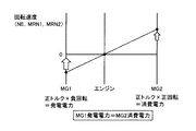
図2から図5の共線図を用いて、本実施の形態におけるエンジン始動制御の概要について説明する。上述のように、モータジェネレータ130,135およびエンジン160は、プラネタリギヤのサンギヤ、リングギヤ、およびプラネタリキャリアにそれぞれ結合される。
An outline of the engine start control in the present embodiment will be described using the alignment charts of FIGS. As described above,
蓄電装置110からの電力の授受ができず、かつエンジン160が停止した状態で、惰性により車両100が前進側に走行している場合を考える。この場合は、図2に示されるように、エンジン160の回転速度NEはゼロであり、モータジェネレータ135(MG2)の回転速度MRN2は正回転、そして、モータジェネレータ130(MG1)の回転速度MRN1は負回転の状態で釣り合った状態となっている。
Consider a case in which the
この状態から、図3に示すように、モータジェネレータ130に対して正トルクを与えるような制御信号PWI1が、ECU300から供給される。すなわち、モータジェネレータ130に発電動作を行なわせる。これによって、モータジェネレータ130の回転速度は低下しゼロに近づく。
From this state, as shown in FIG. 3, a control signal PWI <b> 1 that gives positive torque to
このとき、蓄電装置110への充電電力の供給ができないので、このままでは、モータジェネレータ130によって発電された電力によって、PCU120に含まれる機器が過電圧となるおそれがある。そのため、モータジェネレータ130と同様に、モータジェネレータ135に正トルクを与えるような制御信号PWI2が供給される。これによって、モータジェネレータ135によって、モータジェネレータ130によって発電された電力が消費され、エネルギバランスが維持される。
At this time, since charging power cannot be supplied to the
そうすると、図4のように、破線の直線W10が、実線の直線W20のように移行し、エンジン160の回転速度NEが上昇する。そして、エンジン160が始動可能な回転速度まで回転速度NEが上昇したところで、エンジン160のシリンダ内に燃料が噴射され、エンジン160が始動される。
Then, as shown in FIG. 4, the broken straight line W <b> 10 shifts to a solid straight line W <b> 20, and the rotational speed NE of the
エンジン160が始動されて自立運転状態となると、図5のように、モータジェネレータ130,135には、モータジェネレータ130による発電電力とモータジェネレータ135による消費電力がバランスするようにトルク指令値が設定され、その指令値に基づいた制御信号PWI1,PWI2がECU300から出力される。このようにすることによって、蓄電装置110からの電力の授受ができない状態であっても、発電電力と消費電力との収支が破綻することなく、また、モータジェネレータ130,135の回転速度を安定させながら、バッテリレス走行を行なうことが可能となる。
When
図6は、本実施の形態において、ECU300で実行されるエンジン始動制御を説明するための機能ブロック図である。図6の機能ブロック図に記載された各機能ブロックは、ECU300によるハードウェア的あるいはソフトウェア的な処理によって実現される。
FIG. 6 is a functional block diagram for illustrating engine start control executed by
図1および図6を参照して、ECU300は、判定部310と、モータ制御部320と、エンジン制御部330とを含む。
Referring to FIGS. 1 and 6,
判定部310は、ユーザ操作によるエンジン160の始動要求信号STと、蓄電装置110からの電力供給ができない異常が生じたことを示す故障信号FLRと、モータジェネレータ135の回転速度MRN2とを受ける。ここで、故障信号FLRは、たとえば、蓄電装置110の電圧VB,電流IBや、SMR115の状態によって判定される信号である。
判定部310は、これらの情報に基づいて、蓄電装置110からの電力供給が不可能であり、かつ、その状態でユーザによりエンジン160の始動操作がされたか否かを判定する。さらに判定部310は、モータジェネレータ135の回転速度MRN2に基づいて、車速が所定の速度以上であるか否かを判定する。
Based on these pieces of information,
そして、判定部310は、上記の条件が成立した場合には、始動要求フラグFLGをオンに設定して、モータ制御部320およびエンジン制御部330へ出力する。
Then, when the above condition is satisfied,
モータ制御部320は、判定部310からの始動要求フラグFLG、およびモータジェネレータ130,135の回転速度MRN1,MRN2を受ける。モータ制御部320は、始動要求フラグFLGがオンに設定された場合には、エンジン160の回転速度NEが始動可能な回転速度まで上昇し、かつ、モータジェネレータ130,135による電力収支がバランスするように、制御信号PWI1,PWI2を生成してインバータ122,123を制御する。また、モータ制御部320は、エンジン160の始動後においては、ユーザの操作に基づいて、必要とされる駆動力を出力しつつ、モータジェネレータ130,135の電力収支をバランスさせるようにインバータ122,123を制御する。
エンジン制御部330は、判定部310からの始動要求フラグFLG、およびエンジン160の回転速度NEを受ける。エンジン制御部330は、始動要求フラグFLGがオンに設定され、モータジェネレータ130,135によってエンジン160の回転速度NEが、始動可能な所定の回転速度に到達したことに応答して、燃料噴射量などの情報を含むエンジン160の制御信号DRVを出力し、エンジン160を始動させる。
エンジン160の始動が完了し自立運転が行なわれると、エンジン制御部330は、ユーザによるアクセルペダルの操作量などに基づいて、所望のトルクが出力されるようにエンジン160を制御する。
When the start of
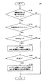
図7は、本実施の形態において、ECU300で実行されるエンジン始動制御処理の詳細を説明するためのフローチャートである。図7に示されるフローチャートは、ECU300に予め格納されたプログラムがメインルーチンから呼び出されて、所定周期で実行されることによって処理が実現される。あるいは、一部または全部のステップについては、専用のハードウェア(電子回路)で処理を実現することも可能である。
FIG. 7 is a flowchart for illustrating details of the engine start control process executed by
図1および図7を参照して、ECU300は、ステップ(以下、ステップをSと略す。)100にて、蓄電装置110からの電力供給が不能となる異常が生じているか否かを判定する。
Referring to FIGS. 1 and 7,
蓄電装置110からの電力供給が不能となる異常が生じていない場合(S100にてNO)は、蓄電装置110からの電力を用いてモータジェネレータ130,135を駆動することもできるし、モータジェネレータ130を用いてエンジン160を始動することも可能である。そのため、本制御を実行する必要はないので、ECU300は処理を終了し、メインルーチンに処理を戻す。
If there is no abnormality that disables power supply from power storage device 110 (NO in S100),
蓄電装置110からの電力供給が不能となる異常が生じている場合(S100にてYES)は、処理がS110に進められ、ECU300は、次にユーザによりエンジン160の始動要求がされているか(始動要求信号STがオンか)否かを判定する。
If there is an abnormality that disables power supply from power storage device 110 (YES in S100), the process proceeds to S110, and
エンジン160の始動要求がされていない場合(始動要求信号STがオフの場合)(S110にてNO)は、エンジン160を始動する必要はないので、ECU300は処理を終了し、メインルーチンに処理を戻す。
When
エンジン160の始動要求がされている場合(始動要求信号STがオフの場合)(S110にてNO)は、処理がS120に進められ、ECU300は、モータジェネレータ135の回転速度MRN2が所定の基準速度α以上であるか否かを判定することによって、車速が基準車速以上であるか否かを判定する。
When
回転速度MRN2が所定の基準速度αより小さい場合(S120にてNO)は、モータジェネレータ130,135を制御しても、始動可能なエンジン回転速度までエンジン160の回転速度NEを上昇させることができないため、ECU300は処理を終了し、メインルーチンに処理を戻す。
When rotation speed MRN2 is smaller than predetermined reference speed α (NO in S120), even if
回転速度MRN2が所定の基準速度α以上の場合(S120にてYES)は、S130に処理が進められ、モータジェネレータ130により発電させつつ、その発電電力をモータジェネレータ135により消費して反力をキャンセルさせながら、エンジン160の回転速度NEを上昇させる。そして、ECU300は、S140にて、エンジン160の回転速度NEが、始動が可能なしきい値β以上まで上昇したか否かを判定する。
If rotational speed MRN2 is equal to or higher than a predetermined reference speed α (YES in S120), the process proceeds to S130, and power is generated by
エンジン160の回転速度NEがしきい値βより小さい場合(S140にてNO)は、まだエンジン160の始動が行なえないので、ECU300は、メインルーチンの処理を戻して、回転速度NEがしきい値βに到達するのを待つ。
When engine speed NE is smaller than threshold value β (NO in S140),
そして、エンジン160の回転速度NEがしきい値β以上となった場合(S140にてYES)は、処理がS150に進められ、ECU300は、エンジン160を始動させるとともに、モータジェネレータ130による発電電力とモータジェネレータ135による消費電力との電力収支がバランスするように、バッテリレス制御を開始する。
If rotational speed NE of
以上のような処理に従って制御を行なうことによって、ハイブリッド車両において、蓄電装置からの電力供給ができない状態であっても、所定の車速を有している場合には、エンジンの始動を行なうことが可能となる。これによって、EV走行実施中に、蓄電装置からの電力が途絶する異常が発生した場合であっても、エンジンを始動して退避走行をすることが可能となる。 By performing the control according to the above-described processing, even if the hybrid vehicle is in a state where power cannot be supplied from the power storage device, the engine can be started if the vehicle has a predetermined vehicle speed. It becomes. Thus, even when an abnormality occurs in which the electric power from the power storage device is interrupted during the EV traveling, the engine can be started and the retreat traveling can be performed.
なお、上述の説明においては、2つのモータジェネレータを有する構成を例にして説明したが、駆動輪の回転力を用いて発電を行ない、エンジンの回転速度を上昇させることができる構成であれば、1つまたは3つ以上のモータジェネレータを有する構成であってもよい。ただし、モータジェネレータが1つの場合には、モータジェネレータによる発電電力によって機器が過電圧となることを防止するために、この発電電力を消費または蓄える機器(たとえば、抵抗やキャパシタ)を追加的に備えたり、補機負荷を用いて消費したりする必要があることに注意すべきである。また、モータジェネレータとエンジンとを結合する構成についても、プラネタリギヤの各ギヤに結合する対象を異なる態様としたり、クラッチ等の摩擦係合要素を介して結合したりするなどの様々な構成を採用することも可能である。 In the above description, the configuration having two motor generators has been described as an example. However, as long as the configuration can perform power generation using the rotational force of the drive wheels and increase the rotational speed of the engine, The configuration may include one or three or more motor generators. However, in the case of a single motor generator, in order to prevent the device from being overvoltaged by the power generated by the motor generator, a device (for example, a resistor or a capacitor) that consumes or stores this generated power may be additionally provided. It should be noted that it is necessary to consume with auxiliary load. In addition, as for the configuration for coupling the motor generator and the engine, various configurations are adopted such that the object to be coupled to each gear of the planetary gear is different, or is coupled through a friction engagement element such as a clutch. It is also possible.
今回開示された実施の形態はすべての点で例示であって制限的なものではないと考えられるべきである。本発明の範囲は上記した説明ではなく特許請求の範囲によって示され、特許請求の範囲と均等の意味および範囲内でのすべての変更が含まれることが意図される。 The embodiment disclosed this time should be considered as illustrative in all points and not restrictive. The scope of the present invention is defined by the terms of the claims, rather than the description above, and is intended to include any modifications within the scope and meaning equivalent to the terms of the claims.
100 車両、110 蓄電装置、115 SMR、120 PCU、121 コンバータ、122,123 インバータ、125 電動駆動部、130,135 モータジェネレータ、140 動力伝達ギヤ、150 駆動輪、160 エンジン、170,175 速度検出器、180 DC/DCコンバータ、190 補機負荷、195 補機バッテリ、300 ECU、310 判定部、320 モータ制御部、330 エンジン制御部、C1,C2 コンデンサ、NL1 接地線、PL1〜PL3 電力線。 100 vehicle, 110 power storage device, 115 SMR, 120 PCU, 121 converter, 122, 123 inverter, 125 electric drive unit, 130, 135 motor generator, 140 power transmission gear, 150 drive wheel, 160 engine, 170, 175 speed detector , 180 DC / DC converter, 190 auxiliary load, 195 auxiliary battery, 300 ECU, 310 determination unit, 320 motor control unit, 330 engine control unit, C1, C2 capacitor, NL1 ground line, PL1-PL3 power line.
Claims (5)
蓄電装置と、
内燃機関と、
前記蓄電装置からの電力を用いて前記車両の駆動力を生成するとともに、前記車両の駆動輪の回転力を用いて発電が可能な電動駆動部と、
前記内燃機関からの駆動力と前記電動駆動部からの駆動力とを協調的に制御して前記車両を走行させるように構成された制御装置とを備え、
前記制御装置は、前記蓄電装置からの電力を用いて前記電動駆動部を駆動することができず、かつ、車速が予め定められた基準車速を上回る状態において、前記内燃機関の始動要求を受けた場合は、前記電動駆動部において発電動作を行なわせることによって前記内燃機関の回転速度を上昇させて前記内燃機関を始動する、車両。 A vehicle,
A power storage device;
An internal combustion engine;
An electric drive unit that generates the driving force of the vehicle using electric power from the power storage device and that can generate electric power using the rotational force of the driving wheels of the vehicle;
A control device configured to cooperatively control the driving force from the internal combustion engine and the driving force from the electric drive unit to travel the vehicle;
The control device receives a request to start the internal combustion engine in a state where the electric drive unit cannot be driven using electric power from the power storage device and the vehicle speed exceeds a predetermined reference vehicle speed. In this case, the vehicle starts the internal combustion engine by increasing the rotational speed of the internal combustion engine by causing the electric drive section to perform a power generation operation.
前記車両の駆動輪の回転力を用いて発電が可能な第1の回転電機と、
前記蓄電装置からの電力を用いて前記車両の駆動力を生成することが可能な第2の回転電機とを含み、
前記制御装置は、前記蓄電装置からの電力を用いて前記第1および第2の回転電機を駆動することができず、かつ、前記車速が前記基準車速を上回る状態において、前記始動要求を受けた場合は、前記第1の回転電機において発電動作を行なわせることによって前記内燃機関の回転速度を上昇させて前記内燃機関を始動する、請求項1に記載の車両。 The electric drive unit is
A first rotating electric machine capable of generating electric power using the rotational force of the driving wheel of the vehicle;
A second rotating electrical machine capable of generating a driving force of the vehicle using electric power from the power storage device,
The control device receives the start request in a state where the first and second rotating electric machines cannot be driven using electric power from the power storage device and the vehicle speed exceeds the reference vehicle speed. 2. The vehicle according to claim 1, wherein the first rotating electrical machine is caused to perform a power generation operation to increase the rotational speed of the internal combustion engine to start the internal combustion engine.
前記車両は、
蓄電装置と、
内燃機関と、
前記蓄電装置からの電力を用いて前記車両の駆動力を生成するとともに、前記車両の駆動輪の回転力を用いて発電が可能な回転電機とを含み、
前記車両は、前記内燃機関からの駆動力と前記回転電機からの駆動力とが協調的に制御されることにより走行し、
前記制御方法は、
前記蓄電装置からの電力を用いて前記回転電機を駆動することができるか否かを判定するステップと、
車速が予め定められた基準車速を上回るか否かを判定するステップと、
前記蓄電装置からの電力を用いて前記回転電機を駆動することができず、かつ、前記車速が前記基準車速を上回る状態において、前記内燃機関の始動要求を受けた場合に、前記回転電機において発電動作を行なわせるステップと、
前記内燃機関の回転速度が予め定められたしきい値を上回った場合に、燃料噴射を開始して前記内燃機関を始動するステップとを備える、車両の制御方法。 A vehicle control method comprising:
The vehicle is
A power storage device;
An internal combustion engine;
A rotating electrical machine capable of generating driving force of the vehicle using electric power from the power storage device and generating electric power using rotational force of driving wheels of the vehicle,
The vehicle travels by cooperatively controlling the driving force from the internal combustion engine and the driving force from the rotating electrical machine,
The control method is:
Determining whether the rotating electrical machine can be driven using electric power from the power storage device; and
Determining whether the vehicle speed exceeds a predetermined reference vehicle speed;
When the rotating electrical machine cannot be driven using the electric power from the power storage device, and the vehicle speed exceeds the reference vehicle speed, and the start request for the internal combustion engine is received, the rotating electrical machine generates power. A step to perform the action;
And a step of starting fuel injection and starting the internal combustion engine when the rotational speed of the internal combustion engine exceeds a predetermined threshold value.
Priority Applications (2)
| Application Number | Priority Date | Filing Date | Title |
|---|---|---|---|
| JP2011043964A JP2012180004A (en) | 2011-03-01 | 2011-03-01 | Vehicle and control method for vehicle |
| US13/404,300 US20120226401A1 (en) | 2011-03-01 | 2012-02-24 | Vehicle and control apparatus for vehicle |
Applications Claiming Priority (1)
| Application Number | Priority Date | Filing Date | Title |
|---|---|---|---|
| JP2011043964A JP2012180004A (en) | 2011-03-01 | 2011-03-01 | Vehicle and control method for vehicle |
Publications (1)
| Publication Number | Publication Date |
|---|---|
| JP2012180004A true JP2012180004A (en) | 2012-09-20 |
Family
ID=46753795
Family Applications (1)
| Application Number | Title | Priority Date | Filing Date |
|---|---|---|---|
| JP2011043964A Pending JP2012180004A (en) | 2011-03-01 | 2011-03-01 | Vehicle and control method for vehicle |
Country Status (2)
| Country | Link |
|---|---|
| US (1) | US20120226401A1 (en) |
| JP (1) | JP2012180004A (en) |
Cited By (3)
| Publication number | Priority date | Publication date | Assignee | Title |
|---|---|---|---|---|
| JP2014151695A (en) * | 2013-02-06 | 2014-08-25 | Toyota Motor Corp | Vehicle |
| JP2015147513A (en) * | 2014-02-06 | 2015-08-20 | 株式会社デンソー | hybrid vehicle |
| JP2017040246A (en) * | 2015-08-21 | 2017-02-23 | 株式会社デンソー | Control device of vehicle |
Families Citing this family (28)
| Publication number | Priority date | Publication date | Assignee | Title |
|---|---|---|---|---|
| US9114804B1 (en) | 2013-03-14 | 2015-08-25 | Oshkosh Defense, Llc | Vehicle drive and method with electromechanical variable transmission |
| CN104143821B (en) * | 2013-08-23 | 2017-03-22 | 南京师范大学 | Regenerative bleeder resistor protection method |
| SE537897C2 (en) | 2014-03-20 | 2015-11-17 | Scania Cv Ab | Procedure for driving a vehicle with a hybrid drivetrain, vehicles with such a hybrid drivetrain, computer programs for controlling a vehicle's driving, and a computer software product comprising program code |
| SE539030C2 (en) | 2014-03-20 | 2017-03-21 | Scania Cv Ab | A method for controlling a hybrid driver, vehicles with such a hybrid driver, computer programs for controlling such a hybrid driver, and a computer software product comprising program code |
| SE539661C2 (en) | 2014-03-20 | 2017-10-24 | Scania Cv Ab | Method for starting an internal combustion engine of a hybrid drive line, vehicles with such an internal combustion engine, computer programs for starting such an internal combustion engine, and a computer program product comprising program code |
| SE538736C2 (en) | 2014-03-20 | 2016-11-08 | Scania Cv Ab | A method of controlling a hybrid drive line to optimize the driving torque of an internal combustion engine arranged at the hybrid drive line |
| SE538735C2 (en) | 2014-03-20 | 2016-11-08 | Scania Cv Ab | Procedure for controlling a hybrid drive line to optimize fuel consumption |
| SE539002C2 (en) | 2014-03-20 | 2017-03-14 | Scania Cv Ab | A method for controlling a hybrid driver, vehicles with such a hybrid driver, computer programs for controlling such a hybrid driver, and a computer software product comprising program code |
| SE538187C2 (en) | 2014-03-20 | 2016-03-29 | Scania Cv Ab | A method for controlling a hybrid driver, vehicles with such a hybrid driver, computer programs for controlling such a hybrid driver, and a computer software product comprising program code |
| SE539660C2 (en) | 2014-03-20 | 2017-10-24 | Scania Cv Ab | Method of starting an internal combustion engine in a hybrid drive line, vehicles with such a hybrid drive line, computer programs for starting an internal combustion engine, and a computer program product including program code |
| SE539662C2 (en) | 2014-03-20 | 2017-10-24 | Scania Cv Ab | Method of starting an internal combustion engine in a hybrid drive line, vehicles with such a hybrid drive line, computer programs for starting an internal combustion engine, and a computer program product including program code |
| SE540693C2 (en) | 2014-03-20 | 2018-10-09 | Scania Cv Ab | A method for controlling a hybrid driver, vehicles with such a hybrid driver, computer programs for controlling such a hybrid driver, and a computer software product comprising program code |
| SE539032C2 (en) | 2014-03-20 | 2017-03-21 | Scania Cv Ab | A method for controlling a hybrid driver, vehicles with such a hybrid driver, computer programs for controlling such a hybrid driver, and a computer software product comprising program code |
| SE540692C2 (en) | 2014-03-20 | 2018-10-09 | Scania Cv Ab | A method for controlling a hybrid driver, vehicles with such a hybrid driver, computer programs for controlling such a hybrid driver, and a computer software product comprising program code |
| SE537896C2 (en) | 2014-03-20 | 2015-11-17 | Scania Cv Ab | Method of starting an internal combustion engine in a hybrid drive line, vehicles with such a hybrid drive line, computer programs for starting an internal combustion engine, and a computer program product comprising program code |
| SE539028C2 (en) * | 2014-03-20 | 2017-03-21 | Scania Cv Ab | Procedure for driving a vehicle with a hybrid drivetrain, vehicles with such a hybrid drivetrain, computer programs for controlling a vehicle's driving, and a computer software product comprising program code |
| SE538737C2 (en) | 2014-03-20 | 2016-11-08 | Scania Cv Ab | A method for controlling a hybrid driver, vehicles with such a hybrid driver, a computer program for controlling a hybrid driver, and a computer software product comprising program code |
| WO2016016899A1 (en) | 2014-07-30 | 2016-02-04 | Mitraltech Ltd. | Articulatable prosthetic valve |
| US9651120B2 (en) | 2015-02-17 | 2017-05-16 | Oshkosh Corporation | Multi-mode electromechanical variable transmission |
| US10584775B2 (en) | 2015-02-17 | 2020-03-10 | Oshkosh Corporation | Inline electromechanical variable transmission system |
| US10578195B2 (en) | 2015-02-17 | 2020-03-03 | Oshkosh Corporation | Inline electromechanical variable transmission system |
| US10421350B2 (en) | 2015-10-20 | 2019-09-24 | Oshkosh Corporation | Inline electromechanical variable transmission system |
| US10982736B2 (en) | 2015-02-17 | 2021-04-20 | Oshkosh Corporation | Multi-mode electromechanical variable transmission |
| US9650032B2 (en) | 2015-02-17 | 2017-05-16 | Oshkosh Corporation | Multi-mode electromechanical variable transmission |
| US9656659B2 (en) | 2015-02-17 | 2017-05-23 | Oshkosh Corporation | Multi-mode electromechanical variable transmission |
| US11701959B2 (en) | 2015-02-17 | 2023-07-18 | Oshkosh Corporation | Inline electromechanical variable transmission system |
| JP6315016B2 (en) * | 2016-03-25 | 2018-04-25 | トヨタ自動車株式会社 | Control device for hybrid vehicle |
| WO2019069458A1 (en) * | 2017-10-06 | 2019-04-11 | 株式会社 東芝 | Hybrid vehicle |
Citations (2)
| Publication number | Priority date | Publication date | Assignee | Title |
|---|---|---|---|---|
| JP2009184559A (en) * | 2008-02-07 | 2009-08-20 | Toyota Motor Corp | Vehicle, drive unit, and control method for vehicle |
| JP2010083427A (en) * | 2008-10-02 | 2010-04-15 | Toyota Motor Corp | Vehicle control apparatus and control method |
-
2011
- 2011-03-01 JP JP2011043964A patent/JP2012180004A/en active Pending
-
2012
- 2012-02-24 US US13/404,300 patent/US20120226401A1/en not_active Abandoned
Patent Citations (2)
| Publication number | Priority date | Publication date | Assignee | Title |
|---|---|---|---|---|
| JP2009184559A (en) * | 2008-02-07 | 2009-08-20 | Toyota Motor Corp | Vehicle, drive unit, and control method for vehicle |
| JP2010083427A (en) * | 2008-10-02 | 2010-04-15 | Toyota Motor Corp | Vehicle control apparatus and control method |
Cited By (4)
| Publication number | Priority date | Publication date | Assignee | Title |
|---|---|---|---|---|
| JP2014151695A (en) * | 2013-02-06 | 2014-08-25 | Toyota Motor Corp | Vehicle |
| JP2015147513A (en) * | 2014-02-06 | 2015-08-20 | 株式会社デンソー | hybrid vehicle |
| JP2017040246A (en) * | 2015-08-21 | 2017-02-23 | 株式会社デンソー | Control device of vehicle |
| WO2017033354A1 (en) * | 2015-08-21 | 2017-03-02 | 株式会社デンソー | Vehicle control device |
Also Published As
| Publication number | Publication date |
|---|---|
| US20120226401A1 (en) | 2012-09-06 |
Similar Documents
| Publication | Publication Date | Title |
|---|---|---|
| JP2012180004A (en) | Vehicle and control method for vehicle | |
| JP5655868B2 (en) | Vehicle and vehicle control method | |
| JP5370584B2 (en) | Hybrid vehicle | |
| JP5093293B2 (en) | Vehicle control device | |
| WO2013051104A1 (en) | Electrical charging control apparatus and electrical charging method | |
| JP6149806B2 (en) | Hybrid vehicle | |
| JP5747724B2 (en) | Vehicle and vehicle control method | |
| JP5811107B2 (en) | Hybrid vehicle control device, hybrid vehicle including the same, and hybrid vehicle control method | |
| JP2015209153A (en) | Hybrid vehicle and control method therefor | |
| JP5598555B2 (en) | Vehicle and vehicle control method | |
| JP5729475B2 (en) | Vehicle and vehicle control method | |
| JP2013099994A (en) | Vehicle and method of controlling the same | |
| JP2010064499A (en) | Hybrid vehicle | |
| JP2014184880A (en) | Vehicle and control unit of vehicle | |
| US9199542B2 (en) | Vehicle and method of controlling vehicle | |
| JP2015057009A (en) | Vehicle | |
| JP6404548B2 (en) | vehicle | |
| EP2762374B1 (en) | Vehicle and control method for vehicle | |
| JPWO2014064794A1 (en) | Electric vehicle | |
| JP2010208541A (en) | Control device of hybrid vehicle, control method, and hybrid vehicle | |
| JP5712941B2 (en) | Vehicle and vehicle control method | |
| JP2007210413A (en) | Power output device, vehicle mounted therewith, and control method for power output device | |
| EP2762375A1 (en) | Vehicle and control method for vehicle | |
| JP6361299B2 (en) | Hybrid vehicle | |
| JP2015016715A (en) | Hybrid vehicle and control method for hybrid vehicle |
Legal Events
| Date | Code | Title | Description |
|---|---|---|---|
| A131 | Notification of reasons for refusal |
Free format text: JAPANESE INTERMEDIATE CODE: A131 Effective date: 20121023 |
|
| A02 | Decision of refusal |
Free format text: JAPANESE INTERMEDIATE CODE: A02 Effective date: 20130305 |