EP3119300B1 - Intramedullary device with compound fastener trajectories - Google Patents
Intramedullary device with compound fastener trajectories Download PDFInfo
- Publication number
- EP3119300B1 EP3119300B1 EP15721362.0A EP15721362A EP3119300B1 EP 3119300 B1 EP3119300 B1 EP 3119300B1 EP 15721362 A EP15721362 A EP 15721362A EP 3119300 B1 EP3119300 B1 EP 3119300B1
- Authority
- EP
- European Patent Office
- Prior art keywords
- bore
- longitudinal axis
- bores
- intramedullary device
- opening
- Prior art date
- Legal status (The legal status is an assumption and is not a legal conclusion. Google has not performed a legal analysis and makes no representation as to the accuracy of the status listed.)
- Active
Links
Images


Classifications
-
- A—HUMAN NECESSITIES
- A61—MEDICAL OR VETERINARY SCIENCE; HYGIENE
- A61B—DIAGNOSIS; SURGERY; IDENTIFICATION
- A61B17/00—Surgical instruments, devices or methods
- A61B17/56—Surgical instruments or methods for treatment of bones or joints; Devices specially adapted therefor
- A61B17/58—Surgical instruments or methods for treatment of bones or joints; Devices specially adapted therefor for osteosynthesis, e.g. bone plates, screws or setting implements
- A61B17/68—Internal fixation devices, including fasteners and spinal fixators, even if a part thereof projects from the skin
- A61B17/72—Intramedullary devices, e.g. pins or nails
- A61B17/7233—Intramedullary devices, e.g. pins or nails with special means of locking the nail to the bone
-
- A—HUMAN NECESSITIES
- A61—MEDICAL OR VETERINARY SCIENCE; HYGIENE
- A61B—DIAGNOSIS; SURGERY; IDENTIFICATION
- A61B17/00—Surgical instruments, devices or methods
- A61B17/56—Surgical instruments or methods for treatment of bones or joints; Devices specially adapted therefor
- A61B17/58—Surgical instruments or methods for treatment of bones or joints; Devices specially adapted therefor for osteosynthesis, e.g. bone plates, screws or setting implements
- A61B17/68—Internal fixation devices, including fasteners and spinal fixators, even if a part thereof projects from the skin
- A61B17/72—Intramedullary devices, e.g. pins or nails
-
- A—HUMAN NECESSITIES
- A61—MEDICAL OR VETERINARY SCIENCE; HYGIENE
- A61B—DIAGNOSIS; SURGERY; IDENTIFICATION
- A61B17/00—Surgical instruments, devices or methods
- A61B17/56—Surgical instruments or methods for treatment of bones or joints; Devices specially adapted therefor
- A61B2017/564—Methods for bone or joint treatment
Definitions
- the present disclosure relates to an intramedullary device, and more particularly to an intramedullary fixation device with compound trajectories.
- Intramedullary fixation devices may include a cannulated or non-cannulated tubular body.
- the tubular body may include a plurality of through-bores disposed at various angles relative to each other, in order to obtain angular stability, improve retention within the bone, and optimize the placement of the intramedullary fixation device within the bone. Screws, or other bone fixation devices, may be placed within the through-bores to secure the intramedullary fixation device within the bone.
- US 2006/0111716 and US 2012/0143192 disclose intramedullary nails with through holes.
- the present invention provides an intramedullary device as defined by claim 1. Preferred embodiments are defined by the dependent claims.
- the intramedullary device 10 may be a rod-like member having a substantially cylindrical construct extending from a proximal end 18 to a distal end 20 along a longitudinal axis 21.
- the proximal end 18 may be a driving end.
- a force may be applied to the proximal end 18 of the device 10, via a hammer, mallet, or other suitable driving apparatus (not shown), for securing the device 10 within the bone 12.
- the distal end 20 may be a driving end.
- the longitudinal axis 21 may extend in a direction substantially parallel to the X-axis.
- the longitudinal axis 21 of the device 10 may be substantially aligned with the longitudinal axis 14 of the bone 12.
- the intramedullary device 10 may include a cylindrical cavity 22 extending between the proximal end 18 and the distal end 20 along the longitudinal axis 21, such that the device 10 defines a generally cannulated construct along a substantial portion or an entirety of the device. It will also be appreciated that in other configurations, the intramedullary device 10, or portions thereof, may be a substantially solid construct.
- the device 10 may include a plurality of bores 24 disposed at multiple or compound angles and/or trajectories in a first region 11 a of the device 10.
- the device 10 may include a first bore 24a, a second bore 24b, a third bore 24c, a fourth bore 24d, and a fifth bore 24e.
- the bores 24a-24e may be disposed generally in the distal end 20 of the device 10.
- At least one of the bores 24a-24e may be a threaded bore, operable to receive and mate with a threaded fastener.
- the cavity 22 and the first through fifth bores 24a-24e may be disposed in the intramedullary device 10 such that the cavity 22 is in communication with, or otherwise opens into, each of the bores 24a-24e.
- the first and second bores 24a, 24b may define longitudinal axes 26a, 26b, respectively.
- the first and second bores 24a, 24b may extend radially through the device 10 such that the longitudinal axes 26a, 26b are substantially perpendicular to the longitudinal axis 21 of the device 10, and generally parallel to the Z-axis.
- the first bore 24a includes a substantially circular cross section
- the second bore 24b includes an oblong or oval cross section.
- the oblong or oval cross section of the second bore 24b allows the user to vary an angle ⁇ formed by the longitudinal axis 21 of the device 10 and a longitudinal axis 28 of the fastener 16a.
- the oblong or oval cross section of the second bore 24b also allows the user to vary a distance between the fastener 16a and the distal end 20 of the device 10. It will also be appreciated that the cross-sectional area of the first and second bores 24a, 24b may include other shapes within the scope of the present disclosure.
- the third bore 24c may define a longitudinal axis 26c.
- the third bore 24c may extend through the device 10 such that the axis 26c is substantially perpendicular to the longitudinal axis 21 of the device 10, and substantially perpendicular to the longitudinal axes 26a, 26b of the first and second bores 24a, 24b, respectively.
- the axis 26c may extend in a direction generally parallel to the Y-axis, as illustrated in Figure 2A .
- the third bore 24c includes an oblong or oval cross section.
- the oblong or oval cross section of the third bore 24c allows the user to vary an angle ⁇ formed by the longitudinal axis 21 of the device 10 and a longitudinal axis 30 of the fastener 16c.
- the oblong or oval cross section of the third bore 24c also allows the user to vary a distance between the fastener 16c and the distal end 20 of the device 10. It will also be appreciated that the cross-sectional area of the third bore 24c may include other shapes within the scope of the present disclosure.
- the fourth and fifth bores 24d, 24e may be located between the second and third bores 24b, 24c ( Figure 2A ). In another configuration, the fourth and fifth bores 24d, 24e may be located between the second bore 24c and the distal end 20 of the intramedullary device 10 ( Figure 2B ). In other configurations, the fourth and fifth bores 24d, 24e may be located in other positions with respect to the first, second and third bores 24a-24c.
- the fourth and fifth bores 24d, 24e may define longitudinal axes 26d, 26e, respectively.
- the fourth and fifth bores 24d, 24e may extend through the device 10 such that the longitudinal axes 26d, 26e are substantially perpendicular to the X-Z plane.
- the fourth and fifth bores 24d, 24e may extend in the X-Y plane.
- the axes 26d, 26e may form angles ⁇ d, ⁇ e, respectively, relative to the longitudinal axis 21 of the device 10.
- the angle ⁇ d may be between forty degrees and sixty degrees.
- the angle ⁇ e may be between one hundred twenty degrees and one hundred sixty degrees. In one configuration, the angle ⁇ d may be substantially equal to forty-five degrees (45o) and the angle ⁇ e may be substantially equal to one hundred thirty-five degrees (135o).
- the fourth and fifth bores 24d, 24e may extend through the device such that the fourth bore 24d includes a first opening 34 and a second opening 36, and the fifth bore 24e includes the first opening 34 and a third opening 38.
- a fastener 16d may be inserted through the fourth bore 24d such that a head 40 of the fastener 16d is disposed at, or extends from, the second opening 36 and a stem 42 of the fastener 16d extends from the first opening 34.
- the fastener 16d may be inserted through the fifth bore 24e such that the head 40 of the fastener 16d is disposed at, or extends from, the third opening 38 and the stem 42 of the fastener 16d extends from the first opening 34.
- the fastener 16d may be disposed within the fourth or fifth bores 24d, 24e, respectively, such that the head 40 of the fastener 16d is disposed at, or extends from, the first opening 34, and the stem 42 of the fastener 16d extends from the second opening or third opening 36, 38. Accordingly, it will be appreciated that the configuration of the bores 24d, 24e, including the first opening 34 and the angles ⁇ d, ⁇ e, may improve the interchangeability of the intramedullary device 10 with respect to multiple bones 12 (e.g., a left femur and a right femur).
- the configuration of the fourth and fifth bores 24d, 24e, including the first opening 34 and the angles ⁇ d, ⁇ e, can allow for fewer openings or holes in the intramedullary device 10, and can thus improve the strength and integrity of the intramedullary device 10.
- the first opening 34 may have a substantially circular or oval shape. It will be appreciated, however, that the first opening 34 may have other shapes, including a figure eight shape, within the scope of the present disclosure.
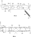
- the intramedullary device 10 may also include a sixth bore 24f, a seventh bore 24g, an eighth bore 24h, and a ninth bore 24i.
- the bores 24f-24i may be disposed in a second region 11b of the device 10, generally opposite the first region 11a of the device.
- the first region 11a may include the distal end 20 and the second region 11b may include the proximal end 18.
- a mid region 11c may extend from and between the first and second regions 11a, 11b, and may include one or more additional fasteners 16.
- At least one of the bores 24f-24i may be a threaded bore, operable to receive and mate with a threaded fastener.
- the intramedullary devices 10 may include any combination of the first through ninth bores 24a-24i.
- the cylindrical cavity 22 and the sixth through ninth bores 24f-24i may be disposed in the intramedullary device 10 such that the cylindrical cavity 22 is in communication with, or otherwise opens into, each of the bores 24f-24i.
- the sixth and seventh bores 24f, 24g may define longitudinal axes 26f, 26g, respectively.
- the sixth and seventh bores 24f, 24g may extend through the device 10 such that the longitudinal axes 26f, 26g are substantially perpendicular to the longitudinal axis 21 of the device 10, and generally parallel to the Y-axis, as illustrated in Figure 5 .
- the longitudinal axes 26f, 26g may be oriented in the X-Y plane.
- the sixth and seventh bores 24f, 24g may include a substantially circular cross section. It will be appreciated, however, that the sixth and seventh bores 24f, 24g may include other cross sections (e.g., an oblong or oval cross section) within the scope of the present disclosure.
- the eighth and ninth bores 24h, 24i may be located between the sixth and seventh bores 24f, 24g. In another configuration, the eighth and ninth bores 24h, 24i may be located between the seventh bore 24g and the distal end 20 of the intramedullary device 10. In other configurations, the eighth and ninth bores 24h, 24i may be located in other positions with respect to the sixth and seventh bores 24f, 24g.
- the eighth and ninth bores 24h, 24i may define longitudinal axes 26h, 26i, respectively.
- the eighth and ninth bores 24h, 24i may extend through the device 10 such that the longitudinal axes 26h, 26i define an angle ⁇ therebetween, and further define angles ⁇ h, ⁇ i, respectively, relative to the X-Y plane.
- the angle ⁇ may be between fifteen degrees and seventy-five degrees. In one configuration, the angle ⁇ may be substantially equal to forty-five degrees.
- the angles ⁇ h, ⁇ i may be between five degrees and forty degrees. In one configuration, the angle ⁇ h may be substantially equal to ten degrees and the angle ⁇ i may be substantially equal to eighty degrees.
- the longitudinal axes 26h, 26i may be non-coplanar.
- the eighth and ninth axes 24h, 24i also define angles ⁇ h, ⁇ i, respectively, relative to the longitudinal axis 21 of the device.
- the angles ⁇ h, ⁇ i may be between fifteen degrees and seventy-five degrees. In one configuration the angles ⁇ h, ⁇ i may be substantially equal to forty-five degrees.
- the configuration of the angles ⁇ h, ⁇ i and ⁇ h, ⁇ i may be such that the eighth bore 24h includes a first opening 50 and a second opening 52, and the ninth bore 24i includes the first opening 50 and a third opening 54. As shown in Figure 6 , the first opening 50 may have a substantially "8"-shaped profile.
- the first opening 50 may define a perimeter including a first lobe portion 50a and a second lobe portion 50b that collectively form a figure eight shape.
- the first and second lobe portions 50a, 50b may each define substantially circular or oval portions, depending on the desired angles for the fasteners 16.
- a fastener 16h may be inserted through the eighth bore 24h such that a head 56 of the fastener 16h is disposed at, or extends from, the first lobe 50a of the first opening 50, and a stem (not shown) of the fastener 16h extends from the second opening 52.
- a fastener 16i may be inserted through the ninth bore 24i such that a head 60 of the fastener 16i is disposed at, or extends from, the second lobe 50b of the first opening 50, and a stem 62 of the fastener 16i extends from the third opening 54.
- the fasteners 16h and 16i may be disposed within the eighth and ninth bores 24h, 24i, respectively, such that the head 56 of the fastener 16h is disposed at, or extends from, the second opening 52 and/or the head 60 of the fastener 16i is disposed at, or extends from, the third opening 54. Accordingly, it will be appreciated that the configuration of the bores 24h, 24i, including the first opening 50 and the angles ⁇ h, ⁇ i and ⁇ h, ⁇ i, may improve the interchangeability of the intramedullary device 10 with respect to multiple bones (e.g., a left tibia and a right tibia).
- Example embodiments are provided so that this disclosure will be thorough, and will fully convey the scope to those who are skilled in the art. Numerous specific details are set forth such as examples of specific components, devices, and methods, to provide a thorough understanding of embodiments of the present disclosure. It will be apparent to those skilled in the art that specific details need not be employed, that example embodiments may be embodied in many different forms and that neither should be construed to limit the scope of the disclosure. In some example embodiments, well-known processes, well-known device structures, and well-known technologies are not described in detail.
- first, second, third, etc. may be used herein to describe various elements, components, regions, layers and/or sections, these elements, components, regions, layers and/or sections should not be limited by these terms. These terms may be only used to distinguish one element, component, region, layer or section from another region, layer or section. Terms such as “first,” “second,” and other numerical terms when used herein do not imply a sequence or order unless clearly indicated by the context. Thus, a first element, component, region, layer or section discussed below could be termed a second element, component, region, layer or section without departing from the teachings of the example embodiments.
- spatially relative terms such as “inner,” “outer,” “beneath,” “below,” “lower,” “above,” “upper,” and the like, may be used herein for ease of description to describe one element or feature's relationship to another element(s) or feature(s) as illustrated in the figures.
- Spatially relative terms may be intended to encompass different orientations of the device in use or operation in addition to the orientation depicted in the figures. For example, if the device in the figures is turned over, elements described as “below” or “beneath” other elements or features would then be oriented “above” the other elements or features.
- the example term “below” can encompass both an orientation of above and below.
- the device may be otherwise oriented (rotated 90 degrees or at other orientations) and the spatially relative descriptors used herein interpreted accordingly.
Landscapes
- Health & Medical Sciences (AREA)
- Orthopedic Medicine & Surgery (AREA)
- Surgery (AREA)
- Life Sciences & Earth Sciences (AREA)
- Heart & Thoracic Surgery (AREA)
- Nuclear Medicine, Radiotherapy & Molecular Imaging (AREA)
- Engineering & Computer Science (AREA)
- Biomedical Technology (AREA)
- Neurology (AREA)
- Medical Informatics (AREA)
- Molecular Biology (AREA)
- Animal Behavior & Ethology (AREA)
- General Health & Medical Sciences (AREA)
- Public Health (AREA)
- Veterinary Medicine (AREA)
- Surgical Instruments (AREA)
Applications Claiming Priority (3)
| Application Number | Priority Date | Filing Date | Title |
|---|---|---|---|
| US201461968636P | 2014-03-21 | 2014-03-21 | |
| US14/568,535 US9839454B2 (en) | 2014-03-21 | 2014-12-12 | Intramedullary device with compound fastener trajectories |
| PCT/US2015/021393 WO2015143112A1 (en) | 2014-03-21 | 2015-03-19 | Intramedullary device with compound fastener trajectories |
Publications (2)
| Publication Number | Publication Date |
|---|---|
| EP3119300A1 EP3119300A1 (en) | 2017-01-25 |
| EP3119300B1 true EP3119300B1 (en) | 2019-12-04 |
Family
ID=54140964
Family Applications (1)
| Application Number | Title | Priority Date | Filing Date |
|---|---|---|---|
| EP15721362.0A Active EP3119300B1 (en) | 2014-03-21 | 2015-03-19 | Intramedullary device with compound fastener trajectories |
Country Status (7)
Families Citing this family (16)
| Publication number | Priority date | Publication date | Assignee | Title |
|---|---|---|---|---|
| EP2667808B1 (en) * | 2011-01-26 | 2015-08-26 | Del Palma Orthopedics, LLC | Lower extremity fusion devices |
| DE102013005414A1 (de) * | 2013-03-28 | 2014-10-02 | Dietmar Wolter | Osteosynthesesystem für die multidirektionale, winkelstabile Versorgung von Frakturen von Röhrenknochen umfassend einen Marknagel und Knochenschrauben |
| US9839454B2 (en) | 2014-03-21 | 2017-12-12 | Biomet C.V. | Intramedullary device with compound fastener trajectories |
| US20220151664A1 (en) * | 2015-04-16 | 2022-05-19 | Texas Tech University System | Ankle (Tibio-Talar) Fusion Nail |
| KR101722252B1 (ko) * | 2016-03-18 | 2017-04-03 | 이동훈 | 틸팅 방지 기능을 갖는 골수강 네일 |
| US11083503B2 (en) | 2016-09-22 | 2021-08-10 | Globus Medical, Inc. | Systems and methods for intramedullary nail implantation |
| US10751096B2 (en) | 2016-09-22 | 2020-08-25 | Bala Sundararajan | Systems and methods for intramedullary nail implantation |
| US11045242B2 (en) | 2016-09-22 | 2021-06-29 | Globus Medical, Inc. | Systems and methods for intramedullary nail implantation |
| US10492803B2 (en) | 2016-09-22 | 2019-12-03 | Globus Medical, Inc. | Systems and methods for intramedullary nail implantation |
| US10299847B2 (en) | 2016-09-22 | 2019-05-28 | Globus Medical, Inc. | Systems and methods for intramedullary nail implantation |
| EP3466357B1 (en) * | 2017-10-09 | 2022-01-05 | Globus Medical, Inc. | Systems intramedullary nail implantation |
| US11000327B2 (en) | 2018-12-14 | 2021-05-11 | Nextremity Solutions, Inc. | Bone defect repair apparatus and method |
| US10987146B2 (en) | 2019-03-05 | 2021-04-27 | Nextremity Solutions, Inc. | Bone defect repair apparatus and method |
| US11633219B2 (en) | 2019-06-26 | 2023-04-25 | Globus Medical, Inc. | Fenestrated pedicle nail |
| US12004785B2 (en) | 2022-04-21 | 2024-06-11 | DePuy Synthes Products, Inc. | Retrograde femoral intramedullary nail, and related systems and methods |
| JP2025516517A (ja) * | 2022-05-20 | 2025-05-30 | スミス アンド ネフュー インコーポレイテッド | 可変角度ねじ開口部を備えた髄内脛骨用釘 |
Family Cites Families (20)
| Publication number | Priority date | Publication date | Assignee | Title |
|---|---|---|---|---|
| US4622959A (en) * | 1985-03-05 | 1986-11-18 | Marcus Randall E | Multi-use femoral intramedullary nail |
| DE4318150C2 (de) * | 1993-06-01 | 1996-08-01 | Endocare Ag | Osteosynthese-Hilfsmittel zur Versorgung subtrochanterer und pertrochanterer Frakturen sowie von Schenkelhalsfrakturen |
| US5549610A (en) | 1994-10-31 | 1996-08-27 | Smith & Nephew Richards Inc. | Femoral intramedullary nail |
| US5658288A (en) * | 1996-03-19 | 1997-08-19 | Kim; Andrew C. | Universal dynamic compression device for intramedullary system |
| JP2003022137A (ja) * | 2001-07-05 | 2003-01-24 | Alps Electric Co Ltd | 力覚発生入力装置 |
| US20030069581A1 (en) * | 2001-10-04 | 2003-04-10 | Stinson David T. | Universal intramedullary nails, systems and methods of use thereof |
| US20060149257A1 (en) * | 2002-05-30 | 2006-07-06 | Orbay Jorge L | Fracture fixation device |
| US7001386B2 (en) * | 2002-07-23 | 2006-02-21 | Advanced Orthopaedic Solutions, Inc. | Intramedullary nail for long bone fractures |
| DE20213166U1 (de) * | 2002-08-28 | 2004-01-08 | Stryker Trauma Gmbh | Humerusnagel |
| KR100987550B1 (ko) | 2003-03-21 | 2010-10-12 | 신세스 게엠바하 | 골수내 네일 |
| EP1830727B1 (de) * | 2004-12-31 | 2012-08-29 | Synthes GmbH | Marknagel |
| FR2885513B1 (fr) * | 2005-05-13 | 2007-08-10 | Newdeal S A S Soc Par Actions | Appareillage d'arthrodese pour une articulation, du genre articulation de la cheville, et clou d'athrodese destine a etre utilise dans un tel appareillage |
| GB2445346B (en) * | 2005-10-21 | 2011-03-09 | Acumed Llc | Orthopedic rod with locking aperture |
| US9320551B2 (en) * | 2007-01-26 | 2016-04-26 | Biomet Manufacturing, Llc | Lockable intramedullary fixation device |
| US9308031B2 (en) * | 2007-01-26 | 2016-04-12 | Biomet Manufacturing, Llc | Lockable intramedullary fixation device |
| US8157803B1 (en) * | 2007-08-21 | 2012-04-17 | Surgical Implant Generation Network | Bone fixation using an intramedullary nail interlocked with a buttress member |
| CN105726112B (zh) * | 2009-06-30 | 2021-04-27 | 史密夫和内修有限公司 | 整形外科的植入物和紧固组件 |
| TW201103608A (en) * | 2009-07-31 | 2011-02-01 | Performax Golf & Composite Inc | Golf club head with double-layered wire trenches |
| US8540714B2 (en) | 2010-05-11 | 2013-09-24 | Orthopediatrics Corp. | Pediatric intramedullary nail |
| US9839454B2 (en) | 2014-03-21 | 2017-12-12 | Biomet C.V. | Intramedullary device with compound fastener trajectories |
-
2014
- 2014-12-12 US US14/568,535 patent/US9839454B2/en active Active
-
2015
- 2015-03-19 JP JP2017501105A patent/JP2017509461A/ja not_active Withdrawn
- 2015-03-19 EP EP15721362.0A patent/EP3119300B1/en active Active
- 2015-03-19 CN CN201580021694.XA patent/CN106456219B/zh active Active
- 2015-03-19 AU AU2015231245A patent/AU2015231245B2/en active Active
- 2015-03-19 WO PCT/US2015/021393 patent/WO2015143112A1/en active Application Filing
- 2015-03-19 CA CA2943161A patent/CA2943161C/en active Active
-
2017
- 2017-12-11 US US15/837,019 patent/US10456177B2/en active Active
-
2020
- 2020-04-30 JP JP2020080524A patent/JP6951503B2/ja active Active
Non-Patent Citations (1)
| Title |
|---|
| None * |
Also Published As
| Publication number | Publication date |
|---|---|
| CN106456219A (zh) | 2017-02-22 |
| US9839454B2 (en) | 2017-12-12 |
| CN106456219B (zh) | 2019-11-08 |
| EP3119300A1 (en) | 2017-01-25 |
| CA2943161C (en) | 2019-07-16 |
| JP6951503B2 (ja) | 2021-10-20 |
| US10456177B2 (en) | 2019-10-29 |
| US20180193067A1 (en) | 2018-07-12 |
| US20150265323A1 (en) | 2015-09-24 |
| CA2943161A1 (en) | 2015-09-24 |
| AU2015231245B2 (en) | 2018-11-01 |
| JP2020121182A (ja) | 2020-08-13 |
| JP2017509461A (ja) | 2017-04-06 |
| AU2015231245A1 (en) | 2016-11-10 |
| WO2015143112A1 (en) | 2015-09-24 |
Similar Documents
| Publication | Publication Date | Title |
|---|---|---|
| EP3119300B1 (en) | Intramedullary device with compound fastener trajectories | |
| EP2800523B1 (en) | Suture button | |
| EP2590583B1 (en) | Intramedullary nail | |
| US6652528B2 (en) | Intramedullary nail with modular sleeve | |
| EP2109404B1 (en) | Lockable intermedullary fixation device | |
| EP2441398B1 (en) | Bone plate aiming block | |
| CN107205760B (zh) | 垫圈板 | |
| KR20100101087A (ko) | 주위 골절 치료 | |
| EP3001966B1 (en) | Periprosthetic extension plate | |
| WO2014025780A1 (en) | Method and apparatus for providing a soft-tissue transplant to a receiving bone | |
| CA3050637C (en) | Bone plating system including a drill jig with locking elements | |
| JP2018516676A (ja) | 胸骨柄を含む胸骨の補綴装置 | |
| ES2335121T3 (es) | Endoprotesis articular. | |
| US20110054539A1 (en) | Bone anchor, orthopaedic device and orthopaedic system | |
| US11638608B2 (en) | Femoral base plate THA | |
| EP3160371B1 (en) | Phalangeal head plate | |
| EP3422971B1 (en) | Bracket for external fixation of bones | |
| JP2010000104A (ja) | 髄内釘及び髄内釘本体 | |
| KR101943829B1 (ko) | 뼈 고정 장치 |
Legal Events
| Date | Code | Title | Description |
|---|---|---|---|
| STAA | Information on the status of an ep patent application or granted ep patent |
Free format text: STATUS: THE INTERNATIONAL PUBLICATION HAS BEEN MADE |
|
| PUAI | Public reference made under article 153(3) epc to a published international application that has entered the european phase |
Free format text: ORIGINAL CODE: 0009012 |
|
| STAA | Information on the status of an ep patent application or granted ep patent |
Free format text: STATUS: REQUEST FOR EXAMINATION WAS MADE |
|
| 17P | Request for examination filed |
Effective date: 20161020 |
|
| AK | Designated contracting states |
Kind code of ref document: A1 Designated state(s): AL AT BE BG CH CY CZ DE DK EE ES FI FR GB GR HR HU IE IS IT LI LT LU LV MC MK MT NL NO PL PT RO RS SE SI SK SM TR |
|
| AX | Request for extension of the european patent |
Extension state: BA ME |
|
| RIN1 | Information on inventor provided before grant (corrected) |
Inventor name: WICH, MICHAEL Inventor name: GOHRING, GREG Inventor name: O'REILLY, JOSEPH MICHAEL Inventor name: HORWITZ, DANIEL Inventor name: GRANGER, DAREN Inventor name: SEMS, STEPHEN ANDREW Inventor name: WATSON, TRACY |
|
| RIN1 | Information on inventor provided before grant (corrected) |
Inventor name: WATSON, TRACY Inventor name: SEMS, STEPHEN ANDREW Inventor name: GOHRING, GREG Inventor name: GRANGER, DAREN Inventor name: WICH, MICHAEL Inventor name: O'REILLY, JOSEPH MICHAEL Inventor name: HORWITZ, DANIEL |
|
| DAV | Request for validation of the european patent (deleted) | ||
| DAX | Request for extension of the european patent (deleted) | ||
| STAA | Information on the status of an ep patent application or granted ep patent |
Free format text: STATUS: EXAMINATION IS IN PROGRESS |
|
| 17Q | First examination report despatched |
Effective date: 20181109 |
|
| GRAP | Despatch of communication of intention to grant a patent |
Free format text: ORIGINAL CODE: EPIDOSNIGR1 |
|
| STAA | Information on the status of an ep patent application or granted ep patent |
Free format text: STATUS: GRANT OF PATENT IS INTENDED |
|
| INTG | Intention to grant announced |
Effective date: 20190613 |
|
| GRAS | Grant fee paid |
Free format text: ORIGINAL CODE: EPIDOSNIGR3 |
|
| GRAA | (expected) grant |
Free format text: ORIGINAL CODE: 0009210 |
|
| STAA | Information on the status of an ep patent application or granted ep patent |
Free format text: STATUS: THE PATENT HAS BEEN GRANTED |
|
| AK | Designated contracting states |
Kind code of ref document: B1 Designated state(s): AL AT BE BG CH CY CZ DE DK EE ES FI FR GB GR HR HU IE IS IT LI LT LU LV MC MK MT NL NO PL PT RO RS SE SI SK SM TR |
|
| REG | Reference to a national code |
Ref country code: GB Ref legal event code: FG4D |
|
| REG | Reference to a national code |
Ref country code: CH Ref legal event code: EP |
|
| REG | Reference to a national code |
Ref country code: AT Ref legal event code: REF Ref document number: 1208428 Country of ref document: AT Kind code of ref document: T Effective date: 20191215 |
|
| REG | Reference to a national code |
Ref country code: DE Ref legal event code: R096 Ref document number: 602015042944 Country of ref document: DE |
|
| REG | Reference to a national code |
Ref country code: IE Ref legal event code: FG4D |
|
| REG | Reference to a national code |
Ref country code: CH Ref legal event code: NV Representative=s name: MICHELI AND CIE SA, CH |
|
| REG | Reference to a national code |
Ref country code: NL Ref legal event code: MP Effective date: 20191204 |
|
| REG | Reference to a national code |
Ref country code: LT Ref legal event code: MG4D |
|
| PG25 | Lapsed in a contracting state [announced via postgrant information from national office to epo] |
Ref country code: SE Free format text: LAPSE BECAUSE OF FAILURE TO SUBMIT A TRANSLATION OF THE DESCRIPTION OR TO PAY THE FEE WITHIN THE PRESCRIBED TIME-LIMIT Effective date: 20191204 Ref country code: LV Free format text: LAPSE BECAUSE OF FAILURE TO SUBMIT A TRANSLATION OF THE DESCRIPTION OR TO PAY THE FEE WITHIN THE PRESCRIBED TIME-LIMIT Effective date: 20191204 Ref country code: GR Free format text: LAPSE BECAUSE OF FAILURE TO SUBMIT A TRANSLATION OF THE DESCRIPTION OR TO PAY THE FEE WITHIN THE PRESCRIBED TIME-LIMIT Effective date: 20200305 Ref country code: NO Free format text: LAPSE BECAUSE OF FAILURE TO SUBMIT A TRANSLATION OF THE DESCRIPTION OR TO PAY THE FEE WITHIN THE PRESCRIBED TIME-LIMIT Effective date: 20200304 Ref country code: LT Free format text: LAPSE BECAUSE OF FAILURE TO SUBMIT A TRANSLATION OF THE DESCRIPTION OR TO PAY THE FEE WITHIN THE PRESCRIBED TIME-LIMIT Effective date: 20191204 Ref country code: BG Free format text: LAPSE BECAUSE OF FAILURE TO SUBMIT A TRANSLATION OF THE DESCRIPTION OR TO PAY THE FEE WITHIN THE PRESCRIBED TIME-LIMIT Effective date: 20200304 Ref country code: FI Free format text: LAPSE BECAUSE OF FAILURE TO SUBMIT A TRANSLATION OF THE DESCRIPTION OR TO PAY THE FEE WITHIN THE PRESCRIBED TIME-LIMIT Effective date: 20191204 |
|
| PG25 | Lapsed in a contracting state [announced via postgrant information from national office to epo] |
Ref country code: HR Free format text: LAPSE BECAUSE OF FAILURE TO SUBMIT A TRANSLATION OF THE DESCRIPTION OR TO PAY THE FEE WITHIN THE PRESCRIBED TIME-LIMIT Effective date: 20191204 Ref country code: RS Free format text: LAPSE BECAUSE OF FAILURE TO SUBMIT A TRANSLATION OF THE DESCRIPTION OR TO PAY THE FEE WITHIN THE PRESCRIBED TIME-LIMIT Effective date: 20191204 |
|
| PG25 | Lapsed in a contracting state [announced via postgrant information from national office to epo] |
Ref country code: AL Free format text: LAPSE BECAUSE OF FAILURE TO SUBMIT A TRANSLATION OF THE DESCRIPTION OR TO PAY THE FEE WITHIN THE PRESCRIBED TIME-LIMIT Effective date: 20191204 |
|
| PG25 | Lapsed in a contracting state [announced via postgrant information from national office to epo] |
Ref country code: CZ Free format text: LAPSE BECAUSE OF FAILURE TO SUBMIT A TRANSLATION OF THE DESCRIPTION OR TO PAY THE FEE WITHIN THE PRESCRIBED TIME-LIMIT Effective date: 20191204 Ref country code: PT Free format text: LAPSE BECAUSE OF FAILURE TO SUBMIT A TRANSLATION OF THE DESCRIPTION OR TO PAY THE FEE WITHIN THE PRESCRIBED TIME-LIMIT Effective date: 20200429 Ref country code: NL Free format text: LAPSE BECAUSE OF FAILURE TO SUBMIT A TRANSLATION OF THE DESCRIPTION OR TO PAY THE FEE WITHIN THE PRESCRIBED TIME-LIMIT Effective date: 20191204 Ref country code: EE Free format text: LAPSE BECAUSE OF FAILURE TO SUBMIT A TRANSLATION OF THE DESCRIPTION OR TO PAY THE FEE WITHIN THE PRESCRIBED TIME-LIMIT Effective date: 20191204 Ref country code: ES Free format text: LAPSE BECAUSE OF FAILURE TO SUBMIT A TRANSLATION OF THE DESCRIPTION OR TO PAY THE FEE WITHIN THE PRESCRIBED TIME-LIMIT Effective date: 20191204 Ref country code: RO Free format text: LAPSE BECAUSE OF FAILURE TO SUBMIT A TRANSLATION OF THE DESCRIPTION OR TO PAY THE FEE WITHIN THE PRESCRIBED TIME-LIMIT Effective date: 20191204 |
|
| PG25 | Lapsed in a contracting state [announced via postgrant information from national office to epo] |
Ref country code: IS Free format text: LAPSE BECAUSE OF FAILURE TO SUBMIT A TRANSLATION OF THE DESCRIPTION OR TO PAY THE FEE WITHIN THE PRESCRIBED TIME-LIMIT Effective date: 20200404 Ref country code: SK Free format text: LAPSE BECAUSE OF FAILURE TO SUBMIT A TRANSLATION OF THE DESCRIPTION OR TO PAY THE FEE WITHIN THE PRESCRIBED TIME-LIMIT Effective date: 20191204 Ref country code: SM Free format text: LAPSE BECAUSE OF FAILURE TO SUBMIT A TRANSLATION OF THE DESCRIPTION OR TO PAY THE FEE WITHIN THE PRESCRIBED TIME-LIMIT Effective date: 20191204 |
|
| REG | Reference to a national code |
Ref country code: DE Ref legal event code: R097 Ref document number: 602015042944 Country of ref document: DE |
|
| REG | Reference to a national code |
Ref country code: AT Ref legal event code: MK05 Ref document number: 1208428 Country of ref document: AT Kind code of ref document: T Effective date: 20191204 |
|
| PLBE | No opposition filed within time limit |
Free format text: ORIGINAL CODE: 0009261 |
|
| STAA | Information on the status of an ep patent application or granted ep patent |
Free format text: STATUS: NO OPPOSITION FILED WITHIN TIME LIMIT |
|
| REG | Reference to a national code |
Ref country code: DE Ref legal event code: R082 Ref document number: 602015042944 Country of ref document: DE Representative=s name: VENNER SHIPLEY GERMANY LLP, DE Ref country code: DE Ref legal event code: R082 Ref document number: 602015042944 Country of ref document: DE Representative=s name: VENNER SHIPLEY LLP, DE |
|
| PG25 | Lapsed in a contracting state [announced via postgrant information from national office to epo] |
Ref country code: MC Free format text: LAPSE BECAUSE OF FAILURE TO SUBMIT A TRANSLATION OF THE DESCRIPTION OR TO PAY THE FEE WITHIN THE PRESCRIBED TIME-LIMIT Effective date: 20191204 Ref country code: DK Free format text: LAPSE BECAUSE OF FAILURE TO SUBMIT A TRANSLATION OF THE DESCRIPTION OR TO PAY THE FEE WITHIN THE PRESCRIBED TIME-LIMIT Effective date: 20191204 |
|
| 26N | No opposition filed |
Effective date: 20200907 |
|
| PG25 | Lapsed in a contracting state [announced via postgrant information from national office to epo] |
Ref country code: SI Free format text: LAPSE BECAUSE OF FAILURE TO SUBMIT A TRANSLATION OF THE DESCRIPTION OR TO PAY THE FEE WITHIN THE PRESCRIBED TIME-LIMIT Effective date: 20191204 Ref country code: PL Free format text: LAPSE BECAUSE OF FAILURE TO SUBMIT A TRANSLATION OF THE DESCRIPTION OR TO PAY THE FEE WITHIN THE PRESCRIBED TIME-LIMIT Effective date: 20191204 Ref country code: AT Free format text: LAPSE BECAUSE OF FAILURE TO SUBMIT A TRANSLATION OF THE DESCRIPTION OR TO PAY THE FEE WITHIN THE PRESCRIBED TIME-LIMIT Effective date: 20191204 |
|
| REG | Reference to a national code |
Ref country code: BE Ref legal event code: MM Effective date: 20200331 |
|
| PG25 | Lapsed in a contracting state [announced via postgrant information from national office to epo] |
Ref country code: LU Free format text: LAPSE BECAUSE OF NON-PAYMENT OF DUE FEES Effective date: 20200319 |
|
| PG25 | Lapsed in a contracting state [announced via postgrant information from national office to epo] |
Ref country code: IT Free format text: LAPSE BECAUSE OF FAILURE TO SUBMIT A TRANSLATION OF THE DESCRIPTION OR TO PAY THE FEE WITHIN THE PRESCRIBED TIME-LIMIT Effective date: 20191204 Ref country code: IE Free format text: LAPSE BECAUSE OF NON-PAYMENT OF DUE FEES Effective date: 20200319 |
|
| PG25 | Lapsed in a contracting state [announced via postgrant information from national office to epo] |
Ref country code: BE Free format text: LAPSE BECAUSE OF NON-PAYMENT OF DUE FEES Effective date: 20200331 |
|
| PG25 | Lapsed in a contracting state [announced via postgrant information from national office to epo] |
Ref country code: TR Free format text: LAPSE BECAUSE OF FAILURE TO SUBMIT A TRANSLATION OF THE DESCRIPTION OR TO PAY THE FEE WITHIN THE PRESCRIBED TIME-LIMIT Effective date: 20191204 Ref country code: MT Free format text: LAPSE BECAUSE OF FAILURE TO SUBMIT A TRANSLATION OF THE DESCRIPTION OR TO PAY THE FEE WITHIN THE PRESCRIBED TIME-LIMIT Effective date: 20191204 Ref country code: CY Free format text: LAPSE BECAUSE OF FAILURE TO SUBMIT A TRANSLATION OF THE DESCRIPTION OR TO PAY THE FEE WITHIN THE PRESCRIBED TIME-LIMIT Effective date: 20191204 |
|
| PG25 | Lapsed in a contracting state [announced via postgrant information from national office to epo] |
Ref country code: MK Free format text: LAPSE BECAUSE OF FAILURE TO SUBMIT A TRANSLATION OF THE DESCRIPTION OR TO PAY THE FEE WITHIN THE PRESCRIBED TIME-LIMIT Effective date: 20191204 |
|
| P01 | Opt-out of the competence of the unified patent court (upc) registered |
Effective date: 20230527 |
|
| REG | Reference to a national code |
Ref country code: DE Ref legal event code: R081 Ref document number: 602015042944 Country of ref document: DE Owner name: ZIMMER GMBH, CH Free format text: FORMER OWNER: BIOMET C.V., WARSAW, IN, US |
|
| REG | Reference to a national code |
Ref country code: GB Ref legal event code: 732E Free format text: REGISTERED BETWEEN 20240815 AND 20240821 |
|
| PGFP | Annual fee paid to national office [announced via postgrant information from national office to epo] |
Ref country code: DE Payment date: 20250226 Year of fee payment: 11 |
|
| PGFP | Annual fee paid to national office [announced via postgrant information from national office to epo] |
Ref country code: FR Payment date: 20250217 Year of fee payment: 11 |
|
| PGFP | Annual fee paid to national office [announced via postgrant information from national office to epo] |
Ref country code: GB Payment date: 20250221 Year of fee payment: 11 |
|
| PGFP | Annual fee paid to national office [announced via postgrant information from national office to epo] |
Ref country code: CH Payment date: 20250401 Year of fee payment: 11 |