EP3119278B1 - Sélection, segmentation et analyse de l'air expiré pour l'évaluation de troubles des voies respiratoires - Google Patents
Sélection, segmentation et analyse de l'air expiré pour l'évaluation de troubles des voies respiratoires Download PDFInfo
- Publication number
- EP3119278B1 EP3119278B1 EP15764503.7A EP15764503A EP3119278B1 EP 3119278 B1 EP3119278 B1 EP 3119278B1 EP 15764503 A EP15764503 A EP 15764503A EP 3119278 B1 EP3119278 B1 EP 3119278B1
- Authority
- EP
- European Patent Office
- Prior art keywords
- breath
- section
- breathing
- gas
- signal
- Prior art date
- Legal status (The legal status is an assumption and is not a legal conclusion. Google has not performed a legal analysis and makes no representation as to the accuracy of the status listed.)
- Active
Links
- 238000004458 analytical method Methods 0.000 title description 32
- 230000011218 segmentation Effects 0.000 title 1
- 230000029058 respiratory gaseous exchange Effects 0.000 claims description 137
- 238000005259 measurement Methods 0.000 claims description 51
- 238000000034 method Methods 0.000 claims description 32
- 239000012491 analyte Substances 0.000 claims description 31
- 238000005070 sampling Methods 0.000 claims description 30
- MWUXSHHQAYIFBG-UHFFFAOYSA-N Nitric oxide Chemical compound O=[N] MWUXSHHQAYIFBG-UHFFFAOYSA-N 0.000 claims description 28
- 230000008859 change Effects 0.000 claims description 8
- 230000000241 respiratory effect Effects 0.000 claims description 8
- 230000004044 response Effects 0.000 claims description 7
- 210000003437 trachea Anatomy 0.000 claims description 7
- 210000000621 bronchi Anatomy 0.000 claims description 6
- 230000036391 respiratory frequency Effects 0.000 claims 2
- 210000002345 respiratory system Anatomy 0.000 claims 2
- 238000012795 verification Methods 0.000 claims 2
- 239000007789 gas Substances 0.000 description 193
- CURLTUGMZLYLDI-UHFFFAOYSA-N Carbon dioxide Chemical compound O=C=O CURLTUGMZLYLDI-UHFFFAOYSA-N 0.000 description 59
- 229910002092 carbon dioxide Inorganic materials 0.000 description 48
- 238000012360 testing method Methods 0.000 description 33
- 238000005192 partition Methods 0.000 description 32
- 210000004072 lung Anatomy 0.000 description 28
- 208000006673 asthma Diseases 0.000 description 24
- 230000003434 inspiratory effect Effects 0.000 description 14
- 230000004054 inflammatory process Effects 0.000 description 13
- 238000000638 solvent extraction Methods 0.000 description 13
- 206010061218 Inflammation Diseases 0.000 description 12
- 238000011282 treatment Methods 0.000 description 11
- 239000000126 substance Substances 0.000 description 10
- 230000036387 respiratory rate Effects 0.000 description 9
- 239000002085 irritant Substances 0.000 description 8
- 231100000021 irritant Toxicity 0.000 description 8
- 239000003570 air Substances 0.000 description 7
- 239000008280 blood Substances 0.000 description 7
- 210000004369 blood Anatomy 0.000 description 7
- 230000000875 corresponding effect Effects 0.000 description 7
- CSCPPACGZOOCGX-UHFFFAOYSA-N Acetone Chemical compound CC(C)=O CSCPPACGZOOCGX-UHFFFAOYSA-N 0.000 description 6
- QGZKDVFQNNGYKY-UHFFFAOYSA-N Ammonia Chemical compound N QGZKDVFQNNGYKY-UHFFFAOYSA-N 0.000 description 6
- 238000013459 approach Methods 0.000 description 6
- 208000037265 diseases, disorders, signs and symptoms Diseases 0.000 description 6
- VNWKTOKETHGBQD-UHFFFAOYSA-N methane Chemical compound C VNWKTOKETHGBQD-UHFFFAOYSA-N 0.000 description 6
- 239000000203 mixture Substances 0.000 description 6
- 210000001331 nose Anatomy 0.000 description 5
- 230000037361 pathway Effects 0.000 description 5
- 230000002685 pulmonary effect Effects 0.000 description 5
- 241000717853 Capnia Species 0.000 description 4
- 239000012080 ambient air Substances 0.000 description 4
- 201000010099 disease Diseases 0.000 description 4
- 238000012544 monitoring process Methods 0.000 description 4
- 210000000214 mouth Anatomy 0.000 description 4
- 229910052760 oxygen Inorganic materials 0.000 description 4
- 241000894006 Bacteria Species 0.000 description 3
- LFQSCWFLJHTTHZ-UHFFFAOYSA-N Ethanol Chemical compound CCO LFQSCWFLJHTTHZ-UHFFFAOYSA-N 0.000 description 3
- XSQUKJJJFZCRTK-UHFFFAOYSA-N Urea Chemical compound NC(N)=O XSQUKJJJFZCRTK-UHFFFAOYSA-N 0.000 description 3
- 230000002159 abnormal effect Effects 0.000 description 3
- 239000002253 acid Substances 0.000 description 3
- 150000007513 acids Chemical class 0.000 description 3
- 229910021529 ammonia Inorganic materials 0.000 description 3
- QVGXLLKOCUKJST-UHFFFAOYSA-N atomic oxygen Chemical compound [O] QVGXLLKOCUKJST-UHFFFAOYSA-N 0.000 description 3
- 239000004202 carbamide Substances 0.000 description 3
- 229910002091 carbon monoxide Inorganic materials 0.000 description 3
- 238000012937 correction Methods 0.000 description 3
- 238000003745 diagnosis Methods 0.000 description 3
- 230000005713 exacerbation Effects 0.000 description 3
- 238000013507 mapping Methods 0.000 description 3
- 210000003928 nasal cavity Anatomy 0.000 description 3
- 239000001301 oxygen Substances 0.000 description 3
- 102000004169 proteins and genes Human genes 0.000 description 3
- 108090000623 proteins and genes Proteins 0.000 description 3
- 230000035945 sensitivity Effects 0.000 description 3
- JOYRKODLDBILNP-UHFFFAOYSA-N Ethyl urethane Chemical compound CCOC(N)=O JOYRKODLDBILNP-UHFFFAOYSA-N 0.000 description 2
- 208000037883 airway inflammation Diseases 0.000 description 2
- 230000009286 beneficial effect Effects 0.000 description 2
- 238000009792 diffusion process Methods 0.000 description 2
- 208000035475 disorder Diseases 0.000 description 2
- 239000003814 drug Substances 0.000 description 2
- 230000000694 effects Effects 0.000 description 2
- 230000007613 environmental effect Effects 0.000 description 2
- 230000028709 inflammatory response Effects 0.000 description 2
- 230000007246 mechanism Effects 0.000 description 2
- 230000003287 optical effect Effects 0.000 description 2
- 238000011369 optimal treatment Methods 0.000 description 2
- 238000010926 purge Methods 0.000 description 2
- UGFAIRIUMAVXCW-UHFFFAOYSA-N Carbon monoxide Chemical compound [O+]#[C-] UGFAIRIUMAVXCW-UHFFFAOYSA-N 0.000 description 1
- 206010011224 Cough Diseases 0.000 description 1
- 206010028980 Neoplasm Diseases 0.000 description 1
- 230000001154 acute effect Effects 0.000 description 1
- 239000000654 additive Substances 0.000 description 1
- 230000000996 additive effect Effects 0.000 description 1
- 230000002411 adverse Effects 0.000 description 1
- 150000001299 aldehydes Chemical class 0.000 description 1
- 230000004075 alteration Effects 0.000 description 1
- 210000003484 anatomy Anatomy 0.000 description 1
- 208000008784 apnea Diseases 0.000 description 1
- 229940127225 asthma medication Drugs 0.000 description 1
- 238000009530 blood pressure measurement Methods 0.000 description 1
- 210000004556 brain Anatomy 0.000 description 1
- 230000001914 calming effect Effects 0.000 description 1
- 201000011510 cancer Diseases 0.000 description 1
- 239000001569 carbon dioxide Substances 0.000 description 1
- 230000005800 cardiovascular problem Effects 0.000 description 1
- 230000005465 channeling Effects 0.000 description 1
- 230000001684 chronic effect Effects 0.000 description 1
- 239000000470 constituent Substances 0.000 description 1
- 238000011109 contamination Methods 0.000 description 1
- 238000007796 conventional method Methods 0.000 description 1
- 230000002596 correlated effect Effects 0.000 description 1
- 230000001419 dependent effect Effects 0.000 description 1
- 238000013461 design Methods 0.000 description 1
- 238000001514 detection method Methods 0.000 description 1
- 238000002405 diagnostic procedure Methods 0.000 description 1
- 210000002249 digestive system Anatomy 0.000 description 1
- 229940079593 drug Drugs 0.000 description 1
- 230000002124 endocrine Effects 0.000 description 1
- 230000037406 food intake Effects 0.000 description 1
- 238000004868 gas analysis Methods 0.000 description 1
- 230000002068 genetic effect Effects 0.000 description 1
- 230000002489 hematologic effect Effects 0.000 description 1
- 208000015181 infectious disease Diseases 0.000 description 1
- 230000030214 innervation Effects 0.000 description 1
- 230000003993 interaction Effects 0.000 description 1
- 150000002576 ketones Chemical class 0.000 description 1
- 210000003734 kidney Anatomy 0.000 description 1
- 238000002372 labelling Methods 0.000 description 1
- 210000004185 liver Anatomy 0.000 description 1
- 239000000463 material Substances 0.000 description 1
- 239000002207 metabolite Substances 0.000 description 1
- 238000012986 modification Methods 0.000 description 1
- 230000004048 modification Effects 0.000 description 1
- 210000003205 muscle Anatomy 0.000 description 1
- 210000000056 organ Anatomy 0.000 description 1
- 210000004789 organ system Anatomy 0.000 description 1
- 230000000399 orthopedic effect Effects 0.000 description 1
- 210000003695 paranasal sinus Anatomy 0.000 description 1
- 239000002245 particle Substances 0.000 description 1
- 230000035790 physiological processes and functions Effects 0.000 description 1
- 239000004033 plastic Substances 0.000 description 1
- 229920001296 polysiloxane Polymers 0.000 description 1
- 230000008569 process Effects 0.000 description 1
- 238000012797 qualification Methods 0.000 description 1
- 230000035484 reaction time Effects 0.000 description 1
- 208000019116 sleep disease Diseases 0.000 description 1
- 210000005070 sphincter Anatomy 0.000 description 1
- 210000002784 stomach Anatomy 0.000 description 1
- 230000009885 systemic effect Effects 0.000 description 1
- 229920001169 thermoplastic Polymers 0.000 description 1
- 229920001187 thermosetting polymer Polymers 0.000 description 1
- 239000004416 thermosoftening plastic Substances 0.000 description 1
- 210000001519 tissue Anatomy 0.000 description 1
- 230000007704 transition Effects 0.000 description 1
- 230000001960 triggered effect Effects 0.000 description 1
- 238000009423 ventilation Methods 0.000 description 1
- 230000000007 visual effect Effects 0.000 description 1
Images


Classifications
-
- A—HUMAN NECESSITIES
- A61—MEDICAL OR VETERINARY SCIENCE; HYGIENE
- A61B—DIAGNOSIS; SURGERY; IDENTIFICATION
- A61B5/00—Measuring for diagnostic purposes; Identification of persons
- A61B5/08—Detecting, measuring or recording devices for evaluating the respiratory organs
- A61B5/082—Evaluation by breath analysis, e.g. determination of the chemical composition of exhaled breath
-
- A—HUMAN NECESSITIES
- A61—MEDICAL OR VETERINARY SCIENCE; HYGIENE
- A61B—DIAGNOSIS; SURGERY; IDENTIFICATION
- A61B5/00—Measuring for diagnostic purposes; Identification of persons
- A61B5/08—Detecting, measuring or recording devices for evaluating the respiratory organs
- A61B5/097—Devices for facilitating collection of breath or for directing breath into or through measuring devices
-
- A—HUMAN NECESSITIES
- A61—MEDICAL OR VETERINARY SCIENCE; HYGIENE
- A61B—DIAGNOSIS; SURGERY; IDENTIFICATION
- A61B5/00—Measuring for diagnostic purposes; Identification of persons
- A61B5/68—Arrangements of detecting, measuring or recording means, e.g. sensors, in relation to patient
- A61B5/6801—Arrangements of detecting, measuring or recording means, e.g. sensors, in relation to patient specially adapted to be attached to or worn on the body surface
- A61B5/6802—Sensor mounted on worn items
- A61B5/6803—Head-worn items, e.g. helmets, masks, headphones or goggles
-
- A—HUMAN NECESSITIES
- A61—MEDICAL OR VETERINARY SCIENCE; HYGIENE
- A61B—DIAGNOSIS; SURGERY; IDENTIFICATION
- A61B5/00—Measuring for diagnostic purposes; Identification of persons
- A61B5/68—Arrangements of detecting, measuring or recording means, e.g. sensors, in relation to patient
- A61B5/6801—Arrangements of detecting, measuring or recording means, e.g. sensors, in relation to patient specially adapted to be attached to or worn on the body surface
- A61B5/6813—Specially adapted to be attached to a specific body part
- A61B5/6814—Head
- A61B5/6819—Nose
-
- A—HUMAN NECESSITIES
- A61—MEDICAL OR VETERINARY SCIENCE; HYGIENE
- A61B—DIAGNOSIS; SURGERY; IDENTIFICATION
- A61B5/00—Measuring for diagnostic purposes; Identification of persons
- A61B5/68—Arrangements of detecting, measuring or recording means, e.g. sensors, in relation to patient
- A61B5/6801—Arrangements of detecting, measuring or recording means, e.g. sensors, in relation to patient specially adapted to be attached to or worn on the body surface
- A61B5/6813—Specially adapted to be attached to a specific body part
- A61B5/6814—Head
- A61B5/682—Mouth, e.g., oral cavity; tongue; Lips; Teeth
-
- A—HUMAN NECESSITIES
- A61—MEDICAL OR VETERINARY SCIENCE; HYGIENE
- A61B—DIAGNOSIS; SURGERY; IDENTIFICATION
- A61B5/00—Measuring for diagnostic purposes; Identification of persons
- A61B5/74—Details of notification to user or communication with user or patient ; user input means
-
- A—HUMAN NECESSITIES
- A61—MEDICAL OR VETERINARY SCIENCE; HYGIENE
- A61B—DIAGNOSIS; SURGERY; IDENTIFICATION
- A61B2503/00—Evaluating a particular growth phase or type of persons or animals
- A61B2503/04—Babies, e.g. for SIDS detection
-
- A—HUMAN NECESSITIES
- A61—MEDICAL OR VETERINARY SCIENCE; HYGIENE
- A61B—DIAGNOSIS; SURGERY; IDENTIFICATION
- A61B2503/00—Evaluating a particular growth phase or type of persons or animals
- A61B2503/06—Children, e.g. for attention deficit diagnosis
-
- A—HUMAN NECESSITIES
- A61—MEDICAL OR VETERINARY SCIENCE; HYGIENE
- A61B—DIAGNOSIS; SURGERY; IDENTIFICATION
- A61B5/00—Measuring for diagnostic purposes; Identification of persons
- A61B5/08—Detecting, measuring or recording devices for evaluating the respiratory organs
- A61B5/0816—Measuring devices for examining respiratory frequency
-
- A—HUMAN NECESSITIES
- A61—MEDICAL OR VETERINARY SCIENCE; HYGIENE
- A61B—DIAGNOSIS; SURGERY; IDENTIFICATION
- A61B5/00—Measuring for diagnostic purposes; Identification of persons
- A61B5/08—Detecting, measuring or recording devices for evaluating the respiratory organs
- A61B5/083—Measuring rate of metabolism by using breath test, e.g. measuring rate of oxygen consumption
- A61B5/0836—Measuring rate of CO2 production
-
- A—HUMAN NECESSITIES
- A61—MEDICAL OR VETERINARY SCIENCE; HYGIENE
- A61B—DIAGNOSIS; SURGERY; IDENTIFICATION
- A61B5/00—Measuring for diagnostic purposes; Identification of persons
- A61B5/08—Detecting, measuring or recording devices for evaluating the respiratory organs
- A61B5/087—Measuring breath flow
-
- A—HUMAN NECESSITIES
- A61—MEDICAL OR VETERINARY SCIENCE; HYGIENE
- A61B—DIAGNOSIS; SURGERY; IDENTIFICATION
- A61B5/00—Measuring for diagnostic purposes; Identification of persons
- A61B5/72—Signal processing specially adapted for physiological signals or for diagnostic purposes
- A61B5/7221—Determining signal validity, reliability or quality
Definitions
- Described herein are devices and methods for the analysis of breath exhalant for diagnostic purposes. More specifically, devices and methods are described for sampling and analyzing a relevant portion of the breathing cycle, for example exhaled gas stemming from the lung airways, from a person's breath that may be used to correlate the gas analysis to an underlying physiologic condition for diagnostic purposes.
- Certain metabolites and chemicals produced in or entering the body and blood stream are excreted in the exhaled breath.
- the level in the body or blood stream may be determined by measuring it in the breath.
- certain diseases cause abnormal levels of a certain analyte(s), in which case a correlation typically exists between the concentration level of the analyte being measured, and the degree of the underlying disease.
- the analyte being measured can be a non-gaseous substance, such as particulates and other chemicals, or a gaseous substance.
- breath NO levels may be measured to detect and monitor underlying disorders such as disorders of the lung airways.
- Other analytes found in the breath may similarly be measured to assess diseases or conditions of other organs and physiological systems.
- Breath NO measurements for example for asthma assessment, is used as an example throughout this disclosure, however it should be noted that other analytes and other clinical conditions are also contemplated, such as measuring other blood gases such as O, CO and CO2, ph of the exhaled breath, bacteria, proteins, acids, VOC's, aldehydes, ketones, blood alcohol, ammonia, H2, acetone, urea, or methane for assessing a variety of conditions such as respiratory problems, digestive system problems, kidney problems, liver problems, endocrine problems, sleep disorders, blood chemistry problems, pancreatic problems, psychological problems, orthopedic problems, cardiovascular problems, problems with other organ systems, systemic problems, infections, drug use, hematological problems, cancer, or genetic problems or for sports medicine, or for homeland security.
- other blood gases such as O, CO and CO2
- ph of the exhaled breath such as measuring other blood gases such as O, CO and CO2
- ph of the exhaled breath such as measuring other blood gases such as O, CO and
- breath NO is widely reported in the literature and prior art as a method to test for asthma.
- asthma there is an inflammation process of the underlying tissues of the middle and lower lung airways. This inflammation generates nitric monoxide gas, or NO, which diffuses into the airways of the lung, and is then exhaled during breathing.
- NO nitric monoxide gas
- the NO in alveolar gas may not be of interest in asthma assessment, and nasal airway gas which can be elevated for other reasons, may also not be of interest.
- NO gas coming from the stomach can be dismissed when performing breath NO asthma assessments because of the esophageal sphincter, if the patient's recent ingestion history is known.
- breath NO monitoring is used clinically, elevated levels of NO can be indicative of the onset of an asthma attack.
- NO monitoring can be useful in assessing the response to asthma medication and treatment, progress toward being cured, and compliance to asthma treatment over time.
- the concentration of nitric oxide in exhaled breath is expiratory flow rate dependent. If the expiratory flow rate is faster than normal, the exhaled gas contains less NO because the alveolar gas reaches the airways more quickly and there is less time for the NO to diffuse into the lower airways of the lung (reference Silkoff, Am J Respir Crit Care Med 1997;155:260-267 ). If the expiratory flow rate is slower than normal, the exhaled gas may conversely contain more NO. Because of these breathing dynamics and diffusion rules, and in order to obtain an accurate NO measurement, and a measurement that is standardized across different instruments, locations and clinical practices, the medical community has adopted standard guidelines related to expiratory flow rate.
- the recommended flow rate is a certain flow rate that the patient must maintain for a period of time during expiration (reference Am J Respir Crit Care Med Vol 171.pp 912-930, 2005 ). Multiple tests are recommended. In other clinical scenarios, it might be useful for the patient to submit two exhaled samples at different expiratory flow rates; one with a fast expiratory flow rate and one with a slow expiratory flow rate, and the difference in FENO ("fraction of exhaled NO") may be clinically revealing for certain situations. Nonetheless, whether conforming to the recommended flow rate, or if doing a two flow rate test, the standard guidelines may require a certain flow rate needs to be followed by the patient. Typically, a flow or pressure sensor is included in the mouthpiece which is used to instruct to the patient in real time how strong to exhale in order to maintain the desired flow rate for the necessary period of time.
- US2006/200037 discloses a system and method for selectively collecting exhaled air.
- the system includes a sensor that can be configured for detecting a flow of exhaled air from a person.
- a control system can be responsive to the sensor.
- the control system can be configured for generating a gate signal when at least one characteristic of the flow of exhaled air satisfies one or more predetermined flow criteria.
- a valve responsive to the gate signal can be configured for selectively gating only a predetermined portion of the flow of exhaled air to an air sample chamber.
- the patient may be instructed to breathe normally. This may provide an alternative requiring a patient to follow expiratory flow rate instructions.
- a nasal cannula may be used to draw the sample from the patient and the patient simply breathes normally. Breathing into a mouthpiece can be obtrusive and typically causes young children to breathe abnormally. In contrast, breathing with a non-obtrusive nasal cannula prong inserted into a nares may allow a young child to breathe without any encumbrance.
- the nasal cannula may be coupled to a vacuum source inside the instrument to automatically draw breathing gas from the patient, without the patient having to participate.
- patient interfaces are also contemplated and can be used to collect the sample.
- a non-obtrusive mouthpiece also coupled to a vacuum source can be used with which the patient can feel like they are breathing naturally.
- a face mask may be used which covers both the oral and nasal cavity, with an inspiratory valve and expiratory valve, with the instrument's sampling port coupled to the expiratory valve outlet.
- the patient interface can be a nasal mask which seals around the nose, rather than a nasal cannula. Regardless of the interface, they may be designed differently from interfaces described in the prior art in that interfaces described herein may have reduced deadspace such that there may be a rapid complete exchange of mask gas volume as air is being exhaled.
- a mouthpiece When using a nasal interface to collect the exhaled gas sample, a mouthpiece may be used which discourages breathing through the mouth so that the patient is breathing predominantly or completely through the nares.
- a nose clip When using an oral interface to collect the exhaled gas sample, a nose clip may be used to discourage breathing through the nose.
- the instrument may provide a calming audible and/or visual metronome to the patient so that the patient breathes at a respiratory rate of the metronome.
- the metronome rate may be chosen to be a rate normal for the specific patient being tested, in order to get an accurate FENO measurement. This rate may be automatically determined based on certain patient criteria such as age, height, weight or gender, or may be selected by the clinician prior to the test, or a combination.
- the patient may be given an acclimation period of breathing according to the metronome, that a period suitable to establish steady state conditions of gas concentrations throughout the pulmonary tree is used.
- a breathing pattern sensor may used to verify that the actual breathing pattern complied or complies with the required acclimation requirements in order for the test to continue.
- the instrument may begin to collect exhaled gas for measurement of FENO.
- other breathing signals can be used such as breathing pressure, breathing flow rate, chest excursions, breath sounds, or Capnometer.
- one of two techniques may be used: a single breath measurement of NO, and a multiple breath measurement of NO.
- the former may be described throughout most of the subsequent description however both techniques apply.
- both techniques apply.
- the variations described in Capnia's provisional patent application 61/872,415 may apply, and the content of that application is incorporated by reference herein in its entirety.
- a valid breath is identified using a breathing sensor and using breath pattern criteria, in order to limit measuring NO in an abnormal breath.
- the valid breath may be that which will yield a physiologically valid NO sample.
- Breaths may be classified based on the breathing sensor data, for example as normal tidal volume breaths, partial breaths, deep breaths, sigh breaths, stacked breaths, breaths after apnea, fast breaths, slow breaths, normal duration breaths, etc.
- the instrument may verify that the breath conforms to the expected respiratory rate, otherwise, the measured NO may be artificially high or low.
- the breath may be required to meet other breathing signal amplitude and duration requirements before sampling.
- the breaths before the sampled breath may also be required to conform to the expected respiratory rate and other requirements in order to insure a stable breathing pattern prior to the sample being collected, otherwise the gases in the bronchopulmonary tree may fall out of equilibrium. If the breathing pattern doesn't fall within the expected respiratory rate range, the test may continue until the patient is breathing within this range. Eventually, even if the patient's respiratory rate ("RR") is bothered by the minimal invasiveness of the test, the patient may eventually calm down and breathe at a normal rate because of the respiratory control mechanism of the brain.
- RR respiratory rate
- algorithms may be used to separate out a sample of expiratory gas from the middle and/or lower airways and to discard gas from nasal cavity, trachea and alveolar areas. Separating the expiratory gases may be advantageous to prevent contamination of the sample.
- concentration of NO gas from the nasal cavity can be higher than airway NO and can be highly variable and therefore will adversely affect the accuracy and repeatability of the assessment.
- An expiratory phase sensor that measures the exhalation of the patient may be used to identify different portions of the expiratory phase, and the instrument uses these identified portions to separate out the desired portion from the undesired portions.
- sensors include capnometers, airway pressure sensors, flow sensors, chest excursion sensors, esophageal sensors, respiratory drive sensors, and breath sound sensors.
- the signal can be measured in line with the expiratory gas collection conduit, or can be a separate measurement channel or connection to the patient, depending on the sensor used, or a combination.
- the breathing signal can be differentiated, transformed or otherwise converted in order to better identify transition points during the expiratory phase that correspond to different sections of the bronchopulmonary tree.
- the information collected from the sensor regarding the identification of different portions of the expiratory phase may be correlated to a location of each expiratory phase portion of gas collected by the instrument. For example, the beginning of exhalation can be identified by a sudden positive airway pressure at a time t(a).
- the sensor used to identify and segment the different portions of the expiratory phase may be the same sensor used to qualify and disqualify breaths as suitable or valid target breaths from which to acquire a sample, however they can also be different sensors.
- the sample is measured for airway NO level (aNO).
- aNO airway NO level
- the measurement of aNO can happen on-board or off-board the instrument. In on-board systems, the measurement can be made instantaneously, semi-instantaneously, in substantially real time during collection of the sample, or can be performed after a delay in obtaining the sample, depending on the type of NO sensor technology deployed in the instrument. If the NO sensor is an instantaneous sensor, or near-instantaneous, the NO sensor can be both the breathing signal sensor and NO sensor.
- the system's pneumatics for collecting the sample can vary, and some of these forms of collection instruments have been further described in Capnia's provisional patent application 61/872,514 the content of which is incorporated by reference herein in its entirety.
- the patient may be prompted to breathe fast for a while during which time a sample is collected, and then slow for a while for collection of a second sample.
- This may permit the instrument to perform an aNO comparison between fast and slow breathing which is sometimes useful in certain clinical situations as explained earlier.
- the metronome may guide the patient to breathe at the desired respiratory rate.
- the period of slow and fast breathing for example can be two minutes each, with an appropriate rest period in between so that the gas gradients in the lung can reestablish equilibrium in between.
- the patient can be exposed to a substance injected into the body or breathed into the lungs.
- Body position may be taken into consideration as well, and some tests may be better performed with the patient sitting, while others may be better with the patient lying down, due to the effect that body position has on gas gradients within the pulmonary tree and respiration and ventilation.
- the ambient surroundings often need to be taken into consideration to account for background gases that could be additive to the breath gases. This can be done by performing an ambient measurement and making the appropriate correction.
- environmental vapors, gases and particles which may interfere with the test may be dealt with using filters, test compartments, acclimation periods, correction factors, warnings and the like.
- a minimum volume may be needed by the NO sensor in order to satisfy the sensor's signal response characteristics.
- the flow rate of the sampling system may be set to draw in the minimum volume of the patient's exhaled breath.
- the following patient parameters and sensor requirements may be used for a certain test: (1) the patient is a 4 year old with a 200ml tidal volume, with a 15 breaths per minute normal respiratory rate and with 2 second expiratory time during normal tidal volume breathing, (2) a 5ml sample is required to satisfy the NO sensor's signal response characteristics to register an accurate measurement, (3) the part of the lung of interest for the test is the middle 1/5th of the overall expiratory flow.
- 5ml/(2sec ⁇ 1/5) is the required sampling flow rate of the system, equating to 12.5ml/sec or 750ml/min which is about 6% of the patient's expiratory flow and also about 6% of the patient's inspiratory flow.
- the overall system requirements including (a) the expected patient breathing pattern, (b) the sensor signal response, (c) the gas sample size and (d) the sampling flow rate, may be taken into account in the system's design.
- exhaled gas may be into any number of sections, such as six to ten or more partitions, is also contemplated.
- a specific level of lung airways may be prone to the inflammatory response arising from a certain exogenous or endogenous irritant leading to an exacerbation.
- different genotypes of the disease affect different areas of the lung airways. For example inflammation of the segmental bronchi may correlate to a certain type of asthma, or a certain type of irritant causing an attack. And similarly, inflammation of the lower airways such as the 6 th -8 th generation of branches, may correlate to yet another type of asthma or a different irritant.
- the variations described herein may also be used to determine which section of the lung the NO is highest, or to create a NO mapping or inflammation mapping of the bronchopulmonary tree, and determine the areas most affected by the inflammation. Invasive techniques to map the inflammation throughout the lung are likely possible, but very invasive, expensive and risky. In some variations, this information may be obtained completely non-invasively and without risk to the patient. This information may then be even more useful in diagnosis and also useful to guide treatment. This information can help the clinician determine the optimal treatment and even a cure. For example, for bronchoplasty treatment, the measurements obtained from variations herein can help inform the interventional pulmonologist on which airways in the lung may need to be treated, and can therefore optimize treatment, stage treatments over time, and avoid over-treating or undertreating. The mapping diagnosis can be performed in advance of the treatment or at the same time as the treatment.
- an apparatus for analyzing a breath analyte comprises: a breathing sensor to measure a breathing pattern parameter; a breath sampling system comprising a breath gas collection conduit; a first processor to (i) establish breathing pattern parameter criteria wherein the criteria delineates between a physiologically representative breath and a physiologically non-representative breath, and (ii) to determine if the exhaled gas from a breath should be sampled for analysis based on a comparison of a breathing parameter criteria value to the measured breathing pattern parameter; an analyzer to compositionally analyze at least one section of the breath gas; and a controller to channel the at least one section of breath gas to the gas analyzer.
- the apparatus of the first variation further comprises: a second processor executing a partitioning algorithm to divide the breath gas in the gas collection conduit into discrete sections based on data from the breathing sensor, the discrete sections divided so that at least one section represents a physiological section of the bronchopulmonary tree desired to be analyzed; and a third processor executing a locating algorithm to locate the position of at least one part of the desired physiological section of the breath gas in the gas collection conduit.
- the partitioning algorithm partitions the breath gas as the exhaled section of the breath gas is measured by the breathing sensor. In a fourth variation, the partitioning algorithm partitions the breath gas after the breathing sensor completes the measurement of at least a portion of the exhaled section of the breath gas.
- the desired physiological section represents a section of the bronchopulmonary tree between the trachea and the alveolii. In a sixth variation, the desired physiological section represents a section of the bronchopulmonary tree selected from the group of: the nasal airway, the trachea, the main stem bronchii, the segmental bronchii, the conducting airways, the respiratory airways, the alveoli.
- the discrete sections comprise at least three sections, and wherein a middle section is the desired physiological section.
- the discrete sections comprises at least N number of sections, wherein the volume of gas in a section of 1/Nth is equal to or greater than the volume required by the gas analyzer for a measurement of the analyte.
- the partitioning algorithm partitions the exhaled gas by measuring a duration of at least a part of the exhalation phase and dividing the duration of that part into multiple time sections.
- the partitioning algorithm partitions the exhaled gas by detecting characteristics in the breathing sensor signal, the characteristics selected from the group: a zero signal amplitude, a peak signal amplitude, a crossing of zero from a negative value to a positive value, a crossing of zero from a positive value to a negative value, a plateau in the signal amplitude, a change in slope of the signal amplitude, a zero of the differential of the signal, a peak of the differential of the signal, a zero of the second differential of the signal, a peak of the second differential of the signal, a zero of a transform of the signal, a peak of a transform of the signal.
- the at least one part of the desired section is selected from the group: a beginning of the section, an end of the section, a mid-point of the section.
- the breathing sensor of the first variation is selected from the group: CO2 sensor, pressure sensor, flow sensor, acoustical sensor, chest movement sensor, gas composition sensor, the analyte analyzer.
- the breathing sensor and analyte analyzer are the same sensor.
- the breath analyte is nitric oxide.
- the breath analyte includes but is not limited to the group of: NO, CO, H2, ammonia, humidity PH, bacteria, CO2, O2, VOC's, blood alcohol, urea, acetone, methane, acids, proteins, or combinations thereof.
- the analyzer is selected from the group of: optical, chemical, electrical, electrochemical, chemiiluminesence, chromatographical, opto-electrical, opto-chemical.
- the breath sampling system comprises a cannula with a machine end connectable to the apparatus and a distal end adapted to be disposed in the path of a patient airway, and a flow source connectable to the cannula.
- the system of the first variation further comprises a fourth processor executing an algorithm to notify the patient to breathe at a desired frequency.
- the system of the first variation further comprises a fifth processor executing an algorithm to notify the patient to breathe at a desired frequency, an algorithm to delay the collection of the breath gas for analysis for a period of time while the patient is breathing at the desired frequency, and an algorithm to verify that the patient is breathing at the desired frequency.
- system of the first variation further comprises a sixth processor executing an algorithm to measure the analyte in at least two sections of the exhaled gas and to correct the level of analyte measured in a physiologically valid section with the analyte measured in another section.
- system of the first variation further comprises a seventh processor executing an algorithm to measure the analyte in multiple breaths for determining a final compositional value.
- a method for analyzing a breath analyte comprises: collecting at least one portion of a breath exhalation into a conduit; measuring an exhalation signal of the breath using a breathing sensor; and determining if a breath is physiologically valid for analysis of a breath analyte by comparison of the measured exhalation signal to a criteria and if determined valid, analyze at least one section of the breath exhalation for the breath analyte using an analyzer.
- the method of the twenty-second variation further comprises partitioning the breath gas in the conduit into discrete sections based on data from the breathing sensor so that at least one section represents a desired physiological section of the bronchopulmonary tree; locating the position of at least one part of the desired physiological section of the breath gas in the conduit based on data from the breathing sensor; and channeling the at least one part of the desired physiological section of gas to the analyzer.
- the breath gas is partitioned as the breath gas is being measured by the breathing sensor.
- the breath gas is partitioned after the breathing sensor completes the measurement of at least a portion of the exhaled section of the breath gas.
- the partitioning partitions a section of gas from the bronchopulmonary tree between the trachea and the alveolii.
- the partitioning partitions a section of gas from the bronchopulmonary tree from a section selected from the group of: the nasal airway, the trachea, the main stem bronchii, the segmental bronchii, the conducting airways, the respiratory airways, the alveoli.
- the partitioning partitions a section of gas from into at least three sections, wherein a middle section is the desired physiological section.
- the gas is partitioned into at least N number of sections, wherein the volume of gas in a section of 1/Nth is equal to or greater than the volume required by the gas analyzer for a measurement of the analyte.
- the gas is partitioned by measuring the duration of at least a part of the exhalation phase and dividing the duration of that part into multiple time sections.
- the gas is partitioned by detecting and using characteristics in the breathing sensor signal, the characteristics selected from the group: a zero signal amplitude, a peak signal amplitude, a crossing of zero from a negative value to a positive value, a crossing of zero from a positive value to a negative value, a plateau in the signal amplitude, a change in slope of the signal amplitude, a zero of the differential of the signal, a peak of the differential of the signal, a zero of the second differential of the signal, a peak of the second differential of the signal, a zero of a transform of the signal, a peak of a transform of the signal.
- the gas is located by locating at least one part of the desired section which is selected from the group: a beginning of the section, an end of the section, a mid-point of the section
- the method of the twenty-second variation further comprises using a breathing sensor selected from the group: CO2 sensor, pressure sensor, flow sensor, acoustical sensor, chest movement sensor, gas composition sensor, the analyte analyzer.
- a breathing sensor selected from the group: CO2 sensor, pressure sensor, flow sensor, acoustical sensor, chest movement sensor, gas composition sensor, the analyte analyzer.
- the breathing sensor and analyte analyzer are the same sensor.
- the analysis is of nitric oxide.
- the analyzer analyzes at least one analyte selected from the group of but not limited to: NO, CO, H2, ammonia, humidity PH, bacteria, CO2, O2, VOC's, blood alcohol, urea, acetone, methane, acids, proteins, or combinations thereof.
- the analyzer is selected from the group of: optical, chemical, electrical, electrochemical, chemiiluminesence, chromatographical, opto-electrical, opto-chemical analyzers.
- the breath sample is collected using a nasal cannula coupled to an airway on one end and the apparatus on the other end, and using a vacuum source.
- the patient is instructed by the apparatus to breathe at a desired frequency.
- the method further comprises (i) the apparatus instructs the patient to breathe at a desired frequency, (ii) delaying the collection of the breath gas for analysis for a period of time while the patient is breathing at the desired frequency, and (iii) verifying that the patient is breathing at the desired frequency.
- the method further comprises measuring the analyte in at least two sections of the exhaled gas and correcting the level of analyte measured in a physiologically valid section with the analyte measured in another section.
- the method further comprises measuring the analyte in multiple breaths for determining a final compositional value
- a method of analyzing breath exhalant comprises: measuring a CO2 level of a breath expiratory phase; opening a valve to a conduit when the CO2 level goes from substantially zero to positive; measuring a pressure of the breath expiratory phase; closing the valve to the conduit when a first derivative of the pressure is zero; and analyzing gas flowing through in the conduit.
- a system that analyzes breath exhalant comprising: a first conduit to collect the gas; a second conduit to analyze the gas; an inlet valve on the second conduit; a capnometer to measure a CO2 level of a breath expiratory phase, wherein the inlet valve opens when a the CO2 level goes from substantially zero to positive; a pressure sensor to measure the pressure of the breath expiratory phase, wherein the inlet valve closes when a first derivative of the pressure is zero; and an analyzer to measure gas traveling in the second conduit.
- obtaining an accurate and reliable and repeatable measurement is described by automatically collecting the sample, collecting the sample in a manner that does not make the patient's breathing abnormal or invalid for the test, partitioning the expiratory gases into different partitions corresponding to different sections of the pulmonary tree in the lung, isolating a expiratory gas partition that is physiologically valid for the analysis of interest, and measuring the sample for the analyte in question.
- a collection of exhaled gas is taken from a physiologically valid breath of a young child, isolating gas from the middle portion of the exhaled gas representing the gas from the middle and lower airways, and measuring that portion of gas for NO for the assessment of asthma.
- NO gas middle airway measurements are described, and the patient's breath sample is shown to be drawn into the instrument from the patient by application of vacuum.
- this disclosure also applies to measurement of other sections of the expiratory cycle, other breath gases, for other diagnostic purposes, and patients breathing into the instrument in order for the instrument to collect the breath sample.
- one or more breathing parameters may be measured to identify the different constituent portions of a breath and the respective time periods, and a pneumatic system may be used for capturing the portion of exhaled breath in a sampling tube using the identified time period.
- one or more valves and/or flow control mechanisms such as a vacuum pump for example, may be used to regulate the flow rate of gas drawn into the sampling tube.
- the captured portion of breath may be analyzed for indications of a patient's physiological state.
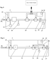
- Figure 1 describes schematically an overview of one variation of a device for capturing exhaled breath, including a sampling cannula 1 and a gas sample collection and analysis instrument 2.
- Gas may be drawn from the patient, for example using a sampling cannula 1 and a flow generator 12.
- the flow rate of the flow generator may be measured by a flow transducer, for example a pressure sensor array, 26 and 28, arranged like a pneumotach.
- the measured flow rate may be used as a closed loop feedback control to control the flow generator flow rate.
- a breath sensor such as a Capnometer 10 or a pressure sensor 26, is used to measure the breathing pattern in real time. Gas from the desired portion of the breath is captured and isolated in the storage collection compartment 18.
- Gas entering the storage compartment is controlled by at least one valve V1, for example with a common port c always open, and a second open port, either a to collect gas or b to isolate the storage compartment.
- Gas not being captured for analysis is channeled away from the storage compartment via a bypass conduit 20.
- the captured gas is sent from the storage compartment through a gas composition analyzer 14, such as a NO sensor.
- a control system 22 with a microprocessor 24 controls the system with the associated algorithms.
- the flow generator for example can be a vacuum or pressure pump, such as a diaphragm pump, or another type of flow generating device such as a vacuum source, a Venturi from a positive pressure source, or a syringe pump.
- Valves to manage gas routing can be an arrangement of 3 way 2 position valves as shown, or can be an arrangement of 4-way 3-position valves.
- Capnometer 10 if used, measures the breathing pattern instantaneously using infrared (IR).
- the gas composition analyzer for example can be an electrochemical sensor with a reaction time, or a gas chromatographer, a mass spectrometer, a chemiluminescence sensor, an amperometric sensor, or any type of chemical sensor in which the chemistry has been tuned to react to presence of NO.
- the sensor may measure NO directly, or convert the NO to another molecule such as NO 2 and measure it.
- the sample storage compartment can be a small bore inner diameter tube or conduit of considerable length in order to minimize the cross section which reduces gas molecule interaction along the length of the conduit.
- the sampling cannula may be constructed of non-rigid kink-resistant plastic, such as a thermoset plastic for example silicone, urethane or urethane blends, or such as a thermoplastic for example PVC, C-FLEX, or other materials.
- the cannula can have a range of inner diameters, but preferably less than 080" in order for the breath gas to conform to columnar behavior with a discrete well-defined boundary between breath sections where mixing across may be controlled.
- Pressure sensor 16 is an additional pressure sensor that may be used in tandem with 26 so that a flow rate can be determined, in addition to using it for airway pressure measurement. Flow rate can be used to adjust the pump speed in some variations that utilize a variable flow rate. Pressure sensor 16 can also be utilized for ambient information where the breathing curve is measured by pressure instead of Capnometer. In some variations, an instantaneous nitric oxide sensor may be used as the breath sensor, in place of a capnometer or an airway pressure sensor. Other instantaneous breath sensors may also be used.
- the bypass tube 20 allows the gas being drawn from the patient or from ambient to bypass the sample tube 18 during times which the sample tube may be isolated from these gases.
- valve V1 may be closed at port a and valve V2 may be open at port b to allow flow from b through c.
- a flow generator may be used to draw the sampling gas through the bypass type.
- a push tube 21 may be used to push the end-tidal sample in the sample tube 18 out of the sample tube to the sensor 14, at which time valves V1 and V3 are each open at port b and V2 is closed at port a.
- Valve V4 switches the source gas from patient gas to ambient gas by opening port b, when it is desired to not contaminate the internal gas pathways with patient gas or for purging the system.
- the pneumatic system shown in Figure 1 above may include a removable sampling compartment (for example, as described in Capnia's provisional patent application 61/872,514 , the content of which are incorporated by reference herein in its entirety).
- sample tube 18 may be removable form the system.
- the pneumatic system may be able to fill a sample tube with a desired gas, and the sample tube may be analyzed at another location, or preserved for later analysis.
- the gas may be routed from the sample tube to a removable sampling compartment.
- the compartment may replace the analyzer or otherwise be positioned so that it can be removed and/or replaced.
- the control system 22 may include a module or algorithm for performing the breath monitoring and detection function.
- a determination is made if the breathing pattern or individual breaths meet certain criteria, in order to determine whether or not a breath will be captured for analysis.
- the criteria may be predefined, or defined in real-time, or user-defined, automatically defined or semi-automatically defined.
- predefined criteria may be absolute or relative threshold parameters stored in the device's software.
- a user may enter certain information relative to the specific test being performed, and the system may use that information to define the criteria.
- the system can automatically establish the criteria in real time based on the prevailing conditions. Or a combination of the above techniques can be employed.
- a subsequent control system module or algorithm within the control system performs the breath sample capturing function, and another subsequent control system module or algorithm performs the breath sample analysis.
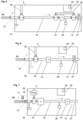
- Figure 2 describes an alternative instrument configuration in which exhaled gas is drawn into the instrument by a pump 12 through valves V5 and V6 until a breath is selected for analysis and until the beginning of an appropriate portion of exhaled gas from that selected breath reaches the tee T1.
- valve V6 switches from port a to port b and the flow of gas consisting of the appropriate portion of exhaled gas is then routed to sensor S6.
- sensor S6 completes its measurement of the concentration of the analyte in the gas sample.
- valves b of V3 and V4 are open when not measuring the designated sample and ports a are open when measuring the designated sample.
- Figure 3 describes an alternative instrument configuration in which the gas compositional analysis is performed off-board.
- V7 When the desired section of gas from the desired breath reaches valve V7, V7 and V6 are switched from ports a to ports b, allowing the sample designated for analysis to travel to sample conduit 29.
- Conduit 29 may be removable so that it can be coupled to the remote analyzer S3, or the instrument 2 may simply connect to the independent analyzer S3.
- V7 When the designated sample has cleared valve V7, V7 and V6 switch back to ports a so that the measurement of the designated sample is not contaminated with other gases.
- Figure 5 describes an alternative instrument configuration similar to Figure 4 in which there is an additional channel 15 in the patient interface 1, in this case a nasal cannula interface.
- the sensor S1 is coupled to channel 15 to measure the breathing signal.
- S1 may be a pressure sensor, flow sensor or other type of sensor.
- Channel 15 is shown to be not coupled to an active flow source in which case the breathing signal is passively generated by the patient's breathing, however also contemplated the channel 15 may be coupled to a vacuum source to actively draw the gas from the sensor, in which case S1 may be a Capnometer or gas composition sensor.
- the vacuum source may be the same as pump 12 shown, or another component (not shown) independent of pump 12.
- Figure 6 describes an alternative instrument configuration in which a sensor S2 may be used to measure the breathing signal and also used to measure the concentration of the analyte in question.
- the sensor S2 is a relatively fast responding sensor, such as within 100 msec response time when responding to the analyte in question.
- This system may still include pressure sensors 16 and 28 to help regulate sampling flow rate, and or as a redundancy to the breathing signal measurement.
- Figure 7 shows an alternative instrument configuration in which the collection of exhaled gas is passive, not requiring an active flow source for the collection of the sample.
- a valve configuration is placed near the patient interface connection to the instrument.
- the configuration includes an inspiratory valve 17 and an expiratory valve 19.
- the patient breathes spontaneously through the patient interface, drawing ambient inspired air through valve 17, and exhaling into the instrument through valve 19.
- the exhaled gas breathing signal is measured by sensor S1 which will identify the different portions of the expiratory phase.
- sensor S2 When gas from the desired portion of exhalation passes through sensor S2 it is measured for its concentration of the analyte.
- a pump 25 is provided to purge the system with ambient air, or to measure the gas in question in the ambient air for correction.
- the configuration in Figure 7 can be combined with other alternative instrument configurations for example Figure 5 in which there is a bypass 20 around the sensor S2 for all other gases other than the designated sample.
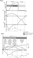
- typical breathing signals are shown graphically as a function of time for an expiratory phase of one breath and the inspiratory phase of the subsequent breath.
- the top, middle and lower tracing correspond to a Capnometer signal, airway pressure signal and flow signal respectively, for a normal tidal volume breath.
- the CO 2 signal can be from a side-stream sensor such as S1 in Figure 5 , or a mainstream CO 2 sensor, and the airway and flow sensors can be at the patient airway or a distance away from the airway.
- CO 2 can be from a side-stream sensor such as S1 in Figure 5 , or a mainstream CO 2 sensor, and the airway and flow sensors can be at the patient airway or a distance away from the airway.
- CO 2 During the expiratory phase E, CO 2 is expelled, hence the CO 2 level increases.
- ambient air occupies the upper airways, hence the measured CO 2 drops to essentially zero.
- a classic curve may show the following sub-portions for the expiratory phase: (1) a beginning portion or pre-end-tidal section PET, comprising low or little CO 2 because the gas may simply be gas from the proximal airway devoid of CO 2 , (2) a middle portion showing CO 2 rapidly increasing from zero to the CO 2 level at the distal segments of the lungs, and (3) an end-tidal ET portion showing a plateauing or leveling off of the CO 2 , representing the CO 2 coming from the alveoli for that exhaled breath, and (4) potentially a constant peak level at the very end of the expiratory period.
- Peak CO 2 levels are typically 4-6% during the end-tidal period and close to or equal to zero during the inspiratory period.
- the level of CO 2 in an exhaled breath may be used to determine the duration of a period of a breath, such as the pre-end-tidal time TPET, expiratory time TE, end-tidal time TET, inspiratory time TI, or breath period time TBP.
- a duration of a period of breath may be characterized by a start and a termination of that period.
- a CO 2 level may be used to determine a start or a termination of a period of a breath.
- a first time derivative of a CO 2 level may be used to determine a start or a termination of a period of a breath.
- a second time derivative of a CO 2 level may be used to determine a start or a termination of a period of a breath.
- a combination of CO 2 levels and CO 2 level time derivatives may be used to determine a start or a termination of a period of a breath.
- a start of an end-tidal period may be determined by a change in the first time derivative of a CO 2 level of the exhaled breath, such as a sudden decrease in the first time derivative of the CO 2 level.
- a decrease in the first time derivate of the CO 2 level may be more than a 10% decrease.
- a decrease in the first time derivate of the CO 2 level may be more than a 25% decrease.
- the derivative will approach or become zero showing very little rate of change or a peak plateau respectively.
- the start of an end-tidal period may be determined by a large second time derivative of the CO 2 level.
- a termination of an end-tidal period may be determined by a maximum CO 2 level, which may be detected or confirmed by a change in the sign of the first time derivative of the CO 2 level as the derivative becomes negative associated with a drop of the CO 2 level from its peak value.
- a start of a beginning period may be determined by a sudden increase in the first time derivative of the CO 2 level.
- the start of a beginning period may be determined by an increase in the CO 2 level from zero CO 2 level.
- a termination of a middle period may be determined by a change in the first time derivative of a CO 2 level of the exhaled breath, such as a sudden decrease in the first time derivative of the CO 2 level.
- a CO 2 level, first time derivative thereof, or second time derivative thereof may be used to determine the start and termination of one or more periods.
- Other breath-borne gases may be used in place of CO 2 for measuring the breathing curve. For example, oxygen can be measured which would indicate a higher oxygen concentration during inspiration than expiration.
- the breathing pattern may be instantaneously or substantially instantaneously measured by a fast-responding NO sensor.
- the senor 10 may be a fast responding NO sensor that depicts the breathing pattern and also measures the end-tidal NO level. After application of the various breath qualification and disqualification variations described subsequently, the NO level of a qualified breath can be reported as the result.
- the measured airway pressure signal may be from sensor 10 in Figure 5 , showing a negative pressure during inspiratory phase and a positive pressure during expiratory phase.
- the peak expiratory pressure may correspond to the middle of the expiratory phase and the start of the end-tidal period.
- TI, TE, TPET, TET, TPE represent inspiratory time, expiratory time, pre-end-tidal time, end-tidal time, and post expiratory time respectively.
- An inspiratory pause may also be present (not shown), in which the peak of lung muscle movement during inspiration is paused before the expiratory period begins.
- Peak inspiratory pressure may be - 1 to -4 cwp during restful breathing, and up to -15 cwp during heavier breathing, and peak expiratory pressure may be +0.5 to +2.0 cwp during restful breathing and up to +10 cwp during heavier breathing when measured at the entrance to the nostrils.
- Representative pressures and gas concentrations may vary with environmental conditions, for example airway pressures during cold temperatures may be increased for the same unit of volume. In the lower tracing of Figure 8 a breathing flow rate is measured for example from Sensor S1 in Figure 5 .
- airway pressure may be used to determine a start or a termination of a period of a breath.
- a first time derivative of an airway pressure may be used to determine a start or a termination of a period of a breath.
- a second time derivative of an airway pressure may be used to determine a start or a termination of a period of a breath.
- a combination of airway pressures and airway pressure time derivatives may be used to determine a start or a termination of a period of a breath.
- a start of an end-tidal period may be determined by maximum airway pressure, that is, by a zero first time derivative of the airway pressure.
- a termination of an end-tidal period may be determined by zero airway pressure.
- an airway pressure, first time derivative thereof, or second time derivative thereof may be used to determine the start and termination of one or more periods.
- Airway pressure may be measured through a secondary lumen extending the length of the cannula in parallel with the sampling lumen, or may be measured by teeing into the sampling lumen, or by placing a sensing transducer at the airway of the patient.
- the breath sensor monitors the person's breathing over time, and trends the breathing pattern by determining a continually updated value that is characteristic of the breathing pattern. For example, peak positive values of a breathing signal may be measured and updated for each breath. Peak values may be compared with previous peak values. Peak values may be averaged over a previous number of multiple breaths. Similarly, time-related aspects of the breaths may be trended, such as the expiratory time. Various breath-related events that are not normal breaths may be identified and exception algorithms may exist in order to not include these non-normal breath events inadvertently in deterministic steps. For example, the characteristic waveform of a sneeze, cough, stacked breath, or non-full breath may be defined in advance or based on monitoring of a particular patient, and when detected by the breathing sensor, discarded by the appropriate deterministic algorithms.
- FIG. 9 the expiratory phase of breathing is graphically partitioned into physiologically different partitions, corresponding to different anatomical regions of the pulmonary tree of the lung.
- a Capnometer tracing 50, airway pressure tracing 51 and flow rate tracing 53 are shown, as well as a theoretical NO concentration tracing 55 of a patient with an exacerbation of airway inflammation indicative of an ensuing asthma attack.
- the scale of the NO tracing can typically be from 0 to 300 ppb, although higher levels may be measured as well.
- 5 partitions are created for a single expiration, in this case a normal tidal volume breath such as that shown in Figure 8 .
- the first partition is the section of exhalation corresponding to oro-nasal volume, tracheal volume, and lobar bronchi volume.
- the second partition is the section of exhalation corresponding to lung airways in the middle of the lung's lower lobes and lower part of the lung's upper lobes. For example, these are the airways between the segmental bronchi to the 6 th branching generation of the pulmonary tree, inclusive. These airways in particular may be prone to the inflammation that occurs in asthma.
- These airways may also be referred to the conducting airways, being the conduits responsible for conducting the respiratory gases to and from the gas exchange areas in the distal most regions of the lung, known as the alveoli.
- the third of five partitions is the section of exhaled gas corresponding to the lower airways of the lower lobes of the lung and some alveolar gas from the upper lobes.
- the fourth and fifth partitions contain increasing percentages of alveolar gas until the gas is 100% pure alveolar gas.
- the partitioning of the expiratory gas into different sections of the bronchopulmonary tree includes some heterogeneous zones where alveolar gas and conducting airway gas is being expelled out of the nose or mouth at the same time. Therefore, this heterogeneity may be taken into account when partitioning the expiratory phase into different anatomical or physiological sections.
- the third partition contains both airway gas and some alveolar gas hence it may be beneficial to limit analyzing the gas from this section.
- the gas from the second partition based on this graphical example, appears to be a good section from which to collect NO gas for analysis.
- the inflammatory process involves the lower airways of the lung, and these variations may be used to identify, partition and analyze gas from those lower airways even if that gas, when exiting the patient's nose or mouth, may contain some alveolar gas from the upper lobes.
- the sensor used to measure the breathing signal is used to assign timestamp values to the start and end of each partition of the expiratory phase.
- the timestamp values will allow the system to know the location of each partition inside the instrument at any given time as explained elsewhere.
- the expiratory duration is determined and after the expiratory phase is complete, this duration is divided into the required number of sections.
- section 1 will be identified and located as timestamp values t(i) through [ t(i) + t(exp)/5]
- section 2 will be [t(i) + t(exp)/5] through [t(i) + t(exp) ⁇ 4/5], and so on.
- the beginning and end of each expiratory partition is determined in real time as the expiratory gas travels through or to the sensor S1 or 16.
- the timestamps of the different partitions are determined by characteristics in the breath sensor signal or the processed signal, such as a sudden increase or decrease, a crossing of zero, a slope requirement, or other characteristics.
- One or more sensors can be used to obtain enough information to make the timestamp assignments, and the signals can be amplified, differentiated, transformed or converted in other ways as explained elsewhere.
- a pressure sensor can be used to determine the start and end of the expiratory phase, by a positive slope crossing zero and a negative slope crossing zero respectively. Or the drop in a CO 2 signal can demark the end of an expiratory cycle. Inflection points of the airway pressure or CO 2 signals may mark intermediate points along the expiratory phase.
- the beginning and end of the second partition is given time stamp values of t1 and t2 respectively. For example t(1) may be determined by an increase in the CO 2 signal, and t(2) can be determined by a peak in the airway pressure signal.
- the two approaches can be combined. These time stamps will allow the instrument to know the location of the gas from that section of breath while inside the instrument at any given time.
- FIG 10 an example of an overall test sequence is graphically described as a function of time.
- the patient interface such as a nasal cannula is fastened to the patient and coupled to the airway.
- a breathing sensor monitors the breathing pattern to verify stable breathing.
- the breathing pattern is shown by the tracing and can be for example Capnometer, airway pressure, flow or other breathing parameters.
- the instrument verifies that the breathing is stable according to a set of criteria. The criteria will insure steady state gas diffusion conditions in the lung exist so that a physiologically accurate NO sample can be obtained. After the appropriate acclimation period criteria are met, the instrument begins to look for a valid breath for sampling for the NO measurement.
- breath characteristics may be required to meet a set of criteria to ensure that the sample is taken from a physiologically representative breath. Breaths classified as not valid will be rejected for analysis.
- breath bn is determined as valid and is targeted for sample acquisition.
- the instrument's partitioning algorithms then isolate the desired section of exhaled gas from breath bn for compositional analysis, for example the middle airway gas for NO analysis.
- Figure 11 shows the exhalation phase of breath bn in Figure 10 in more detail, showing the Capnometer, airway pressure, flow and theoretical NO levels 50, 51, 53 and 55 respectively versus time.
- Figure 12a the graph shown in Figure 11 is shown with the timescale flipped, such that the most recent time point of the expiratory tracing of breath bn is on the left hand side of the graph.
- Figure 12b is a pneumatic schematic of the instrument shown in Figure 5 , in which the sample tube 18 is schematically aligned with the graph shown in Figure 12a .
- the second fifth of the expiratory cycle is the portion of the expiratory cycle that is targeted in breath bn for NO measurement, to represent the NO level in the middle airways.
- the sample of gas between time points t1 and t2 is drawn into the sample tube 18 between sensor S1 and valve V3.
- the gas flow path is path b around the sensor S2 and out the pump, however, once gas from time point t1 reaches valve V3, the control system changes the valve positions to ports a and the gas flow path is then path a so that the middle airway gas sample from the second exhalation zone travels through sensor S2 for compositional analysis.
- the control systems changes the valve positions again to port b so that the remaining gas bypasses the sensor S2 by flowing through path b, so that this gas does not interfere with the middle airway NO measurement.
- the control system is able to switch the valve porting at the correct times.
- the timestamps t(1) and t(2) are determined in real time or near real time as the gas travels through the sensor S1 and before the gas reaches valve V3.
- the gas travels in path b around the sensor S2 and when the second section reaches valve V3 the valves are switched to port a and the gas travels through the sensor S2 in path a.
- valve V3 When the end of the second section of gas clears valve V3, the valves are switched back to port b and the subsequent gas travels around the sensor S2 to limit contaminating the measurement of the second section of gas.
- the distance between valve V3 and sensor S2 may be taken into account in the valve control timing so that only the desired gas reaches and is measured by sensor S2.
- the timestamp values can be determined and assigned in real time as the expiratory gas is traveling through sensor S1, or can be done after all the exhaled gas has traveled through the sensor S1 so that the system has a chance to measure the complete expiratory cycle, or a combination of the above.
- Figure 13a and 13b an example of analyzing the second expiratory partition from breath bn from Figure 10 is shown, and in which the entire expiratory cycle of breath bn is drawn past the sensor S1 into the sample tube 18 prior to reaching the valve V3.
- the timestamp values required to identify the start and stop of the second expiratory partition are determined for this section of gas before it reaches valve V3, using the breathing sensor signal and techniques described elsewhere.
- valve V3 Before the second section reaches valve V3 the gas travels in path b around the sensor S2 and when the second section reaches valve V3 the valves are switched to port a and the gas travels through the sensor S2 in path a. When the end of the second section of gas clears valve V3, the valves are switched back to port b and the subsequent gas travels around the sensor S2 to limit contaminating the measurement of the second section of gas.
- the distance between valve V3 and sensor S2 may be taken into account in the valve control timing so that only the desired gas reaches and is measured by sensor S2.
- Figure 14 describes another variation in which gas samples are taken from more than one type of breathing pattern, and analyzed and compared. The comparison may increase the sensitivity and specificity of the test for a specific diagnosis.
- samples can be collected for more than two types of breathing patterns, for example fast, slow and normal. Typically there are acclimation periods before collecting the samples so that steady state conditions are obtained and typically the instrument instructs the patient on how to breathe and verifies the patient is breathing as required to validate a test sequence.
- inflammation of the segmental bronchi may correlate to a certain type of asthma, or a certain type of irritant causing an attack.
- inflammation of the lower airways such as the 6 th - 8 th generation of the airway branching structure, may correlate to a different type of asthma or a different irritant. Therefore, some variations may be useful in finding which portion of the bronchopulmonary tree is most affected by the inflammation. This information can help the clinician determine the optimal treatment and even a cure.
- Figure 15 graphically describes a hypothetical gradient of NO gas in the expiratory phase.
- the expiratory phase is divided into 10 sections s1 through s10 in order to partition the expiratory phase into enough sections to determine an airway NO gradient.
- section s4 there is a peak in airway NO (aNO) of 50ppb, indicating the most inflammation is found to be associated with this section which may represent for example the subsegmental airways, and which is indicative of a certain hypothetical genotype of asthma or a form of asthma prone to a certain irritant.
- the instrument shown in Figure 5 is adapted to take aNO measurements from all the sections s1 through s10 either from one breath or from multiple breaths including each section from one dedicated breath.
- the contribution of nasal NO to conducting airways NO may be taken into account.
- the nasal NO may be measured at 100ppb in a first test measuring the nasal NO using the techniques described herein. Then, in a second test of a similar breath, or in the same test as the nasal NO test, the NO in the conducting airways may be measured at 10ppb, however, it may contain some nasal NO.
- ambient NO may be measured during gas collected via the cannula during the inspiratory phase of breathing, and the conducting airways NO measurement may be corrected for the ambient NO measurement.
- the techniques described herein may provide different measured aNO values compared to the current clinical practice FENO values, even within intra-patient values. Therefore, a correlation of aNO values obtained with this techniqueto FENO values obtained with conventional FENO values is first established. This can be done by performing adult measurements, pediatric measurements, as well as measurements on younger pediatric and infant patients who cannot follow the breathing instructions of the conventional techniques. For the latter, the measurements can be collected by trial and error over the course of a number of attempted measurements for a given test subject, and a valid measurement obtained. After the correlation of aNO to FENO is established, the apparatuses described herein may be able to report to the user both the measured aNO value just measured, and, based on the previously established correlations, report the estimated FENO value for comparison.
- Figures 16-19 describe different patient interfaces that may be used to collect the exhaled gas sample from the patient including a nasal cannula, nasal mask, oral mask, and facemask.
Claims (15)
- Appareil pour analyser des niveaux d'oxyde nitrique dans la respiration, comprenant :une canule d'échantillonnage nasal (1) ;un capteur de respiration pour mesurer un paramètre de schéma respiratoire ;un système d'échantillonnage de gaz respiratoire comprenant une pluralité de vannes (V1-V7) pour isoler des sections du système d'échantillonnage de gaz respiratoire ;une pompe (12) en aval d'au moins deux de la pluralité de vannes (V1-V7) qui aspire une pluralité de respirations d'un patient dans la canule d'échantillonnage nasale (1) et à travers le système d'échantillonnage de respiration ;un premier processeur contenant des instructions exécutables pour analyser les paramètres du schéma respiratoire de la pluralité de respirations ;un deuxième processeur contenant des instructions exécutables pour établir en temps réel, sur la base des paramètres de schéma respiratoire analysés de la pluralité de respirations, des critères de paramètre de schéma respiratoire qui délimitent une respiration physiologiquement représentative et une respiration physiologiquement non représentative ;un troisième processeur contenant des instructions exécutables pour déterminer si un paramètre de schéma respiratoire d'une respiration, expirée après la pluralité de respirations, répond aux critères de paramètre de schéma respiratoire ;un quatrième processeur contenant des instructions exécutables pour, en réponse à une détermination qu'un paramètre de schéma respiratoire de la respiration satisfait les critères de paramètre de schéma respiratoire, délimiter au moins une première section de la respiration, une deuxième section de la respiration, et une troisième section de respiration, la première section de respiration étant expirée avant la deuxième section de respiration et la deuxième section de respiration étant expirée avant la troisième section de la respiration ;un cinquième processeur contenant des instructions exécutables pour commander la pluralité de vannes (V1-V7) afin d'isoler la première section de respiration, la deuxième section de respiration et la troisième section de respiration les unes des autres ; etun analyseur (14) pour analyser les niveaux d'oxyde nitrique dans au moins une de la deuxième section de la respiration et de la troisième section de la respiration séparément de l'autre.
- Appareil selon la revendication 1, les instructions exécutables pour commander la pluralité de vannes comprenant des instructions exécutables pour rejeter la première section de respiration.
- Appareil selon la revendication 1, les premier, deuxième, troisième, quatrième et cinquième processeurs comprenant un seul processeur.
- Appareil selon la revendication 1, les critères de paramètre de schéma respiratoire comprenant une mesure d'un paramètre de stabilité de la fréquence respiratoire en fonction du temps et une mesure d'un paramètre de fréquence respiratoire.
- Appareil selon la revendication 1, la deuxième section de respiration correspondant à une section de l'arbre broncho-pulmonaire entre une section proximale et une section distale, ou la deuxième section de respiration correspondant à une section de l'arbre des voies respiratoires choisie dans le groupe constitué par : les voies aériennes nasales, la trachée, les bronches de souche principale, les bronches segmentaires, les voies aériennes conductrices, les voies aériennes respiratoires et les alvéoles.
- Appareil selon la revendication 5, la section proximale étant une bronche de souche principale et la section distale étant une structure sélectionnée dans le groupe consistant en une 4ème ou 8ème structure de ramification.
- Appareil selon la revendication 1, les instructions exécutables pour délimiter au moins une première section de la respiration, une deuxième section de la respiration et une troisième section de la respiration comprenant des instructions exécutables pour délimiter une quatrième section de la respiration et une cinquième section de la respiration, ou comprenant des instructions exécutables pour déterminer une durée d'au moins une partie d'une phase d'expiration et diviser la durée en sections temporelles correspondant à la première section de la respiration, à la deuxième section de la respiration et à la troisième section de la respiration, ou comprenant des instructions exécutables pour déterminer des caractéristiques dans le signal du capteur de respiration, les caractéristiques étant sélectionnées dans le groupe constitué de : une amplitude de signal nulle, une amplitude de signal de pointe, un passage par zéro d'une valeur négative à une valeur positive, un passage par zéro d'une valeur positive à une valeur négative, un plateau dans l'amplitude du signal, un changement de pente de l'amplitude du signal, un zéro du différentiel du signal, une pointe du différentiel du signal, un zéro du second différentiel du signal, une pointe du second différentiel du signal, un zéro d'une transformée du signal, une pointe d'une transformée du signal.
- Appareil selon la revendication 1, comprenant en outre :a) un sixième processeur comprenant des instructions exécutables pour notifier à un patient de respirer à une fréquence souhaitée ; et un septième processeur comprenant des instructions exécutables pour vérifier que le patient respire à la fréquence souhaitée, les instructions exécutables pour déterminer si un paramètre de schéma respiratoire de la respiration satisfait aux critères de paramètre de schéma respiratoire comprenant des instructions exécutables pour collecter la respiration après une vérification que le patient respire à une fréquence souhaitée ;b) un huitième processeur comprenant des instructions exécutables pour mesurer l'oxyde nitrique dans au moins deux sections de la respiration et corriger le niveau d'oxyde nitrique mesuré dans une section physiologiquement valide avec l'oxyde nitrique mesuré dans une autre section ; ouc) un neuvième processeur comprenant des instructions exécutables pour mesurer l'analyte dans plusieurs respirations afin de déterminer une valeur de composition finale.
- Procédé d'analyse des niveaux d'oxyde nitrique dans la respiration, comprenant :l'aspiration d'une pluralité de respirations d'un patient respirant normalement en utilisant une canule d'échantillonnage nasale (1), une pompe (12) étant utilisée pour aspirer la pluralité de respirations ;l'analyse de paramètres du schéma respiratoire de la pluralité de respirations ;l'établissement en temps réel, sur la base des paramètres de schéma respiratoire analysés de la pluralité de respirations, de critères de paramètre de schéma respiratoire qui délimitent une respiration physiologiquement représentative et une respiration physiologiquement non représentative ;la détermination si un paramètre de schéma respiratoire d'une respiration, expirée après la pluralité de respirations, satisfait aux critères de paramètre de schéma respiratoire ;en réponse à une détermination qu'un paramètre de schéma respiratoire de la respiration satisfait aux critères de paramètre de schéma respiratoire, la délimitation d'au moins une première section de la respiration, d'une deuxième section de la respiration, et d'une troisième section de la respiration, la première section de respiration étant expirée avant la deuxième section de respiration et la deuxième section de respiration étant expirée avant la troisième section de respiration ;la commande d'une pluralité de vannes (V1-V7) pour isoler la première section de respiration, la deuxième section de respiration et la troisième section de respiration les unes des autres ; etl'analyse de niveaux d'oxyde nitrique dans au moins une de la deuxième section de la respiration et de la troisième section de la respiration séparément de l'autre.
- Procédé selon la revendication 9, la commande de la pluralité de valves comprenant le rejet de la première section de respiration.
- Procédé selon la revendication 9, les critères de paramètre de schéma respiratoire comprenant une mesure d'un paramètre de stabilité de la fréquence respiratoire en fonction du temps et une mesure d'un paramètre de fréquence respiratoire.
- Procédé selon la revendication 9, la deuxième section de respiration correspondant à une section de l'arbre broncho-pulmonaire entre une section proximale et une section distale, ou la deuxième section de respiration correspondant à une section de l'arbre des voies respiratoires choisie dans le groupe constitué par : les voies aériennes nasales, la trachée, les bronches de souche principale, les bronches segmentaires, les voies aériennes conductrices, les voies aériennes respiratoires et les alvéoles.
- Procédé selon la revendication 12, la section proximale étant une bronche de souche principale et la section distale étant une structure choisie dans le groupe constitué par une 4ème à une 8ème structure de ramification.
- Procédé selon la revendication 9, la délimitation d'au moins une première section de la respiration, d'une deuxième section de la respiration et d'une troisième section de la respiration comprenant :la délimitation d'une quatrième section de la respiration et d'une cinquième section de la respiration, oula détermination d'une durée d'au moins une partie d'une phase d'expiration et la division de la durée en sections temporelles correspondant à la première section de la respiration, à la deuxième section de la respiration et à la troisième section de la respiration, oula détermination de caractéristiques dans le signal du capteur de respiration, les caractéristiques étant choisies dans le groupe constitué par : une amplitude de signal nulle, une amplitude de signal de pointe, un passage par zéro d'une valeur négative à une valeur positive, un passage par zéro d'une valeur positive à une valeur négative, un plateau dans l'amplitude du signal, un changement de pente de l'amplitude du signal, un zéro du différentiel du signal, une pointe du différentiel du signal, un zéro du second différentiel du signal, une pointe du second différentiel du signal, un zéro d'une transformée du signal, une pointe d'une transformée du signal.
- Procédé selon la revendication 11, comprenant en outre :a) la notification à un patient de respirer à une fréquence souhaitée ; et
la vérification que le patient respire à la fréquence souhaitée, la détermination si un paramètre de schéma respiratoire de la respiration satisfait les critères de paramètre de schéma respiratoire comprenant la collecte de la respiration après une vérification que le patient respire à une fréquence souhaitée ; oub) la mesure de l'oxyde nitrique dans au moins deux sections de la respiration ; et
la correction du niveau d'oxyde nitrique mesuré dans une section physiologiquement valide avec l'oxyde nitrique mesuré dans une autre section ; ouc) la mesure de l'analyte dans plusieurs respirations pour déterminer une valeur de composition finale.
Applications Claiming Priority (2)
| Application Number | Priority Date | Filing Date | Title |
|---|---|---|---|
| US201461968290P | 2014-03-20 | 2014-03-20 | |
| PCT/US2015/021852 WO2015143384A1 (fr) | 2014-03-20 | 2015-03-20 | Sélection, segmentation et analyse de l'air expiré pour l'évaluation de troubles des voies respiratoires |
Publications (3)
| Publication Number | Publication Date |
|---|---|
| EP3119278A1 EP3119278A1 (fr) | 2017-01-25 |
| EP3119278A4 EP3119278A4 (fr) | 2017-11-15 |
| EP3119278B1 true EP3119278B1 (fr) | 2022-02-23 |
Family
ID=54140918
Family Applications (1)
| Application Number | Title | Priority Date | Filing Date |
|---|---|---|---|
| EP15764503.7A Active EP3119278B1 (fr) | 2014-03-20 | 2015-03-20 | Sélection, segmentation et analyse de l'air expiré pour l'évaluation de troubles des voies respiratoires |
Country Status (7)
| Country | Link |
|---|---|
| US (2) | US20150265184A1 (fr) |
| EP (1) | EP3119278B1 (fr) |
| JP (2) | JP6788503B2 (fr) |
| CN (1) | CN106456053A (fr) |
| AU (2) | AU2015231003B2 (fr) |
| CA (1) | CA2943243A1 (fr) |
| WO (1) | WO2015143384A1 (fr) |
Families Citing this family (37)
| Publication number | Priority date | Publication date | Assignee | Title |
|---|---|---|---|---|
| AU2003238288A1 (en) | 2003-06-19 | 2005-02-04 | Everest Biomedical Instruments | Breath end-tidal gas monitor |
| CN108125683B (zh) | 2011-12-21 | 2021-12-14 | 卡普尼亚公司 | 在补偿呼吸参数频率的情况下收集并分析一定体积的呼出的气体 |
| JP6424172B2 (ja) | 2013-01-08 | 2018-11-14 | キャプニア, インク.Capnia, Inc. | 分析のための呼吸選択 |
| EP2956058A4 (fr) | 2013-02-12 | 2016-11-02 | Capnia Inc | Dispositif d'enregistrement d'échantillonnage et de stockage pour l'analyse d'un gaz respiratoire |
| WO2015031850A1 (fr) | 2013-08-30 | 2015-03-05 | Capnia, Inc. | Système de mesure de dioxyde de carbone néonatal |
| EP3096821B1 (fr) * | 2014-01-24 | 2019-11-13 | Circassia Ab | Dispositif miniaturisé de régulation d'écoulement de fluide |
| US10806372B2 (en) * | 2014-09-09 | 2020-10-20 | Siemens Healthcare Gmbh | Method and system for simultaneous evaluation of airway wall density and airway wall inflammation |
| US11262354B2 (en) | 2014-10-20 | 2022-03-01 | Boston Scientific Scimed, Inc. | Disposable sensor elements, systems, and related methods |
| US10226201B2 (en) | 2015-10-29 | 2019-03-12 | Invoy Holdings, Llc | Flow regulation device for breath analysis and related method |
| EP3448254A1 (fr) * | 2016-04-25 | 2019-03-06 | Owlstone Medical Limited | Procédé de collecte d'une partie sélective de l'haleine d'un sujet |
| EP3448256B1 (fr) * | 2016-04-25 | 2023-09-20 | Owlstone Medical Limited | Systèmes et dispositif de capture d'échantillons d'haleine |
| US9933445B1 (en) | 2016-05-16 | 2018-04-03 | Hound Labs, Inc. | System and method for target substance identification |
| WO2017218464A1 (fr) | 2016-06-15 | 2017-12-21 | Boston Scientific Scimed, Inc. | Cathéters d'échantillonnage de gaz |
| PT109617A (pt) | 2016-09-12 | 2018-03-12 | Faculdade De Ciencias E Tecnologia Da Univ Nova De Lisboa | Sistema para recolha controlada e seletiva de ar exalado e respetivo método de operação |
| EP3528703A1 (fr) * | 2016-10-21 | 2019-08-28 | Boston Scientific Scimed, Inc. | Dispositif d'échantillonnage de gaz |
| CN110769742B (zh) | 2017-05-19 | 2022-07-29 | 波士顿科学国际有限公司 | 用于评定患者的健康状况的系统和方法 |
| US20200229735A1 (en) * | 2017-07-17 | 2020-07-23 | University Of Southern California | Measuring exhaled nitric oxide with variable flow rate |
| US10852264B2 (en) | 2017-07-18 | 2020-12-01 | Boston Scientific Scimed, Inc. | Systems and methods for analyte sensing in physiological gas samples |
| US11187711B1 (en) | 2017-09-11 | 2021-11-30 | Hound Labs, Inc. | Analyte detection from breath samples |
| US11209417B2 (en) | 2017-10-12 | 2021-12-28 | Carrot, Inc. | Breath sensor apparatus and methods of use |
| CN109009023A (zh) * | 2018-08-03 | 2018-12-18 | 深圳市大耳马科技有限公司 | 一种呼吸信号的提取方法、装置、处理设备和系统 |
| CA3108093A1 (fr) * | 2018-08-07 | 2020-02-13 | Rostrum Medical Innovations Inc. | Systeme et procede de surveillance d'un debit sanguin n'interagissant pas avec les poumons ventiles d'un patient |
| US11426097B1 (en) * | 2018-10-17 | 2022-08-30 | Hound Labs, Inc. | Rotary valve assemblies and methods of use for breath sample cartridge systems |
| CN112930480A (zh) | 2018-10-19 | 2021-06-08 | 明尼苏达大学董事会 | 用于检测脑病症的系统和方法 |
| EP3861329A1 (fr) | 2018-11-27 | 2021-08-11 | Boston Scientific Scimed Inc. | Systèmes et méthodes de détection d'un état de santé |
| CN113196047A (zh) | 2018-12-18 | 2021-07-30 | 波士顿科学国际有限公司 | 用于测量化学传感器元件的动力学响应的系统和方法 |
| JP7189011B2 (ja) * | 2018-12-26 | 2022-12-13 | 日本特殊陶業株式会社 | 呼気ガス検知装置 |
| US20200245899A1 (en) | 2019-01-31 | 2020-08-06 | Hound Labs, Inc. | Mechanical Breath Collection Device |
| US11596326B2 (en) * | 2019-12-06 | 2023-03-07 | Koninklijke Philips N.V. | Systems and methods for metabolic monitoring |
| US20230012942A1 (en) * | 2019-12-10 | 2023-01-19 | Kyocera Corporation | Health condition estimation apparatus and health condition estimation method |
| WO2021138197A1 (fr) * | 2019-12-31 | 2021-07-08 | Carrot, Inc. | Procédés et appareil de mesure de capteur d'haleine |
| MX2022008187A (es) | 2019-12-31 | 2022-09-23 | Mcneil Ab | Métodos y aparato de calibración de sensor de aliento. |
| US11933731B1 (en) | 2020-05-13 | 2024-03-19 | Hound Labs, Inc. | Systems and methods using Surface-Enhanced Raman Spectroscopy for detecting tetrahydrocannabinol |
| DE102020214210A1 (de) * | 2020-11-12 | 2022-05-12 | Robert Bosch Gesellschaft mit beschränkter Haftung | Atemgasanalysegerät |
| US11806711B1 (en) | 2021-01-12 | 2023-11-07 | Hound Labs, Inc. | Systems, devices, and methods for fluidic processing of biological or chemical samples using flexible fluidic circuits |
| GB2608419B (en) * | 2021-06-30 | 2023-11-01 | Buddi Ltd | A wearable device |
| CN218035914U (zh) * | 2022-06-14 | 2022-12-13 | 惠雨恩科技(深圳)有限公司 | 一种呼气末采集装置 |
Family Cites Families (17)
| Publication number | Priority date | Publication date | Assignee | Title |
|---|---|---|---|---|
| US6010459A (en) * | 1996-04-09 | 2000-01-04 | Silkoff; Philip E. | Method and apparatus for the measurement of components of exhaled breath in humans |
| IL121793A (en) * | 1997-09-17 | 2008-06-05 | Lewis Coleman | Isotopic gas analyzer |
| SE9701150D0 (sv) * | 1997-03-27 | 1997-03-27 | Nitrograf Ab | Anordning för att utvärdera NO-halten i en utandad luftström |
| JP2003505180A (ja) * | 1999-08-02 | 2003-02-12 | ヘルセテック インコーポレイテッド | 呼吸ガス分析を用いる代謝熱量計 |
| US20020138213A1 (en) * | 2001-03-02 | 2002-09-26 | Mault James R. | System and method of metabolic rate measurement |
| US20070167853A1 (en) * | 2002-01-22 | 2007-07-19 | Melker Richard J | System and method for monitoring health using exhaled breath |
| US6929637B2 (en) * | 2002-02-21 | 2005-08-16 | Spiration, Inc. | Device and method for intra-bronchial provision of a therapeutic agent |
| IL148468A (en) * | 2002-03-03 | 2012-12-31 | Exalenz Bioscience Ltd | Breath collection system |
| US8672852B2 (en) * | 2002-12-13 | 2014-03-18 | Intercure Ltd. | Apparatus and method for beneficial modification of biorhythmic activity |
| US20060200037A1 (en) * | 2005-03-02 | 2006-09-07 | Falasco Marianne R | System and method for selectively collecting exhaled air |
| ITRM20050217A1 (it) * | 2005-05-06 | 2006-11-07 | Ginevri S R L | Procedimento per ventilazione nasale e relativo apparato, in particolare per la ventilazione assistita flusso-sincronizzata neonatale. |
| US20080009762A1 (en) * | 2006-06-27 | 2008-01-10 | Medtronic Emergency Response Systems, Inc. | Method and apparatus for interpreting capnographic data |
| EP2099361A4 (fr) * | 2007-01-04 | 2013-03-06 | Oridion Medical 1987 Ltd | Dispositif et procédé de capnographie |
| US9687176B2 (en) * | 2008-10-16 | 2017-06-27 | Vanderbilt University | Oral end tidal carbon dioxide probe for diagnosing pulmonary arterial hypertension |
| CN102770069B (zh) * | 2010-02-17 | 2017-02-08 | 皇家飞利浦电子股份有限公司 | 一氧化氮测量方法和设备 |
| CN103379854B (zh) * | 2010-12-17 | 2016-08-10 | 皇家飞利浦电子股份有限公司 | 用于确定对象的一个或多个呼吸参数的系统和方法 |
| CN108125683B (zh) * | 2011-12-21 | 2021-12-14 | 卡普尼亚公司 | 在补偿呼吸参数频率的情况下收集并分析一定体积的呼出的气体 |
-
2015
- 2015-03-20 JP JP2016557981A patent/JP6788503B2/ja active Active
- 2015-03-20 CN CN201580023183.1A patent/CN106456053A/zh active Pending
- 2015-03-20 CA CA2943243A patent/CA2943243A1/fr not_active Abandoned
- 2015-03-20 AU AU2015231003A patent/AU2015231003B2/en active Active
- 2015-03-20 WO PCT/US2015/021852 patent/WO2015143384A1/fr active Application Filing
- 2015-03-20 EP EP15764503.7A patent/EP3119278B1/fr active Active
- 2015-03-20 US US14/664,728 patent/US20150265184A1/en not_active Abandoned
-
2019
- 2019-04-16 US US16/386,034 patent/US20200046254A1/en not_active Abandoned
-
2020
- 2020-02-20 AU AU2020201244A patent/AU2020201244B2/en active Active
- 2020-10-30 JP JP2020182688A patent/JP2021020111A/ja not_active Withdrawn
Also Published As
| Publication number | Publication date |
|---|---|
| US20200046254A1 (en) | 2020-02-13 |
| JP6788503B2 (ja) | 2020-11-25 |
| CA2943243A1 (fr) | 2015-09-24 |
| AU2015231003A1 (en) | 2016-10-06 |
| AU2015231003B2 (en) | 2019-12-05 |
| AU2020201244B2 (en) | 2021-07-08 |
| AU2020201244A1 (en) | 2020-03-12 |
| WO2015143384A1 (fr) | 2015-09-24 |
| US20150265184A1 (en) | 2015-09-24 |
| JP2017512556A (ja) | 2017-05-25 |
| JP2021020111A (ja) | 2021-02-18 |
| EP3119278A1 (fr) | 2017-01-25 |
| EP3119278A4 (fr) | 2017-11-15 |
| CN106456053A (zh) | 2017-02-22 |
Similar Documents
| Publication | Publication Date | Title |
|---|---|---|
| AU2020201244B2 (en) | Selection, segmentation and analysis of exhaled breath for airway disorders assessment | |
| AU2020203162B2 (en) | Breath selection for analysis | |
| US9763600B2 (en) | Nitric oxide measurement method and apparatus | |
| US8485984B2 (en) | Portable breath collection system for use in breath tests | |
| JP5706893B2 (ja) | 吐出された一酸化窒素を決定する方法及び装置 | |
| JP7048660B2 (ja) | 新生児の二酸化炭素測定システム | |
| JP2017512556A5 (fr) | ||
| US9532731B2 (en) | Method and apparatus for measuring the concentration of a gas in exhaled air | |
| JP2016510107A (ja) | 呼気分析のためのサンプリングおよび格納レジストリ・デバイス |
Legal Events
| Date | Code | Title | Description |
|---|---|---|---|
| STAA | Information on the status of an ep patent application or granted ep patent |
Free format text: STATUS: THE INTERNATIONAL PUBLICATION HAS BEEN MADE |
|
| PUAI | Public reference made under article 153(3) epc to a published international application that has entered the european phase |
Free format text: ORIGINAL CODE: 0009012 |
|
| STAA | Information on the status of an ep patent application or granted ep patent |
Free format text: STATUS: REQUEST FOR EXAMINATION WAS MADE |
|
| 17P | Request for examination filed |
Effective date: 20161003 |
|
| AK | Designated contracting states |
Kind code of ref document: A1 Designated state(s): AL AT BE BG CH CY CZ DE DK EE ES FI FR GB GR HR HU IE IS IT LI LT LU LV MC MK MT NL NO PL PT RO RS SE SI SK SM TR |
|
| AX | Request for extension of the european patent |
Extension state: BA ME |
|
| DAV | Request for validation of the european patent (deleted) | ||
| DAX | Request for extension of the european patent (deleted) | ||
| A4 | Supplementary search report drawn up and despatched |
Effective date: 20170914 |
|
| RIC1 | Information provided on ipc code assigned before grant |
Ipc: A61B 5/08 20060101AFI20170908BHEP Ipc: A61B 5/097 20060101ALI20170908BHEP |
|
| RA4 | Supplementary search report drawn up and despatched (corrected) |
Effective date: 20171016 |
|
| GRAP | Despatch of communication of intention to grant a patent |
Free format text: ORIGINAL CODE: EPIDOSNIGR1 |
|
| STAA | Information on the status of an ep patent application or granted ep patent |
Free format text: STATUS: GRANT OF PATENT IS INTENDED |
|
| INTG | Intention to grant announced |
Effective date: 20210908 |
|
| GRAS | Grant fee paid |
Free format text: ORIGINAL CODE: EPIDOSNIGR3 |
|
| GRAA | (expected) grant |
Free format text: ORIGINAL CODE: 0009210 |
|
| STAA | Information on the status of an ep patent application or granted ep patent |
Free format text: STATUS: THE PATENT HAS BEEN GRANTED |
|
| AK | Designated contracting states |
Kind code of ref document: B1 Designated state(s): AL AT BE BG CH CY CZ DE DK EE ES FI FR GB GR HR HU IE IS IT LI LT LU LV MC MK MT NL NO PL PT RO RS SE SI SK SM TR |
|
| RAP3 | Party data changed (applicant data changed or rights of an application transferred) |
Owner name: CAPNIA, INC. |
|
| REG | Reference to a national code |
Ref country code: GB Ref legal event code: FG4D |
|
| REG | Reference to a national code |
Ref country code: CH Ref legal event code: EP |
|
| REG | Reference to a national code |
Ref country code: AT Ref legal event code: REF Ref document number: 1469818 Country of ref document: AT Kind code of ref document: T Effective date: 20220315 |
|
| REG | Reference to a national code |
Ref country code: IE Ref legal event code: FG4D |
|
| REG | Reference to a national code |
Ref country code: DE Ref legal event code: R096 Ref document number: 602015077091 Country of ref document: DE |
|
| REG | Reference to a national code |
Ref country code: LT Ref legal event code: MG9D |
|
| REG | Reference to a national code |
Ref country code: NL Ref legal event code: MP Effective date: 20220223 |
|
| REG | Reference to a national code |
Ref country code: AT Ref legal event code: MK05 Ref document number: 1469818 Country of ref document: AT Kind code of ref document: T Effective date: 20220223 |
|
| PG25 | Lapsed in a contracting state [announced via postgrant information from national office to epo] |
Ref country code: SE Free format text: LAPSE BECAUSE OF FAILURE TO SUBMIT A TRANSLATION OF THE DESCRIPTION OR TO PAY THE FEE WITHIN THE PRESCRIBED TIME-LIMIT Effective date: 20220223 Ref country code: RS Free format text: LAPSE BECAUSE OF FAILURE TO SUBMIT A TRANSLATION OF THE DESCRIPTION OR TO PAY THE FEE WITHIN THE PRESCRIBED TIME-LIMIT Effective date: 20220223 Ref country code: PT Free format text: LAPSE BECAUSE OF FAILURE TO SUBMIT A TRANSLATION OF THE DESCRIPTION OR TO PAY THE FEE WITHIN THE PRESCRIBED TIME-LIMIT Effective date: 20220623 Ref country code: NO Free format text: LAPSE BECAUSE OF FAILURE TO SUBMIT A TRANSLATION OF THE DESCRIPTION OR TO PAY THE FEE WITHIN THE PRESCRIBED TIME-LIMIT Effective date: 20220523 Ref country code: NL Free format text: LAPSE BECAUSE OF FAILURE TO SUBMIT A TRANSLATION OF THE DESCRIPTION OR TO PAY THE FEE WITHIN THE PRESCRIBED TIME-LIMIT Effective date: 20220223 Ref country code: LT Free format text: LAPSE BECAUSE OF FAILURE TO SUBMIT A TRANSLATION OF THE DESCRIPTION OR TO PAY THE FEE WITHIN THE PRESCRIBED TIME-LIMIT Effective date: 20220223 Ref country code: HR Free format text: LAPSE BECAUSE OF FAILURE TO SUBMIT A TRANSLATION OF THE DESCRIPTION OR TO PAY THE FEE WITHIN THE PRESCRIBED TIME-LIMIT Effective date: 20220223 Ref country code: ES Free format text: LAPSE BECAUSE OF FAILURE TO SUBMIT A TRANSLATION OF THE DESCRIPTION OR TO PAY THE FEE WITHIN THE PRESCRIBED TIME-LIMIT Effective date: 20220223 Ref country code: BG Free format text: LAPSE BECAUSE OF FAILURE TO SUBMIT A TRANSLATION OF THE DESCRIPTION OR TO PAY THE FEE WITHIN THE PRESCRIBED TIME-LIMIT Effective date: 20220523 |
|
| PG25 | Lapsed in a contracting state [announced via postgrant information from national office to epo] |
Ref country code: PL Free format text: LAPSE BECAUSE OF FAILURE TO SUBMIT A TRANSLATION OF THE DESCRIPTION OR TO PAY THE FEE WITHIN THE PRESCRIBED TIME-LIMIT Effective date: 20220223 Ref country code: LV Free format text: LAPSE BECAUSE OF FAILURE TO SUBMIT A TRANSLATION OF THE DESCRIPTION OR TO PAY THE FEE WITHIN THE PRESCRIBED TIME-LIMIT Effective date: 20220223 Ref country code: GR Free format text: LAPSE BECAUSE OF FAILURE TO SUBMIT A TRANSLATION OF THE DESCRIPTION OR TO PAY THE FEE WITHIN THE PRESCRIBED TIME-LIMIT Effective date: 20220524 Ref country code: FI Free format text: LAPSE BECAUSE OF FAILURE TO SUBMIT A TRANSLATION OF THE DESCRIPTION OR TO PAY THE FEE WITHIN THE PRESCRIBED TIME-LIMIT Effective date: 20220223 Ref country code: AT Free format text: LAPSE BECAUSE OF FAILURE TO SUBMIT A TRANSLATION OF THE DESCRIPTION OR TO PAY THE FEE WITHIN THE PRESCRIBED TIME-LIMIT Effective date: 20220223 |
|
| PG25 | Lapsed in a contracting state [announced via postgrant information from national office to epo] |
Ref country code: IS Free format text: LAPSE BECAUSE OF FAILURE TO SUBMIT A TRANSLATION OF THE DESCRIPTION OR TO PAY THE FEE WITHIN THE PRESCRIBED TIME-LIMIT Effective date: 20220623 |
|
| PG25 | Lapsed in a contracting state [announced via postgrant information from national office to epo] |
Ref country code: SM Free format text: LAPSE BECAUSE OF FAILURE TO SUBMIT A TRANSLATION OF THE DESCRIPTION OR TO PAY THE FEE WITHIN THE PRESCRIBED TIME-LIMIT Effective date: 20220223 Ref country code: SK Free format text: LAPSE BECAUSE OF FAILURE TO SUBMIT A TRANSLATION OF THE DESCRIPTION OR TO PAY THE FEE WITHIN THE PRESCRIBED TIME-LIMIT Effective date: 20220223 Ref country code: RO Free format text: LAPSE BECAUSE OF FAILURE TO SUBMIT A TRANSLATION OF THE DESCRIPTION OR TO PAY THE FEE WITHIN THE PRESCRIBED TIME-LIMIT Effective date: 20220223 Ref country code: EE Free format text: LAPSE BECAUSE OF FAILURE TO SUBMIT A TRANSLATION OF THE DESCRIPTION OR TO PAY THE FEE WITHIN THE PRESCRIBED TIME-LIMIT Effective date: 20220223 Ref country code: DK Free format text: LAPSE BECAUSE OF FAILURE TO SUBMIT A TRANSLATION OF THE DESCRIPTION OR TO PAY THE FEE WITHIN THE PRESCRIBED TIME-LIMIT Effective date: 20220223 Ref country code: CZ Free format text: LAPSE BECAUSE OF FAILURE TO SUBMIT A TRANSLATION OF THE DESCRIPTION OR TO PAY THE FEE WITHIN THE PRESCRIBED TIME-LIMIT Effective date: 20220223 |
|
| REG | Reference to a national code |
Ref country code: CH Ref legal event code: PL |
|
| REG | Reference to a national code |
Ref country code: DE Ref legal event code: R097 Ref document number: 602015077091 Country of ref document: DE |
|
| PG25 | Lapsed in a contracting state [announced via postgrant information from national office to epo] |
Ref country code: MC Free format text: LAPSE BECAUSE OF FAILURE TO SUBMIT A TRANSLATION OF THE DESCRIPTION OR TO PAY THE FEE WITHIN THE PRESCRIBED TIME-LIMIT Effective date: 20220223 Ref country code: AL Free format text: LAPSE BECAUSE OF FAILURE TO SUBMIT A TRANSLATION OF THE DESCRIPTION OR TO PAY THE FEE WITHIN THE PRESCRIBED TIME-LIMIT Effective date: 20220223 |
|
| REG | Reference to a national code |
Ref country code: BE Ref legal event code: MM Effective date: 20220331 |
|
| PLBE | No opposition filed within time limit |
Free format text: ORIGINAL CODE: 0009261 |
|
| STAA | Information on the status of an ep patent application or granted ep patent |
Free format text: STATUS: NO OPPOSITION FILED WITHIN TIME LIMIT |
|
| PG25 | Lapsed in a contracting state [announced via postgrant information from national office to epo] |
Ref country code: LU Free format text: LAPSE BECAUSE OF NON-PAYMENT OF DUE FEES Effective date: 20220320 Ref country code: LI Free format text: LAPSE BECAUSE OF NON-PAYMENT OF DUE FEES Effective date: 20220331 Ref country code: IE Free format text: LAPSE BECAUSE OF NON-PAYMENT OF DUE FEES Effective date: 20220320 Ref country code: CH Free format text: LAPSE BECAUSE OF NON-PAYMENT OF DUE FEES Effective date: 20220331 |
|
| 26N | No opposition filed |
Effective date: 20221124 |
|
| PG25 | Lapsed in a contracting state [announced via postgrant information from national office to epo] |
Ref country code: SI Free format text: LAPSE BECAUSE OF FAILURE TO SUBMIT A TRANSLATION OF THE DESCRIPTION OR TO PAY THE FEE WITHIN THE PRESCRIBED TIME-LIMIT Effective date: 20220223 Ref country code: BE Free format text: LAPSE BECAUSE OF NON-PAYMENT OF DUE FEES Effective date: 20220331 |
|
| PGFP | Annual fee paid to national office [announced via postgrant information from national office to epo] |
Ref country code: FR Payment date: 20230208 Year of fee payment: 9 |
|
| PGFP | Annual fee paid to national office [announced via postgrant information from national office to epo] |
Ref country code: GB Payment date: 20230126 Year of fee payment: 9 Ref country code: DE Payment date: 20230125 Year of fee payment: 9 |
|
| PG25 | Lapsed in a contracting state [announced via postgrant information from national office to epo] |
Ref country code: IT Free format text: LAPSE BECAUSE OF FAILURE TO SUBMIT A TRANSLATION OF THE DESCRIPTION OR TO PAY THE FEE WITHIN THE PRESCRIBED TIME-LIMIT Effective date: 20220223 |
|
| PG25 | Lapsed in a contracting state [announced via postgrant information from national office to epo] |
Ref country code: HU Free format text: LAPSE BECAUSE OF FAILURE TO SUBMIT A TRANSLATION OF THE DESCRIPTION OR TO PAY THE FEE WITHIN THE PRESCRIBED TIME-LIMIT; INVALID AB INITIO Effective date: 20150320 |