EP3119084A1 - Elektronisches informationsendgerät, bildverarbeitungsvorrichtung und bildverarbeitungssystem - Google Patents
Elektronisches informationsendgerät, bildverarbeitungsvorrichtung und bildverarbeitungssystem Download PDFInfo
- Publication number
- EP3119084A1 EP3119084A1 EP16179458.1A EP16179458A EP3119084A1 EP 3119084 A1 EP3119084 A1 EP 3119084A1 EP 16179458 A EP16179458 A EP 16179458A EP 3119084 A1 EP3119084 A1 EP 3119084A1
- Authority
- EP
- European Patent Office
- Prior art keywords
- image
- electronic information
- information terminal
- display
- stroke data
- Prior art date
- Legal status (The legal status is an assumption and is not a legal conclusion. Google has not performed a legal analysis and makes no representation as to the accuracy of the status listed.)
- Withdrawn
Links
Images









Classifications
-
- G—PHYSICS
- G06—COMPUTING OR CALCULATING; COUNTING
- G06F—ELECTRIC DIGITAL DATA PROCESSING
- G06F3/00—Input arrangements for transferring data to be processed into a form capable of being handled by the computer; Output arrangements for transferring data from processing unit to output unit, e.g. interface arrangements
- G06F3/14—Digital output to display device ; Cooperation and interconnection of the display device with other functional units
- G06F3/1454—Digital output to display device ; Cooperation and interconnection of the display device with other functional units involving copying of the display data of a local workstation or window to a remote workstation or window so that an actual copy of the data is displayed simultaneously on two or more displays, e.g. teledisplay
-
- H—ELECTRICITY
- H04—ELECTRIC COMMUNICATION TECHNIQUE
- H04N—PICTORIAL COMMUNICATION, e.g. TELEVISION
- H04N7/00—Television systems
- H04N7/14—Systems for two-way working
-
- G—PHYSICS
- G06—COMPUTING OR CALCULATING; COUNTING
- G06V—IMAGE OR VIDEO RECOGNITION OR UNDERSTANDING
- G06V30/00—Character recognition; Recognising digital ink; Document-oriented image-based pattern recognition
- G06V30/10—Character recognition
- G06V30/32—Digital ink
-
- H—ELECTRICITY
- H04—ELECTRIC COMMUNICATION TECHNIQUE
- H04L—TRANSMISSION OF DIGITAL INFORMATION, e.g. TELEGRAPHIC COMMUNICATION
- H04L5/00—Arrangements affording multiple use of the transmission path
- H04L5/003—Arrangements for allocating sub-channels of the transmission path
- H04L5/0053—Allocation of signalling, i.e. of overhead other than pilot signals
-
- H—ELECTRICITY
- H04—ELECTRIC COMMUNICATION TECHNIQUE
- H04L—TRANSMISSION OF DIGITAL INFORMATION, e.g. TELEGRAPHIC COMMUNICATION
- H04L65/00—Network arrangements, protocols or services for supporting real-time applications in data packet communication
- H04L65/1066—Session management
- H04L65/1069—Session establishment or de-establishment
-
- H—ELECTRICITY
- H04—ELECTRIC COMMUNICATION TECHNIQUE
- H04M—TELEPHONIC COMMUNICATION
- H04M3/00—Automatic or semi-automatic exchanges
- H04M3/42—Systems providing special services or facilities to subscribers
- H04M3/56—Arrangements for connecting several subscribers to a common circuit, i.e. affording conference facilities
- H04M3/567—Multimedia conference systems
-
- H—ELECTRICITY
- H04—ELECTRIC COMMUNICATION TECHNIQUE
- H04M—TELEPHONIC COMMUNICATION
- H04M7/00—Arrangements for interconnection between switching centres
- H04M7/0024—Services and arrangements where telephone services are combined with data services
- H04M7/0027—Collaboration services where a computer is used for data transfer and the telephone is used for telephonic communication
Definitions
- This disclosure relates to an electronic information terminal, an image processing apparatus, and an image processing system.
- WO2009/151940 discloses a multi-media conference system that pen stroke data drawn on one white board (electronic information terminal) is transmitted to other white boards at remote locations via a multi-media conference server.
- the other white boards each receive digital data from the one white board, and then the pen stroke is drawn on the other white boards based on the received digital data. Therefore, a plurality of users at remote locations can share writing drawn at each white board.
- an electronic information terminal connectable with an image processing apparatus via a communication network.
- the electronic information terminal includes a display, a first memory to temporarily store stroke data generated by an operation event to the display, a first network condition controller to detect a condition of the communication network, and a transmitter to read out the stroke data from the first memory and to transmit the stroke data to the image processing apparatus via the communication network based on the condition of the communication network detected by the first network condition controller.
- an image processing apparatus connectable with an electronic information terminal via a communication network.
- the image processing apparatus includes a second memory to temporarily store stroke data sequentially received from the electronic information terminal via the communication network as a string of stroke data, and a second image generator to generate a second image based on the string of stroke data stored in the second memory.
- the second image generator generates the second image when the string of stroke data is stored in the second memory.
- an image processing system includes an electronic information terminal, and an image processing apparatus connectable with the electronic information terminal via a communication network.
- the electronic information terminal includes a display, a first memory to temporarily store stroke data generated by an operation event to the display, a first network condition controller to detect a condition of the communication network, a transmitter to read out the stroke data from the first memory and to transmit the stroke data to the image processing apparatus via the communication network based on the condition of the communication network detected by the first network condition controller, an operation condition display controller to display a first image, generated from the stroke data, on the display; and an image display controller to display an image received from the image processing apparatus on a layer different from a layer displaying the first image.
- the image processing apparatus includes a second memory to temporarily store stroke data sequentially received from the electronic information terminal via the communication network as a string of stroke data, a second image generator to generate a second image based on the string of stroke data stored in the second memory, an image synthesizer to synthesize the second image displayed on a layer and a background image to be displayed on a layer, different from the layer displaying the second image, as a synthesized image, a display unit to display the synthesized image generated by the image synthesizer or the background image, an image transmitter to transmit the synthesized image or the background image displayed by the display unit to the electronic information terminal, a background image switching unit to switch the background image displayed by the display unit to another background image, and an event transmitter to transmit an image switching notice to the electronic information terminal when the background image switching unit switches the background image displayed by the display unit to the another background image.
- the operation condition display controller deletes the first image when the electronic information terminal receives the image switching notice from the image processing apparatus.
- the data vanishing such as partial data loss of stroke data can be avoided.
- the above described aspects of the present invention can be applied to the image processing apparatus that processes the transmission stroke data, and the image processing system including the electronic information terminal and the image processing apparatus.
- the transmitter since the transmitter reads out the stroke data from the transmission-use memory and then transmits the stroke data based on the condition of the communication network detected by the network condition controller, the data vanishing such as partial data loss of stroke data can be avoided.
- first, second, etc. may be used herein to describe various elements, components, regions, layers and/or sections, it should be understood that such elements, components, regions, layers and/or sections are not limited thereby because such terms are relative, that is, used only to distinguish one element, component, region, layer or section from another region, layer or section.
- a first element, component, region, layer or section discussed below could be termed a second element, component, region, layer or section without departing from the teachings of the present invention.
- This disclosure describes an image processing system configured with at least one electronic information terminal and at least one server connectable with each other via a communication network.
- the electronic information terminal transmits the stroke data to the server.
- the server receives the stroke data from the electronic information terminal, the server generates an image of the stroke from the received stroke data, and transmits the image of the stroke to the electronic information terminal.
- the electronic information terminal displays the image transmitted from the server on a display.
- the electronic information terminal has the local feedback capability, with which the electronic information terminal can generate a stroke image based on the generated stroke data, and displays the stroke image on the display by superimposing the stroke image on the image transmitted from the server.
- a network condition controller monitors the condition of the communication network constantly.
- the electronic information terminal controls the transmission of stroke data and ON-OFF of the local feedback capability based on the condition of the communication network (e.g., disconnection /connection, decrease and increase of quality).
- the server can change the processing of stroke data received from the electronic information terminal based on the condition of the communication network.
- FIG. 1 is a schematic configuration of an image processing system of a first example embodiment.
- the image processing system includes, for example, an electronic information terminal 1 such as iPad (registered trademark of Apple Inc.) and an electronic information board, a server 2 used as an image processing apparatus, and a communication network "N" used for connecting the electronic information terminal 1 and the server 2 wirelessly or via wires.
- an electronic information terminal 1 such as iPad (registered trademark of Apple Inc.) and an electronic information board
- server 2 used as an image processing apparatus
- N communication network used for connecting the electronic information terminal 1 and the server 2 wirelessly or via wires.
- the electronic information terminal 1 includes, for example, a touch panel display.
- a mouse event such as stroke data occurs.
- the electronic information terminal 1 transmits the mouse event to the server 2.
- the server 2 includes a stroke drawing application to generate an image corresponding to the stroke data received from the electronic information terminal 1.
- the server 2 generates an image such as a movie image from the image generated by using the stroke drawing application, and encodes the image with a format, and then transmits the generated encoded image to the electronic information terminal 1.
- the electronic information terminal 1 displays the image received from the server 2 on the touch panel display.
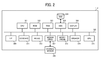
- FIG. 2 is an example of a hardware configuration of the electronic information terminal 1 of the first example embodiment.
- the server 2 can employ a hardware configuration similar to the hardware configuration of the electronic information terminal 1, in which some of the units may be changed or omitted for the server 2 as required.
- the electronic information terminal 1 includes, for example, a central processing unit (CPU) 301, a read only memory (ROM) 302, and a random access memory (RAM) 303.
- the CPU 301 controls the terminal as a whole.
- the ROM 302 stores programs such as initial program loader (IPL) to activate the CPU301.
- the RAM 303 is used as a working area of the CPU 301.
- the electronic information terminal 1 further includes, for example, a hard disk drive (HDD) 304, and a hard disk controller (HDC) 305.
- the HDD304 stores various data such as programs.
- the HDC 305 controls data reading and data writing of various data to the HDD 304 under the control of the CPU 301.
- the electronic information terminal 1 further includes, for example, a media drive 307 and a display 308.
- the media drive 307 controls data reading and data writing to a storage medium 306 such as a flash memory.
- the display 308 displays various information.
- the display 308 employs, for a touch panel display.
- the display 308 can be also used as operation device to operate the electronic information terminal 1.
- the electronic information terminal 1 further includes, for example, an interface (I/F) 309, a keyboard 311, a mouse 312, a microphone 313, a speaker 314, a graphics processing unit (GPU) 315 and a bus line 320.
- the I/F309 is used to communicate data via the communication network "N.”
- the keyboard 311 and the mouse 312 can be used to operate the electronic information terminal 1.
- the bus line 320 employs, for example, an address bus and data bus to connect the above described units electrically.
- Programs used for the electronic information terminal 1 and/or the server 2 are installable and executable formatted files, and the programs can be stored and distributed using computer readable storage medium such as the storage medium 306.
- FIG. 3 is a functional block diagram of the electronic information terminal 1 and the server 2 of the first example embodiment.
- the electronic information terminal 1 includes, for example, a touch panel display 101.
- the touch panel display 101 corresponding to the display 308 of FIG. 2 can be used as a display and an operation device.
- the operation to the electronic information terminal 1 can be performed by touching the touch panel display 101 using a hand, a finger, or a device such a touch pen and a mouse.
- the electronic information terminal 1 includes, for example, a first operation event receiver 102, an operation event cache 103 useable as a transmission-use memory or first memory, an operation event transmitter 104 useable as a transmitter or transmission unit, and a first network condition controller 105.
- the first operation event receiver 102 receives an operation event occurred by an operation to the touch panel display 101.
- the operation event cache 103 temporarily stores the operation event to be transmitted to the server 2.
- the operation event transmitter 104 transmits the operation event read out from the operation event cache 103 to the server 2.
- the first network condition controller 105 controls the condition of the communication network "N.” For example, the first network condition controller 105 performs connection processing and disconnection processing to the communication network "N," various information processing related to the network connection with the server 2, and monitors the network condition (connection/ disconnection, quality decease/quality increase).
- the electronic information terminal 1 further includes, for example, a stroke edition-condition display controller 106 (operation condition display controller).
- the stroke edition-condition display controller 106 displays an interface for stroke edition and a condition of being-edited stroke on the touch panel display 101 based on the operation event received from the touch panel display 101.
- the stroke edition-condition display controller 106 can be referred to a local feedback (LFB), and the stroke edition-condition display controller 106 can be used as an operation condition display controller.
- LFB local feedback
- the electronic information terminal 1 further includes, for example, an event receiver 107, an image receiver 108, and an image display controller 109.
- the event receiver 107 receives an event from a stroke-display-and-edit unit 203 of the server 2 via an event transmitter 204 of the server 2.
- the image receiver 108 receives an image from the server 2.
- the image display controller 109 displays the image received by the image receiver 108 on the touch panel display 101.
- the image receiver 108 is used as an image receiver, and the image display controller 109 is used as an image display controller.
- the server 2 includes, for example, a second operation event receiver 201, an operation event queue 202 useable as a reception-use memory or second memory, and a stroke-display-and-edit unit 203 useable as an image data generator.
- the second operation event receiver 201 used as an event receiver, receives the operation event.
- the operation event queue 202 temporarily stores operation events using a first-in-first-out memory.
- the stroke-display-and-edit unit 203 reads out the operation event from the operation event queue 202, and displays and edits stroke.
- the server 2 further includes, for example, an event transmitter 204 and a background image display unit 205.
- the event transmitter 204 transmits an event such as an image switching notice that occurs during the stroke edition to the electronic information terminal 1.
- the background image display unit 205 displays a background image.
- the server 2 further includes, for example, an image synthesizer 206 and an image transmitter 207.
- the image synthesizer 206 synthesizes the background image and stroke as an image such as a movie image, and encodes the image with a given format to generate the encoded image.
- the image transmitter 207 transmits the encoded image generated by the image synthesizer 206 to the electronic information terminal 1.
- the image synthesizer 206 can be used as an image synthesizer, and the image transmitter 207 can be used as an image transmitter.
- the server 2 further includes, for example, a second network condition controller 208 that controls the condition of the communication network "N.”
- the second network condition controller 208 performs connection processing and disconnection processing to the communication network "N," various information processing related to the network connection with the electronic information terminal 1, and monitors the network condition (connection/ disconnection, quality decease/quality increase).
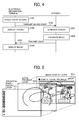
- FIG. 4 is a sequential chart illustrating a process of a basic operation by the electronic information terminal 1 and the server 2 of the first example embodiment.
- the basic operation is described using a mouse event as an example of the operation event.
- a mouse event occurs as the operation event (step S101).
- the first operation event receiver 102 receives the mouse event from the touch panel display 101, the mouse event can be stored in the operation event cache 103, the operation event transmitter 104 reads out the mouse event from the operation event cache 103, and the operation event transmitter 104 transmits the mouse event to the server 2 (step S102).
- the stroke edition-condition display controller 106 receives the mouse event from the first operation event receiver 102, and generates a stroke corresponding to the received mouse event (hereinafter, this generated stroke may be referred to a local feedback (LFB) stroke or a first image) and displays the stroke on the touch panel display 101 (step S103).
- this generated stroke may be referred to a local feedback (LFB) stroke or a first image
- the second operation event receiver 201 receives the mouse event from the event transmitter 104, and the stroke-display-and-edit unit 203 uses a stroke drawing application to generate to an image of stroke based on the received mouse event (hereinafter, this generated image may be referred to a second image) (step S201).
- this generated image may be referred to a second image
- the stroke-display-and-edit unit 203 generates the image of stroke based on the sequentially received mouse events.
- the image synthesizer 206 synthesizes a background image supplied from the background image display unit 205 and one or more images generated by the stroke drawing application to generate an image such as a movie image, and encodes the image with a given format (step S202).
- the image transmitter 207 transmits the generated encoded image to the electronic information terminal 1 (step S203).
- the image receiver 108 receives the encoded image, and the image display controller 109 decodes the encoded image and displays the image on the touch panel display 101 (step S104).
- the movie image may mean a movie image displaying a plurality of images continuously, and the movie image can be encoded by using a format such as H.264.
- the movie image transmitted from the server 2 to the electronic information terminal 1 is referred to an image.
- FIG. 5 illustrates an example of a layer structure of a screen displayable on the electronic information terminal 1.
- the screen image displayable on the electronic information terminal 1 can be configured with a plurality of layers such as an image-display layer 101a, a local feedback layer 101 and an operation-panel-display layer 101c.
- the image-display layer 101 a displays an image transmitted from the server 2.
- the local feedback layer 101b displays an interface for stroke edition and a condition of being-edited stroke.
- the operation-panel-display layer 101c displays, for example, a list of available commands.
- the touch panel display 101 of the electronic information terminal 1 displays a screen image that superimposes the image-display layer 101a, the local feedback layer 101 and the operation-panel-display layer 101c.
- FIG. 6 illustrates a schematic process of transmission of image by the server 2 of the first example embodiment.
- the image synthesizer 206 synthesizes each stroke generated by the stroke-display-and-edit unit 203, and a background image supplied from the background image display unit 205 to generate an image such as a movie image including one or more synthesized images. Further, the image synthesizer 206 further performs an encoding process to the movie image to encode the movie image with a given format such as H.264 (video compression coding method) and/or MPEG-4 (video compression coding method for portable terminals) to generate image data.
- the image transmitter 207 transmits the encoded image data to the electronic information terminal 1.
- the image receiver 108 receives the encoded image data and decodes the encoded image data.
- the image display controller 109 displays the decoded image data on the touch panel display 101.
- FIG. 7 illustrates an example of data structure of the operation events such as mouse events of the first example embodiment.
- Each of the mouse events includes information of an event name, event generation date, event transmission date to the server 2, coordinates of events, and operated or operation page.
- the coordinate information of event indicates a coordinate position of event on the touch panel display 101, and the coordinate position of event can be detected by a coordinate sensor of the touch panel display 101.
- the operation page indicates information of page position processed as an operation target when a background image supplied from the background image display unit 205 of the server 2 (see FIG. 6 ) is configured with a plurality of pages.
- a mouse event such as a stroke is drawn on page "1" from the electronic information terminal 1a while the electronic information terminal 1a is being disconnected from the communication network "N" and a background image transmitted from the server 2 is changed to the page "2" by the operation at another electronic information terminal 1b. If the electronic information terminal 1a is connected again to the communication network "N" and transmits the mouse event to the server 2, the server 2 can apply the mouse event to the correct operation page because the mouse event includes information of the operation page. Further, instead of the mouse event, Stylus events (Stylus_Down, Stylus_Move, Stylus_Up) can be used.
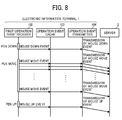
- FIG. 8 is a sequential chart illustrating a process of transmission of the mouse events of the first example embodiment.
- FIG. 8 is an example when the electronic information terminal 1 is connected to the communication network "N" normally.
- the mouse event occurs as the operation event.
- the operation event cache 103 temporarily stores the mouse event.
- the operation event transmitter 104 read outs the mouse events sequentially from the operation event cache 103, and transmits the mouse events to the server 2.
- the mouse event "MouseUp” occurs. Then, the operation event transmitter 104 transmits the mouse event "MouseUp” to the server 2.
- One stroke drawing operation is started by a pen down and is ended by a pen up. Therefore, the one stroke includes the mouse events "MouseDown, MouseMove and MouseUp.” These mouse events can be detected as a string of mouse events.
- the string of mouse events includes one MouseDown event, at least one MouseMove event, and one MouseUp event.
- the operation event transmitter 104 deletes the string of mouse events from the operation event cache 103.
- each of the one MouseDown event, at least one MouseMove event, and one MouseUp event is temporarily stored in the operation event cache 103 and then transmitted to the server 2 sequentially.
- the operation event transmitter 104 deletes the string of mouse events such as MouseDown, MouseMove, and MouseUp from the operation event cache 103.
- the second operation event receiver 201 receives the mouse events sequentially transmitted from the electronic information terminal 1, and temporarily stores the mouse events in the operation event queue 202.
- the stroke-display-and-edit unit 203 sequentially reads out the mouse events from the operation event queue 202, and generates stroke image data based on the mouse events.
- FIG. 9 is another sequential chart illustrating a process of transmission of the mouse events of the first example embodiment.
- the operation event transmitter 104 of the electronic information terminal 1 stores the mouse events in the operation event cache 103, and transmits the string of mouse events stored in the operation event cache 103 to the server 2 again from the first to last mouse events sequentially when the communication network "N" is re-connected with the electronic information terminal 1.
- the operation event occurs by an operation to the touch panel display 101
- the occurred operation event can be temporarily stored in the operation event cache 103 before the operation event is transmitted to the server 2. Since the condition of the communication network "N" is being monitored by the first network condition controller 105 constantly, the operation of the operation event transmitter 104 can be changed based on the condition of the communication network "N"
- the operation event transmitter 104 suspends the transmission of the mouse events to the server 2. If the operation to the touch panel display 101 is still continued during the disconnection with the communication network "N,” the mouse events occur, and the mouse events are stored sequentially in the operation event cache 103.
- the electronic information terminal 1 and the server 2 can be operated as follows. Specifically, since the operation event transmitter 104 of the electronic information terminal 1 cannot complete the transmission of the string of mouse events to the server 2, the operation event transmitter 104 does not perform a process of deleting the corresponding mouse events from the operation event cache 103.
- the stroke edition-condition display controller 106 displays an image based on the operation event received from the first operation event receiver 102 on the touch panel display 101, in which the operation event is generated on the electronic information terminal 1 but the operation event is no generated or reproduced on the server 2.
- the stroke-display-and-edit unit 203 deletes the incompletely received string of mouse events from the operation event queue 202, and image data is not generated for the incompletely received string of mouse events deleted by the stroke-display-and-edit unit 203.
- the incompletely received string of mouse events means that at least a part of a plurality of mouse events, which are used to generate one image such as stroke, is not transmitted to the server 2 due to the disconnection with the communication network "N,” and thereby the server 2 does not receive the complete set of the string of mouse events.
- the operation event transmitter 104 sequentially reads out the operation events from the operation event cache 103 and transmits the operation events to the server 2.
- the operation event transmitter 104 reads out the string of the operation events from the first (MouseDown event) to last mouse events sequentially, and transmits the string of the operation events to the server 2.
- the second operation event receiver 201 receives the mouse events transmitted from the electronic information terminal 1, and temporarily stores the mouse events in the operation event queue 202.
- the stroke-display-and-edit unit 203 sequentially reads out the mouse events from the operation event queue 202, and generates stroke image data based on the mouse events.
- FIG. 10 is a flow chart showing the steps of a process of transmitting the mouse events from the electronic information terminal 1 of the first example embodiment.
- the communication protocol employs transmission control protocol/internet protocol (TCP/IP).
- the operation event transmitter 104 extracts one mouse event from the operation event cache 103, in which the operation event transmitter 104 generates a copy of the mouse event of a transmission target from the mouse events stored in the operation event cache 103.
- the operation event transmitter 104 transmits the mouse event extracted from the operation event cache 103 to the server 2.
- the first network condition controller 105 checks whether a transmission of the mouse event has completed successfully each time the operation event transmitter 104 transmits the mouse event. Specifically, the first network condition controller 105 checks whether a packet including a normal confirmation response "ACK (acknowledge)" is returned from the server 2 within a given time period after the operation event transmitter 104 transmits the mouse event data to the server 2.
- step S5 the first network condition controller 105 determines that the transmission of the operation events has completed successfully (step S5: YES), and the sequence proceeds to step S7.
- step S7 the operation event transmitter 104 checks whether the string of the operation events is completely transmitted.
- step S7 If an operation event not-yet-transmitted exists in the string of the operation events (step S7: NO), the sequence returns to step S1. If the string of the operation events are completely transmitted (step S7: YES), the operation event transmitter 104 deletes the string of the operation events from the operation event cache 103 (step S9). If a to-be-transmitted new string of operation events exists, the sequence returns to step S1 and the subsequent steps are performed again.
- the first network condition controller 105 determines that the transmission of the operation events has failed (step S5: NO), and then the sequence proceeds to step S11.
- the operation event transmitter 104 suspends the transmission of the operation events.
- the first network condition controller 105 check the connection with the server 2. Specifically, the first network condition controller 105 transmits a "SYN" packet having a SYN (synchronize) flag of 1 requesting the connection to the server 2.
- the first network condition controller 105 checks whether a SYN/ACK packet having the SYN flag of "1" and ACK of flag "1" is returned from the server 2 within the given time period.
- step S15: NO the first network condition controller 105 performs step S13 periodically. If the SYN/ACK packet is returned from the server 2within the given time period (step S15: YES), the sequence returns to step S1 and the subsequent steps are performed.
- the operation event transmitter 104 re-transmits the string of mouse events starting from the first (MouseDown event) to last mouse events sequentially to the server 2.
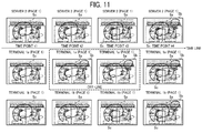
- FIG. 11 schematically illustrates an image processing when the network connection between the electronic information terminal 1 and the server 2 is disconnected.
- the image processing system includes one server 2, and two electronic information terminals 1a and 1b.
- FIG. 11 illustrates an example case that a stroke is drawn on the touch panel display 101 of the electronic information terminal 1a (one terminal or first terminal), and the stroke data is reproduced on the touch panel display 101 of the electronic information terminal 1b (another terminal or first terminal) via the server 2.
- the screens of the server 2 and the two electronic information terminals 1a and 1b are-synchronized one to another, in which a stroke Sa is drawn on an image of the page "1" used as a background image.
- the server 2 transmits an image drawn with the stroke Sa, the stroke Sc and the stroke Sb to the two electronic information terminals 1a and 1b, in which the screens of the server 2 and the two electronic information terminals 1a and 1b are synchronized one to another, and the strokes Sa, Sb and Sc are drawn on the screens of the server 2 and the two electronic information terminals 1a and 1b.
- FIG. 12 schematically illustrates another image processing when the network connection between the electronic information terminal 1 and the server 2 is disconnected.
- FIG. 12 schematically illustrates an image processing when the electronic information terminal 1 switches or changes a display-use page while the communication network "N" is being disconnected.
- the screens of the server 2 and the two electronic information terminals 1a and 1b are synchronized one to another, in which a stroke Sa is drawn on an image of the page "1" used as a background image.
- the server 2 At the time point "t3,” it is assumed that the an event to switch the display-use page from page “1" to page "2" occurs at the electronic information terminal 1b, and this event is transmitted to the server 2. Then, the server 2 generates an image displaying the page "2" based on the event received from the electronic information terminal 1b, and transmits an image to each of the two electronic information terminals 1a and 1b. Since the electronic information terminal 1b is at an on-line condition, the electronic information terminal 1b receives the image, and the screen of the server 2 and the screen of electronic information terminal 1b are synchronized one to another, but since the electronic information terminal 1a at the off-line condition, the display switching to the page "2" is not reproduced on the screen of the electronic information terminal 1a.
- the electronic information terminal 1a can transmit data of the stroke Sb drawn on the page “1" at the time point "t2" to the server 2, in which the server 2 generates image data including the data of the stroke Sb drawn on the page "1" by the electronic information terminal 1a.
- the screen is displaying the page "2" at the time point "t4”
- the data of the stroke Sb is not reproduced the screen visually at the time point "t4.”
- the electronic information terminal 1 of the first example embodiment has the local feedback (LFB) capability. Therefore, even if the electronic information terminal 1 is disconnected from the communication network "N," various operation events such as mouse events drawn on the electronic information terminal 1 can be displayed on the touch panel display.
- LFB local feedback
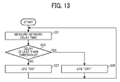
- FIG. 13 is a flow chart showing the steps of a process of ON-OFF control of LFB capability.
- the first network condition controller 105 measures a round trip time RTT as the network delay time. Specifically, the first network condition controller 105 transmit a request of data transfer to the server 2, and measures a return time to receive a reply from the server 2.
- the first network condition controller 105 checks whether the round trip time RTT (i.e., network delay time) is less than a given threshold. If the round trip time RTT is less than the given threshold (i.e., network delay is small) (step S23: YES), the first network condition controller 105 transmits a command signal to deactivate the operation to the stroke edition-condition display controller 106 to set the LFB capability at OFF (step S25).
- the first network condition controller 105 transmits a command signal to activate the operation to the stroke edition-condition display controller 106 to set the LFB capability ON (step S27).
- the first network condition controller 105 can measure the round trip time RTT for the communication network "N" periodically.
- the LFB capability when the network delay time is too small, the LFB capability is deactivated (i.e., OFF), and thereby the processing load of the electronic information terminal 1 can be reduced.
- the LFB capability is activated (i.e., ON), and thereby the usability can be enhanced.
- the image data is not generated because the received string of mouse events is incomplete.
- the stroke-display-and-edit unit 203 can be configured to generate image data based on the already received mouse events, which a part of string of mouse events received incompletely. With employing this processing, the stroke data just before the electronic information terminal 1 is disconnected from the communication network "N" can be reproduced as the image data.
- a conventional transmission system can delete a stroke temporarily displayed on a display when a given time elapses as disclosed in JP-2015-056844-A .
- JP-2015-056844-A the stroke temporarily displayed on the display of the electronic information terminal 1 cannot be deleted when the page switching occurs.
- FIG. 14 illustrates this situation of conventional arts.
- the image processing at of the server is illustrated at the upper part of FIG. 14
- the image displaying at the electronic information terminal is illustrated at the lower part of FIG. 14 .
- the server receives a page switching request from another electronic information terminal, and then the server 2 switches the image displaying from the state 1 to the state 2 as indicated by a dot line.
- the server displays an image 2 at the state 1, and transmits the image 2 to one electronic information terminal used as a transmission destination, and the electronic information terminal 1 also displays the image 2.
- the electronic information terminal 1 also displays the image 2. If a user (first user) of the electronic information terminal inputs a stroke when the image 2 is being displayed, the stroke is temporarily displayed on the screen of the electronic information terminal, which means this stroke is temporarily drawn on a LFB layer, in which the stroke is drawn from one of the curved line displayed as the image 2.
- the server switches the image displaying from the image 2 to the image 3 as indicated in the state 2 in the upper part of the FIG. 14 .
- the server transmits the image 3 to the electronic information terminal of the first user, and then the image 3 is displayed on the screen of the electronic information terminal of the first user that has received the image 3, in which the image 3 is drawn on the image-display layer 101 a of the electronic information terminal of the first user.
- the temporarily-displayed stroke is displayed on the LFB layer 101b different from the image-display layer 101a in the electronic information terminal of the first user. Therefore, when the electronic information terminal of the first user becomes the state 2, the image 3 drawn on the image-display layer 101a and the stroke temporarily-displayed on the LFB layer 101 bare superimposed with each other, and thereby a screen image that combines the stroke image drawn the image 2, and the image 3 may be displayed.
- the image processing system of the second example embodiment can be configured as follows. For example, as illustrated in FIG. 12 , when the image transmitted from the server 2 is changed from the page "1" to the page "2" by operating another electronic information terminal 1b, the server 2 transmits an image switching notice to all of the electronic information terminals 1 including the electronic information terminal 1a. When the electronic information terminal 1 receives the image switching notice, the LFB stroke drawn as the first image on the electronic information terminal 1 is deleted.
- the background image display unit 205 used as the background image switching unit switches the screen from the page "2" to the page "3" (step S41).
- the "background image” is an image displayed on one layer different from a layer displaying the second image (e.g., stroke). For example, the "background image” displayed on one layer under the layer displaying the second image (e.g., stroke).
- the server 2 transmits the image switching notice to all of the electronic information terminals 1 via the event transmitter 204 (step S42).
- the background image display unit 205 of the server 2 performs a switching operation of the background image (step S43).
- step S52 A description is given of a process of deleting LFB stroke at the electronic information terminal 1 with reference to FIG. 16 .
- the stroke edition-condition display controller 106 deletes the LFB stroke (step S52).
- the second example embodiment even if a plurality of pages is retained and an application image that can write a stroke is transmitted for each of the pages, unintended image display at the electronic information terminal 1 can be prevented.
- the background image is switched from a first background image to a second background image
- the stroke temporarily drawn on the first background image displayed on the electronic information terminal 1 before the image switching and the second background image displayed on the electronic information terminal 1 after the image switching are not mixed at the electronic information terminal 1, and thereby the stroke temporarily drawn on the first background image are not displayed with the second background image.
- the electronic information terminal 1 is connectable with the image processing apparatus such as server 2 via the communication network N.
- the electronic information terminal 1 includes, for example, the display such as the touch panel display 101, the first memory such as the transmission-use memory (operation event cache 103) to temporarily store stroke data generated by an operation event such as mouse event to the display, the first network condition controller 105 to detect a condition of the communication network N, and the transmitter such as the operation event transmitter 104 to read out the stroke data from the first memory and to transmit the stroke data to the image processing apparatus via the communication network N based on the condition of the communication network N detected by the first network condition controller 105.
- the display such as the touch panel display 101
- the first memory such as the transmission-use memory (operation event cache 103) to temporarily store stroke data generated by an operation event such as mouse event to the display
- the first network condition controller 105 to detect a condition of the communication network N
- the transmitter such as the operation event transmitter 104 to read out the stroke data from the first memory and to transmit the stroke data to the image processing apparatus via the
- the transmitter reads out the stroke data from the first memory and to transmit the stroke data to the image processing apparatus based on the condition of the communication network N detected by the first network condition controller 105. Therefore, the data vanishing such as partial data loss of stroke data can be avoided.
- the mouse events for drawing the image are used as an example of the stroke data, but not limited hereto.
- the stroke data that is used to erase a part or entire of drawn image can be used.
- the electronic information terminal 1 includes, for example the operation condition display controller such as the stroke edition-condition display controller 106 to display the first image, generated from the stroke data, on the display such as the touch panel display 101.
- the operation condition display controller such as the stroke edition-condition display controller 106 to display the first image, generated from the stroke data, on the display such as the touch panel display 101.
- the electronic information terminal 1 uses an external image processing apparatus to perform the image processing of the stroke data, and then receives the second image generated by the external image processing apparatus and displays the second image on the electronic information terminal 1, the display of the second image may be delayed due to the network delay.
- the operation condition display controller can perform the local feedback (LFB) processing that generates the first image from the stroke data and displays the first image on the touch panel display 101. Therefore, the electronic information terminal 1 can display the image to a user without delaying the image displaying timing.
- LFB local feedback
- the electronic information terminal 1 includes, for example, the image receiver 108 that receives the image generated from the stroke data by the image processing apparatus such as the server 2 via the communication network "N," and the image display controller 109 that superimposes the image received from the image processing apparatus on the first image, and displays the superimposed image.
- the electronic information terminal 1 can receive and display the image including the second image generated by the image processing apparatus, and the first image generated by the operation condition display controller can be superimposed with the image generated by the image processing apparatus, and the superimposed image can be displayed. Therefore, the electronic information terminal 1 can display the image to a user without causing uncomfortableness.
- the first network condition controller 105 further measures a communication network delay time, and determines whether the measured communication network delay time is equal to or greater than a given threshold.
- the operation condition display controller (stroke edition-condition display controller 106) displays the first image on the display such as the touch panel display 101, and when the measured communication network delay time is less than the given threshold, the operation condition display controller (stroke edition-condition display controller 106) stops a display of the first image on the display such as the touch panel display 101.
- the operation condition display controller can perform the LFB processing that generates the first image and displays the first image on the touch panel display 101, with which the first image based on the stroke data can be displayed real time even if the network delay is greater.
- the LFB processing increases the processing load of the electronic information terminal 1.
- the operation condition display controller deactivates (e.g., stops) the displaying of the first image when the network delay is small, with which the processing load of the electronic information terminal 1 can be reduced.
- the first network condition controller 105 detects the disconnection with the communication network "N” while the transmitter such as the operation event transmitter 104 is transmitting the string of stroke data, and then the first network condition controller 105 detects the re-connection with the communication network "N.”
- the transmitter transmits the string of stroke data from the first to last, which were transmitted when the disconnection with the communication network "N” occurred, to the image processing apparatus such as the server 2.
- the transmitter reads out the string of stroke data from the transmission-use memory and transmits the string of stroke data when the re-connection with the communication network "N” occurs. Therefore, the string of stroke data can be transmitted completely even if the electronic information terminal 1 is disconnected from the communication network "N" while the string of stroke data is being transmitted.
- the transmitter deletes the string of stroke data from the transmission-use memory such as the operation event cache 103.
- the transmission-use memory stores the string of stroke data until the transmission of the string of stroke data is completed. Therefore, the string of stroke data can be transmitted completely even if the electronic information terminal 1 is disconnected from the communication network "N" while the string of stroke data is being transmitted.
- the image processing apparatus such as the server 2 connectable with the electronic information terminal 1 via the communication network N includes, for example, the reception-use memory such as the operation event queue 202 to temporarily store stroke data sequentially received from the electronic information terminal 1, and the second image generator such as the stroke-display-and-edit unit 203 to generate the second image based on the string of stroke data stored in the second memory.
- the second image generator 203 generates the second image when the string of stroke data is completely stored in the second memory such as the reception-use memory 202.
- the second image generator generates the second image after the string of stroke data is completely received. Therefore, the data vanishing such as partial data loss of stroke data can be avoided, and the second image can be drawn completely based on the string of stroke data.
- the image processing apparatus such as the server 2 includes, for example, the second network condition controller 208 that controls the condition of the communication network "N.”
- the second image generator such as the stroke-display-and-edit unit 203 deletes the incompletely received string of stroke data from the reception-use memory such as the operation event queue 202.
- the second image generator can delete the incompletely received string of stroke data from the reception-use memory. Therefore, the second image generator can receive the string of stroke data completely when the string of stroke data is transmitted again.
- the image processing apparatus such as the server 2 includes, for example, the second network condition controller 208 that controls the condition of the communication network "N.”
- the second network condition controller 208 detects the disconnection with the communication network "N" while the string of stroke data is being received
- the second image generator such as the stroke-display-and-edit unit 203 generates the second image based on the string of stroke data incompletely stored in the reception-use memory such as the operation event queue 202.
- the stroke data just before the electronic information terminal 1 is disconnected from the communication network "N" can be reproduced as the second image at the image processing apparatus.
- the image processing system includes, for example, the electronic information terminal 1 and the image processing apparatus such as the server 2 connectable with the electronic information terminal 1 via the communication network "N.”
- the electronic information terminal 1 includes, for example, the display such as the touch panel display 101, the transmission-use memory such as the operation event cache 103 (first memory) to temporarily store stroke data generated by an operation event such as the mouse event to the display such as the touch panel display 101, the first network condition controller 105 to detect a condition of the communication network "N," the transmitter such as the operation event transmitter 104 to read out the stroke data from the transmission-use memory and to transmit the stroke data to the image processing apparatus via the communication network "N" based on the condition of the communication network "N” detected by the first network condition controller (105), the operation condition display controller such as the stroke edition-condition display controller 106 to display the first image, generated from the stroke data, on the display, the image display controller 109 to display an image received from the image processing apparatus a layer different from a layer displaying the first image, in which the image received from the image processing apparatus is displayed on the layer under the layer displaying the first image.
- the display such as the touch panel display 101
- the transmission-use memory such as the operation event cache
- the image processing apparatus includes, for example, the reception-use memory such as the operation event queue 202 to temporarily store stroke data sequentially received from the electronic information terminal 1 via the communication network "N" as a string of stroke data; the second image generator such as the stroke-display-and-edit unit 203 to generate the second image based on the string of stroke data stored in the reception-use memory such as the operation event queue 202 (second memory), the image synthesizer 206 to synthesize the second image displayed on a layer and a background image to be displayed on a layer, different from the layer displaying the second image, as a synthesized image, in which the background image is displayed on the layer under the layer displaying the second image, the display unit such as the background image display unit 205 to display the synthesized image generated by the image synthesizer 206 or the background image, the image transmitter 207 to transmit the synthesized image or the background image displayed by the display unit to the electronic information terminal 1, the background image switching unit such as the background image display unit 205 to switch the background image displayed by the
- the operation condition display controller deletes the first image when the electronic information terminal 1 receives the image switching notice from the image processing apparatus.
- the background image is switched from a first background image to a second background image (i.e., page switching)
- the stroke temporarily drawn on the first background image displayed on the electronic information terminal 1 before the image switching and the second background image displayed on the electronic information terminal 1 after the image switching are not mixed at the electronic information terminal 1, and thereby the stroke temporarily drawn on the first background image are not displayed with the second background image.
- the electronic information terminal 1 is connectable with the image processing apparatus such as server 2 via the communication network N.
- the electronic information terminal 1 includes, for example, the display such as the touch panel display 101, the transmission-use memory such as the operation event cache 103 (first memory) to temporarily store stroke data generated by an operation event such as mouse event to the display, the first network condition controller 105 to detect a condition of the communication network N, the transmitter such as the operation event transmitter 104 to read out the stroke data from the first memory and to transmit the stroke data to the image processing apparatus via the communication network N based on the condition of the communication network N detected by the first network condition controller 105, the operation condition display controller such as the stroke edition-condition display controller 106 to display the first image, generated from the stroke data, on the display, and the image display controller 109 to display an image received from the image processing apparatus on a layer different from a layer displaying the first image, in which the image received from the image processing apparatus is displayed on the layer under the layer displaying the first image.
- the display such as the touch panel display 101
- the operation condition display controller deletes the first image when the operation condition display controller receives an image switching notice, from the image processing apparatus, that indicates that a background image displayed on a layer different from a layer displaying a second image generated from the stroke data transmitted from the transmitter and displayed by the display unit of the image processing apparatus is switched to another background image.
- the stroke temporarily drawn on the first background image displayed on the electronic information terminal 1 before the image switching and the second background image displayed on the electronic information terminal 1 after the image switching are not mixed at the electronic information terminal 1, and thereby the stroke temporarily drawn on the first background image are not displayed with the second background image.
- the image processing system includes the electronic information terminal 1 of any of the above configurations and the image processing apparatus such as the server 2 of any of the above configurations.
- the effect of the electronic information terminal 1 of any of the above configurations and the image processing apparatus such as the server 2 of any of the above configurations can be attained.
- the data vanishing such as partial data loss of stroke data can be avoided.
- the above described example embodiments can be applied to the image processing apparatus that processes the transmission stroke data, and the image processing system including the electronic information terminal and the image processing apparatus.
- the transmitter since the transmitter reads out the stroke data from the transmission-use memory and then transmits the stroke data based on the condition of the communication network detected by the network condition controller, the data vanishing such as partial data loss of stroke data can be avoided.
- the present invention can be implemented in any convenient form, for example using dedicated hardware, or a mixture of dedicated hardware and software.
- the present invention may be implemented as computer software implemented by one or more networked processing apparatuses.
- the network can comprise any conventional terrestrial or wireless communications network, such as the Internet.
- the processing apparatuses can compromise any suitably programmed apparatuses such as a general purpose computer, personal digital assistant, mobile telephone (such as a WAP or 3G-compliant phone) and so on.
Landscapes
- Engineering & Computer Science (AREA)
- Signal Processing (AREA)
- Multimedia (AREA)
- Theoretical Computer Science (AREA)
- General Physics & Mathematics (AREA)
- Physics & Mathematics (AREA)
- Computer Networks & Wireless Communication (AREA)
- Computer Vision & Pattern Recognition (AREA)
- Human Computer Interaction (AREA)
- General Engineering & Computer Science (AREA)
- Business, Economics & Management (AREA)
- General Business, Economics & Management (AREA)
- Controls And Circuits For Display Device (AREA)
Applications Claiming Priority (2)
| Application Number | Priority Date | Filing Date | Title |
|---|---|---|---|
| JP2015142323 | 2015-07-16 | ||
| JP2016119676A JP2017027589A (ja) | 2015-07-16 | 2016-06-16 | 電子情報端末、画像処理装置、及び画像処理システム |
Publications (1)
| Publication Number | Publication Date |
|---|---|
| EP3119084A1 true EP3119084A1 (de) | 2017-01-18 |
Family
ID=56896314
Family Applications (1)
| Application Number | Title | Priority Date | Filing Date |
|---|---|---|---|
| EP16179458.1A Withdrawn EP3119084A1 (de) | 2015-07-16 | 2016-07-14 | Elektronisches informationsendgerät, bildverarbeitungsvorrichtung und bildverarbeitungssystem |
Country Status (2)
| Country | Link |
|---|---|
| US (1) | US20170017455A1 (de) |
| EP (1) | EP3119084A1 (de) |
Families Citing this family (2)
| Publication number | Priority date | Publication date | Assignee | Title |
|---|---|---|---|---|
| US10852934B2 (en) * | 2017-12-21 | 2020-12-01 | The Boeing Company | Latency compensation in coupled processor systems |
| JP7852320B2 (ja) | 2022-03-18 | 2026-04-28 | 株式会社リコー | 機器システム、情報処理方法 |
Citations (6)
| Publication number | Priority date | Publication date | Assignee | Title |
|---|---|---|---|---|
| JP2002278958A (ja) * | 2001-03-16 | 2002-09-27 | Mitsubishi Electric Corp | 携帯端末装置および入力文字処理装置 |
| WO2009151940A2 (en) | 2008-06-14 | 2009-12-17 | Microsoft Corporation | Techniques to manage a whiteboard for multimedia conference events |
| US20110320925A1 (en) * | 2010-06-29 | 2011-12-29 | Piersol Kurt W | User interface with inbox mode and document mode for single input work flow routing |
| JP2015056844A (ja) | 2013-09-13 | 2015-03-23 | 株式会社リコー | 通信端末及び通信方法 |
| US20160149976A1 (en) * | 2014-11-26 | 2016-05-26 | Mototsugu Emori | Electronic information terminal, image processing apparatus, and information processing method |
| JP2016110603A (ja) * | 2014-11-26 | 2016-06-20 | 株式会社リコー | 電子情報端末、画像処理装置、及び画像処理システム |
Family Cites Families (4)
| Publication number | Priority date | Publication date | Assignee | Title |
|---|---|---|---|---|
| US9684484B2 (en) * | 2013-05-29 | 2017-06-20 | Sonos, Inc. | Playback zone silent connect |
| JP2015106778A (ja) * | 2013-11-29 | 2015-06-08 | ブラザー工業株式会社 | プログラム、通信端末装置及び遠隔会議方法 |
| JP6468712B2 (ja) * | 2014-03-28 | 2019-02-13 | 大和ハウス工業株式会社 | 通信ユニット |
| US9613263B2 (en) * | 2015-02-27 | 2017-04-04 | Lenovo (Singapore) Pte. Ltd. | Ink stroke grouping based on stroke attributes |
-
2016
- 2016-07-13 US US15/209,222 patent/US20170017455A1/en not_active Abandoned
- 2016-07-14 EP EP16179458.1A patent/EP3119084A1/de not_active Withdrawn
Patent Citations (6)
| Publication number | Priority date | Publication date | Assignee | Title |
|---|---|---|---|---|
| JP2002278958A (ja) * | 2001-03-16 | 2002-09-27 | Mitsubishi Electric Corp | 携帯端末装置および入力文字処理装置 |
| WO2009151940A2 (en) | 2008-06-14 | 2009-12-17 | Microsoft Corporation | Techniques to manage a whiteboard for multimedia conference events |
| US20110320925A1 (en) * | 2010-06-29 | 2011-12-29 | Piersol Kurt W | User interface with inbox mode and document mode for single input work flow routing |
| JP2015056844A (ja) | 2013-09-13 | 2015-03-23 | 株式会社リコー | 通信端末及び通信方法 |
| US20160149976A1 (en) * | 2014-11-26 | 2016-05-26 | Mototsugu Emori | Electronic information terminal, image processing apparatus, and information processing method |
| JP2016110603A (ja) * | 2014-11-26 | 2016-06-20 | 株式会社リコー | 電子情報端末、画像処理装置、及び画像処理システム |
Non-Patent Citations (1)
| Title |
|---|
| MOTOTSUGU EMORI: "JP20014-239023", 15 March 2016 (2016-03-15), XP055325232, Retrieved from the Internet <URL:http://portal.uspto.gov/pair/PublicPair> [retrieved on 20161201] * |
Also Published As
| Publication number | Publication date |
|---|---|
| US20170017455A1 (en) | 2017-01-19 |
Similar Documents
| Publication | Publication Date | Title |
|---|---|---|
| US10419618B2 (en) | Information processing apparatus having whiteboard and video conferencing functions | |
| CN111803940B (zh) | 游戏的处理方法、装置、电子设备及计算机可读存储介质 | |
| JP4246528B2 (ja) | 切替器 | |
| US10142413B2 (en) | Information processing apparatus, information processing system, and communication control method | |
| US20150201085A1 (en) | Seamlessly transferring a communication | |
| US9293108B2 (en) | Transmission apparatus and system of using the same | |
| US9596435B2 (en) | Distribution control apparatus, distribution control method, and computer program product | |
| US20150149957A1 (en) | Method and system for wirelessly controlling image display | |
| KR101989016B1 (ko) | 전자장치에서 영상통화중 파일 전송 방법 및 장치 | |
| US10754606B2 (en) | Image processing apparatus and image processing system | |
| US20150029196A1 (en) | Distribution management apparatus | |
| JP2013113916A (ja) | 表示制御装置、画像表示システム、表示制御方法およびプログラム | |
| JP2015056030A (ja) | 画像処理装置および画像処理システム | |
| CN108710480A (zh) | 一种文档共享和文档控制的方法和系统 | |
| US20140089812A1 (en) | System, terminal apparatus, and image processing method | |
| EP3119084A1 (de) | Elektronisches informationsendgerät, bildverarbeitungsvorrichtung und bildverarbeitungssystem | |
| US10148708B2 (en) | Electronic information terminal, image processing apparatus, and information processing method | |
| WO2017138233A1 (ja) | 画像処理装置、画像処理システム及び画像処理方法 | |
| JP6492723B2 (ja) | 電子情報端末、画像処理装置、及び画像処理システム | |
| US20080036695A1 (en) | Image display device, image display method and computer readable medium | |
| JP2007328594A (ja) | サーバ装置、並びにその制御命令処理方法及び制御命令処理プログラム、端末装置 | |
| CN101873460A (zh) | 一种基于显示分层的系统级多媒体功能扩展方法 | |
| WO2024000487A1 (zh) | 用于投屏的终端、系统及方法、存储介质、电子设备 | |
| US9525901B2 (en) | Distribution management apparatus for distributing data content to communication devices, distribution system, and distribution management method | |
| JP4634499B2 (ja) | 画像表示方法及び画像表示プログラム |
Legal Events
| Date | Code | Title | Description |
|---|---|---|---|
| PUAI | Public reference made under article 153(3) epc to a published international application that has entered the european phase |
Free format text: ORIGINAL CODE: 0009012 |
|
| 17P | Request for examination filed |
Effective date: 20160714 |
|
| AK | Designated contracting states |
Kind code of ref document: A1 Designated state(s): AL AT BE BG CH CY CZ DE DK EE ES FI FR GB GR HR HU IE IS IT LI LT LU LV MC MK MT NL NO PL PT RO RS SE SI SK SM TR |
|
| AX | Request for extension of the european patent |
Extension state: BA ME |
|
| STAA | Information on the status of an ep patent application or granted ep patent |
Free format text: STATUS: THE APPLICATION IS DEEMED TO BE WITHDRAWN |
|
| 18D | Application deemed to be withdrawn |
Effective date: 20170719 |