EP3118698A1 - Machine tool control & measurement system - Google Patents
Machine tool control & measurement system Download PDFInfo
- Publication number
- EP3118698A1 EP3118698A1 EP16178305.5A EP16178305A EP3118698A1 EP 3118698 A1 EP3118698 A1 EP 3118698A1 EP 16178305 A EP16178305 A EP 16178305A EP 3118698 A1 EP3118698 A1 EP 3118698A1
- Authority
- EP
- European Patent Office
- Prior art keywords
- workpiece
- machine tool
- position sensor
- sensor system
- material thickness
- Prior art date
- Legal status (The legal status is an assumption and is not a legal conclusion. Google has not performed a legal analysis and makes no representation as to the accuracy of the status listed.)
- Withdrawn
Links
Images


Classifications
-
- G—PHYSICS
- G01—MEASURING; TESTING
- G01B—MEASURING LENGTH, THICKNESS OR SIMILAR LINEAR DIMENSIONS; MEASURING ANGLES; MEASURING AREAS; MEASURING IRREGULARITIES OF SURFACES OR CONTOURS
- G01B17/00—Measuring arrangements characterised by the use of infrasonic, sonic or ultrasonic vibrations
- G01B17/02—Measuring arrangements characterised by the use of infrasonic, sonic or ultrasonic vibrations for measuring thickness
-
- G—PHYSICS
- G05—CONTROLLING; REGULATING
- G05B—CONTROL OR REGULATING SYSTEMS IN GENERAL; FUNCTIONAL ELEMENTS OF SUCH SYSTEMS; MONITORING OR TESTING ARRANGEMENTS FOR SUCH SYSTEMS OR ELEMENTS
- G05B19/00—Programme-control systems
- G05B19/02—Programme-control systems electric
- G05B19/18—Numerical control [NC], i.e. automatically operating machines, in particular machine tools, e.g. in a manufacturing environment, so as to execute positioning, movement or co-ordinated operations by means of programme data in numerical form
- G05B19/401—Numerical control [NC], i.e. automatically operating machines, in particular machine tools, e.g. in a manufacturing environment, so as to execute positioning, movement or co-ordinated operations by means of programme data in numerical form characterised by control arrangements for measuring, e.g. calibration and initialisation, measuring workpiece for machining purposes
-
- B—PERFORMING OPERATIONS; TRANSPORTING
- B23—MACHINE TOOLS; METAL-WORKING NOT OTHERWISE PROVIDED FOR
- B23Q—DETAILS, COMPONENTS, OR ACCESSORIES FOR MACHINE TOOLS, e.g. ARRANGEMENTS FOR COPYING OR CONTROLLING; MACHINE TOOLS IN GENERAL CHARACTERISED BY THE CONSTRUCTION OF PARTICULAR DETAILS OR COMPONENTS; COMBINATIONS OR ASSOCIATIONS OF METAL-WORKING MACHINES, NOT DIRECTED TO A PARTICULAR RESULT
- B23Q15/00—Automatic control or regulation of feed movement, cutting velocity or position of tool or work
- B23Q15/007—Automatic control or regulation of feed movement, cutting velocity or position of tool or work while the tool acts upon the workpiece
- B23Q15/14—Control or regulation of the orientation of the tool with respect to the work
-
- B—PERFORMING OPERATIONS; TRANSPORTING
- B23—MACHINE TOOLS; METAL-WORKING NOT OTHERWISE PROVIDED FOR
- B23Q—DETAILS, COMPONENTS, OR ACCESSORIES FOR MACHINE TOOLS, e.g. ARRANGEMENTS FOR COPYING OR CONTROLLING; MACHINE TOOLS IN GENERAL CHARACTERISED BY THE CONSTRUCTION OF PARTICULAR DETAILS OR COMPONENTS; COMBINATIONS OR ASSOCIATIONS OF METAL-WORKING MACHINES, NOT DIRECTED TO A PARTICULAR RESULT
- B23Q15/00—Automatic control or regulation of feed movement, cutting velocity or position of tool or work
- B23Q15/20—Automatic control or regulation of feed movement, cutting velocity or position of tool or work before or after the tool acts upon the workpiece
- B23Q15/22—Control or regulation of position of tool or workpiece
-
- B—PERFORMING OPERATIONS; TRANSPORTING
- B23—MACHINE TOOLS; METAL-WORKING NOT OTHERWISE PROVIDED FOR
- B23Q—DETAILS, COMPONENTS, OR ACCESSORIES FOR MACHINE TOOLS, e.g. ARRANGEMENTS FOR COPYING OR CONTROLLING; MACHINE TOOLS IN GENERAL CHARACTERISED BY THE CONSTRUCTION OF PARTICULAR DETAILS OR COMPONENTS; COMBINATIONS OR ASSOCIATIONS OF METAL-WORKING MACHINES, NOT DIRECTED TO A PARTICULAR RESULT
- B23Q17/00—Arrangements for observing, indicating or measuring on machine tools
- B23Q17/20—Arrangements for observing, indicating or measuring on machine tools for indicating or measuring workpiece characteristics, e.g. contour, dimension, hardness
-
- B—PERFORMING OPERATIONS; TRANSPORTING
- B23—MACHINE TOOLS; METAL-WORKING NOT OTHERWISE PROVIDED FOR
- B23Q—DETAILS, COMPONENTS, OR ACCESSORIES FOR MACHINE TOOLS, e.g. ARRANGEMENTS FOR COPYING OR CONTROLLING; MACHINE TOOLS IN GENERAL CHARACTERISED BY THE CONSTRUCTION OF PARTICULAR DETAILS OR COMPONENTS; COMBINATIONS OR ASSOCIATIONS OF METAL-WORKING MACHINES, NOT DIRECTED TO A PARTICULAR RESULT
- B23Q17/00—Arrangements for observing, indicating or measuring on machine tools
- B23Q17/22—Arrangements for observing, indicating or measuring on machine tools for indicating or measuring existing or desired position of tool or work
- B23Q17/2233—Arrangements for observing, indicating or measuring on machine tools for indicating or measuring existing or desired position of tool or work for adjusting the tool relative to the workpiece
-
- B—PERFORMING OPERATIONS; TRANSPORTING
- B64—AIRCRAFT; AVIATION; COSMONAUTICS
- B64F—GROUND OR AIRCRAFT-CARRIER-DECK INSTALLATIONS SPECIALLY ADAPTED FOR USE IN CONNECTION WITH AIRCRAFT; DESIGNING, MANUFACTURING, ASSEMBLING, CLEANING, MAINTAINING OR REPAIRING AIRCRAFT, NOT OTHERWISE PROVIDED FOR; HANDLING, TRANSPORTING, TESTING OR INSPECTING AIRCRAFT COMPONENTS, NOT OTHERWISE PROVIDED FOR
- B64F5/00—Designing, manufacturing, assembling, cleaning, maintaining or repairing aircraft, not otherwise provided for; Handling, transporting, testing or inspecting aircraft components, not otherwise provided for
- B64F5/10—Manufacturing or assembling aircraft, e.g. jigs therefor
-
- G—PHYSICS
- G05—CONTROLLING; REGULATING
- G05B—CONTROL OR REGULATING SYSTEMS IN GENERAL; FUNCTIONAL ELEMENTS OF SUCH SYSTEMS; MONITORING OR TESTING ARRANGEMENTS FOR SUCH SYSTEMS OR ELEMENTS
- G05B19/00—Programme-control systems
- G05B19/02—Programme-control systems electric
- G05B19/18—Numerical control [NC], i.e. automatically operating machines, in particular machine tools, e.g. in a manufacturing environment, so as to execute positioning, movement or co-ordinated operations by means of programme data in numerical form
- G05B19/402—Numerical control [NC], i.e. automatically operating machines, in particular machine tools, e.g. in a manufacturing environment, so as to execute positioning, movement or co-ordinated operations by means of programme data in numerical form characterised by control arrangements for positioning, e.g. centring a tool relative to a hole in the workpiece, additional detection means to correct position
-
- G—PHYSICS
- G05—CONTROLLING; REGULATING
- G05B—CONTROL OR REGULATING SYSTEMS IN GENERAL; FUNCTIONAL ELEMENTS OF SUCH SYSTEMS; MONITORING OR TESTING ARRANGEMENTS FOR SUCH SYSTEMS OR ELEMENTS
- G05B2219/00—Program-control systems
- G05B2219/30—Nc systems
- G05B2219/33—Director till display
- G05B2219/33122—Adapt nc control to type of machine, read machine and measuring parameters
-
- G—PHYSICS
- G05—CONTROLLING; REGULATING
- G05B—CONTROL OR REGULATING SYSTEMS IN GENERAL; FUNCTIONAL ELEMENTS OF SUCH SYSTEMS; MONITORING OR TESTING ARRANGEMENTS FOR SUCH SYSTEMS OR ELEMENTS
- G05B2219/00—Program-control systems
- G05B2219/30—Nc systems
- G05B2219/37—Measurements
- G05B2219/37269—Ultrasonic, ultrasound, sonar
-
- G—PHYSICS
- G05—CONTROLLING; REGULATING
- G05B—CONTROL OR REGULATING SYSTEMS IN GENERAL; FUNCTIONAL ELEMENTS OF SUCH SYSTEMS; MONITORING OR TESTING ARRANGEMENTS FOR SUCH SYSTEMS OR ELEMENTS
- G05B2219/00—Program-control systems
- G05B2219/30—Nc systems
- G05B2219/45—Nc applications
- G05B2219/45129—Boring, drilling
-
- G—PHYSICS
- G05—CONTROLLING; REGULATING
- G05B—CONTROL OR REGULATING SYSTEMS IN GENERAL; FUNCTIONAL ELEMENTS OF SUCH SYSTEMS; MONITORING OR TESTING ARRANGEMENTS FOR SUCH SYSTEMS OR ELEMENTS
- G05B2219/00—Program-control systems
- G05B2219/30—Nc systems
- G05B2219/49—Nc machine tool, till multiple
- G05B2219/49113—Align elements like hole and drill, centering tool, probe, workpiece
Definitions
- the present invention relates to a control and measurement system for a machine tool such as a computer numerical control machine tool, and a method therefor.
- CNC machine tools are used widely in manufacturing industries to perform automated production tasks.
- CNC machine tools typical have a machine head which can carry process tools for a variety of processes, such as drilling, cutting etc. and these process tools may be interchangeable.
- the CNC machine tool can be programmed to perform a series of steps on the workpiece to produce a part in a highly automated process with great accuracy.
- a typical aircraft wing construction includes joining wing covers (or skins) to longitudinal spars and transverse ribs.
- the covers may have longitudinal stiffeners (known as stringers) attached or integrally formed therewith prior to assembly with the ribs and spars to form a "wing box".
- the rib feet particularly may have only a small land around the intended fastener hole location so accurate fastener positioning is crucial.
- a CNC machine tool in current use for wing box assembly uses a magnetic field sensor to align the machine tool with magnets manually installed in blind holes formed at the desired fastener locations on the inner surface of the wing cover, i.e. the side opposite the outer surface that will form the aerodynamic surface.
- This solution provides the required positioning accuracy but has a drawback in that the installation and subsequent removal of very many magnets on the wing cover makes use of the CNC machine tool a two-man operation.
- the present invention aims to solve this problem to facilitate one-man operation of the machine tool.
- the invention relates to a computer numerical control machine tool comprising a machine head having one or more process tools and moveable with respect to a workpiece, and an ultrasonic probe.
- the ultrasonic probe may be used to measure material thickness of the workpiece for positioning the machine head relative to the workpiece and/or for measuring exit delamination of a hole formed by the machine tool.
- a first aspect of the invention provides a computer numerical control machine tool comprising a machine head having one or more process tools and moveable with respect to a workpiece, a position sensor system for detecting the position of the machine head relative to the workpiece, and a controller coupled to the position sensor system for closed loop control of the position of the machine head relative to the workpiece, wherein the position sensor system includes an ultrasonic probe.
- a further aspect of the invention provides a method of controlling the position of a computer numerical control machine tool, the machine tool comprising a machine head having one or more process tools and moveable with respect to a workpiece, a position sensor system including an ultrasonic probe, and a controller coupled to the position sensor, and the method comprises detecting the position of the machine head relative to the workpiece with the position sensor system, and closed loop control of the position of the machine head relative to the workpiece with the controller.
- the invention is advantageous in that the ultrasonic position sensor system can detect the location of a feature of the workpiece on a side of the workpiece opposite to that where the machine tool is located but without requiring positioning devices, such as magnets or machine readable sensors, to be installed by a second operator. In this way the machine tool facilitates single operator operations.
- positioning magnets such as those currently used in the art may enable machine processing of materials such as Titanium which are known to distort the magnetic field of such magnets and until now have required alternative processing techniques.
- the position sensor system may be configured to use the ultrasonic probe for measuring material thickness of the workpiece.
- the position sensor system may be configured to measure the material thickness in the vicinity of a predetermined location on the workpiece.
- the position sensor system may be configured to measure the material thickness of the workpiece by scanning along at least one axis.
- the scan may be performed along two orthogonal axes.
- the position sensor system may be configured to determine a geometric centre of a workpiece feature having a material thickness different to that of the workpiece feature environs.
- the position sensor system may be used to determine the centre of a blind hole formed in the workpiece.
- the position sensor may be used to determine the centre of a land around an intended fastener location.
- the position sensor system may be configured to determine the material thickness profile of a workpiece feature. For example, where the workpiece feature is a blind hole the material thickness at the blind hole will be reduced compared to the surrounding material thickness.
- the machine tool may be operable to automatically perform a process machining operation on the workpiece once the machine head has been automatically aligned with workpiece using the position sensor system.
- the machine tool may be a multi-axis machine tool for fully automated drilling of holes for final fasteners in aircraft wing box components in an aircraft wing box assembly jig.
- Figure 1 shows a side view of an aircraft wing box jig 1 with a plurality of ribs 2 (only one of which is visible in Figure 1 ) coupled to front and rear spars 3 installed in the jig 1 and ready to receive wing covers 4.
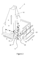
- the wing covers 4 are attached to rib feet 2a of the ribs 2 by an automated process using a computer numerical control (CNC) machine tool 5, shown in Figure 2 .
- CNC computer numerical control
- the machine tool 5 is a 5-axis machine tool configured for fully automated drilling and slave bolt insertion for assembling the wing covers 4 to the rib feet 2a.
- the machine tool is designed to produce holes for final fasteners to fasten the wing covers 4 to the ribs 2.
- the machine tool may perform additional operations, such as drilling off holes for engine pylon reinforcings, etc.
- the machine tool is in essence a travelling column post mill with a 5-axis machine head 6.
- the machine head is configured to provide a gap closing pressure, e.g. to press the wing cover 4 onto the rib feet 2a, during machine processing, and also has the capability to bring one of a variety of process tools to the tool point for drilling and fastening operations.
- the machine tool 5 is mounted upon rails (not shown) for movement along the X-axis so that it is able to travel the full length of the wing assembly jig 1.
- the machine tool 5 includes a machine column 7 having rails 8 for vertical movement of the machine head 6 along the Y-axis.
- Mounted to the Y-axis rails 8 is a Y-axis sled 9 having a rotary table bearing having an axis parallel to X and providing a rotation in A to accommodate cord-wise curvature of the wing cover 4.
- a similar arrangement provides for rotation in the B-axis, around an axis parallel to Y.
- the machine head 6 sits below the A-B pivot and includes a plurality of interchangeable process tools on a shuttle table.
- the machine head has a thrust axis U, which is parallel to the z-axis when A is zero. Movement along all axes is servo-controlled.
- the machine head includes a pressure foot 10 and a through-skin sensor (TSS) 11.
- TSS 11 is called automatically by the CNC machine tool 5.
- the TSS 11 forms part of a position sensor system and allows an operator to locally re-zero the machine tool as desired.
- the TSS 11 may also form part of a measurement system for measuring the profile of a workpiece feature.
- the process tools of the machine head 6 may include a drill spindle, a slave bolt detection tool, a hole diameter probe, a bolt insertion tool, or any of a variety of process tools, as required.
- the machine tool 5 includes an operator platform 12 with an interface console 13.
- Figure 3 shows a partial view of one of the wing covers 4 having a predrilled blind locating hole 14 formed in its inner surface 15, this being opposite its outer surface 16 which will form the outer aerodynamic surface of the completed aircraft wing.
- Figure 4 shows the wing cover 4 having the blind locating hole 14 when installed in the jig 1 (not visible in Figure 4 ) adjacent a rib foot 2a and with the machine head 6 in close proximity such that the TSS 11 is approximately aligned in the X and Y directions with the position of the blind locating hole 14.
- the TSS 11 includes an ultrasonic probe 17 which emits an ultrasonic wave towards the wing cover 4 from the side nearest the outer surface 16 of the wing cover 4.
- the ultrasonic wave travels through the thickness of the wing cover 4 and reflects back a reflected ultrasonic wave that is distorted by the blind locating hole 14 due to the differing material thickness of the wing cover at the location of the blind locating hole 14 as compared with the surrounding material thickness.
- the reflected ultrasonic wave is received at the ultrasonic probe 17.
- the output from the TSS 11 is coupled to a controller of the machine tool position sensor system which analyses the reflected ultrasonic wave to compute the precise location of the blind locating hole 14 in the X-Y-Z coordinate system by closed loop control.
- the position sensor system uses the TSS 11 to measure the material thickness of the wing cover by scanning along the X and Y axes so as to determine a geometric centre of the blind locating hole 14. Since the blind locating hole 14 is predrilled in the wing cover 4 prior to assembly in the jig 1 the machine tool 5 can be precisely locally re-zeroed off the blind locating hole 14.
- the machine tool 6 having been locally re-zeroed, is aligned such that one of the process tools, in this case the drill spindle 18, is precisely aligned with the desired fastener hole location for fastening the wing cover 4 to the rib foot 2a.
- the machine head 6 is advanced such that the pressure foot 10 contacts the outer surface 16 of the wing cover 4 to apply a gap closing pressure to the wing cover 4. This causes the inner surface 15 of the wing cover 4 to bear against the rib foot 2a.
- the drill spindle 18 is then advanced along U to drill a hole through the wing cover 4 and the rib foot 2a.
- FIG. 7 Following retraction of the drill spindle 18 and the machine head 6 the completed through-hole 19 is shown in Figure 7 .
- One or more further processes may be performed by the machine tool, such as countersinking, deburring, etc., before a final fastener 20 is installed to fasten the wing cover 4 to the rib foot 2a, as shown in Figure 8 .
- the deburring may be performed manually after the cover 4 has been removed and prior to fastener installation.
- the machine tool may also use the TSS 11 to measure exit delamination of the hole drilled by the drill spindle 18 where the rib foot 2a, the cover 4, or other workpiece component(s), are laminate components, e.g. comprising fibre reinforced composite.
- the machine tool may position the TSS 11 adjacent the drilled hole 19, measure the profile of the drilled hole, and output a measurement of the extent of any exit delamination around the periphery of the hole. Further processing, by the machine tool 5 or manually, may be performed to address any excessive exit delamination prior to installation of the final fasteners.
- the position sensor system may use the TSS 11 to pick up the edge profile of the rib foot 2a, or other workpiece feature. This may obviate any need for the pre-drilled blind holes.
- the machine tool 5 may use the TSS 11 to scan in orthogonal directions, or may scan in one direction only, or may scan in multiple directions.
- the position sensor system may use the TSS 11 to locate the centre of a thinnest part of the workpiece, or a workpiece feature edge.
Abstract
A computer numerical control machine tool with a machine head having one or more process tools. The machine head is moveable with respect to a workpiece. A position sensor system detects the position of the machine head relative to the workpiece. A controller coupled to the position sensor system provides closed loop control of the position of the machine head relative to the workpiece. The position sensor system includes an ultrasonic probe. Also a method of controlling the position of a computer numerical control machine tool.
Description
- The present invention relates to a control and measurement system for a machine tool such as a computer numerical control machine tool, and a method therefor.
- Computer numerical control (CNC) machine tools are used widely in manufacturing industries to perform automated production tasks. CNC machine tools typical have a machine head which can carry process tools for a variety of processes, such as drilling, cutting etc. and these process tools may be interchangeable. Once a workpiece is installed the CNC machine tool can be programmed to perform a series of steps on the workpiece to produce a part in a highly automated process with great accuracy.
- In the aircraft manufacturing industry it is known to use a CNC machine tool in the manufacture of an aircraft wing. A typical aircraft wing construction includes joining wing covers (or skins) to longitudinal spars and transverse ribs. The covers may have longitudinal stiffeners (known as stringers) attached or integrally formed therewith prior to assembly with the ribs and spars to form a "wing box".
- In the process of assembling the wing box all of the ribs and spars needed to form the complete wing box are typically arranged in a jig to ensure dimensional accuracy. The covers are then offered up to the ribs and spars in the jig and then drilled before final fasteners are installed to fix the covers to the ribs and spars. To avoid unwanted pre-stresses and to ensure that the completed wing box conforms to the design shape the covers, ribs and spars are not pre-drilled prior to assembly. Also, the cover must be drilled from the side that will form the aerodynamic surface due to machine tool accessibility constraints and, in the case the cover comprises laminate composite materials, to ensure that any drill hole exit delamination is not on the outer aerodynamic surface.
- Thermal expansion and manufacturing tolerances make it difficult to locate the CNC machine tool for performing the drilling operations to align with the rib feet and spar flanges hidden behind the cover. The rib feet particularly may have only a small land around the intended fastener hole location so accurate fastener positioning is crucial.
- A CNC machine tool in current use for wing box assembly uses a magnetic field sensor to align the machine tool with magnets manually installed in blind holes formed at the desired fastener locations on the inner surface of the wing cover, i.e. the side opposite the outer surface that will form the aerodynamic surface. This solution provides the required positioning accuracy but has a drawback in that the installation and subsequent removal of very many magnets on the wing cover makes use of the CNC machine tool a two-man operation.
- The present invention aims to solve this problem to facilitate one-man operation of the machine tool.
- The invention relates to a computer numerical control machine tool comprising a machine head having one or more process tools and moveable with respect to a workpiece, and an ultrasonic probe. The ultrasonic probe may be used to measure material thickness of the workpiece for positioning the machine head relative to the workpiece and/or for measuring exit delamination of a hole formed by the machine tool.
- A first aspect of the invention provides a computer numerical control machine tool comprising a machine head having one or more process tools and moveable with respect to a workpiece, a position sensor system for detecting the position of the machine head relative to the workpiece, and a controller coupled to the position sensor system for closed loop control of the position of the machine head relative to the workpiece, wherein the position sensor system includes an ultrasonic probe.
- A further aspect of the invention provides a method of controlling the position of a computer numerical control machine tool, the machine tool comprising a machine head having one or more process tools and moveable with respect to a workpiece, a position sensor system including an ultrasonic probe, and a controller coupled to the position sensor, and the method comprises detecting the position of the machine head relative to the workpiece with the position sensor system, and closed loop control of the position of the machine head relative to the workpiece with the controller.
- The invention is advantageous in that the ultrasonic position sensor system can detect the location of a feature of the workpiece on a side of the workpiece opposite to that where the machine tool is located but without requiring positioning devices, such as magnets or machine readable sensors, to be installed by a second operator. In this way the machine tool facilitates single operator operations. The absence of positioning magnets such as those currently used in the art may enable machine processing of materials such as Titanium which are known to distort the magnetic field of such magnets and until now have required alternative processing techniques.
- The position sensor system may be configured to use the ultrasonic probe for measuring material thickness of the workpiece.
- The position sensor system may be configured to measure the material thickness in the vicinity of a predetermined location on the workpiece.
- The position sensor system may be configured to measure the material thickness of the workpiece by scanning along at least one axis.
- The scan may be performed along two orthogonal axes.
- The position sensor system may be configured to determine a geometric centre of a workpiece feature having a material thickness different to that of the workpiece feature environs. For example, the position sensor system may be used to determine the centre of a blind hole formed in the workpiece. Alternatively the position sensor may be used to determine the centre of a land around an intended fastener location.
- The position sensor system may be configured to determine the material thickness profile of a workpiece feature. For example, where the workpiece feature is a blind hole the material thickness at the blind hole will be reduced compared to the surrounding material thickness.
- The machine tool may be operable to automatically perform a process machining operation on the workpiece once the machine head has been automatically aligned with workpiece using the position sensor system.
- The machine tool may be a multi-axis machine tool for fully automated drilling of holes for final fasteners in aircraft wing box components in an aircraft wing box assembly jig.
- Embodiments of the invention will now be described with reference to the accompanying drawings, in which:
-
Figure 1 shows a schematic view of an aircraft wing box jig with ribs and spars installed, ready to receive the wing covers; -
Figure 2 shows a CNC machine tool for automated drilling and countersinking holes for fasteners to attach the covers to the ribs and spars in the jig; -
Figure 3 shows a partial view of the wing cover having a blind locating hole formed in its inner surface; -
Figure 4 shows a partial detail view of the wing cover when installed in the jig adjacent a rib foot and the CNC machine tool, with the position sensor system of the machine tool proximate the blind locating hole; -
Figure 5 shows a partial detail view of the wing cover, the rib foot and the CNC machine tool, with the machine head aligned for a drilling process; -
Figure 6 shows a partial detail view of the wing cover, the rib foot and the CNC machine tool, with the machine head advanced during the drilling process; -
Figure 7 shows a partial detail view of the wing cover, the rib foot and the CNC machine tool, with the machine head retracted following the drilling process; and -
Figure 8 shows a partial detail view of the wing cover fastened to the rib foot. -
Figure 1 shows a side view of an aircraftwing box jig 1 with a plurality of ribs 2 (only one of which is visible inFigure 1 ) coupled to front andrear spars 3 installed in thejig 1 and ready to receivewing covers 4. Thewing covers 4 are attached torib feet 2a of theribs 2 by an automated process using a computer numerical control (CNC)machine tool 5, shown inFigure 2 . - The
machine tool 5 is a 5-axis machine tool configured for fully automated drilling and slave bolt insertion for assembling the wing covers 4 to therib feet 2a. The machine tool is designed to produce holes for final fasteners to fasten the wing covers 4 to theribs 2. The machine tool may perform additional operations, such as drilling off holes for engine pylon reinforcings, etc. The machine tool is in essence a travelling column post mill with a 5-axis machine head 6. The machine head is configured to provide a gap closing pressure, e.g. to press thewing cover 4 onto therib feet 2a, during machine processing, and also has the capability to bring one of a variety of process tools to the tool point for drilling and fastening operations. - The
machine tool 5 is mounted upon rails (not shown) for movement along the X-axis so that it is able to travel the full length of thewing assembly jig 1. Themachine tool 5 includes amachine column 7 havingrails 8 for vertical movement of themachine head 6 along the Y-axis. Mounted to the Y-axis rails 8 is a Y-axis sled 9 having a rotary table bearing having an axis parallel to X and providing a rotation in A to accommodate cord-wise curvature of thewing cover 4. A similar arrangement provides for rotation in the B-axis, around an axis parallel to Y. Themachine head 6 sits below the A-B pivot and includes a plurality of interchangeable process tools on a shuttle table. The machine head has a thrust axis U, which is parallel to the z-axis when A is zero. Movement along all axes is servo-controlled. - The machine head includes a
pressure foot 10 and a through-skin sensor (TSS) 11. The TSS 11 is called automatically by theCNC machine tool 5. TheTSS 11 forms part of a position sensor system and allows an operator to locally re-zero the machine tool as desired. TheTSS 11 may also form part of a measurement system for measuring the profile of a workpiece feature. The process tools of themachine head 6 may include a drill spindle, a slave bolt detection tool, a hole diameter probe, a bolt insertion tool, or any of a variety of process tools, as required. Finally, themachine tool 5 includes anoperator platform 12 with aninterface console 13. -
Figure 3 shows a partial view of one of the wing covers 4 having a predrilledblind locating hole 14 formed in itsinner surface 15, this being opposite itsouter surface 16 which will form the outer aerodynamic surface of the completed aircraft wing.Figure 4 shows thewing cover 4 having theblind locating hole 14 when installed in the jig 1 (not visible inFigure 4 ) adjacent arib foot 2a and with themachine head 6 in close proximity such that theTSS 11 is approximately aligned in the X and Y directions with the position of theblind locating hole 14. - The
TSS 11 includes anultrasonic probe 17 which emits an ultrasonic wave towards thewing cover 4 from the side nearest theouter surface 16 of thewing cover 4. The ultrasonic wave travels through the thickness of thewing cover 4 and reflects back a reflected ultrasonic wave that is distorted by theblind locating hole 14 due to the differing material thickness of the wing cover at the location of theblind locating hole 14 as compared with the surrounding material thickness. The reflected ultrasonic wave is received at theultrasonic probe 17. - The output from the
TSS 11 is coupled to a controller of the machine tool position sensor system which analyses the reflected ultrasonic wave to compute the precise location of theblind locating hole 14 in the X-Y-Z coordinate system by closed loop control. In the preferred embodiment the position sensor system uses theTSS 11 to measure the material thickness of the wing cover by scanning along the X and Y axes so as to determine a geometric centre of theblind locating hole 14. Since theblind locating hole 14 is predrilled in thewing cover 4 prior to assembly in thejig 1 themachine tool 5 can be precisely locally re-zeroed off theblind locating hole 14. - Turning next to
Figure 5 themachine tool 6, having been locally re-zeroed, is aligned such that one of the process tools, in this case thedrill spindle 18, is precisely aligned with the desired fastener hole location for fastening thewing cover 4 to therib foot 2a. As shown inFigure 6 themachine head 6 is advanced such that thepressure foot 10 contacts theouter surface 16 of thewing cover 4 to apply a gap closing pressure to thewing cover 4. This causes theinner surface 15 of thewing cover 4 to bear against therib foot 2a. Thedrill spindle 18 is then advanced along U to drill a hole through thewing cover 4 and therib foot 2a. - Following retraction of the
drill spindle 18 and themachine head 6 the completed through-hole 19 is shown inFigure 7 . One or more further processes may be performed by the machine tool, such as countersinking, deburring, etc., before afinal fastener 20 is installed to fasten thewing cover 4 to therib foot 2a, as shown inFigure 8 . The deburring may be performed manually after thecover 4 has been removed and prior to fastener installation. - The machine tool may also use the
TSS 11 to measure exit delamination of the hole drilled by thedrill spindle 18 where therib foot 2a, thecover 4, or other workpiece component(s), are laminate components, e.g. comprising fibre reinforced composite. The machine tool may position theTSS 11 adjacent the drilledhole 19, measure the profile of the drilled hole, and output a measurement of the extent of any exit delamination around the periphery of the hole. Further processing, by themachine tool 5 or manually, may be performed to address any excessive exit delamination prior to installation of the final fasteners. - As an alternative to picking up the location of the pre-drilled blind hole, the position sensor system may use the
TSS 11 to pick up the edge profile of therib foot 2a, or other workpiece feature. This may obviate any need for the pre-drilled blind holes. - The
machine tool 5 may use theTSS 11 to scan in orthogonal directions, or may scan in one direction only, or may scan in multiple directions. The position sensor system may use theTSS 11 to locate the centre of a thinnest part of the workpiece, or a workpiece feature edge. - Although the invention has been described above with reference to one or more preferred embodiments, it will be appreciated that various changes or modifications may be made without departing from the scope of the invention as defined in the appended claims.
Claims (15)
- A computer numerical control machine tool comprising a machine head having one or more process tools and moveable with respect to a workpiece, a position sensor system for detecting the position of the machine head relative to the workpiece, and a controller coupled to the position sensor system for closed loop control of the position of the machine head relative to the workpiece, wherein the position sensor system includes an ultrasonic probe.
- A machine tool according to claim 1, wherein the position sensor system is configured to use the ultrasonic probe for measuring material thickness of the workpiece.
- A machine tool according to claim 2, wherein the position sensor system is configured to measure the material thickness in the vicinity of a predetermined location on the workpiece.
- A machine tool according to claim 2 or claim 3, wherein the position sensor system is configured to measure the material thickness of the workpiece by scanning along at least one axis, preferably wherein the scan is performed along two orthogonal axes.
- A machine tool according to any of claims 2 to 4, wherein the position sensor system is configured to determine a geometric centre of a workpiece feature having a material thickness different to that of the workpiece feature environs.
- A machine tool according to any of claims 2 to 4, wherein the position sensor system is configured to determine the material thickness profile of a workpiece feature.
- A machine tool according to any preceding claim, wherein the machine tool is operable to automatically perform a process machining operation on the workpiece once the machine head has been automatically aligned with workpiece using the position sensor system.
- A machine tool according to any preceding claim, wherein the machine tool is a multi-axis machine tool for fully automated drilling of holes for final fasteners in aircraft wing box components in an aircraft wing box assembly jig.
- A method of controlling the position of a computer numerical control machine tool, the machine tool comprising a machine head having one or more process tools and moveable with respect to a workpiece, a position sensor system including an ultrasonic probe, and a controller coupled to the position sensor, and the method comprises detecting the position of the machine head relative to the workpiece with the position sensor system, and closed loop control of the position of the machine head relative to the workpiece with the controller.
- A method according to claim 9, further comprising measuring material thickness of the workpiece using the ultrasonic probe, preferably wherein the material thickness measuring step includes measuring the material thickness in the vicinity of a predetermined location on the workpiece, and preferably wherein the material thickness measuring step is performed by scanning along at least one axis of the machine tool, and further preferably wherein the scan is performed along two orthogonal axes of the machine tool.
- A method according to claim 10, further comprising determining a geometric centre of a workpiece feature having a material thickness different to that of the workpiece feature environs using the position sensor system.
- A method according to claim 10 or claim 11, further comprising determining the material thickness profile of a workpiece feature using the position sensor system.
- A method according to any of claims 10 to 12, further comprising automatically performing a process machining operation on the workpiece once the machine head has been automatically aligned with workpiece using the position sensor system.
- A method according to claim 13, further comprising using the machine tool for fully automated drilling of holes for final fasteners in aircraft wing box components in an aircraft wing box assembly jig.
- A computer numerical control machine tool comprising a machine head having one or more process tools and moveable with respect to a workpiece, and an ultrasonic probe.
Applications Claiming Priority (1)
| Application Number | Priority Date | Filing Date | Title |
|---|---|---|---|
| GB1512297.1A GB2540374A (en) | 2015-07-14 | 2015-07-14 | Machine tool control & measurement system |
Publications (1)
| Publication Number | Publication Date |
|---|---|
| EP3118698A1 true EP3118698A1 (en) | 2017-01-18 |
Family
ID=54013924
Family Applications (1)
| Application Number | Title | Priority Date | Filing Date |
|---|---|---|---|
| EP16178305.5A Withdrawn EP3118698A1 (en) | 2015-07-14 | 2016-07-07 | Machine tool control & measurement system |
Country Status (4)
| Country | Link |
|---|---|
| US (1) | US20170016718A1 (en) |
| EP (1) | EP3118698A1 (en) |
| CN (1) | CN106354090A (en) |
| GB (1) | GB2540374A (en) |
Cited By (1)
| Publication number | Priority date | Publication date | Assignee | Title |
|---|---|---|---|---|
| CN106843152A (en) * | 2017-03-06 | 2017-06-13 | 航天材料及工艺研究所 | A kind of Bresse normal circle hole numerical-control processing method based on five-axis machine tool on-line measurement |
Families Citing this family (4)
| Publication number | Priority date | Publication date | Assignee | Title |
|---|---|---|---|---|
| CN106863486A (en) * | 2017-02-07 | 2017-06-20 | 广州纬纶信息科技有限公司 | A kind of single gantry two-shipper head drilling equipment control method |
| CN108406338B (en) * | 2018-03-20 | 2023-08-11 | 吉林大学 | Multi-dimensional ultrasonic tool system and method with tool head action space being quadric surface |
| EP4016210A1 (en) * | 2020-12-17 | 2022-06-22 | Airbus Operations GmbH | Positioning-, drilling-, and joining methods for a machine tool device |
| CN114161229B (en) * | 2021-12-14 | 2022-10-04 | 电子科技大学 | Device and method for machining rotary structure for electric slit |
Citations (4)
| Publication number | Priority date | Publication date | Assignee | Title |
|---|---|---|---|---|
| US4281385A (en) * | 1978-07-06 | 1981-07-28 | Toyoda-Koki Kabushiki Kaisha | Control system for a machine tool |
| DE102005040180A1 (en) * | 2005-06-09 | 2006-12-14 | Rheinisch-Westfälisch Technische Hochschule Aachen | Ultrasonic measuring system for machine tools |
| US20080260482A1 (en) * | 2005-10-21 | 2008-10-23 | Volvo Aero Corporation | Method and Device for Controlling a Tool with Ultrasonic Waves |
| US20130195573A1 (en) * | 2010-10-14 | 2013-08-01 | Christian Podiebrad | Machine tool comprising an ultrasonic sensor |
Family Cites Families (1)
| Publication number | Priority date | Publication date | Assignee | Title |
|---|---|---|---|---|
| JP2001260021A (en) * | 2000-03-16 | 2001-09-25 | Toshiba Mach Co Ltd | Numerical control system for roll grinding machine |
-
2015
- 2015-07-14 GB GB1512297.1A patent/GB2540374A/en not_active Withdrawn
-
2016
- 2016-07-07 EP EP16178305.5A patent/EP3118698A1/en not_active Withdrawn
- 2016-07-12 CN CN201610546622.3A patent/CN106354090A/en active Pending
- 2016-07-13 US US15/209,170 patent/US20170016718A1/en not_active Abandoned
Patent Citations (4)
| Publication number | Priority date | Publication date | Assignee | Title |
|---|---|---|---|---|
| US4281385A (en) * | 1978-07-06 | 1981-07-28 | Toyoda-Koki Kabushiki Kaisha | Control system for a machine tool |
| DE102005040180A1 (en) * | 2005-06-09 | 2006-12-14 | Rheinisch-Westfälisch Technische Hochschule Aachen | Ultrasonic measuring system for machine tools |
| US20080260482A1 (en) * | 2005-10-21 | 2008-10-23 | Volvo Aero Corporation | Method and Device for Controlling a Tool with Ultrasonic Waves |
| US20130195573A1 (en) * | 2010-10-14 | 2013-08-01 | Christian Podiebrad | Machine tool comprising an ultrasonic sensor |
Cited By (2)
| Publication number | Priority date | Publication date | Assignee | Title |
|---|---|---|---|---|
| CN106843152A (en) * | 2017-03-06 | 2017-06-13 | 航天材料及工艺研究所 | A kind of Bresse normal circle hole numerical-control processing method based on five-axis machine tool on-line measurement |
| CN106843152B (en) * | 2017-03-06 | 2019-03-22 | 航天材料及工艺研究所 | A kind of Bresse normal circle hole numerical-control processing method based on five-axis machine tool on-line measurement |
Also Published As
| Publication number | Publication date |
|---|---|
| GB201512297D0 (en) | 2015-08-19 |
| GB2540374A (en) | 2017-01-18 |
| CN106354090A (en) | 2017-01-25 |
| US20170016718A1 (en) | 2017-01-19 |
Similar Documents
| Publication | Publication Date | Title |
|---|---|---|
| EP3118698A1 (en) | Machine tool control & measurement system | |
| Tian et al. | Auto-normalization algorithm for robotic precision drilling system in aircraft component assembly | |
| US7128506B2 (en) | Toolhead for multi-axis machine tools | |
| US20090228134A1 (en) | Determinant Wing Assembly | |
| CN108015312A (en) | For robot high accuracy drilling and the end effector and measuring method of counter boring | |
| Eguti et al. | Design of a robotic orbital driller for assembling aircraft structures | |
| EP2881817B1 (en) | System and method for operating a machine and performing quality assurance | |
| AU2015249042B2 (en) | Systems and methods for coordinate transformation using non-destructive imaging | |
| JP2000506816A (en) | Definitive wing assembly | |
| US11401050B2 (en) | Method and apparatus for assembling aircraft airframes | |
| Liu et al. | A helical milling and oval countersinking end-effector for aircraft assembly | |
| Shi et al. | New design of a compact aero-robotic drilling end effector: An experimental analysis | |
| US9751136B2 (en) | Back spotfacing system and method | |
| Zhang et al. | Design of drilling and riveting multi-functional end effector for CFRP and aluminum components in robotic aircraft assembly | |
| Mir et al. | 777X control surface assembly using advanced robotic automation | |
| EP3587242A1 (en) | Method and apparatus for assembling aircraft airframes | |
| EP3587251A1 (en) | Method and apparatus for producing shims | |
| Xiao et al. | Research on automatic assembly technology for final assembly of helicopter fuselage | |
| US11970289B2 (en) | Method and apparatus for producing shims | |
| US20060010689A1 (en) | Automated drill process for two-diameter holes in multi-layer variable thickness composite materials | |
| JP4014939B2 (en) | Tool mounting position measuring device | |
| EP3588219A1 (en) | Method and apparatus for producing component parts of aircraft airframes | |
| EP3587279A1 (en) | Method and apparatus for producing shims for use in an aircraft airframe | |
| McKenzie et al. | Drill Gantry Cell for New F5 Wing Production |
Legal Events
| Date | Code | Title | Description |
|---|---|---|---|
| PUAI | Public reference made under article 153(3) epc to a published international application that has entered the european phase |
Free format text: ORIGINAL CODE: 0009012 |
|
| STAA | Information on the status of an ep patent application or granted ep patent |
Free format text: STATUS: THE APPLICATION HAS BEEN PUBLISHED |
|
| AK | Designated contracting states |
Kind code of ref document: A1 Designated state(s): AL AT BE BG CH CY CZ DE DK EE ES FI FR GB GR HR HU IE IS IT LI LT LU LV MC MK MT NL NO PL PT RO RS SE SI SK SM TR |
|
| AX | Request for extension of the european patent |
Extension state: BA ME |
|
| STAA | Information on the status of an ep patent application or granted ep patent |
Free format text: STATUS: THE APPLICATION IS DEEMED TO BE WITHDRAWN |
|
| 18D | Application deemed to be withdrawn |
Effective date: 20170719 |