EP3118629A1 - Dispensing device and dispensing method - Google Patents
Dispensing device and dispensing method Download PDFInfo
- Publication number
- EP3118629A1 EP3118629A1 EP15761890.1A EP15761890A EP3118629A1 EP 3118629 A1 EP3118629 A1 EP 3118629A1 EP 15761890 A EP15761890 A EP 15761890A EP 3118629 A1 EP3118629 A1 EP 3118629A1
- Authority
- EP
- European Patent Office
- Prior art keywords
- probe
- container
- amount
- pressure
- dispensing
- Prior art date
- Legal status (The legal status is an assumption and is not a legal conclusion. Google has not performed a legal analysis and makes no representation as to the accuracy of the status listed.)
- Granted
Links
Images


Classifications
-
- G—PHYSICS
- G01—MEASURING; TESTING
- G01N—INVESTIGATING OR ANALYSING MATERIALS BY DETERMINING THEIR CHEMICAL OR PHYSICAL PROPERTIES
- G01N35/00—Automatic analysis not limited to methods or materials provided for in any single one of groups G01N1/00 - G01N33/00; Handling materials therefor
- G01N35/10—Devices for transferring samples or any liquids to, in, or from, the analysis apparatus, e.g. suction devices, injection devices
- G01N35/1009—Characterised by arrangements for controlling the aspiration or dispense of liquids
- G01N35/1016—Control of the volume dispensed or introduced
-
- B—PERFORMING OPERATIONS; TRANSPORTING
- B01—PHYSICAL OR CHEMICAL PROCESSES OR APPARATUS IN GENERAL
- B01L—CHEMICAL OR PHYSICAL LABORATORY APPARATUS FOR GENERAL USE
- B01L3/00—Containers or dishes for laboratory use, e.g. laboratory glassware; Droppers
- B01L3/02—Burettes; Pipettes
- B01L3/021—Pipettes, i.e. with only one conduit for withdrawing and redistributing liquids
-
- B—PERFORMING OPERATIONS; TRANSPORTING
- B01—PHYSICAL OR CHEMICAL PROCESSES OR APPARATUS IN GENERAL
- B01L—CHEMICAL OR PHYSICAL LABORATORY APPARATUS FOR GENERAL USE
- B01L3/00—Containers or dishes for laboratory use, e.g. laboratory glassware; Droppers
- B01L3/52—Containers specially adapted for storing or dispensing a reagent
-
- G—PHYSICS
- G01—MEASURING; TESTING
- G01F—MEASURING VOLUME, VOLUME FLOW, MASS FLOW OR LIQUID LEVEL; METERING BY VOLUME
- G01F22/00—Methods or apparatus for measuring volume of fluids or fluent solid material, not otherwise provided for
- G01F22/02—Methods or apparatus for measuring volume of fluids or fluent solid material, not otherwise provided for involving measurement of pressure
-
- G—PHYSICS
- G01—MEASURING; TESTING
- G01N—INVESTIGATING OR ANALYSING MATERIALS BY DETERMINING THEIR CHEMICAL OR PHYSICAL PROPERTIES
- G01N35/00—Automatic analysis not limited to methods or materials provided for in any single one of groups G01N1/00 - G01N33/00; Handling materials therefor
- G01N35/10—Devices for transferring samples or any liquids to, in, or from, the analysis apparatus, e.g. suction devices, injection devices
- G01N35/1079—Devices for transferring samples or any liquids to, in, or from, the analysis apparatus, e.g. suction devices, injection devices with means for piercing stoppers or septums
-
- B—PERFORMING OPERATIONS; TRANSPORTING
- B01—PHYSICAL OR CHEMICAL PROCESSES OR APPARATUS IN GENERAL
- B01L—CHEMICAL OR PHYSICAL LABORATORY APPARATUS FOR GENERAL USE
- B01L2200/00—Solutions for specific problems relating to chemical or physical laboratory apparatus
- B01L2200/06—Fluid handling related problems
- B01L2200/0673—Handling of plugs of fluid surrounded by immiscible fluid
-
- B—PERFORMING OPERATIONS; TRANSPORTING
- B01—PHYSICAL OR CHEMICAL PROCESSES OR APPARATUS IN GENERAL
- B01L—CHEMICAL OR PHYSICAL LABORATORY APPARATUS FOR GENERAL USE
- B01L2200/00—Solutions for specific problems relating to chemical or physical laboratory apparatus
- B01L2200/14—Process control and prevention of errors
- B01L2200/143—Quality control, feedback systems
-
- B—PERFORMING OPERATIONS; TRANSPORTING
- B01—PHYSICAL OR CHEMICAL PROCESSES OR APPARATUS IN GENERAL
- B01L—CHEMICAL OR PHYSICAL LABORATORY APPARATUS FOR GENERAL USE
- B01L2200/00—Solutions for specific problems relating to chemical or physical laboratory apparatus
- B01L2200/14—Process control and prevention of errors
- B01L2200/143—Quality control, feedback systems
- B01L2200/146—Employing pressure sensors
-
- B—PERFORMING OPERATIONS; TRANSPORTING
- B01—PHYSICAL OR CHEMICAL PROCESSES OR APPARATUS IN GENERAL
- B01L—CHEMICAL OR PHYSICAL LABORATORY APPARATUS FOR GENERAL USE
- B01L2400/00—Moving or stopping fluids
- B01L2400/04—Moving fluids with specific forces or mechanical means
- B01L2400/0475—Moving fluids with specific forces or mechanical means specific mechanical means and fluid pressure
- B01L2400/0487—Moving fluids with specific forces or mechanical means specific mechanical means and fluid pressure fluid pressure, pneumatics
Definitions
- the present invention relates to a liquid dispensing device, an automatic analysis device equipped with the same, and a liquid dispensing method, such as a dispensing method for collecting liquid from a liquid holding container, such as a sample container or a reagent container, and dispensing the liquid into a reaction container.
- a liquid dispensing method such as a dispensing method for collecting liquid from a liquid holding container, such as a sample container or a reagent container, and dispensing the liquid into a reaction container.
- automatic analysis devices generally employ an non-sealed liquid holding container with the upper opening portion opened.
- a rubber plug such as a vacuum blood collection tube
- dispensing devices too, there is a demand for direct liquid collection without having to unplug the sealed holding container.
- the inside of a sealed liquid holding container typically has a negative pressure relative to the external atmospheric pressure.
- the internal pressure may have become positive relative to the external atmospheric pressure.
- the flow passageway of the dispensing device as a whole connected to the probe may contract or expand due to a pressure variation, causing a movement of the liquid or gas in the flow passageway.
- the flow passageway may be deformed again by exposure to the atmosphere, causing a movement of the liquid or gas in the flow passageway, including a suctioned sample.
- the position of the suctioned sample in the probe may vary due to different internal pressures of the liquid holding container. This makes it impossible to obtain a constant amount of dispensed liquid relative to the amount of operation of a pump, and to achieve required dispensing accuracy.
- a probe is provided with a thin tube for liquid sample suction and a thin tube for ventilation that are integrated (see Patent Literature 1).
- the probe equipped with the two passageways is passed through the rubber plug, and ventilation is performed via the ventilation passageway while liquid is suctioned via the suction passageway, thus eliminating the pressure difference between the inside and outside of the liquid holding container.
- an insertion hole for the sample collection probe is formed in the sample container plug using a perforating device equipped with a Z-shaped blade (see Patent Literature 2). According to this technology, as the sample collection probe is inserted, the opening or hole formed in the plug expands, whereby sufficient ventilation is provided, eliminating the pressure difference between the inside and outside of the liquid holding container.
- Patent Literature 1 the ventilation passageway is provided in addition to the suction passageway.
- the probe outer shape is increased, with a resultant increase in the frictional force experienced when piercing the rubber plug. Accordingly, a large force is required for probe removal or insertion.
- Patent Literature 2 because the perforating blade is used in addition to the sample collection probe, the device becomes more complex and the time and effort for maintenance, for example, increases. Further, in order to avoid cross contamination of samples, the perforating blade needs to be washed, resulting in an increase in the consumption of washing water.
- the present invention was made in view of the above circumstances, and an object of the present invention is to provide a dispensing method that can increase the accuracy of dispensing liquid from a sealed liquid holding container without an increase in device complexity due to the provision of a ventilation opening.
- pressures inside and outside a sealed liquid holding container are measured, the amount of deformation of a dispensing flow passageway due to pressure variation is calculated, and the amount of operation of a pump is corrected in accordance with the amount of deformation.
- a dispensing device includes a pump; a probe connected to the pump via a piping; a pressure sensor that measures a pressure in the piping; and a control unit that controls the pump and the probe and that reads a signal from the pressure sensor.
- the control unit measures pressures outside and inside the container using the pressure sensor, and corrects the amount of operation of the pump in accordance with the measured pressures.
- the control unit may correct the amount of operation of the pump for discharging the liquid, or the amount of operation of the pump for suctioning or discharging air into or out of the probe.
- a dispensing method includes a step of suctioning a segmented air into a probe; a step of measuring a pressure outside a sealed container; a step of measuring a pressure inside the container; a step of calculating a correction amount for a discharge amount required for discharging a liquid suctioned by the probe from the container, based on the measured external and internal pressures; a step of suctioning into the probe the liquid held in the container; a step of removing the probe from the container; and a step of discharging the suctioned liquid from the probe by applying the correction amount for the discharge amount.
- a dispensing method includes a step of suctioning a segmented air into a probe; a step of measuring a pressure outside a sealed container; a step of inserting the probe into the container; a step of measuring a pressure inside the container; a step of discharging or suctioning the segmented air, based on the measured external and internal pressures, so that the amount of the segmented air becomes a predetermined amount with the probe removed from the container; a step of suctioning into the probe a liquid held in the container; a step of suctioning air from the container into a tip of the probe so that the air has a predetermined amount with the probe removed from the container; a step of removing the probe from the container; and a step of discharging the suctioned liquid from the probe.
- the accuracy of dispensing liquid from a sealed liquid holding container can be increased without an increase in device complexity due to the provision of a ventilation opening.
- An automatic analysis device is a device for automatically analyzing the components of a biological sample, such as blood or urine.
- the device includes a dispensing device for collecting and dispensing liquid from a sample container or a reagent container into a reaction container.
- FIG. 1 is a schematic diagram of an overall configuration example of the automatic analysis device.
- the automatic analysis device is provided with a sample rack 101 in which a plurality of sample containers 100 containing samples is disposed; a reagent disc 103 on which a plurality of reagent bottles 102 containing reagents is disposed; a cell disc 105 on which a plurality of reaction cells 104 for mixing sample and reagent into a reaction liquid is disposed; a sample dispensing mechanism 106 capable of moving a certain quantity of sample from within the sample containers 100 into the reaction cells 104; and a reagent dispensing mechanism 107 capable of moving a certain quantity of reagent from within the reagent bottles 102 into the reaction cells 104.
- the automatic analysis device is also provided with a stirring unit 108 for stirring and mixing the sample and reagent in the reaction cells 104; a measurement unit 109 for irradiating the reaction liquid in the reaction cells 104 with light and receiving resultant light; a washing unit 110 for washing the reaction cells 104; a computer 111 for controlling the driving of various parts of the analysis device, reading measurement data, and storing and analyzing data; an input device 112 capable of inputting necessary data into the computer 111 from the outside; and an output device 113 capable of displaying and outputting data to the outside.
- a stirring unit 108 for stirring and mixing the sample and reagent in the reaction cells 104
- a measurement unit 109 for irradiating the reaction liquid in the reaction cells 104 with light and receiving resultant light
- a washing unit 110 for washing the reaction cells 104
- a computer 111 for controlling the driving of various parts of the analysis device, reading measurement data, and storing and analyzing data
- an input device 112 capable of inputting necessary data into the computer
- An analysis of the amounts of components in a sample is performed by the following procedure. First, a certain quantity of a sample in the sample container 100 is dispensed into the reaction cell 104 by the sample dispensing mechanism 106. Then, a certain quantity of a reagent in the reagent bottle 102 is dispensed into the reaction cell 104 by the reagent dispensing mechanism 107. The sample and reagent in the reaction cell 104 are stirred by the stirring unit 108, producing a reaction liquid. If necessary, a plurality of reagents may be additionally dispensed into the reaction cell 104 by the reagent dispensing mechanism 107.
- the sample container 100, the reagent bottle 102, and the reaction cell 104 are moved to predetermined positions by the transport of the sample rack 101 and rotation of the reagent disc 103 and the cell disc 105. After completion of the reaction, the inside of the reaction cell 104 is washed by the washing mechanism 110 for the next analysis.
- the absorbance of the reaction liquid is measured by the measurement unit 109, and absorbance data are accumulated in the computer 111. From the accumulated absorbance data, the computer 111 analyzes the component amounts on the basis of calibration curve data and the Lambert-Beer law.
- the data necessary for controlling various units and analysis are input from the input device 112 into the computer 111. Various data and analysis results are displayed and output by the output device 113.
- FIG. 2 is a schematic diagram of a configuration example of the dispensing mechanism.
- an arm 115 On a shaft 114 that can be driven up and down, an arm 115 that can be rotationally driven is installed.
- a dispensing probe 116 At the end of the arm 115, a dispensing probe 116 is installed.
- the dispensing probe 116, a pressure sensor 117, and a syringe pump 118 are connected via piping 119.
- the dispensing flow passageway has the distal side thereof opened via the dispensing probe 116, with the proximal side thereof being configured to be opened and closed by an electromagnetic valve 120.
- the electromagnetic valve 120 is closed so as to suction or discharge the sample or reagent via the tip of the dispensing probe 116 by the movement of a plunger 121 installed in the syringe pump 118. After completion of the dispensing operation, the electromagnetic valve is opened to supply washing water from the proximal side.
- FIG. 3(a) illustrates a sealed sample container 100 immediately prior to the insertion of the dispensing probe 116 therein.
- the pressure inside the sample container 100 is the same as the pressure outside the sample container 100, i.e., the atmospheric pressure.
- the dispensing probe 116 is filled with water 122 for transmitting the pressure from the syringe pump 118.
- segmented air 123 is suctioned in advance, thus forming an air layer for preventing the sample 124, as it is being suctioned, from being mixed with and diluted by the water 122. Thereafter, as illustrated in FIG.
- the dispensing probe 116 is inserted into the sample container 100 via a rubber plug 125 until reaching inside the liquid of the sample 124. Then, as illustrated in FIG. 3(c) , the sample 124 is suctioned into the dispensing probe 116. As illustrated in FIG. 3(d) , the dispensing probe 116 is then removed out of the sample container 100. Finally, as illustrated in FIG. 3(e) , the dispensing probe 116 is moved into the reaction cell 104, and the suctioned sample 124 is discharged into the reaction cell 104, as illustrated in FIG. 3(f) .
- FIG. 4 a schematic diagram shown in FIG. 4 .
- FIG. 5 illustrating a temporal change in pressure in the dispensing flow passageway.
- the solid line indicates the case where the sample container has negative pressure
- the broken line indicates the case where the sample container has the atmospheric pressure.
- FIG. 4(a) illustrates the dispensing probe 116 filled with the water 122, with the segmented air 123 suctioned therein.
- the pressure in the dispensing flow passageway decreases during the suction operation, as illustrated in the pressure data of FIG. 5 between times t0 to t1.
- the dispensing probe 116 is inserted into the sample container 100 as illustrated in FIG. 4(b) , the dispensing flow passageway and the sample container 100 are hermetically connected.
- the inside of the reagent container 100 is at the atmospheric pressure, no change is caused in the pressure in the dispensing flow passageway, as illustrated in the pressure data of FIG. 5 between times t2 and t3.
- the pressure decreases from P0 to P1.
- the dispensing flow passageway contracts as a whole, and the interface of the water 122 in the dispensing probe 116 moves toward the sample container 100, whereby the volume of the segmented air 123 in the dispensing probe 116 decreases.
- the dispensing probe 116 reaches the sample 124 in the sample container 100, and the sample 124 is suctioned into the dispensing probe 116, as illustrated in FIG. 4(d) .
- the pressure in the dispensing flow passageway decreases during the suction operation, as illustrated in FIG. 5 between time t4 to t5.
- the dispensing probe 116 is removed out of the sample container 100, the hermetic connection of the dispensing flow passageway and the sample container 100 is released.
- the dispensing probe 116 is moved into the reaction cell 104, and the suctioned sample 124 is discharged into the reaction cell 105 as illustrated in FIG. 4(i).
- the discharge amount relative to the amount of operation of the pump becomes insufficient because of the entry of air into the tip.
- the amount of discharge operation is corrected in accordance with the pressure in the sealed sample container 100.
- a sequence of the present example will be described with reference to a flowchart shown in FIG. 6 and a schematic diagram shown in FIG. 7 .
- step 12 the atmospheric pressure is measured. This is performed at time t1 in FIG. 5 , whereby the atmospheric pressure P0 is obtained.
- step 13 the dispensing probe 116 is inserted via the rubber plug 125 into the air layer in the sealed sample container 100 ( FIG. 7(b) ).
- step 14 the pressure inside the sample container 100 is measured. This step is performed at time t3 in FIG. 5 , whereby pressure P1 is obtained.
- the atmospheric pressure P0 outside the sample container 100 and the internal pressure P1 having been acquired, a sample discharge correction amount is calculated in step 15. A method for calculating the correction amount will be described later.
- step 16 the dispensing probe 116 is lowered to the sample layer ( FIG. 7(c) ), and the sample 124 is suctioned in step 17 ( FIG. 7(d) ).
- step 18 as the dispensing probe 116 is removed from the sample container 100, the pressure in the dispensing flow passageway is opened to the atmospheric pressure, and air enters the tip of the dispensing probe 116, as illustrated in FIG. 7(f) .
- the dispensing probe 116 is inserted into the reaction cell 104 ( FIG. 7(g) ), and the sample 124 is discharged into the reaction cell 104 in step 19 by applying the sample discharge correction amount obtained in step 15 in consideration of the lack due to the entry of air ( FIG. 7(h) ), and the sequence ends.
- the measurement may be conducted between times t7 and t8 in which the dispensing probe 116 is removed from the sample container 100.
- the measurement may be conducted at both timings to obtain an average so as to effectively increase the pressure measurement accuracy.
- the pressure inside the sample container 100 may be measured between t5 and t6 rather than at time t3 in FIG. 5 , or at both timings.
- the pressure measurement may be conducted during the lowering as long as the measurement is not affected by vibrations and the like during operation. Further, if there is sufficient time for a pressure variation to become stabilized after the dispensing probe 116 is inserted into the sample container 100 and before reaching the sample layer, the dispensing probe 116 may not be stopped at the air layer but may be continuously lowered. The pressure measurement is also possible with the dispensing probe 116 immersed in the sample layer.
- the lack of discharge amount due to the pressure change corresponds to the amount of air V cor that has entered the tip of the dispensing probe 116 as illustrated in FIG. 7(f) , and is caused by deformation of the dispensing flow passageway and a volume change in the segmented air 123. Accordingly, the correction amount can be determined by calculating the relevant amounts of change.
- the dispensing flow passageway includes the dispensing probe 116, the pressure sensor 117, the syringe pump 118, and the piping 119 connecting them.
- the piping 119 is cylindrical and has an inner diameter r in , an outer diameter r out , a length 1, a Young's modulus E, and a Poisson's ratio v.
- the amount of deformation ⁇ V fc of the flow passageway as a whole is determined. Then, a change in volume of the segmented air 123 is determined.
- the suctioned amount of the segmented air 123 is Vair
- the amount of deformation ⁇ V fc of the piping when the dispensing probe 116 is inserted into the sample container 100 corresponds to the amount of leakage of the segmented air 123
- V cor ⁇ ⁇ V fc + ⁇ V air
- V dspc V dsp + V cor
- the amount of the segmented air 123 varies depending on the pressure inside the sealed sample container 100.
- the segmented air 123 serves to prevent the sample from being diluted by the entry of the water 122, which transmits the pressure from the syringe pump, into the suctioned sample.
- dilution may not be completely avoided, and the way the sample is diluted may differ depending on the amount of the segmented air.
- the segmented air 123 may expand or contract, and the time between the end of suctioning and pressure stabilization may be greatly influenced by the expansion or contraction, depending on the viscosity of the sample. For any of these problems, it is effective to perform correction so that the amount of the segmented air 123 becomes constant regardless of the pressure inside the sample container 100.
- the segmented air 123 is suctioned in step 21 ( FIG. 9(a) ). At this time, a greater amount of segmented air 123 than will eventually be held in the dispensing probe 116 is suctioned to allow for the adjustment by the correction operation. Then, in step 22, the atmospheric pressure is measured. This is performed at time t1 in FIG. 5 , whereby the atmospheric pressure P0 is obtained. In step 23, the dispensing probe 116 is inserted via the rubber plug 125 into the air layer of the sealed sample container 100 ( FIG. 9(b) ), and the pressure inside the sample container 100 is measured in step 24. This step is performed at time t3 in FIG. 5 , whereby pressure P1 is obtained.
- step 25 The atmospheric pressure P0 outside the sample container 100 and the internal pressure P1 having been acquired, air discharge and air suction correction amounts are calculated in step 25. A method for calculating the correction amounts will be described later.
- step 26 an air discharge operation is performed by applying the result of the correction amount calculation in step 25 so as to achieve a constant amount of the segmented air 123 ( FIG. 9(c) ).
- step 27 the dispensing probe 116 is lowered to the sample layer ( FIG. 9(d) ), and the sample 124 is suctioned in step 28 ( FIG. 9(e) ).
- step 29 the dispensing probe 116 up to the air layer in step 29 ( FIG. 9(f) ), and an air suction operation is performed in step 30 by applying the result of the correction amount calculation in step 25 in consideration of the amount of air that enters the tip when the pressure in the dispensing flow passageway returns to the atmospheric pressure ( FIG. 9(g) ).
- step 31 FIG.
- the internal pressure of the dispensing flow passageway is opened to the atmospheric pressure, allowing air to enter the tip of the dispensing probe 116, as described above. If the inside of the sample container 100 is at positive pressure, as the positive pressure is opened to the atmospheric pressure, the dispensing flow passageway will contract and the sample 124 may leak from the dispensing probe 116. However, when the air suction operation has been performed in consideration of the amount of deformation of the dispensing flow passageway in step 30, the leakage of the sample 124 can also be avoided. Accordingly, at the end of step 31, the sample 124 can be held at a constant position in the dispensing probe 116 regardless of the pressure inside the sample container 100.
- the dispensing probe 116 is inserted into the reaction cell 104 ( FIG. 9(i) ), the sample 124 is discharged into the reaction cell 104 in step 32 ( FIG. 9(j) ), and the sequence ends. While in the foregoing example, the discharge operation is performed in step 26, a suction operation may be performed instead, given that the purpose is to make the amount of the segmented air 123 constant in accordance with the pressure inside the sample container 100. Whether a suction or discharge operation is performed may be selected depending on the pressure.
- a method for calculating the air discharge/suction correction amount from the atmospheric pressure P0 outside the sample container 100 and the internal pressure P1 will be described.
- the difference in the amount of the segmented air 123 or the position of the suctioned sample due to pressure is caused by the deformation of the dispensing flow passageway and a volume change in the segmented air 123.
- the amount of deformation ⁇ V fc of the dispensing flow passageway can be calculated from the physical property values and sizes of the flow passageway constituent elements and the pressure applied, as described with reference to Example 1.
- V cor1 V aira + ⁇ V fc ⁇ V airt P 0 P 1
- V cor 2 V airc + ⁇ V fc ⁇ V airt P 1 ⁇ P 0 P 1
- the sum of the amount of air V airc being held in the tip of the dispensing probe 116 and the amount of sample to be discharged into the reaction cell 105 is set as the amount of operation of the pump.
- the results of these calculations are also valid whether the pressure inside the sample container 100 is the atmospheric pressure, negative pressure, or positive pressure.
- the present invention is not limited to the foregoing examples, and may include various modifications.
- the examples have been described for facilitating an understanding of the present invention, and are not necessarily limited to be provided with all of the described features.
- Some of the features of one example may be substituted by features of another example, or a feature of the other example may be added to the features of the one example.
- addition of another feature, deletion, or substitution may be made.
Landscapes
- Health & Medical Sciences (AREA)
- Chemical & Material Sciences (AREA)
- General Physics & Mathematics (AREA)
- Physics & Mathematics (AREA)
- Immunology (AREA)
- Biochemistry (AREA)
- General Health & Medical Sciences (AREA)
- Analytical Chemistry (AREA)
- Life Sciences & Earth Sciences (AREA)
- Pathology (AREA)
- Clinical Laboratory Science (AREA)
- Chemical Kinetics & Catalysis (AREA)
- Fluid Mechanics (AREA)
- Medicinal Chemistry (AREA)
- Automatic Analysis And Handling Materials Therefor (AREA)
- Sampling And Sample Adjustment (AREA)
Abstract
Description
- The present invention relates to a liquid dispensing device, an automatic analysis device equipped with the same, and a liquid dispensing method, such as a dispensing method for collecting liquid from a liquid holding container, such as a sample container or a reagent container, and dispensing the liquid into a reaction container.
- For example, automatic analysis devices generally employ an non-sealed liquid holding container with the upper opening portion opened. In recent years, use of sealed liquid holding containers with the opening portion closed with a rubber plug, such as a vacuum blood collection tube, have become widespread. In dispensing devices, too, there is a demand for direct liquid collection without having to unplug the sealed holding container.
- However, the inside of a sealed liquid holding container typically has a negative pressure relative to the external atmospheric pressure. When a lid has been opened and closed, or if sample injection into the container has been performed using a syringe, for example, the internal pressure may have become positive relative to the external atmospheric pressure. When there is a pressure difference between the inside and outside of the liquid holding container, as a probe is inserted into the liquid holding container, the flow passageway of the dispensing device as a whole connected to the probe may contract or expand due to a pressure variation, causing a movement of the liquid or gas in the flow passageway. In addition, when the probe is removed from the liquid holding container, the flow passageway may be deformed again by exposure to the atmosphere, causing a movement of the liquid or gas in the flow passageway, including a suctioned sample. As a result, the position of the suctioned sample in the probe may vary due to different internal pressures of the liquid holding container. This makes it impossible to obtain a constant amount of dispensed liquid relative to the amount of operation of a pump, and to achieve required dispensing accuracy.
- Various measures have been taken to eliminate the pressure difference between the inside and outside of the liquid holding container. For example, a probe is provided with a thin tube for liquid sample suction and a thin tube for ventilation that are integrated (see Patent Literature 1). According to this technology, the probe equipped with the two passageways is passed through the rubber plug, and ventilation is performed via the ventilation passageway while liquid is suctioned via the suction passageway, thus eliminating the pressure difference between the inside and outside of the liquid holding container. In another example, an insertion hole for the sample collection probe is formed in the sample container plug using a perforating device equipped with a Z-shaped blade (see Patent Literature 2). According to this technology, as the sample collection probe is inserted, the opening or hole formed in the plug expands, whereby sufficient ventilation is provided, eliminating the pressure difference between the inside and outside of the liquid holding container.
-
- Patent Literature 1:
JP 9-304400 A - Patent Literature 2:
JP 2004-523434 A - In Patent Literature 1, the ventilation passageway is provided in addition to the suction passageway. As a result, the probe outer shape is increased, with a resultant increase in the frictional force experienced when piercing the rubber plug. Accordingly, a large force is required for probe removal or insertion. In addition, there is the potential problem of sample leakage and the like via the through-hole that may remain in the rubber plug after the probe is removed. In Patent Literature 2, because the perforating blade is used in addition to the sample collection probe, the device becomes more complex and the time and effort for maintenance, for example, increases. Further, in order to avoid cross contamination of samples, the perforating blade needs to be washed, resulting in an increase in the consumption of washing water.
- The present invention was made in view of the above circumstances, and an object of the present invention is to provide a dispensing method that can increase the accuracy of dispensing liquid from a sealed liquid holding container without an increase in device complexity due to the provision of a ventilation opening.
- According to the present invention, pressures inside and outside a sealed liquid holding container are measured, the amount of deformation of a dispensing flow passageway due to pressure variation is calculated, and the amount of operation of a pump is corrected in accordance with the amount of deformation.
- Specifically, a dispensing device according to the present invention includes a pump; a probe connected to the pump via a piping; a pressure sensor that measures a pressure in the piping; and a control unit that controls the pump and the probe and that reads a signal from the pressure sensor. When a liquid is dispensed from a sealed container, the control unit measures pressures outside and inside the container using the pressure sensor, and corrects the amount of operation of the pump in accordance with the measured pressures.
- The control unit may correct the amount of operation of the pump for discharging the liquid, or the amount of operation of the pump for suctioning or discharging air into or out of the probe.
- A dispensing method according to the present invention includes a step of suctioning a segmented air into a probe; a step of measuring a pressure outside a sealed container; a step of measuring a pressure inside the container; a step of calculating a correction amount for a discharge amount required for discharging a liquid suctioned by the probe from the container, based on the measured external and internal pressures; a step of suctioning into the probe the liquid held in the container; a step of removing the probe from the container; and a step of discharging the suctioned liquid from the probe by applying the correction amount for the discharge amount.
- A dispensing method according to the present invention includes a step of suctioning a segmented air into a probe; a step of measuring a pressure outside a sealed container; a step of inserting the probe into the container; a step of measuring a pressure inside the container; a step of discharging or suctioning the segmented air, based on the measured external and internal pressures, so that the amount of the segmented air becomes a predetermined amount with the probe removed from the container; a step of suctioning into the probe a liquid held in the container; a step of suctioning air from the container into a tip of the probe so that the air has a predetermined amount with the probe removed from the container; a step of removing the probe from the container; and a step of discharging the suctioned liquid from the probe.
- According to the present invention, the accuracy of dispensing liquid from a sealed liquid holding container can be increased without an increase in device complexity due to the provision of a ventilation opening.
- Other problems, features, and effects will become apparent from the following description of embodiments.
-
-
FIG. 1 is a schematic diagram illustrating an overall configuration example of an automatic analysis device. -
FIG. 2 is a schematic diagram illustrating a configuration example of a dispensing mechanism. -
FIG. 3 is a schematic diagram illustrating a conventional liquid sample dispensing sequence under an atmospheric pressure. -
FIG. 4 is a schematic diagram illustrating a liquid sample dispensing sequence under a negative pressure. -
FIG. 5 is a diagram illustrating a temporal change in dispensing route pressure. -
FIG. 6 is a flowchart of a dispensing sequence in which the sample discharge amount is corrected in accordance with pressure. -
FIG. 7 is a schematic diagram of the dispensing sequence in which the sample discharge amount is corrected in accordance with pressure. -
FIG. 8 is a flowchart of a dispensing sequence in which the segmented air amount is corrected in accordance with pressure. -
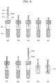
FIG. 9 is a schematic diagram of the dispensing sequence in which the segmented air amount is corrected in accordance with pressure. - In the following, an embodiment of the present invention will be described with reference to the drawings.
- An automatic analysis device is a device for automatically analyzing the components of a biological sample, such as blood or urine. The device includes a dispensing device for collecting and dispensing liquid from a sample container or a reagent container into a reaction container.
FIG. 1 is a schematic diagram of an overall configuration example of the automatic analysis device. The automatic analysis device is provided with asample rack 101 in which a plurality ofsample containers 100 containing samples is disposed; areagent disc 103 on which a plurality ofreagent bottles 102 containing reagents is disposed; acell disc 105 on which a plurality ofreaction cells 104 for mixing sample and reagent into a reaction liquid is disposed; asample dispensing mechanism 106 capable of moving a certain quantity of sample from within thesample containers 100 into thereaction cells 104; and areagent dispensing mechanism 107 capable of moving a certain quantity of reagent from within thereagent bottles 102 into thereaction cells 104. The automatic analysis device is also provided with a stirringunit 108 for stirring and mixing the sample and reagent in thereaction cells 104; ameasurement unit 109 for irradiating the reaction liquid in thereaction cells 104 with light and receiving resultant light; awashing unit 110 for washing thereaction cells 104; acomputer 111 for controlling the driving of various parts of the analysis device, reading measurement data, and storing and analyzing data; aninput device 112 capable of inputting necessary data into thecomputer 111 from the outside; and anoutput device 113 capable of displaying and outputting data to the outside. - An analysis of the amounts of components in a sample is performed by the following procedure. First, a certain quantity of a sample in the
sample container 100 is dispensed into thereaction cell 104 by thesample dispensing mechanism 106. Then, a certain quantity of a reagent in thereagent bottle 102 is dispensed into thereaction cell 104 by thereagent dispensing mechanism 107. The sample and reagent in thereaction cell 104 are stirred by the stirringunit 108, producing a reaction liquid. If necessary, a plurality of reagents may be additionally dispensed into thereaction cell 104 by thereagent dispensing mechanism 107. During those dispensing processes, thesample container 100, thereagent bottle 102, and thereaction cell 104 are moved to predetermined positions by the transport of thesample rack 101 and rotation of thereagent disc 103 and thecell disc 105. After completion of the reaction, the inside of thereaction cell 104 is washed by thewashing mechanism 110 for the next analysis. The absorbance of the reaction liquid is measured by themeasurement unit 109, and absorbance data are accumulated in thecomputer 111. From the accumulated absorbance data, thecomputer 111 analyzes the component amounts on the basis of calibration curve data and the Lambert-Beer law. The data necessary for controlling various units and analysis are input from theinput device 112 into thecomputer 111. Various data and analysis results are displayed and output by theoutput device 113. -
FIG. 2 is a schematic diagram of a configuration example of the dispensing mechanism. On ashaft 114 that can be driven up and down, anarm 115 that can be rotationally driven is installed. At the end of thearm 115, a dispensingprobe 116 is installed. The dispensingprobe 116, apressure sensor 117, and asyringe pump 118 are connected viapiping 119. The dispensing flow passageway has the distal side thereof opened via thedispensing probe 116, with the proximal side thereof being configured to be opened and closed by anelectromagnetic valve 120. During liquid dispensing operation, theelectromagnetic valve 120 is closed so as to suction or discharge the sample or reagent via the tip of the dispensingprobe 116 by the movement of aplunger 121 installed in thesyringe pump 118. After completion of the dispensing operation, the electromagnetic valve is opened to supply washing water from the proximal side. - As a comparative example, a conventional liquid sample dispensing sequence under the atmospheric pressure will be described with reference to a schematic diagram shown in
FIG. 3 . -
FIG. 3(a) illustrates a sealedsample container 100 immediately prior to the insertion of the dispensingprobe 116 therein. In this example, the pressure inside thesample container 100 is the same as the pressure outside thesample container 100, i.e., the atmospheric pressure. The dispensingprobe 116 is filled withwater 122 for transmitting the pressure from thesyringe pump 118. Into the tip of the dispensingprobe 116,segmented air 123 is suctioned in advance, thus forming an air layer for preventing thesample 124, as it is being suctioned, from being mixed with and diluted by thewater 122. Thereafter, as illustrated inFIG. 3(b) , the dispensingprobe 116 is inserted into thesample container 100 via arubber plug 125 until reaching inside the liquid of thesample 124. Then, as illustrated inFIG. 3(c) , thesample 124 is suctioned into the dispensingprobe 116. As illustrated inFIG. 3(d) , the dispensingprobe 116 is then removed out of thesample container 100. Finally, as illustrated inFIG. 3(e) , the dispensingprobe 116 is moved into thereaction cell 104, and the suctionedsample 124 is discharged into thereaction cell 104, as illustrated inFIG. 3(f) . - Next, a dispensing sequence in the case where the inside of the sealed
sample containers 100 is at negative pressure will be described with reference to a schematic diagram shown inFIG. 4 . Also, the difference from the case where the reagent container has the atmospheric pressure will be described with reference toFIG. 5 illustrating a temporal change in pressure in the dispensing flow passageway. InFIG. 5 , illustrating the pressure variation in the dispensing flow passageway, the solid line indicates the case where the sample container has negative pressure, and the broken line indicates the case where the sample container has the atmospheric pressure. -
FIG. 4(a) illustrates the dispensingprobe 116 filled with thewater 122, with thesegmented air 123 suctioned therein. As thesegmented air 123 is suctioned, the pressure in the dispensing flow passageway decreases during the suction operation, as illustrated in the pressure data ofFIG. 5 between times t0 to t1. As thedispensing probe 116 is inserted into thesample container 100 as illustrated inFIG. 4(b) , the dispensing flow passageway and thesample container 100 are hermetically connected. When the inside of thereagent container 100 is at the atmospheric pressure, no change is caused in the pressure in the dispensing flow passageway, as illustrated in the pressure data ofFIG. 5 between times t2 and t3. However, in the case of negative pressure, the pressure decreases from P0 to P1. As a result, the dispensing flow passageway contracts as a whole, and the interface of thewater 122 in thedispensing probe 116 moves toward thesample container 100, whereby the volume of thesegmented air 123 in thedispensing probe 116 decreases. - Then, as illustrated in
FIG. 4(c) , the dispensingprobe 116 reaches thesample 124 in thesample container 100, and thesample 124 is suctioned into the dispensingprobe 116, as illustrated inFIG. 4(d) . At this time, the pressure in the dispensing flow passageway decreases during the suction operation, as illustrated inFIG. 5 between time t4 to t5. Thereafter, as illustrated inFIG. 4(e) to (f) , as the dispensingprobe 116 is removed out of thesample container 100, the hermetic connection of the dispensing flow passageway and thesample container 100 is released. At this time, if the inside of thesample container 100 is at the atmospheric pressure, no change is caused in the pressure of the dispensing flow passageway, as illustrated in the pressure data ofFIG. 5 from time t6 to t7. However, if the internal pressure is negative, the pressure in the dispensing flow passageway is exposed to the atmosphere and turns from P1 to P0. As a result, the flow passageway as a whole expands, whereby the interface of thewater 122, thesegmented air 123, and thesample 124 in thedispensing probe 116 are moved from the tip toward the proximal side, and air enters the tip of the dispensingprobe 116. Finally, as illustrated inFIG. 4(g) , the dispensingprobe 116 is moved into thereaction cell 104, and the suctionedsample 124 is discharged into thereaction cell 105 as illustrated in FIG. 4(i). When the inside of thesample container 100 is at negative pressure, the discharge amount relative to the amount of operation of the pump becomes insufficient because of the entry of air into the tip. - Accordingly, in the present example, in order to eliminate the lack of discharge amount, the amount of discharge operation is corrected in accordance with the pressure in the sealed
sample container 100. A sequence of the present example will be described with reference to a flowchart shown inFIG. 6 and a schematic diagram shown inFIG. 7 . - Referring to
FIG. 6 , after the start of the dispensing operation, thesegmented air 123 is suctioned in step 11 (FIG. 7(a) ). Instep 12, the atmospheric pressure is measured. This is performed at time t1 inFIG. 5 , whereby the atmospheric pressure P0 is obtained. In step 13, the dispensingprobe 116 is inserted via therubber plug 125 into the air layer in the sealed sample container 100 (FIG. 7(b) ). Instep 14, the pressure inside thesample container 100 is measured. This step is performed at time t3 inFIG. 5 , whereby pressure P1 is obtained. The atmospheric pressure P0 outside thesample container 100 and the internal pressure P1 having been acquired, a sample discharge correction amount is calculated instep 15. A method for calculating the correction amount will be described later. - Thereafter, in
step 16, the dispensingprobe 116 is lowered to the sample layer (FIG. 7(c) ), and thesample 124 is suctioned in step 17 (FIG. 7(d) ). In step 18, as the dispensingprobe 116 is removed from thesample container 100, the pressure in the dispensing flow passageway is opened to the atmospheric pressure, and air enters the tip of the dispensingprobe 116, as illustrated inFIG. 7(f) . Finally, the dispensingprobe 116 is inserted into the reaction cell 104 (FIG. 7(g) ), and thesample 124 is discharged into thereaction cell 104 instep 19 by applying the sample discharge correction amount obtained instep 15 in consideration of the lack due to the entry of air (FIG. 7(h) ), and the sequence ends. - While the example has been described in which the atmospheric pressure P0 is measured at time t1 in
FIG. 5 , a similar result will be obtained when the measurement is conducted between times t7 and t8 in which thedispensing probe 116 is removed from thesample container 100. Alternatively, the measurement may be conducted at both timings to obtain an average so as to effectively increase the pressure measurement accuracy. Also, the pressure inside thesample container 100 may be measured between t5 and t6 rather than at time t3 inFIG. 5 , or at both timings. In addition, while the example has been described in which thedispensing probe 116 is lowered to the air layer of thesample container 100 in step 13, and the pressure measurement is conducted instep 14 when the lowering is stopped, the pressure measurement may be conducted during the lowering as long as the measurement is not affected by vibrations and the like during operation. Further, if there is sufficient time for a pressure variation to become stabilized after thedispensing probe 116 is inserted into thesample container 100 and before reaching the sample layer, the dispensingprobe 116 may not be stopped at the air layer but may be continuously lowered. The pressure measurement is also possible with the dispensingprobe 116 immersed in the sample layer. - A method for calculating the sample discharge correction amount from the atmospheric pressure P0 outside the
sample container 100 and the internal pressure P1 will be described. The lack of discharge amount due to the pressure change corresponds to the amount of air Vcor that has entered the tip of the dispensingprobe 116 as illustrated inFIG. 7(f) , and is caused by deformation of the dispensing flow passageway and a volume change in thesegmented air 123. Accordingly, the correction amount can be determined by calculating the relevant amounts of change. - As illustrated in
FIG. 2 , the dispensing flow passageway includes the dispensingprobe 116, thepressure sensor 117, thesyringe pump 118, and the piping 119 connecting them. For example, the piping 119 is cylindrical and has an inner diameter rin, an outer diameter rout, a length 1, a Young's modulus E, and a Poisson's ratio v. When the piping 119 is subjected to internal pressure Pin and external pressure Pout, the amount of change in inner diameter Δrin and the amount of change in length Δl can be computed as follows:

- When the dispensing
probe 116 is inserted in thesample container 100, Pout = P0 and Pin = P1, so that both Δrin and Δl can be derived. Accordingly, the amount of deformation ΔVtube of the piping 119 can be calculated as follows:
- By calculating the above for all of the constituent components and summing the results, the amount of deformation ΔVfc of the flow passageway as a whole is determined. Then, a change in volume of the
segmented air 123 is determined. When the suctioned amount of thesegmented air 123 is Vair, and in view of the fact that the amount of deformation ΔVfc of the piping when the dispensingprobe 116 is inserted into thesample container 100 corresponds to the amount of leakage of thesegmented air 123, the amount of volume change ΔVair due to pressure at the time of removal can be calculated as follows:
- From the above calculation results, the eventual sample discharge correction amount Vcor and the discharge amount Vdspc after correction (the discharge amount before correction: Vdsp) can be determined as follows:


- These computations may be performed in real time during the sequence based on the pressure measurement results. Alternatively, data about the relationship between pressure and correction amount may be stored in advance, and a corresponding correction amount may be read based on a pressure measurement result.
- In this example, a method for correcting the amount of the
segmented air 123 and the discharge amount will be described. - As illustrated in
FIG. 4 , the amount of thesegmented air 123 varies depending on the pressure inside the sealedsample container 100. Thesegmented air 123 serves to prevent the sample from being diluted by the entry of thewater 122, which transmits the pressure from the syringe pump, into the suctioned sample. However, dilution may not be completely avoided, and the way the sample is diluted may differ depending on the amount of the segmented air. In addition, when thesample 124 is suctioned, thesegmented air 123 may expand or contract, and the time between the end of suctioning and pressure stabilization may be greatly influenced by the expansion or contraction, depending on the viscosity of the sample. For any of these problems, it is effective to perform correction so that the amount of thesegmented air 123 becomes constant regardless of the pressure inside thesample container 100. - An example of a dispensing sequence involving a pump operation correction for achieving a constant amount of the
segmented air 123 will be described with reference to a flowchart shown inFIG. 8 and a schematic diagram shown inFIG. 9 . - After the start of the dispensing operation, the
segmented air 123 is suctioned in step 21 (FIG. 9(a) ). At this time, a greater amount ofsegmented air 123 than will eventually be held in thedispensing probe 116 is suctioned to allow for the adjustment by the correction operation. Then, instep 22, the atmospheric pressure is measured. This is performed at time t1 inFIG. 5 , whereby the atmospheric pressure P0 is obtained. Instep 23, the dispensingprobe 116 is inserted via therubber plug 125 into the air layer of the sealed sample container 100 (FIG. 9(b) ), and the pressure inside thesample container 100 is measured instep 24. This step is performed at time t3 inFIG. 5 , whereby pressure P1 is obtained. The atmospheric pressure P0 outside thesample container 100 and the internal pressure P1 having been acquired, air discharge and air suction correction amounts are calculated instep 25. A method for calculating the correction amounts will be described later. Instep 26, an air discharge operation is performed by applying the result of the correction amount calculation instep 25 so as to achieve a constant amount of the segmented air 123 (FIG. 9(c) ). - Thereafter, in
step 27, the dispensingprobe 116 is lowered to the sample layer (FIG. 9(d) ), and thesample 124 is suctioned in step 28 (FIG. 9(e) ). This is followed by lifting the dispensingprobe 116 up to the air layer in step 29 (FIG. 9(f) ), and an air suction operation is performed instep 30 by applying the result of the correction amount calculation instep 25 in consideration of the amount of air that enters the tip when the pressure in the dispensing flow passageway returns to the atmospheric pressure (FIG. 9(g) ). Further, as the dispensingprobe 116 is removed from thesample container 100 in step 31 (FIG. 9(h) ), the internal pressure of the dispensing flow passageway is opened to the atmospheric pressure, allowing air to enter the tip of the dispensingprobe 116, as described above. If the inside of thesample container 100 is at positive pressure, as the positive pressure is opened to the atmospheric pressure, the dispensing flow passageway will contract and thesample 124 may leak from the dispensingprobe 116. However, when the air suction operation has been performed in consideration of the amount of deformation of the dispensing flow passageway instep 30, the leakage of thesample 124 can also be avoided. Accordingly, at the end of step 31, thesample 124 can be held at a constant position in thedispensing probe 116 regardless of the pressure inside thesample container 100. Finally, the dispensingprobe 116 is inserted into the reaction cell 104 (FIG. 9(i) ), thesample 124 is discharged into thereaction cell 104 in step 32 (FIG. 9(j) ), and the sequence ends. While in the foregoing example, the discharge operation is performed instep 26, a suction operation may be performed instead, given that the purpose is to make the amount of thesegmented air 123 constant in accordance with the pressure inside thesample container 100. Whether a suction or discharge operation is performed may be selected depending on the pressure. - A method for calculating the air discharge/suction correction amount from the atmospheric pressure P0 outside the
sample container 100 and the internal pressure P1 will be described. As described above, the difference in the amount of thesegmented air 123 or the position of the suctioned sample due to pressure is caused by the deformation of the dispensing flow passageway and a volume change in thesegmented air 123. The amount of deformation ΔVfc of the dispensing flow passageway can be calculated from the physical property values and sizes of the flow passageway constituent elements and the pressure applied, as described with reference to Example 1. - A method for calculating the corrected discharge amount Vcor1 in
step 26 ofFIG. 8 will be described. When the suctioned amount of thesegmented air 123 instep 21 is Vaira (FIG. 9(a) ) and the target amount of thesegmented air 123 being held after removal of the dispensingprobe 116 from thesample container 100 is Vairt (FIG. 9(h) ), the corrected discharge amount can be determined as follows:
- A method for calculating the corrected suctioned amount Vcor2 in
step 30 will be described. In order to control the amount of air being held under thesample 124 in thedispensing probe 116 after removal of the dispensingprobe 116 from thesample containers 100 to become Vairc (FIG. 9(h) ), the corrected suctioned amount Vcor2 is set as follows:
- Then, when sample discharge is performed in step 32, the sum of the amount of air Vairc being held in the tip of the dispensing
probe 116 and the amount of sample to be discharged into thereaction cell 105 is set as the amount of operation of the pump. The results of these calculations are also valid whether the pressure inside thesample container 100 is the atmospheric pressure, negative pressure, or positive pressure. - The present invention is not limited to the foregoing examples, and may include various modifications. The examples have been described for facilitating an understanding of the present invention, and are not necessarily limited to be provided with all of the described features. Some of the features of one example may be substituted by features of another example, or a feature of the other example may be added to the features of the one example. With respect to some of the features of each example, addition of another feature, deletion, or substitution may be made.
-
- 100
- Sample container
- 104
- Reaction cell
- 114
- Shaft
- 115
- Arm
- 116
- Dispensing probe
- 117
- Pressure sensor
- 118
- Syringe pump
- 119
- Piping
- 120
- Electromagnetic valve
- 121
- Plunger
- 122
- Water
- 123
- Segmented air
- 124
- Sample
- 125
- Rubber plug
Claims (12)
- A dispensing device comprising:a pump;a probe connected to the pump via a piping;a pressure sensor that measures a pressure in the piping; anda control unit that controls the pump and the probe and that reads a signal from the pressure sensor,wherein, when a liquid is dispensed from a sealed container, the control unit measures pressures outside and inside the container using the pressure sensor, and corrects the amount of operation of the pump in accordance with the measured pressures.
- The dispensing device according to claim 1, wherein the control unit measures the pressure inside the container with the probe inserted into the container.
- The dispensing device according to claim 1, wherein the control unit corrects the amount of operation of the pump for discharging the liquid.
- The dispensing device according to claim 1, the control unit corrects the amount of operation of the pump for suctioning or discharging air into or out of the probe.
- The dispensing device according to claim 1, wherein the control unit calculates the amount of deformation of a dispensing flow passageway due to a pressure change, and corrects the amount of operation of the pump based on the amount of deformation.
- The dispensing device according to claim 1, wherein the control unit causes the probe to be removed from the container after the liquid is suctioned by inserting the probe, with a segmented air suctioned therein, into the container, and then causes the probe to discharge the suctioned liquid by applying the corrected amount of operation in the pump.
- The dispensing device according to claim 1, wherein the control unit causes the probe with a segmented air suctioned therein to be inserted into the container, controls the pump to discharge or suction the segmented air so that the amount of the segmented air becomes a predetermined amount with the probe removed from the container, and further controls the pump, after the liquid in the container is suctioned, to suction air from within the container into a tip of the probe so that the air has a predetermined amount with the probe removed from the container.
- A dispensing method comprising:a step of suctioning a segmented air into a probe;a step of measuring a pressure outside a sealed container;a step of measuring a pressure inside the container;a step of calculating a correction amount for a discharge amount required for discharging a liquid suctioned by the probe from the container, based on the measured external and internal pressures;a step of suctioning into the probe the liquid held in the container;a step of removing the probe from the container; anda step of discharging the suctioned liquid from the probe by applying the correction amount for the discharge amount.
- The dispensing method according to claim 8, wherein:the pressure measurement is performed by a pressure sensor connected to the probe;the external pressure is measured before the probe is inserted into the container or after the probe is removed therefrom; andthe internal pressure is measured before the liquid is suctioned by inserting the probe into the container or before the probe is removed from the container after the suctioning.
- The dispensing method according to claim 8, wherein the internal pressure is measured by inserting the probe into the container and having a tip of the probe stopped in an air layer of the container.
- The dispensing method according to claim 8, wherein the correction amount for the discharge amount is calculated based on an amount of deformation of a dispensing flow passageway due to a pressure change and an amount of the segmented air that leaks from the probe when the probe is inserted into the container.
- A dispensing method comprising:a step of suctioning a segmented air into a probe;a step of measuring a pressure outside a sealed container;a step of inserting the probe into the container;a step of measuring a pressure inside the container;a step of discharging or suctioning the segmented air, based on the measured external and internal pressures, so that the amount of the segmented air becomes a predetermined amount with the probe removed from the container;a step of suctioning into the probe a liquid held in the container;a step of suctioning air from within the container into a tip of the probe so that the air has a predetermined amount with the probe removed from the container;a step of removing the probe from the container; anda step of discharging the suctioned liquid from the probe.
Applications Claiming Priority (2)
| Application Number | Priority Date | Filing Date | Title |
|---|---|---|---|
| JP2014046704A JP6230450B2 (en) | 2014-03-10 | 2014-03-10 | Dispensing device and dispensing method |
| PCT/JP2015/051597 WO2015136991A1 (en) | 2014-03-10 | 2015-01-22 | Dispensing device and dispensing method |
Publications (3)
| Publication Number | Publication Date |
|---|---|
| EP3118629A1 true EP3118629A1 (en) | 2017-01-18 |
| EP3118629A4 EP3118629A4 (en) | 2017-11-29 |
| EP3118629B1 EP3118629B1 (en) | 2018-11-07 |
Family
ID=54071445
Family Applications (1)
| Application Number | Title | Priority Date | Filing Date |
|---|---|---|---|
| EP15761890.1A Active EP3118629B1 (en) | 2014-03-10 | 2015-01-22 | Dispensing device and dispensing method |
Country Status (5)
| Country | Link |
|---|---|
| US (1) | US9927453B2 (en) |
| EP (1) | EP3118629B1 (en) |
| JP (1) | JP6230450B2 (en) |
| CN (1) | CN105899954B (en) |
| WO (1) | WO2015136991A1 (en) |
Families Citing this family (12)
| Publication number | Priority date | Publication date | Assignee | Title |
|---|---|---|---|---|
| CN106471374B (en) | 2014-07-18 | 2018-12-14 | 株式会社日立高新技术 | Liquid stirring method |
| JP6676300B2 (en) * | 2015-07-28 | 2020-04-08 | ヤマハ発動機株式会社 | Object moving method and device |
| JP6710850B1 (en) | 2017-04-20 | 2020-06-17 | バイオフルイディカ、インコーポレイテッド | Fluid-tight flow system for isolation of biomarkers from liquid samples |
| JPWO2020235585A1 (en) * | 2019-05-22 | 2020-11-26 | ||
| JP7292999B2 (en) | 2019-06-25 | 2023-06-19 | キヤノンメディカルシステムズ株式会社 | Reagent container and automatic analysis system |
| DE102020204687A1 (en) * | 2020-04-14 | 2021-10-14 | Bruker Biospin Gmbh | Automatic verification and recalibration of a pump delivery volume |
| JP7417463B2 (en) * | 2020-04-24 | 2024-01-18 | 株式会社日立ハイテク | Dispensing device, automatic analyzer, dispensing method |
| EP4164795A4 (en) | 2020-06-12 | 2024-01-24 | BioFluidica, Inc. | DOUBLE-DEPTH THERMOPLASTIC MICROFLUIDIC DEVICE AND RELATED SYSTEMS AND METHODS |
| JP7685128B2 (en) * | 2020-07-28 | 2025-05-29 | 株式会社Dfc | Raw material storage case and raw material suction device using the same |
| WO2023042276A1 (en) | 2021-09-14 | 2023-03-23 | 株式会社日立ハイテク | Dispensing device and dispensing method |
| CN117980748A (en) | 2021-09-14 | 2024-05-03 | 株式会社日立高新技术 | Dispensing device and dispensing method |
| US12226776B2 (en) | 2021-11-04 | 2025-02-18 | Instrumentation Laboratory Company | Preparing substances in a medical diagnostic system |
Family Cites Families (13)
| Publication number | Priority date | Publication date | Assignee | Title |
|---|---|---|---|---|
| JP3318629B2 (en) * | 1993-06-18 | 2002-08-26 | ソニー株式会社 | Liquid suction / discharge device and method |
| US5918291A (en) * | 1995-06-07 | 1999-06-29 | Inacu; Fulga | Method for liquid aspiration from a sealed container |
| JP3678527B2 (en) | 1996-03-14 | 2005-08-03 | シスメックス株式会社 | Sample suction tube |
| US6322752B1 (en) * | 1999-09-08 | 2001-11-27 | Coulter International Corp. | Method and apparatus for aspirating and dispensing liquids |
| US7510684B2 (en) | 2001-02-09 | 2009-03-31 | Beckman Coulter, Inc. | Latch system and modified blade design for thick stopper-closed container sampling piercing station |
| JP3779649B2 (en) * | 2002-06-14 | 2006-05-31 | アロカ株式会社 | Dispensing device |
| EP1877805B1 (en) * | 2005-05-06 | 2020-12-23 | Instrumentation Laboratory Company | Telescoping closed-tube sampling assembly |
| US8974750B2 (en) | 2007-12-27 | 2015-03-10 | Horiba, Ltd. | Nozzle device and liquid sample analyzer |
| JP4988541B2 (en) * | 2007-12-27 | 2012-08-01 | 株式会社堀場製作所 | Nozzle device and liquid sample analyzer |
| JP5274124B2 (en) * | 2008-07-02 | 2013-08-28 | ベックマン コールター, インコーポレイテッド | Dispensing device |
| JP5295069B2 (en) | 2009-10-09 | 2013-09-18 | ベックマン コールター, インコーポレイテッド | Dispensing device, analyzer, and dispensing method |
| JP5736280B2 (en) * | 2011-09-06 | 2015-06-17 | 株式会社日立ハイテクノロジーズ | Automatic analyzer |
| EP2719461B8 (en) * | 2012-10-12 | 2023-08-16 | F. Hoffmann-La Roche AG | Method of pipetting a test liquid |
-
2014
- 2014-03-10 JP JP2014046704A patent/JP6230450B2/en active Active
-
2015
- 2015-01-22 US US15/106,881 patent/US9927453B2/en active Active
- 2015-01-22 WO PCT/JP2015/051597 patent/WO2015136991A1/en not_active Ceased
- 2015-01-22 CN CN201580003441.XA patent/CN105899954B/en active Active
- 2015-01-22 EP EP15761890.1A patent/EP3118629B1/en active Active
Also Published As
| Publication number | Publication date |
|---|---|
| EP3118629B1 (en) | 2018-11-07 |
| US9927453B2 (en) | 2018-03-27 |
| JP6230450B2 (en) | 2017-11-15 |
| CN105899954B (en) | 2017-07-07 |
| CN105899954A (en) | 2016-08-24 |
| US20160341756A1 (en) | 2016-11-24 |
| JP2015169623A (en) | 2015-09-28 |
| WO2015136991A1 (en) | 2015-09-17 |
| EP3118629A4 (en) | 2017-11-29 |
Similar Documents
| Publication | Publication Date | Title |
|---|---|---|
| US9927453B2 (en) | Dispensing device and dispensing method | |
| US5918291A (en) | Method for liquid aspiration from a sealed container | |
| US10031152B2 (en) | Automatic analyzer | |
| EP3144678A1 (en) | Automated analysis device | |
| JP6567890B2 (en) | Automatic analyzer | |
| EP2512679B1 (en) | Test tube for diagnostic analyses | |
| EP3605111B1 (en) | Automated analyzer | |
| US11726009B2 (en) | Method and device for measuring the oxygen content of the headspace gas in a container | |
| JP2011106828A (en) | Dispensing device, automated analysis apparatus, and dispensing method | |
| US11561154B2 (en) | Method and device for measuring an oxygen content of a headspace gas in a beverage can | |
| JPS63109373A (en) | Sampling method and apparatus therefor | |
| JP6368536B2 (en) | Automatic analyzer and analysis method | |
| JPS63109330A (en) | Method and apparatus for detecting liquid level | |
| ES2198134T3 (en) | PROCEDURE AND APPLIANCE TO REMOVE LIQUID SAMPLES FROM A CLOSED CONTAINER. | |
| CN213113328U (en) | Quick detection device of nucleic acid amplification product | |
| CN211292270U (en) | A storage tube for quality control analytes | |
| JPS58105066A (en) | Suction/discharge apparatus for automatic chemical analyzer | |
| JP3120180U (en) | Automatic analyzer | |
| JPS6224151A (en) | Suction discharger for automatic chemical analyzer | |
| US20240264193A1 (en) | Dispensing Device, Automatic Analysis Device, and Dispensing Method | |
| EP4481399A1 (en) | Automated analyzing device, and control method for same | |
| CN114323783B (en) | Sampling method, sampling assembly and sample analyzer | |
| JPS61260165A (en) | Sampling monitor for automatic chemical analyzer | |
| WO2010150502A1 (en) | Automatic analysis device | |
| JPS5940138A (en) | Suction and discharge device in automatic chemical analysis device |
Legal Events
| Date | Code | Title | Description |
|---|---|---|---|
| PUAI | Public reference made under article 153(3) epc to a published international application that has entered the european phase |
Free format text: ORIGINAL CODE: 0009012 |
|
| STAA | Information on the status of an ep patent application or granted ep patent |
Free format text: STATUS: REQUEST FOR EXAMINATION WAS MADE |
|
| 17P | Request for examination filed |
Effective date: 20160628 |
|
| AK | Designated contracting states |
Kind code of ref document: A1 Designated state(s): AL AT BE BG CH CY CZ DE DK EE ES FI FR GB GR HR HU IE IS IT LI LT LU LV MC MK MT NL NO PL PT RO RS SE SI SK SM TR |
|
| AX | Request for extension of the european patent |
Extension state: BA ME |
|
| DAX | Request for extension of the european patent (deleted) | ||
| A4 | Supplementary search report drawn up and despatched |
Effective date: 20171030 |
|
| RIC1 | Information provided on ipc code assigned before grant |
Ipc: G01N 35/10 20060101AFI20171024BHEP Ipc: G01F 22/02 20060101ALI20171024BHEP Ipc: B01L 3/02 20060101ALI20171024BHEP |
|
| GRAP | Despatch of communication of intention to grant a patent |
Free format text: ORIGINAL CODE: EPIDOSNIGR1 |
|
| STAA | Information on the status of an ep patent application or granted ep patent |
Free format text: STATUS: GRANT OF PATENT IS INTENDED |
|
| INTG | Intention to grant announced |
Effective date: 20180518 |
|
| GRAS | Grant fee paid |
Free format text: ORIGINAL CODE: EPIDOSNIGR3 |
|
| GRAA | (expected) grant |
Free format text: ORIGINAL CODE: 0009210 |
|
| STAA | Information on the status of an ep patent application or granted ep patent |
Free format text: STATUS: THE PATENT HAS BEEN GRANTED |
|
| AK | Designated contracting states |
Kind code of ref document: B1 Designated state(s): AL AT BE BG CH CY CZ DE DK EE ES FI FR GB GR HR HU IE IS IT LI LT LU LV MC MK MT NL NO PL PT RO RS SE SI SK SM TR |
|
| REG | Reference to a national code |
Ref country code: GB Ref legal event code: FG4D |
|
| REG | Reference to a national code |
Ref country code: CH Ref legal event code: EP Ref country code: AT Ref legal event code: REF Ref document number: 1062710 Country of ref document: AT Kind code of ref document: T Effective date: 20181115 |
|
| REG | Reference to a national code |
Ref country code: DE Ref legal event code: R096 Ref document number: 602015019560 Country of ref document: DE |
|
| REG | Reference to a national code |
Ref country code: IE Ref legal event code: FG4D |
|
| REG | Reference to a national code |
Ref country code: NL Ref legal event code: MP Effective date: 20181107 |
|
| REG | Reference to a national code |
Ref country code: LT Ref legal event code: MG4D |
|
| REG | Reference to a national code |
Ref country code: AT Ref legal event code: MK05 Ref document number: 1062710 Country of ref document: AT Kind code of ref document: T Effective date: 20181107 |
|
| PG25 | Lapsed in a contracting state [announced via postgrant information from national office to epo] |
Ref country code: BG Free format text: LAPSE BECAUSE OF FAILURE TO SUBMIT A TRANSLATION OF THE DESCRIPTION OR TO PAY THE FEE WITHIN THE PRESCRIBED TIME-LIMIT Effective date: 20190207 Ref country code: NO Free format text: LAPSE BECAUSE OF FAILURE TO SUBMIT A TRANSLATION OF THE DESCRIPTION OR TO PAY THE FEE WITHIN THE PRESCRIBED TIME-LIMIT Effective date: 20190207 Ref country code: IS Free format text: LAPSE BECAUSE OF FAILURE TO SUBMIT A TRANSLATION OF THE DESCRIPTION OR TO PAY THE FEE WITHIN THE PRESCRIBED TIME-LIMIT Effective date: 20190307 Ref country code: LT Free format text: LAPSE BECAUSE OF FAILURE TO SUBMIT A TRANSLATION OF THE DESCRIPTION OR TO PAY THE FEE WITHIN THE PRESCRIBED TIME-LIMIT Effective date: 20181107 Ref country code: ES Free format text: LAPSE BECAUSE OF FAILURE TO SUBMIT A TRANSLATION OF THE DESCRIPTION OR TO PAY THE FEE WITHIN THE PRESCRIBED TIME-LIMIT Effective date: 20181107 Ref country code: LV Free format text: LAPSE BECAUSE OF FAILURE TO SUBMIT A TRANSLATION OF THE DESCRIPTION OR TO PAY THE FEE WITHIN THE PRESCRIBED TIME-LIMIT Effective date: 20181107 Ref country code: HR Free format text: LAPSE BECAUSE OF FAILURE TO SUBMIT A TRANSLATION OF THE DESCRIPTION OR TO PAY THE FEE WITHIN THE PRESCRIBED TIME-LIMIT Effective date: 20181107 Ref country code: AT Free format text: LAPSE BECAUSE OF FAILURE TO SUBMIT A TRANSLATION OF THE DESCRIPTION OR TO PAY THE FEE WITHIN THE PRESCRIBED TIME-LIMIT Effective date: 20181107 Ref country code: FI Free format text: LAPSE BECAUSE OF FAILURE TO SUBMIT A TRANSLATION OF THE DESCRIPTION OR TO PAY THE FEE WITHIN THE PRESCRIBED TIME-LIMIT Effective date: 20181107 |
|
| PG25 | Lapsed in a contracting state [announced via postgrant information from national office to epo] |
Ref country code: AL Free format text: LAPSE BECAUSE OF FAILURE TO SUBMIT A TRANSLATION OF THE DESCRIPTION OR TO PAY THE FEE WITHIN THE PRESCRIBED TIME-LIMIT Effective date: 20181107 Ref country code: PT Free format text: LAPSE BECAUSE OF FAILURE TO SUBMIT A TRANSLATION OF THE DESCRIPTION OR TO PAY THE FEE WITHIN THE PRESCRIBED TIME-LIMIT Effective date: 20190307 Ref country code: SE Free format text: LAPSE BECAUSE OF FAILURE TO SUBMIT A TRANSLATION OF THE DESCRIPTION OR TO PAY THE FEE WITHIN THE PRESCRIBED TIME-LIMIT Effective date: 20181107 Ref country code: RS Free format text: LAPSE BECAUSE OF FAILURE TO SUBMIT A TRANSLATION OF THE DESCRIPTION OR TO PAY THE FEE WITHIN THE PRESCRIBED TIME-LIMIT Effective date: 20181107 Ref country code: GR Free format text: LAPSE BECAUSE OF FAILURE TO SUBMIT A TRANSLATION OF THE DESCRIPTION OR TO PAY THE FEE WITHIN THE PRESCRIBED TIME-LIMIT Effective date: 20190208 Ref country code: NL Free format text: LAPSE BECAUSE OF FAILURE TO SUBMIT A TRANSLATION OF THE DESCRIPTION OR TO PAY THE FEE WITHIN THE PRESCRIBED TIME-LIMIT Effective date: 20181107 |
|
| PG25 | Lapsed in a contracting state [announced via postgrant information from national office to epo] |
Ref country code: IT Free format text: LAPSE BECAUSE OF FAILURE TO SUBMIT A TRANSLATION OF THE DESCRIPTION OR TO PAY THE FEE WITHIN THE PRESCRIBED TIME-LIMIT Effective date: 20181107 Ref country code: DK Free format text: LAPSE BECAUSE OF FAILURE TO SUBMIT A TRANSLATION OF THE DESCRIPTION OR TO PAY THE FEE WITHIN THE PRESCRIBED TIME-LIMIT Effective date: 20181107 Ref country code: PL Free format text: LAPSE BECAUSE OF FAILURE TO SUBMIT A TRANSLATION OF THE DESCRIPTION OR TO PAY THE FEE WITHIN THE PRESCRIBED TIME-LIMIT Effective date: 20181107 Ref country code: CZ Free format text: LAPSE BECAUSE OF FAILURE TO SUBMIT A TRANSLATION OF THE DESCRIPTION OR TO PAY THE FEE WITHIN THE PRESCRIBED TIME-LIMIT Effective date: 20181107 |
|
| REG | Reference to a national code |
Ref country code: DE Ref legal event code: R097 Ref document number: 602015019560 Country of ref document: DE |
|
| PG25 | Lapsed in a contracting state [announced via postgrant information from national office to epo] |
Ref country code: SM Free format text: LAPSE BECAUSE OF FAILURE TO SUBMIT A TRANSLATION OF THE DESCRIPTION OR TO PAY THE FEE WITHIN THE PRESCRIBED TIME-LIMIT Effective date: 20181107 Ref country code: EE Free format text: LAPSE BECAUSE OF FAILURE TO SUBMIT A TRANSLATION OF THE DESCRIPTION OR TO PAY THE FEE WITHIN THE PRESCRIBED TIME-LIMIT Effective date: 20181107 Ref country code: RO Free format text: LAPSE BECAUSE OF FAILURE TO SUBMIT A TRANSLATION OF THE DESCRIPTION OR TO PAY THE FEE WITHIN THE PRESCRIBED TIME-LIMIT Effective date: 20181107 Ref country code: MC Free format text: LAPSE BECAUSE OF FAILURE TO SUBMIT A TRANSLATION OF THE DESCRIPTION OR TO PAY THE FEE WITHIN THE PRESCRIBED TIME-LIMIT Effective date: 20181107 Ref country code: SK Free format text: LAPSE BECAUSE OF FAILURE TO SUBMIT A TRANSLATION OF THE DESCRIPTION OR TO PAY THE FEE WITHIN THE PRESCRIBED TIME-LIMIT Effective date: 20181107 |
|
| REG | Reference to a national code |
Ref country code: CH Ref legal event code: PL |
|
| PLBE | No opposition filed within time limit |
Free format text: ORIGINAL CODE: 0009261 |
|
| STAA | Information on the status of an ep patent application or granted ep patent |
Free format text: STATUS: NO OPPOSITION FILED WITHIN TIME LIMIT |
|
| PG25 | Lapsed in a contracting state [announced via postgrant information from national office to epo] |
Ref country code: LU Free format text: LAPSE BECAUSE OF NON-PAYMENT OF DUE FEES Effective date: 20190122 |
|
| 26N | No opposition filed |
Effective date: 20190808 |
|
| REG | Reference to a national code |
Ref country code: BE Ref legal event code: MM Effective date: 20190131 |
|
| GBPC | Gb: european patent ceased through non-payment of renewal fee |
Effective date: 20190207 |
|
| REG | Reference to a national code |
Ref country code: IE Ref legal event code: MM4A |
|
| PG25 | Lapsed in a contracting state [announced via postgrant information from national office to epo] |
Ref country code: SI Free format text: LAPSE BECAUSE OF FAILURE TO SUBMIT A TRANSLATION OF THE DESCRIPTION OR TO PAY THE FEE WITHIN THE PRESCRIBED TIME-LIMIT Effective date: 20181107 |
|
| PG25 | Lapsed in a contracting state [announced via postgrant information from national office to epo] |
Ref country code: BE Free format text: LAPSE BECAUSE OF NON-PAYMENT OF DUE FEES Effective date: 20190131 |
|
| PG25 | Lapsed in a contracting state [announced via postgrant information from national office to epo] |
Ref country code: CH Free format text: LAPSE BECAUSE OF NON-PAYMENT OF DUE FEES Effective date: 20190131 Ref country code: LI Free format text: LAPSE BECAUSE OF NON-PAYMENT OF DUE FEES Effective date: 20190131 |
|
| PG25 | Lapsed in a contracting state [announced via postgrant information from national office to epo] |
Ref country code: GB Free format text: LAPSE BECAUSE OF NON-PAYMENT OF DUE FEES Effective date: 20190207 Ref country code: IE Free format text: LAPSE BECAUSE OF NON-PAYMENT OF DUE FEES Effective date: 20190122 |
|
| PG25 | Lapsed in a contracting state [announced via postgrant information from national office to epo] |
Ref country code: TR Free format text: LAPSE BECAUSE OF FAILURE TO SUBMIT A TRANSLATION OF THE DESCRIPTION OR TO PAY THE FEE WITHIN THE PRESCRIBED TIME-LIMIT Effective date: 20181107 |
|
| PG25 | Lapsed in a contracting state [announced via postgrant information from national office to epo] |
Ref country code: MT Free format text: LAPSE BECAUSE OF NON-PAYMENT OF DUE FEES Effective date: 20190122 |
|
| REG | Reference to a national code |
Ref country code: DE Ref legal event code: R081 Ref document number: 602015019560 Country of ref document: DE Owner name: HITACHI HIGH-TECH CORPORATION, JP Free format text: FORMER OWNER: HITACHI HIGH-TECHNOLOGIES CORPORATION, TOKYO, JP |
|
| PG25 | Lapsed in a contracting state [announced via postgrant information from national office to epo] |
Ref country code: CY Free format text: LAPSE BECAUSE OF FAILURE TO SUBMIT A TRANSLATION OF THE DESCRIPTION OR TO PAY THE FEE WITHIN THE PRESCRIBED TIME-LIMIT Effective date: 20181107 |
|
| PG25 | Lapsed in a contracting state [announced via postgrant information from national office to epo] |
Ref country code: HU Free format text: LAPSE BECAUSE OF FAILURE TO SUBMIT A TRANSLATION OF THE DESCRIPTION OR TO PAY THE FEE WITHIN THE PRESCRIBED TIME-LIMIT; INVALID AB INITIO Effective date: 20150122 |
|
| PG25 | Lapsed in a contracting state [announced via postgrant information from national office to epo] |
Ref country code: MK Free format text: LAPSE BECAUSE OF FAILURE TO SUBMIT A TRANSLATION OF THE DESCRIPTION OR TO PAY THE FEE WITHIN THE PRESCRIBED TIME-LIMIT Effective date: 20181107 |
|
| PGFP | Annual fee paid to national office [announced via postgrant information from national office to epo] |
Ref country code: FR Payment date: 20251218 Year of fee payment: 12 |
|
| PGFP | Annual fee paid to national office [announced via postgrant information from national office to epo] |
Ref country code: DE Payment date: 20251217 Year of fee payment: 12 |