EP3118476A1 - Adaptor for power generating system - Google Patents
Adaptor for power generating system Download PDFInfo
- Publication number
- EP3118476A1 EP3118476A1 EP15176912.2A EP15176912A EP3118476A1 EP 3118476 A1 EP3118476 A1 EP 3118476A1 EP 15176912 A EP15176912 A EP 15176912A EP 3118476 A1 EP3118476 A1 EP 3118476A1
- Authority
- EP
- European Patent Office
- Prior art keywords
- adaptor
- generator
- coupling
- flange
- engine
- Prior art date
- Legal status (The legal status is an assumption and is not a legal conclusion. Google has not performed a legal analysis and makes no representation as to the accuracy of the status listed.)
- Granted
Links
- 230000008878 coupling Effects 0.000 claims abstract description 78
- 238000010168 coupling process Methods 0.000 claims abstract description 78
- 238000005859 coupling reaction Methods 0.000 claims abstract description 78
- 238000000034 method Methods 0.000 claims abstract description 16
- 238000010248 power generation Methods 0.000 claims description 17
- 239000007789 gas Substances 0.000 description 6
- 239000002184 metal Substances 0.000 description 4
- 229910052751 metal Inorganic materials 0.000 description 4
- 239000000463 material Substances 0.000 description 3
- 238000005266 casting Methods 0.000 description 2
- 238000002485 combustion reaction Methods 0.000 description 2
- 239000013536 elastomeric material Substances 0.000 description 2
- 238000009434 installation Methods 0.000 description 2
- VNWKTOKETHGBQD-UHFFFAOYSA-N methane Chemical compound C VNWKTOKETHGBQD-UHFFFAOYSA-N 0.000 description 2
- 230000001360 synchronised effect Effects 0.000 description 2
- 229910001141 Ductile iron Inorganic materials 0.000 description 1
- 238000010521 absorption reaction Methods 0.000 description 1
- 230000005540 biological transmission Effects 0.000 description 1
- 238000003754 machining Methods 0.000 description 1
- 239000003345 natural gas Substances 0.000 description 1
- 239000004033 plastic Substances 0.000 description 1
- 238000000926 separation method Methods 0.000 description 1
Images


Classifications
-
- F—MECHANICAL ENGINEERING; LIGHTING; HEATING; WEAPONS; BLASTING
- F16—ENGINEERING ELEMENTS AND UNITS; GENERAL MEASURES FOR PRODUCING AND MAINTAINING EFFECTIVE FUNCTIONING OF MACHINES OR INSTALLATIONS; THERMAL INSULATION IN GENERAL
- F16D—COUPLINGS FOR TRANSMITTING ROTATION; CLUTCHES; BRAKES
- F16D3/00—Yielding couplings, i.e. with means permitting movement between the connected parts during the drive
- F16D3/84—Shrouds, e.g. casings, covers; Sealing means specially adapted therefor
- F16D3/843—Shrouds, e.g. casings, covers; Sealing means specially adapted therefor enclosed covers
-
- F—MECHANICAL ENGINEERING; LIGHTING; HEATING; WEAPONS; BLASTING
- F16—ENGINEERING ELEMENTS AND UNITS; GENERAL MEASURES FOR PRODUCING AND MAINTAINING EFFECTIVE FUNCTIONING OF MACHINES OR INSTALLATIONS; THERMAL INSULATION IN GENERAL
- F16D—COUPLINGS FOR TRANSMITTING ROTATION; CLUTCHES; BRAKES
- F16D3/00—Yielding couplings, i.e. with means permitting movement between the connected parts during the drive
- F16D3/50—Yielding couplings, i.e. with means permitting movement between the connected parts during the drive with the coupling parts connected by one or more intermediate members
- F16D3/54—Couplings comprising a chain or strip surrounding two wheels arranged side by side and provided with teeth or the equivalent
-
- F—MECHANICAL ENGINEERING; LIGHTING; HEATING; WEAPONS; BLASTING
- F16—ENGINEERING ELEMENTS AND UNITS; GENERAL MEASURES FOR PRODUCING AND MAINTAINING EFFECTIVE FUNCTIONING OF MACHINES OR INSTALLATIONS; THERMAL INSULATION IN GENERAL
- F16D—COUPLINGS FOR TRANSMITTING ROTATION; CLUTCHES; BRAKES
- F16D3/00—Yielding couplings, i.e. with means permitting movement between the connected parts during the drive
- F16D3/50—Yielding couplings, i.e. with means permitting movement between the connected parts during the drive with the coupling parts connected by one or more intermediate members
- F16D3/76—Yielding couplings, i.e. with means permitting movement between the connected parts during the drive with the coupling parts connected by one or more intermediate members shaped as an elastic ring centered on the axis, surrounding a portion of one coupling part and surrounded by a sleeve of the other coupling part
-
- H—ELECTRICITY
- H02—GENERATION; CONVERSION OR DISTRIBUTION OF ELECTRIC POWER
- H02K—DYNAMO-ELECTRIC MACHINES
- H02K7/00—Arrangements for handling mechanical energy structurally associated with dynamo-electric machines, e.g. structural association with mechanical driving motors or auxiliary dynamo-electric machines
- H02K7/003—Couplings; Details of shafts
-
- F—MECHANICAL ENGINEERING; LIGHTING; HEATING; WEAPONS; BLASTING
- F02—COMBUSTION ENGINES; HOT-GAS OR COMBUSTION-PRODUCT ENGINE PLANTS
- F02B—INTERNAL-COMBUSTION PISTON ENGINES; COMBUSTION ENGINES IN GENERAL
- F02B63/00—Adaptations of engines for driving pumps, hand-held tools or electric generators; Portable combinations of engines with engine-driven devices
- F02B63/04—Adaptations of engines for driving pumps, hand-held tools or electric generators; Portable combinations of engines with engine-driven devices for electric generators
-
- F—MECHANICAL ENGINEERING; LIGHTING; HEATING; WEAPONS; BLASTING
- F02—COMBUSTION ENGINES; HOT-GAS OR COMBUSTION-PRODUCT ENGINE PLANTS
- F02B—INTERNAL-COMBUSTION PISTON ENGINES; COMBUSTION ENGINES IN GENERAL
- F02B67/00—Engines characterised by the arrangement of auxiliary apparatus not being otherwise provided for, e.g. the apparatus having different functions; Driving auxiliary apparatus from engines, not otherwise provided for
- F02B67/04—Engines characterised by the arrangement of auxiliary apparatus not being otherwise provided for, e.g. the apparatus having different functions; Driving auxiliary apparatus from engines, not otherwise provided for of mechanically-driven auxiliary apparatus
-
- Y—GENERAL TAGGING OF NEW TECHNOLOGICAL DEVELOPMENTS; GENERAL TAGGING OF CROSS-SECTIONAL TECHNOLOGIES SPANNING OVER SEVERAL SECTIONS OF THE IPC; TECHNICAL SUBJECTS COVERED BY FORMER USPC CROSS-REFERENCE ART COLLECTIONS [XRACs] AND DIGESTS
- Y10—TECHNICAL SUBJECTS COVERED BY FORMER USPC
- Y10T—TECHNICAL SUBJECTS COVERED BY FORMER US CLASSIFICATION
- Y10T29/00—Metal working
- Y10T29/49—Method of mechanical manufacture
- Y10T29/49718—Repairing
- Y10T29/49721—Repairing with disassembling
- Y10T29/4973—Replacing of defective part
Definitions
- At least one of the two separable parts may comprise a centering pin which engages with the other separable part. This may help to locate a removable part when it is reinstalled.
- the adaptor is preferably arranged to surround a coupling between the engine and the generator.
- a method of servicing a power generation system comprising a prime mover coupled to a generator via an adaptor, the adaptor comprising two separable parts, the method comprising removing one part of the adaptor while the other part of the adaptor remains connected between the prime mover and the generator in order to provide access to serviceable parts.
Landscapes
- Engineering & Computer Science (AREA)
- General Engineering & Computer Science (AREA)
- Mechanical Engineering (AREA)
- Power Engineering (AREA)
- Connection Of Motors, Electrical Generators, Mechanical Devices, And The Like (AREA)
- Motor Or Generator Frames (AREA)
Abstract
Description
- The present invention relates to an adaptor for connecting a generator to a prime mover in a power generation system, and in particular an adaptor which can facilitate servicing of parts of the system.
- Power generation systems typically comprise a prime mover which drives an electrical generator in order to produce output electrical power. For example, a power generating set may comprise an engine coupled to a generator (alternator). Typically the crankshaft of the engine is mechanically coupled to the shaft of the generator using a coupling.
- In a power generation system it is necessary for the prime mover and the generator to be precisely aligned, to ensure concentricity of the rotating parts. In a generating set this is usually achieved by mounting the engine and the generator on a bed frame. In addition, an adaptor may be used to connect nonrotating parts of the generator and the engine. The adaptor provides additional stability and helps to prevent relative movement between the engine and the generator.
- During the lifetime of the power generation system it may become necessary to service some of the moving parts. For example, in certain generating sets, it may become necessary to service parts such as the coupling between the engine and the generator, and/or the engine or generator bearings.
- Existing power generating systems typically require the generator to be moved to provide access for servicing moving parts. In order to move the generator it must first be disconnected. Following servicing, the generator must be reconnected and the engine and generator re-aligned. As a consequence, the servicing of moving parts can be time consuming, complex and costly. For example, the servicing repair time for the coupling on a typical gas generator set installation may be around 14 to 15 hours.
- Existing adaptors are usually cylindrical, and surround the generator shaft and/or the coupling. Such adaptors are typically formed from a single cast piece of metal. Openings or windows may be provided in the adaptor to allow an operator to connect the rotating parts. However these openings do not normally allow servicing of moving parts.
- According to a first aspect of the present invention there is provided an adaptor for connecting a generator to a prime mover, the adaptor comprising two separable parts.
- The present invention may provide the advantage that, by providing an adaptor comprising two (or more) separable parts, it may be possible for one part to be removed in order to allow access to moving parts. Thus the present invention may simplify the process of servicing moving parts, in comparison to previous techniques.
- Preferably one part of the adaptor can be removed while the other part is connected between the generator and prime mover. This may allow access to moving parts to be provided without requiring the generator and/or engine to be moved. This this arrangement may allow the alignment between the generator and the engine to be maintained.
- Preferably each part of the adaptor is connectable between the generator and the prime mover. For example, each part of the adaptor may comprise a first flange for connection to the engine and a second flange for connection to the generator. Thus each part of the adaptor may be structural, which may help to provide rigidity between the engine and the generator.
- Preferably the removal of one part of the adaptor exposes the inside of the adaptor. Thus, in use, the removal of one part of the adaptor may expose parts which are inside or adjacent to the adaptor, such as a coupling or bearing. This may allow servicing of those parts which would otherwise be inaccessible due to the presence of the adaptor.
- Preferably a part of the adaptor which has been removed can be reinstalled, for example, following the servicing of a moving part. In order to facilitate reinstallation, the removable part of the adaptor may comprise at least one fit bolt. The fit bolt may engage, for example, with the generator or the prime mover. This may help to locate the removable part when it is reinstalled.
- Preferably the two separable parts of the adaptor are connectable, for example by means of bolts or clamps. This can help to ensure that the adaptor has the required mechanical stiffness.
- At least one of the two separable parts may comprise a centering pin which engages with the other separable part. This may help to locate a removable part when it is reinstalled.
- Preferably each separable part comprises a flange for interfacing with the other part. This may help to ensure a connection between the two parts with the required mechanical rigidity. The flanges comprise bolt holes for connecting the two parts. Alternatively some other means such as clamps may be used for connecting the two parts.
- The adaptor may be cylindrical in shape, and is preferably in the form of an open cylinder. This can allow rotating components, such as a generator shaft and/or a coupling, to be located inside the adaptor.
- The two parts of the adaptor may be separable along lines which run in an axial direction between one end of the adaptor and the other. Thus, where the adaptor is in the form of an open cylinder, the lines may run between one open end of the cylinder and the other. However other arrangements are also possible, and for example a removable part of the adaptor may extend along only part of the length of the adaptor in an axial direction.
- The lines of separation between the two parts of the adaptor may be straight, or some other shape such as curved, waved, serrated or castellated. In one embodiment, the lines are substantially parallel to an axis of rotation of the electrical machine, and/or parallel to each other.
- If desired, the adaptor may be separable into three or more different parts. In this case, at least one part may be separable from the or each other part, while at least one part remains connected between the prime mover and the generator.
- The adaptor is preferably arranged to surround a coupling between the engine and the generator. By providing by providing an adaptor comprising two separable parts, it may be possible for one part to be removed in order to allow the coupling to be serviced. Furthermore, it may be possible to access other parts such as bearings for servicing and/or replacement.
- The adaptor may be produced using any appropriate technique such as casting, machining, or a combination of the two. In a preferred embodiment the adaptor is at least initially cast. The cast adaptor may subsequently be machined to produce the final adaptor.
- According to another aspect of the present invention there is provided a power generation system comprising a prime mover, a generator and an adaptor in any of the forms described above.
- The power generation system may further comprise a coupling for connecting rotating components of the generator and the prime mover. The coupling may be a flexible coupling, which may help to dampen vibratory torque in the system and/or act as a fuse in the drive line.
- Flexible couplings typically comprise an elastomeric component, in order to provide the desired flexibility. The elastomeric component may be, for example, rubber or any other appropriate material. In use, the elastomeric component may degrade over time, and may require replacement. This is typically a complex operation requiring removal of the generator and/or engine.
- In a preferred embodiment of the invention, the coupling comprises an elastomeric component which is removable radially from the coupling. This may allow the elastomeric component to be removed and replaced by removing a part of the adaptor.
- The elastomeric component is preferably removable without requiring removal of the generator. Preferably one part of the adaptor is removable to leave an opening while the other part of the adaptor remains in place, and the elastomeric component is removable through the opening.
- In one embodiment, the coupling comprises a hub and a coupling flange, and the elastomeric component is located between the hub and the coupling flange. For example, the elastomeric component may be disc-shaped, and may be located inside the coupling flange. This may provide a compact coupling arrangement.
- In order to allow the elastomeric component to be removed, the coupling may be arranged such that the coupling flange can be moved axially in order to disengage with the elastomeric component. A locking assembly may be provided for holding the coupling together during operation of the power generation system. The locking assembly, when disconnected, may be movable in an axial direction, in order to reveal the hub.
- In one embodiment the coupling comprises two elastomeric components, both of which may be located between the hub and a coupling flange, and both of which may be removable. At least one of the elastomeric components may be located around the hub. One or both of the elastomeric components may be located inside the coupling flange.
- Alternatively, other types of flexible coupling may be used. For example, the elastomeric component may be located adjacent to at least one of the hub and the coupling flange in an axial direction.
- The power generation system may further comprise a bed frame on which the prime mover and generator are mounted. Preferably one part of the adaptor can be removed to provide access to serviceable parts without removing the prime mover or the generator from the bed frame.
- The prime mover may be, for example, an internal combustion engine, such as a gas engine, a diesel engine or a petrol engine, or some other type of prime mover such as a wind or wave turbine. The generator may be any type of electrical generator, such as a synchronous generator or a permanent magnet generator.
- Corresponding methods may also be provided. Thus according to another aspect of the invention there is provided a method of servicing a power generation system comprising a prime mover coupled to a generator via an adaptor, the adaptor comprising two separable parts, the method comprising removing one part of the adaptor while the other part of the adaptor remains connected between the prime mover and the generator in order to provide access to serviceable parts.
- The power generation system may further comprise an elastomeric coupling, and the method may further comprise removing the elastomeric component of the coupling through an opening left by the removed part of the adaptor. Preferably the elastomeric component is removed in a radial direction and/or without moving the generator.
- In the present specification terms such as "radial", "axial", "circumferential" etc. are generally defined with reference to the axis of a generator and/or engine to which the adaptor is to be connected, and/or the longitudinal axis of the adaptor.
- Features of one aspect of the invention may be provided with any other aspect. Apparatus features may be provided with method aspects and vice versa.
- Preferred features of the present invention will now be described, purely by way of example, with reference to the accompanying drawings, in which:
-
Figure 1 shows an overview of a generating set in an embodiment of the present invention; -
Figure 2 shows an adaptor in an embodiment of the present invention; -
Figure 3 shows part of the generating set with the adaptor in place; -
Figure 4 is an exploded view of a coupling for use in an embodiment of the present invention; and -
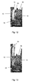
Figures 5 to 13 illustrate a process for replacement of elastomeric components in the coupling. -
Figure 1 shows an overview of a generating set in an embodiment of the present invention. Referring toFigure 1 , the generating set comprises anengine 10 coupled to a generator (alternator) 12. In this embodiment theengine 10 is a gas engine, although any type of internal combustion engine such as a petrol or diesel engine may be used instead. In this embodiment thegenerator 12 is a synchronous generator, although any other type of electrical generator may be used instead. Theengine 10 andgenerator 12 are both mounted on abed frame 14. Acoupling 16 is used to connect the engine flywheel to the shaft of the generator. Anadaptor 18 surrounds the coupling, and is used to connect the engine to the generator housing. Theadaptor 18 helps to prevent relative movement between the engine and the generator, thus ensuring greater stability during operation of the generating set. - In the embodiment of
Figure 1 , thecoupling 16 is a flexible coupling. Flexible couplings are typically used in high power generating sets. For example, high horse power continuous purpose gas generating sets may require a flexible coupling, in particular where a variety of gases such as low BTU natural gas to pipeline gas are used. The flexible coupling can dampen vibratory torque in the system and acts as fuse in the drive line. - Flexible couplings typically include an elastomeric material. The elastomeric material may degrade over time, particularly when subject to high stresses. As a consequence, the life time of a flexible coupling varies depending on its application. In some cases the flexible coupling may fail before the end of its target life. In this case servicing of the coupling may be required outside of a scheduled overhaul of the generator set.
- In existing generator set designs, the adaptor is formed from a single piece of cast metal. Windows may be provided in the adaptor, to allow an operator to connect the coupling once the generator and engine have been aligned. However this does not allow replacement or servicing of the coupling.
- In order to service the coupling in existing generator set designs, the generator set is first shut down. All harnesses and other connections are disconnected, and the generator with adaptor is pulled back from the engine. Following replacement or servicing of the coupling, it is necessary for all parts to be reconnected, and the generator to be re-aligned with the engine.
- As a consequence, replacement or servicing of the coupling is a complex and time consuming process, typically taking 14 to 15 hours depending on the installation. This results in high shutdown costs, both in terms of the servicing required and the lost generating capacity.
- Embodiments of the present invention relate to a new adaptor design and a new flexible coupling which can facilitate servicing without requiring the generator to be moved.
-
Figure 2 shows anadaptor 18 in an embodiment of the present invention. Referring toFigure 2 , theadaptor 18 is generally cylindrical, and comprises afirst flange 22 for connection to the generator and asecond flange 24 for connection to the engine. The first flange and second flange each comprise a number of bolt holes.Bolts 26 pass through the bolt holes in the first flange in order to connect the adaptor to the generator, whilebolts 28 pass through the bolt holes in the second flange in order to connect the adaptor to the engine. In this embodiment cross braces 23 are provided on the outside surface of the adaptor, to help provide structural rigidity.Windows 25 are provided in the adaptor, to allow an operator to lock the coupling on generator shaft once the engine, generator and adaptor are in place. - In the arrangement of
Figure 2 , theadaptor 18 is divided into atop part 30 and abottom part 32. In this embodiment the division occurs in a plane within which the axis of symmetry of the adaptor lies. Thus, in this embodiment the two halves are semi-cylindrical. However the division may occur in different places and the two parts are not necessarily equal. - Still referring to
Figure 2 ,flanges Bolts 40 pass through the bolt holes to connect the two parts together. Two additional centeringpins 42 are provided on each side of the adaptor. The centering pins 42 help to ensure alignment between the two parts of the adaptor. In addition, centeringpins 44 are provided in thesecond flange 24 in thetop part 30. The centering pins 44 help to ensure alignment of thetop part 30 with the engine, in particular following removal of the top part in the way described below. - The
adaptor 18 ofFigure 2 may be made from a cast metal, such as spheroidal graphite cast iron. The adaptor may be machined following casting to provide the appropriate interface surfaces and/or bolt holes. -
Figure 3 shows part of the generating set with theadaptor 18 in place. Referring toFigure 3 , the twoparts adaptor 18 are held together bybolts 40. The adaptor is bolted to theengine 10 withbolts 26, and to thegenerator 12 withbolts 28. -
Figure 4 is an exploded view of a coupling for use in an embodiment of the present invention. Referring toFigure 4 , the coupling comprises ahub 50, twoelastomeric components coupling flange 56, and a lockingassembly 58. Thehub 50 is arranged to be connected to the generator shaft, while thecoupling flange 56 is arranged to be connected to the engine fly wheel. - In the arrangement of
Figure 4 , each of theelastomeric components sleeve elastomeric components sleeves elastomeric components hub 50. - The
hub 50 includes ahub flange 60 with bolt holes 62.Hub bolts 64 pass through the bolt holes 62 and the bolt holes 57, 59 in thesleeves hub 50 to theelastomeric components hub 50 passes through the inside of the secondelastomeric component 54, while the end of thehub 50 engages with thesleeve 53 in the firstelastomeric component 52. - The outside circumferences of the elastomeric components include
castellations 66. Thecoupling flange 56 is generally cylindrical, and fits around theelastomeric components castellations 68, which engage with thecastellations 66 on the outside of theelastomeric components - The
coupling flange 56 includes aflange 70 with bolt holes 72.Flange bolts 74 are used to bolt the coupling flange to the engine fly wheel through the bolt holes 72. Theexternal locking assembly 58 comprisesbolts 76 which are used to hold the coupling together. - The coupling shown in
Figure 4 provides a torsionally soft connection between the engine and the generator. A flexible torque transmission characteristic is achieved by means of theelastomeric components hub 50 and thecoupling flange 56. This can allow the absorption of torsional vibrations and may help to compensate for misalignments. - In use the
elastomeric components Figure 4 may degrade and require replacement.Figures 5 to 13 illustrate a process for replacement of theelastomeric components generator 12. - Referring to
Figure 5 , in step 1 theadaptor bolts 26 connecting the top part of theadaptor 30 to theengine 10, and theadaptor bolts 28 connecting the top part of theadaptor 30 to thegenerator 12, are undone. In addition, thebolts 40 connecting the two parts of the adaptor together are undone. - Referring to
Figure 6 , in step 2 thetop part 30 of the adaptor is removed from the generator set in a radial direction. Removal of the top part of the adaptor exposes thecoupling 16. - Referring to
Figure 7 , in step 3 thebolts 76 of theexternal locking assembly 58 are undone. The lockingassembly 58 is then slid axially along the shaft towards thegenerator 12. This exposes thehub bolts 64. - Referring to
Figure 8 , in step 4 thehub bolts 64 are undone and removed. This disconnects theelastomeric components hub 50. - Referring to
Figure 9 , in step 5 thecoupling flange bolts 74 are undone and removed. This disconnects thecoupling flange 56 from theengine 10. - Referring to
Figure 10 , in step 6 thecoupling flange 56 is slid axially along the shaft towards thegenerator 12. This reveals the firstelastomeric component 52 and part of the secondelastomeric component 54. In this position thecoupling flange 56 is held in place, for example, with a lifting device (not shown). - Referring to
Figure 11 , in step 7 the firstelastomeric component 52 is then removed in a radial direction. Removal of theelastomeric component 52 is possible due to the fact that thehub bolts 64 have been removed and thecoupling flange 56 has been pulled back. - Referring to
Figure 12 , in step 8 the secondelastomeric component 54 is then slid axially along thehub 50 in the direction of theengine 10. This releases theelastomeric component 54 from the hub. - Referring to
Figure 13 , in step 9 the secondelastomeric component 54 is then removed in a radial direction. - The
elastomeric components - Some of the advantages which may be provided by the techniques described above are as follows:
- No need to move the generator back when servicing the coupling
- Fewer steps for disassembly /assembly
- Servicing time reduced by 80% compared to previous techniques
- Less facility space required
- No need to disassemble other subsystems of the generator set, such as wires from the generator
- Lower cost of ownership to the end user.
- In the above, embodiments of the invention have been described by way of example only, and variations in the design are possible. For example, the division between the two parts of the adaptor may be in different places and the two parts are not necessarily equal. It is not necessary for the adaptor to be divided along the whole of its length, and the removable part may extend along only part of the length of the adaptor. If desired, castellations may be provided on the interfaces between the two parts of the adaptor. Furthermore, if desired, the adaptor may comprise three or more parts, the only requirement being that at least one part of the adaptor is separable from the or each other part. Many other variations in detail will be apparent to the skilled person within the scope of the appended claims.
- Although embodiments of the invention have been described with reference to a generator set, the present invention may be used with any type of power generation system where an adaptor is used to connect a prime mover to a generator.
Claims (15)
- An adaptor for connecting a generator to a prime mover, the adaptor comprising two separable parts.
- An adaptor according to claim 1, wherein the adaptor is arranged such that one part of the adaptor can be removed while the other part is connected between the generator and prime mover.
- An adaptor according to claim 1 or 2, wherein each part of the adaptor is connectable between the generator and the prime mover.
- An adaptor according to any of the preceding claims, wherein each part of the adaptor comprises a first flange for connection to the generator and a second flange for connection to the engine.
- An adaptor according to any of the preceding claims, wherein the removal of one part of the adaptor exposes the inside of the adaptor.
- An adaptor according to any of the preceding claims, wherein a removable part of the adaptor comprises at least one centering pin.
- An adaptor according to any of the preceding claims, wherein the two separable parts are connectable by means of bolts.
- An adaptor according to any of the preceding claims, wherein each separable part comprises a flange for interfacing with the other part.
- An adaptor according to any of the preceding claims, wherein the adaptor is arranged to surround a coupling between the engine and the generator.
- A power generation system comprising a prime mover, a generator and an adaptor according to any of the preceding claims.
- A power generation system according to claim 10, further comprising a coupling for connecting rotating components of the generator and the prime mover.
- A power generation system according to claim 11, wherein the coupling comprises an elastomeric component, and the elastomeric component is removable radially from the coupling.
- A power generation system according to claim 12, wherein one part of the adaptor is removable to leave an opening while the other part of the adaptor remains in place, and the elastomeric component is removable through the opening.
- A power generation system according to claim 12 or 13, wherein:the coupling comprises a hub and a coupling flange;the elastomeric component is located between the hub and the coupling flange; andthe coupling flange can be moved axially in order to disengage with the elastomeric component.
- A method of servicing a power generation system comprising a prime mover coupled to a generator via an adaptor, the adaptor comprising two separable parts, the method comprising removing one part of the adaptor while the other part of the adaptor remains connected between the prime mover and the generator in order to provide access to serviceable parts.
Priority Applications (4)
| Application Number | Priority Date | Filing Date | Title |
|---|---|---|---|
| EP18192204.8A EP3447322B1 (en) | 2015-07-15 | 2015-07-15 | Coupling for power generating system |
| EP15176912.2A EP3118476B1 (en) | 2015-07-15 | 2015-07-15 | Adaptor for power generating system |
| US15/210,180 US10428877B2 (en) | 2015-07-15 | 2016-07-14 | Adaptor |
| US16/541,956 US11466733B2 (en) | 2015-07-15 | 2019-08-15 | Coupling for power generation system |
Applications Claiming Priority (1)
| Application Number | Priority Date | Filing Date | Title |
|---|---|---|---|
| EP15176912.2A EP3118476B1 (en) | 2015-07-15 | 2015-07-15 | Adaptor for power generating system |
Related Child Applications (2)
| Application Number | Title | Priority Date | Filing Date |
|---|---|---|---|
| EP18192204.8A Division EP3447322B1 (en) | 2015-07-15 | 2015-07-15 | Coupling for power generating system |
| EP18192204.8A Division-Into EP3447322B1 (en) | 2015-07-15 | 2015-07-15 | Coupling for power generating system |
Publications (2)
| Publication Number | Publication Date |
|---|---|
| EP3118476A1 true EP3118476A1 (en) | 2017-01-18 |
| EP3118476B1 EP3118476B1 (en) | 2018-10-10 |
Family
ID=53886831
Family Applications (2)
| Application Number | Title | Priority Date | Filing Date |
|---|---|---|---|
| EP18192204.8A Active EP3447322B1 (en) | 2015-07-15 | 2015-07-15 | Coupling for power generating system |
| EP15176912.2A Active EP3118476B1 (en) | 2015-07-15 | 2015-07-15 | Adaptor for power generating system |
Family Applications Before (1)
| Application Number | Title | Priority Date | Filing Date |
|---|---|---|---|
| EP18192204.8A Active EP3447322B1 (en) | 2015-07-15 | 2015-07-15 | Coupling for power generating system |
Country Status (2)
| Country | Link |
|---|---|
| US (2) | US10428877B2 (en) |
| EP (2) | EP3447322B1 (en) |
Cited By (1)
| Publication number | Priority date | Publication date | Assignee | Title |
|---|---|---|---|---|
| WO2021013379A1 (en) * | 2019-07-19 | 2021-01-28 | Sew-Eurodrive Gmbh & Co. Kg | Gear motor, comprising a gear mechanism driven via a clutch by an electric motor |
Families Citing this family (3)
| Publication number | Priority date | Publication date | Assignee | Title |
|---|---|---|---|---|
| CN107612185A (en) * | 2017-10-31 | 2018-01-19 | 江苏法兰德电机科技有限公司 | The generator of easy access |
| CN111927622B (en) * | 2020-08-18 | 2021-07-06 | 安徽省英菲尼科技股份有限公司 | Connecting box for diesel engine generator set |
| US20240018858A1 (en) * | 2022-07-12 | 2024-01-18 | Caterpillar Inc. | Electric fracturing drivetrain |
Citations (5)
| Publication number | Priority date | Publication date | Assignee | Title |
|---|---|---|---|---|
| US2736819A (en) * | 1954-03-15 | 1956-02-28 | Napier & Son Ltd | Electric generating unit |
| WO2008039732A2 (en) * | 2006-09-25 | 2008-04-03 | Dresser-Rand Company | Axially moveable spool connector |
| WO2008148142A2 (en) * | 2007-06-06 | 2008-12-11 | Steyr Motors Gmbh | Power generation unit consisting of an internal combustion engine and a generator |
| US20130068049A1 (en) * | 2011-09-17 | 2013-03-21 | Chung Chang | Rotational driveshaft coupler to facilitate a perfect seal |
| GB2515540A (en) * | 2013-06-27 | 2014-12-31 | David Brown Gear Systems Ltd | Coupling |
Family Cites Families (17)
| Publication number | Priority date | Publication date | Assignee | Title |
|---|---|---|---|---|
| US732400A (en) * | 1903-04-10 | 1903-06-30 | Solomon R Dresser | Repair-sleeve for fluid-conducting pipes. |
| US1733771A (en) * | 1928-01-21 | 1929-10-29 | Trinity Wheel Corp | Flexible driving mechanism |
| US1775556A (en) * | 1929-05-11 | 1930-09-09 | Frank B Hewel | Universal joint |
| US2385369A (en) * | 1940-06-28 | 1945-09-25 | Master Electric Co | Shaft coupling |
| US2640334A (en) * | 1949-05-07 | 1953-06-02 | Cube Steak Machine Co | Shaft mounting and driving assembly |
| US2716873A (en) * | 1953-02-03 | 1955-09-06 | Robert C Byers | Resilient coupling |
| AT257291B (en) * | 1964-07-02 | 1967-09-25 | Stromag Maschf | Flexible shaft compensating coupling |
| US3626767A (en) * | 1970-07-16 | 1971-12-14 | Volt Quebec Lab | Mechanical system for coupling two rotating machines |
| US5252028A (en) * | 1992-09-14 | 1993-10-12 | Lobosco Sam | Marine propeller assembly with shock absorbing hub and easily replaceable propeller housing |
| DE4334316C2 (en) * | 1993-10-08 | 1997-01-23 | Freudenberg Carl Fa | Vibration damper |
| DE4404791C1 (en) * | 1994-02-08 | 1995-03-30 | Mannesmann Ag | Structural unit comprising an internal combustion engine and an electrical generator |
| US6190261B1 (en) * | 1998-09-15 | 2001-02-20 | Flowserve Management Company | Pump assembly shaft guard |
| US6241618B1 (en) * | 1999-11-12 | 2001-06-05 | Ronald J. Doll | Adjustable rotating shaft guard |
| DE10251646B3 (en) * | 2002-10-30 | 2004-08-26 | Stromag Ag | Membrane coupling for driving electrical generator is used with diesel engine and has outer edge of annular membrane bolted to engine flywheel and inner edge to flange on generator shaft |
| JP2007228689A (en) * | 2006-02-22 | 2007-09-06 | Denso Corp | Driving method of ac generator for vehicle |
| IT1397081B1 (en) * | 2009-11-23 | 2012-12-28 | Rolic Invest Sarl | WIND POWER PLANT FOR THE GENERATION OF ELECTRICITY |
| US10305350B2 (en) * | 2016-11-18 | 2019-05-28 | Cummins Power Generation Limited | Generator set integrated gearbox |
-
2015
- 2015-07-15 EP EP18192204.8A patent/EP3447322B1/en active Active
- 2015-07-15 EP EP15176912.2A patent/EP3118476B1/en active Active
-
2016
- 2016-07-14 US US15/210,180 patent/US10428877B2/en active Active
-
2019
- 2019-08-15 US US16/541,956 patent/US11466733B2/en active Active
Patent Citations (5)
| Publication number | Priority date | Publication date | Assignee | Title |
|---|---|---|---|---|
| US2736819A (en) * | 1954-03-15 | 1956-02-28 | Napier & Son Ltd | Electric generating unit |
| WO2008039732A2 (en) * | 2006-09-25 | 2008-04-03 | Dresser-Rand Company | Axially moveable spool connector |
| WO2008148142A2 (en) * | 2007-06-06 | 2008-12-11 | Steyr Motors Gmbh | Power generation unit consisting of an internal combustion engine and a generator |
| US20130068049A1 (en) * | 2011-09-17 | 2013-03-21 | Chung Chang | Rotational driveshaft coupler to facilitate a perfect seal |
| GB2515540A (en) * | 2013-06-27 | 2014-12-31 | David Brown Gear Systems Ltd | Coupling |
Cited By (2)
| Publication number | Priority date | Publication date | Assignee | Title |
|---|---|---|---|---|
| WO2021013379A1 (en) * | 2019-07-19 | 2021-01-28 | Sew-Eurodrive Gmbh & Co. Kg | Gear motor, comprising a gear mechanism driven via a clutch by an electric motor |
| AU2020317435B2 (en) * | 2019-07-19 | 2023-11-09 | Sew-Eurodrive Gmbh & Co. Kg | Gear motor, comprising a gear mechanism driven via a clutch by an electric motor |
Also Published As
| Publication number | Publication date |
|---|---|
| EP3447322A3 (en) | 2019-04-24 |
| EP3118476B1 (en) | 2018-10-10 |
| EP3447322A2 (en) | 2019-02-27 |
| US20190368550A1 (en) | 2019-12-05 |
| US10428877B2 (en) | 2019-10-01 |
| EP3447322B1 (en) | 2021-09-01 |
| US20170016485A1 (en) | 2017-01-19 |
| US11466733B2 (en) | 2022-10-11 |
Similar Documents
| Publication | Publication Date | Title |
|---|---|---|
| US11466733B2 (en) | Coupling for power generation system | |
| RU2434151C2 (en) | Rotor drive of auxiliary unit of gas-turbine engine, support of units for gas-turbine engine, and gas-turbine engine | |
| CN107852069B (en) | Adapter for generator | |
| KR101313512B1 (en) | Thrust generating device | |
| CN102705436A (en) | Sectioned tuning ring for rotating body | |
| CA2767702C (en) | Rotor centralization for turbine engine assembly | |
| US10934931B2 (en) | Integrated epicyclic gearbox and alternator | |
| US8820247B1 (en) | Method and apparatus for locomotive retrofit | |
| US7026736B2 (en) | Turbine generator vibration damper system | |
| EP2485373B1 (en) | Bearingless machine | |
| RU2485352C1 (en) | Oil delivery rotary pump with rotor running in antifriction bearings and method of improving pump performances | |
| US9843238B2 (en) | Close coupled adapter for a generator set | |
| US9774230B2 (en) | Generator set having coupling member between flywheel and generator | |
| US20140077665A1 (en) | Removable wound stator for integrated motor/compressor | |
| CN118346391B (en) | Aviation turboshaft engine easy to maintain | |
| US20200362922A1 (en) | Electromagnetic clutch for gas turbine accessories | |
| EP2822155B1 (en) | Integrated gas turbine engine accessories | |
| EP3552917B1 (en) | Gearbox assembly | |
| US20070295153A1 (en) | Combination compression/diaphragm coupling system | |
| KR20150022435A (en) | Wind power generator | |
| JP2012091605A (en) | Power transmission apparatus for hybrid vehicle | |
| CN116568907A (en) | Modularization of aircraft turbines |
Legal Events
| Date | Code | Title | Description |
|---|---|---|---|
| PUAI | Public reference made under article 153(3) epc to a published international application that has entered the european phase |
Free format text: ORIGINAL CODE: 0009012 |
|
| STAA | Information on the status of an ep patent application or granted ep patent |
Free format text: STATUS: THE APPLICATION HAS BEEN PUBLISHED |
|
| AK | Designated contracting states |
Kind code of ref document: A1 Designated state(s): AL AT BE BG CH CY CZ DE DK EE ES FI FR GB GR HR HU IE IS IT LI LT LU LV MC MK MT NL NO PL PT RO RS SE SI SK SM TR |
|
| AX | Request for extension of the european patent |
Extension state: BA ME |
|
| STAA | Information on the status of an ep patent application or granted ep patent |
Free format text: STATUS: REQUEST FOR EXAMINATION WAS MADE |
|
| 17P | Request for examination filed |
Effective date: 20170713 |
|
| RBV | Designated contracting states (corrected) |
Designated state(s): AL AT BE BG CH CY CZ DE DK EE ES FI FR GB GR HR HU IE IS IT LI LT LU LV MC MK MT NL NO PL PT RO RS SE SI SK SM TR |
|
| STAA | Information on the status of an ep patent application or granted ep patent |
Free format text: STATUS: EXAMINATION IS IN PROGRESS |
|
| 17Q | First examination report despatched |
Effective date: 20170914 |
|
| GRAP | Despatch of communication of intention to grant a patent |
Free format text: ORIGINAL CODE: EPIDOSNIGR1 |
|
| STAA | Information on the status of an ep patent application or granted ep patent |
Free format text: STATUS: GRANT OF PATENT IS INTENDED |
|
| RIC1 | Information provided on ipc code assigned before grant |
Ipc: F02B 63/04 20060101ALN20180403BHEP Ipc: F02B 67/04 20060101ALN20180403BHEP Ipc: F16D 3/84 20060101AFI20180403BHEP Ipc: H02K 7/00 20060101ALI20180403BHEP |
|
| INTG | Intention to grant announced |
Effective date: 20180425 |
|
| GRAS | Grant fee paid |
Free format text: ORIGINAL CODE: EPIDOSNIGR3 |
|
| GRAA | (expected) grant |
Free format text: ORIGINAL CODE: 0009210 |
|
| STAA | Information on the status of an ep patent application or granted ep patent |
Free format text: STATUS: THE PATENT HAS BEEN GRANTED |
|
| AK | Designated contracting states |
Kind code of ref document: B1 Designated state(s): AL AT BE BG CH CY CZ DE DK EE ES FI FR GB GR HR HU IE IS IT LI LT LU LV MC MK MT NL NO PL PT RO RS SE SI SK SM TR |
|
| REG | Reference to a national code |
Ref country code: GB Ref legal event code: FG4D |
|
| REG | Reference to a national code |
Ref country code: CH Ref legal event code: EP Ref country code: AT Ref legal event code: REF Ref document number: 1051597 Country of ref document: AT Kind code of ref document: T Effective date: 20181015 |
|
| REG | Reference to a national code |
Ref country code: IE Ref legal event code: FG4D Ref country code: DE Ref legal event code: R096 Ref document number: 602015017737 Country of ref document: DE |
|
| REG | Reference to a national code |
Ref country code: NL Ref legal event code: MP Effective date: 20181010 |
|
| REG | Reference to a national code |
Ref country code: LT Ref legal event code: MG4D |
|
| REG | Reference to a national code |
Ref country code: AT Ref legal event code: MK05 Ref document number: 1051597 Country of ref document: AT Kind code of ref document: T Effective date: 20181010 |
|
| PG25 | Lapsed in a contracting state [announced via postgrant information from national office to epo] |
Ref country code: NL Free format text: LAPSE BECAUSE OF FAILURE TO SUBMIT A TRANSLATION OF THE DESCRIPTION OR TO PAY THE FEE WITHIN THE PRESCRIBED TIME-LIMIT Effective date: 20181010 |
|
| PG25 | Lapsed in a contracting state [announced via postgrant information from national office to epo] |
Ref country code: HR Free format text: LAPSE BECAUSE OF FAILURE TO SUBMIT A TRANSLATION OF THE DESCRIPTION OR TO PAY THE FEE WITHIN THE PRESCRIBED TIME-LIMIT Effective date: 20181010 Ref country code: AT Free format text: LAPSE BECAUSE OF FAILURE TO SUBMIT A TRANSLATION OF THE DESCRIPTION OR TO PAY THE FEE WITHIN THE PRESCRIBED TIME-LIMIT Effective date: 20181010 Ref country code: PL Free format text: LAPSE BECAUSE OF FAILURE TO SUBMIT A TRANSLATION OF THE DESCRIPTION OR TO PAY THE FEE WITHIN THE PRESCRIBED TIME-LIMIT Effective date: 20181010 Ref country code: LT Free format text: LAPSE BECAUSE OF FAILURE TO SUBMIT A TRANSLATION OF THE DESCRIPTION OR TO PAY THE FEE WITHIN THE PRESCRIBED TIME-LIMIT Effective date: 20181010 Ref country code: BG Free format text: LAPSE BECAUSE OF FAILURE TO SUBMIT A TRANSLATION OF THE DESCRIPTION OR TO PAY THE FEE WITHIN THE PRESCRIBED TIME-LIMIT Effective date: 20190110 Ref country code: ES Free format text: LAPSE BECAUSE OF FAILURE TO SUBMIT A TRANSLATION OF THE DESCRIPTION OR TO PAY THE FEE WITHIN THE PRESCRIBED TIME-LIMIT Effective date: 20181010 Ref country code: IS Free format text: LAPSE BECAUSE OF FAILURE TO SUBMIT A TRANSLATION OF THE DESCRIPTION OR TO PAY THE FEE WITHIN THE PRESCRIBED TIME-LIMIT Effective date: 20190210 Ref country code: NO Free format text: LAPSE BECAUSE OF FAILURE TO SUBMIT A TRANSLATION OF THE DESCRIPTION OR TO PAY THE FEE WITHIN THE PRESCRIBED TIME-LIMIT Effective date: 20190110 Ref country code: FI Free format text: LAPSE BECAUSE OF FAILURE TO SUBMIT A TRANSLATION OF THE DESCRIPTION OR TO PAY THE FEE WITHIN THE PRESCRIBED TIME-LIMIT Effective date: 20181010 Ref country code: LV Free format text: LAPSE BECAUSE OF FAILURE TO SUBMIT A TRANSLATION OF THE DESCRIPTION OR TO PAY THE FEE WITHIN THE PRESCRIBED TIME-LIMIT Effective date: 20181010 |
|
| PG25 | Lapsed in a contracting state [announced via postgrant information from national office to epo] |
Ref country code: RS Free format text: LAPSE BECAUSE OF FAILURE TO SUBMIT A TRANSLATION OF THE DESCRIPTION OR TO PAY THE FEE WITHIN THE PRESCRIBED TIME-LIMIT Effective date: 20181010 Ref country code: SE Free format text: LAPSE BECAUSE OF FAILURE TO SUBMIT A TRANSLATION OF THE DESCRIPTION OR TO PAY THE FEE WITHIN THE PRESCRIBED TIME-LIMIT Effective date: 20181010 Ref country code: AL Free format text: LAPSE BECAUSE OF FAILURE TO SUBMIT A TRANSLATION OF THE DESCRIPTION OR TO PAY THE FEE WITHIN THE PRESCRIBED TIME-LIMIT Effective date: 20181010 Ref country code: PT Free format text: LAPSE BECAUSE OF FAILURE TO SUBMIT A TRANSLATION OF THE DESCRIPTION OR TO PAY THE FEE WITHIN THE PRESCRIBED TIME-LIMIT Effective date: 20190210 Ref country code: GR Free format text: LAPSE BECAUSE OF FAILURE TO SUBMIT A TRANSLATION OF THE DESCRIPTION OR TO PAY THE FEE WITHIN THE PRESCRIBED TIME-LIMIT Effective date: 20190111 |
|
| REG | Reference to a national code |
Ref country code: DE Ref legal event code: R097 Ref document number: 602015017737 Country of ref document: DE |
|
| PG25 | Lapsed in a contracting state [announced via postgrant information from national office to epo] |
Ref country code: DK Free format text: LAPSE BECAUSE OF FAILURE TO SUBMIT A TRANSLATION OF THE DESCRIPTION OR TO PAY THE FEE WITHIN THE PRESCRIBED TIME-LIMIT Effective date: 20181010 Ref country code: CZ Free format text: LAPSE BECAUSE OF FAILURE TO SUBMIT A TRANSLATION OF THE DESCRIPTION OR TO PAY THE FEE WITHIN THE PRESCRIBED TIME-LIMIT Effective date: 20181010 |
|
| PLBE | No opposition filed within time limit |
Free format text: ORIGINAL CODE: 0009261 |
|
| STAA | Information on the status of an ep patent application or granted ep patent |
Free format text: STATUS: NO OPPOSITION FILED WITHIN TIME LIMIT |
|
| PG25 | Lapsed in a contracting state [announced via postgrant information from national office to epo] |
Ref country code: RO Free format text: LAPSE BECAUSE OF FAILURE TO SUBMIT A TRANSLATION OF THE DESCRIPTION OR TO PAY THE FEE WITHIN THE PRESCRIBED TIME-LIMIT Effective date: 20181010 Ref country code: EE Free format text: LAPSE BECAUSE OF FAILURE TO SUBMIT A TRANSLATION OF THE DESCRIPTION OR TO PAY THE FEE WITHIN THE PRESCRIBED TIME-LIMIT Effective date: 20181010 Ref country code: SM Free format text: LAPSE BECAUSE OF FAILURE TO SUBMIT A TRANSLATION OF THE DESCRIPTION OR TO PAY THE FEE WITHIN THE PRESCRIBED TIME-LIMIT Effective date: 20181010 Ref country code: SK Free format text: LAPSE BECAUSE OF FAILURE TO SUBMIT A TRANSLATION OF THE DESCRIPTION OR TO PAY THE FEE WITHIN THE PRESCRIBED TIME-LIMIT Effective date: 20181010 |
|
| 26N | No opposition filed |
Effective date: 20190711 |
|
| PG25 | Lapsed in a contracting state [announced via postgrant information from national office to epo] |
Ref country code: SI Free format text: LAPSE BECAUSE OF FAILURE TO SUBMIT A TRANSLATION OF THE DESCRIPTION OR TO PAY THE FEE WITHIN THE PRESCRIBED TIME-LIMIT Effective date: 20181010 |
|
| PG25 | Lapsed in a contracting state [announced via postgrant information from national office to epo] |
Ref country code: MC Free format text: LAPSE BECAUSE OF FAILURE TO SUBMIT A TRANSLATION OF THE DESCRIPTION OR TO PAY THE FEE WITHIN THE PRESCRIBED TIME-LIMIT Effective date: 20181010 |
|
| REG | Reference to a national code |
Ref country code: CH Ref legal event code: PL |
|
| PG25 | Lapsed in a contracting state [announced via postgrant information from national office to epo] |
Ref country code: TR Free format text: LAPSE BECAUSE OF FAILURE TO SUBMIT A TRANSLATION OF THE DESCRIPTION OR TO PAY THE FEE WITHIN THE PRESCRIBED TIME-LIMIT Effective date: 20181010 |
|
| REG | Reference to a national code |
Ref country code: BE Ref legal event code: MM Effective date: 20190731 |
|
| PG25 | Lapsed in a contracting state [announced via postgrant information from national office to epo] |
Ref country code: LI Free format text: LAPSE BECAUSE OF NON-PAYMENT OF DUE FEES Effective date: 20190731 Ref country code: CH Free format text: LAPSE BECAUSE OF NON-PAYMENT OF DUE FEES Effective date: 20190731 Ref country code: LU Free format text: LAPSE BECAUSE OF NON-PAYMENT OF DUE FEES Effective date: 20190715 Ref country code: BE Free format text: LAPSE BECAUSE OF NON-PAYMENT OF DUE FEES Effective date: 20190731 |
|
| PG25 | Lapsed in a contracting state [announced via postgrant information from national office to epo] |
Ref country code: IE Free format text: LAPSE BECAUSE OF NON-PAYMENT OF DUE FEES Effective date: 20190715 |
|
| PG25 | Lapsed in a contracting state [announced via postgrant information from national office to epo] |
Ref country code: CY Free format text: LAPSE BECAUSE OF FAILURE TO SUBMIT A TRANSLATION OF THE DESCRIPTION OR TO PAY THE FEE WITHIN THE PRESCRIBED TIME-LIMIT Effective date: 20181010 |
|
| PG25 | Lapsed in a contracting state [announced via postgrant information from national office to epo] |
Ref country code: HU Free format text: LAPSE BECAUSE OF FAILURE TO SUBMIT A TRANSLATION OF THE DESCRIPTION OR TO PAY THE FEE WITHIN THE PRESCRIBED TIME-LIMIT; INVALID AB INITIO Effective date: 20150715 Ref country code: MT Free format text: LAPSE BECAUSE OF FAILURE TO SUBMIT A TRANSLATION OF THE DESCRIPTION OR TO PAY THE FEE WITHIN THE PRESCRIBED TIME-LIMIT Effective date: 20181010 |
|
| PG25 | Lapsed in a contracting state [announced via postgrant information from national office to epo] |
Ref country code: MK Free format text: LAPSE BECAUSE OF FAILURE TO SUBMIT A TRANSLATION OF THE DESCRIPTION OR TO PAY THE FEE WITHIN THE PRESCRIBED TIME-LIMIT Effective date: 20181010 |
|
| P01 | Opt-out of the competence of the unified patent court (upc) registered |
Effective date: 20230510 |
|
| PGFP | Annual fee paid to national office [announced via postgrant information from national office to epo] |
Ref country code: DE Payment date: 20240729 Year of fee payment: 10 |
|
| PGFP | Annual fee paid to national office [announced via postgrant information from national office to epo] |
Ref country code: GB Payment date: 20240729 Year of fee payment: 10 |
|
| PGFP | Annual fee paid to national office [announced via postgrant information from national office to epo] |
Ref country code: FR Payment date: 20240725 Year of fee payment: 10 |
|
| PGFP | Annual fee paid to national office [announced via postgrant information from national office to epo] |
Ref country code: IT Payment date: 20240719 Year of fee payment: 10 |