EP3118456B1 - Kunststoffrotor für vakuumpumpe - Google Patents
Kunststoffrotor für vakuumpumpe Download PDFInfo
- Publication number
- EP3118456B1 EP3118456B1 EP16173480.1A EP16173480A EP3118456B1 EP 3118456 B1 EP3118456 B1 EP 3118456B1 EP 16173480 A EP16173480 A EP 16173480A EP 3118456 B1 EP3118456 B1 EP 3118456B1
- Authority
- EP
- European Patent Office
- Prior art keywords
- rotor
- bearing
- base body
- bearing zone
- pump
- Prior art date
- Legal status (The legal status is an assumption and is not a legal conclusion. Google has not performed a legal analysis and makes no representation as to the accuracy of the status listed.)
- Active
Links
Images


Classifications
-
- F—MECHANICAL ENGINEERING; LIGHTING; HEATING; WEAPONS; BLASTING
- F04—POSITIVE - DISPLACEMENT MACHINES FOR LIQUIDS; PUMPS FOR LIQUIDS OR ELASTIC FLUIDS
- F04C—ROTARY-PISTON, OR OSCILLATING-PISTON, POSITIVE-DISPLACEMENT MACHINES FOR LIQUIDS; ROTARY-PISTON, OR OSCILLATING-PISTON, POSITIVE-DISPLACEMENT PUMPS
- F04C29/00—Component parts, details or accessories of pumps or pumping installations, not provided for in groups F04C18/00 - F04C28/00
- F04C29/0042—Driving elements, brakes, couplings, transmissions specially adapted for pumps
- F04C29/0078—Fixing rotors on shafts, e.g. by clamping together hub and shaft
-
- F—MECHANICAL ENGINEERING; LIGHTING; HEATING; WEAPONS; BLASTING
- F04—POSITIVE - DISPLACEMENT MACHINES FOR LIQUIDS; PUMPS FOR LIQUIDS OR ELASTIC FLUIDS
- F04C—ROTARY-PISTON, OR OSCILLATING-PISTON, POSITIVE-DISPLACEMENT MACHINES FOR LIQUIDS; ROTARY-PISTON, OR OSCILLATING-PISTON, POSITIVE-DISPLACEMENT PUMPS
- F04C18/00—Rotary-piston pumps specially adapted for elastic fluids
- F04C18/30—Rotary-piston pumps specially adapted for elastic fluids having the characteristics covered by two or more of groups F04C18/02, F04C18/08, F04C18/22, F04C18/24, F04C18/48, or having the characteristics covered by one of these groups together with some other type of movement between co-operating members
- F04C18/34—Rotary-piston pumps specially adapted for elastic fluids having the characteristics covered by two or more of groups F04C18/02, F04C18/08, F04C18/22, F04C18/24, F04C18/48, or having the characteristics covered by one of these groups together with some other type of movement between co-operating members having the movement defined in group F04C18/08 or F04C18/22 and relative reciprocation between the co-operating members
- F04C18/344—Rotary-piston pumps specially adapted for elastic fluids having the characteristics covered by two or more of groups F04C18/02, F04C18/08, F04C18/22, F04C18/24, F04C18/48, or having the characteristics covered by one of these groups together with some other type of movement between co-operating members having the movement defined in group F04C18/08 or F04C18/22 and relative reciprocation between the co-operating members with vanes reciprocating with respect to the inner member
- F04C18/3448—Rotary-piston pumps specially adapted for elastic fluids having the characteristics covered by two or more of groups F04C18/02, F04C18/08, F04C18/22, F04C18/24, F04C18/48, or having the characteristics covered by one of these groups together with some other type of movement between co-operating members having the movement defined in group F04C18/08 or F04C18/22 and relative reciprocation between the co-operating members with vanes reciprocating with respect to the inner member with axially movable vanes
-
- F—MECHANICAL ENGINEERING; LIGHTING; HEATING; WEAPONS; BLASTING
- F01—MACHINES OR ENGINES IN GENERAL; ENGINE PLANTS IN GENERAL; STEAM ENGINES
- F01C—ROTARY-PISTON OR OSCILLATING-PISTON MACHINES OR ENGINES
- F01C21/00—Component parts, details or accessories not provided for in groups F01C1/00 - F01C20/00
- F01C21/08—Rotary pistons
- F01C21/0809—Construction of vanes or vane holders
-
- F—MECHANICAL ENGINEERING; LIGHTING; HEATING; WEAPONS; BLASTING
- F04—POSITIVE - DISPLACEMENT MACHINES FOR LIQUIDS; PUMPS FOR LIQUIDS OR ELASTIC FLUIDS
- F04C—ROTARY-PISTON, OR OSCILLATING-PISTON, POSITIVE-DISPLACEMENT MACHINES FOR LIQUIDS; ROTARY-PISTON, OR OSCILLATING-PISTON, POSITIVE-DISPLACEMENT PUMPS
- F04C18/00—Rotary-piston pumps specially adapted for elastic fluids
- F04C18/30—Rotary-piston pumps specially adapted for elastic fluids having the characteristics covered by two or more of groups F04C18/02, F04C18/08, F04C18/22, F04C18/24, F04C18/48, or having the characteristics covered by one of these groups together with some other type of movement between co-operating members
- F04C18/34—Rotary-piston pumps specially adapted for elastic fluids having the characteristics covered by two or more of groups F04C18/02, F04C18/08, F04C18/22, F04C18/24, F04C18/48, or having the characteristics covered by one of these groups together with some other type of movement between co-operating members having the movement defined in group F04C18/08 or F04C18/22 and relative reciprocation between the co-operating members
- F04C18/344—Rotary-piston pumps specially adapted for elastic fluids having the characteristics covered by two or more of groups F04C18/02, F04C18/08, F04C18/22, F04C18/24, F04C18/48, or having the characteristics covered by one of these groups together with some other type of movement between co-operating members having the movement defined in group F04C18/08 or F04C18/22 and relative reciprocation between the co-operating members with vanes reciprocating with respect to the inner member
-
- F—MECHANICAL ENGINEERING; LIGHTING; HEATING; WEAPONS; BLASTING
- F04—POSITIVE - DISPLACEMENT MACHINES FOR LIQUIDS; PUMPS FOR LIQUIDS OR ELASTIC FLUIDS
- F04C—ROTARY-PISTON, OR OSCILLATING-PISTON, POSITIVE-DISPLACEMENT MACHINES FOR LIQUIDS; ROTARY-PISTON, OR OSCILLATING-PISTON, POSITIVE-DISPLACEMENT PUMPS
- F04C18/00—Rotary-piston pumps specially adapted for elastic fluids
- F04C18/30—Rotary-piston pumps specially adapted for elastic fluids having the characteristics covered by two or more of groups F04C18/02, F04C18/08, F04C18/22, F04C18/24, F04C18/48, or having the characteristics covered by one of these groups together with some other type of movement between co-operating members
- F04C18/34—Rotary-piston pumps specially adapted for elastic fluids having the characteristics covered by two or more of groups F04C18/02, F04C18/08, F04C18/22, F04C18/24, F04C18/48, or having the characteristics covered by one of these groups together with some other type of movement between co-operating members having the movement defined in group F04C18/08 or F04C18/22 and relative reciprocation between the co-operating members
- F04C18/344—Rotary-piston pumps specially adapted for elastic fluids having the characteristics covered by two or more of groups F04C18/02, F04C18/08, F04C18/22, F04C18/24, F04C18/48, or having the characteristics covered by one of these groups together with some other type of movement between co-operating members having the movement defined in group F04C18/08 or F04C18/22 and relative reciprocation between the co-operating members with vanes reciprocating with respect to the inner member
- F04C18/3446—Rotary-piston pumps specially adapted for elastic fluids having the characteristics covered by two or more of groups F04C18/02, F04C18/08, F04C18/22, F04C18/24, F04C18/48, or having the characteristics covered by one of these groups together with some other type of movement between co-operating members having the movement defined in group F04C18/08 or F04C18/22 and relative reciprocation between the co-operating members with vanes reciprocating with respect to the inner member the inner and outer member being in contact along more than one line or surface
- F04C18/3447—Rotary-piston pumps specially adapted for elastic fluids having the characteristics covered by two or more of groups F04C18/02, F04C18/08, F04C18/22, F04C18/24, F04C18/48, or having the characteristics covered by one of these groups together with some other type of movement between co-operating members having the movement defined in group F04C18/08 or F04C18/22 and relative reciprocation between the co-operating members with vanes reciprocating with respect to the inner member the inner and outer member being in contact along more than one line or surface the vanes having the form of rollers, slippers or the like
-
- F—MECHANICAL ENGINEERING; LIGHTING; HEATING; WEAPONS; BLASTING
- F04—POSITIVE - DISPLACEMENT MACHINES FOR LIQUIDS; PUMPS FOR LIQUIDS OR ELASTIC FLUIDS
- F04C—ROTARY-PISTON, OR OSCILLATING-PISTON, POSITIVE-DISPLACEMENT MACHINES FOR LIQUIDS; ROTARY-PISTON, OR OSCILLATING-PISTON, POSITIVE-DISPLACEMENT PUMPS
- F04C25/00—Adaptations of pumps for special use of pumps for elastic fluids
- F04C25/02—Adaptations of pumps for special use of pumps for elastic fluids for producing high vacuum
-
- F—MECHANICAL ENGINEERING; LIGHTING; HEATING; WEAPONS; BLASTING
- F04—POSITIVE - DISPLACEMENT MACHINES FOR LIQUIDS; PUMPS FOR LIQUIDS OR ELASTIC FLUIDS
- F04C—ROTARY-PISTON, OR OSCILLATING-PISTON, POSITIVE-DISPLACEMENT MACHINES FOR LIQUIDS; ROTARY-PISTON, OR OSCILLATING-PISTON, POSITIVE-DISPLACEMENT PUMPS
- F04C29/00—Component parts, details or accessories of pumps or pumping installations, not provided for in groups F04C18/00 - F04C28/00
- F04C29/0042—Driving elements, brakes, couplings, transmissions specially adapted for pumps
- F04C29/005—Means for transmitting movement from the prime mover to driven parts of the pump, e.g. clutches, couplings, transmissions
-
- F—MECHANICAL ENGINEERING; LIGHTING; HEATING; WEAPONS; BLASTING
- F04—POSITIVE - DISPLACEMENT MACHINES FOR LIQUIDS; PUMPS FOR LIQUIDS OR ELASTIC FLUIDS
- F04C—ROTARY-PISTON, OR OSCILLATING-PISTON, POSITIVE-DISPLACEMENT MACHINES FOR LIQUIDS; ROTARY-PISTON, OR OSCILLATING-PISTON, POSITIVE-DISPLACEMENT PUMPS
- F04C29/00—Component parts, details or accessories of pumps or pumping installations, not provided for in groups F04C18/00 - F04C28/00
- F04C29/0042—Driving elements, brakes, couplings, transmissions specially adapted for pumps
- F04C29/005—Means for transmitting movement from the prime mover to driven parts of the pump, e.g. clutches, couplings, transmissions
- F04C29/0071—Couplings between rotors and input or output shafts acting by interengaging or mating parts, i.e. positive coupling of rotor and shaft
-
- F—MECHANICAL ENGINEERING; LIGHTING; HEATING; WEAPONS; BLASTING
- F04—POSITIVE - DISPLACEMENT MACHINES FOR LIQUIDS; PUMPS FOR LIQUIDS OR ELASTIC FLUIDS
- F04C—ROTARY-PISTON, OR OSCILLATING-PISTON, POSITIVE-DISPLACEMENT MACHINES FOR LIQUIDS; ROTARY-PISTON, OR OSCILLATING-PISTON, POSITIVE-DISPLACEMENT PUMPS
- F04C2240/00—Components
- F04C2240/20—Rotors
-
- F—MECHANICAL ENGINEERING; LIGHTING; HEATING; WEAPONS; BLASTING
- F04—POSITIVE - DISPLACEMENT MACHINES FOR LIQUIDS; PUMPS FOR LIQUIDS OR ELASTIC FLUIDS
- F04C—ROTARY-PISTON, OR OSCILLATING-PISTON, POSITIVE-DISPLACEMENT MACHINES FOR LIQUIDS; ROTARY-PISTON, OR OSCILLATING-PISTON, POSITIVE-DISPLACEMENT PUMPS
- F04C2240/00—Components
- F04C2240/40—Electric motor
-
- F—MECHANICAL ENGINEERING; LIGHTING; HEATING; WEAPONS; BLASTING
- F05—INDEXING SCHEMES RELATING TO ENGINES OR PUMPS IN VARIOUS SUBCLASSES OF CLASSES F01-F04
- F05C—INDEXING SCHEME RELATING TO MATERIALS, MATERIAL PROPERTIES OR MATERIAL CHARACTERISTICS FOR MACHINES, ENGINES OR PUMPS OTHER THAN NON-POSITIVE-DISPLACEMENT MACHINES OR ENGINES
- F05C2225/00—Synthetic polymers, e.g. plastics; Rubber
Definitions
- the invention relates to a rotor for a vane pump, in particular for a vacuum pump, with a rotationally drivable base body made of a plastic which rotates about an axis of rotation during operation, the base body having a guide section for slidably receiving a pump vane and the base body in the direction of the axis of rotation flanked by a first bearing point and a second bearing point.
- the invention also relates to a vane pump, in particular a vacuum pump comprising such a rotor.
- Rotors for vane pumps are widely known from the prior art.
- Such rotors usually have a circular-cylindrical guide section with at least one blade shaft for sliding accommodation of a pump blade, with circular-cylindrical bearing points being provided on both sides of the guide section, which are received in corresponding bearing recesses of a pump housing, so that the rotor is rotatably mounted in the pump housing.
- In the area of the guide section such rotors have a larger outer diameter than in the area of the bearing points, so that a shaft shoulder is provided between the guide section and the bearing points, which can also serve as a stop in the bearing recesses of the pump housing.
- Such a rotor is, for example, from the DE 10 2012 210 048 A1 famous.
- Rotors for vane pumps are often made of metal, with these rotors being cast from lost molds. In addition, however, it is also known to produce rotors for vane pumps using the plastic injection molding process. In the case of these rotors made of plastic, however, it has been shown that a solid design of the base body of the rotors can lead to the formation of cavities. In order to avoid the formation of cavities, it is known from the prior art to provide recesses in the base body in the annular shaft shoulder of the guide section, which has a larger diameter than the bearing points. However, such recesses can only be implemented in comparatively short rotors with a comparatively large diameter or a comparatively large shaft shoulder. In the case of comparatively long rotors with a comparatively small diameter, however, this procedure is problematic, since the differences in the diameters of Guide section and bearing points are not suitable for the formation of sufficiently large recesses.
- the object of the invention is to provide a plastic rotor for a vane pump, in particular for a vacuum pump, in which the formation of cavities can be prevented easily and reliably.
- This object is achieved by a rotor for a vane pump with the features of claim 1.
- the rotor is characterized in that the second bearing point has bearing sections which are spaced apart from one another and lie on a circular path arranged concentrically to the axis of rotation. This segmented design of the second bearing point has proven to be particularly advantageous, since an arrangement of recesses can be made possible not only in the area of the annular shaft shoulder.
- the second bearing point has two radially opposite circular arc sections, which each have a bearing section radially on the outside. It is particularly preferred if the circular arc sections are each delimited by two planes arranged parallel to the blade shaft of the guide section and the bearing sections arranged concentrically to the circular path.
- the second bearing point has at least one, preferably two, web sections between the circular arc sections, which have a bearing section at their free end.
- the base body has recesses starting from the second bearing point and extending along the axis of rotation.
- the recesses are cylindrical or almost cylindrical in such a way that an injection molding tool can be shaped easily. It has also proven to be particularly advantageous if the recesses extend radially into the second bearing point.
- the basic body of the rotor has a blade shaft in the area of the guide section, in which a blade can be accommodated so that it can slide between two levels, with the guide section preferably being of circular-cylindrical design.
- the second bearing point is of cylindrical design. Since the bearing sections are arranged on a circular path, an envelope of the second bearing point is circular-cylindrical when the rotor is in operation, ie when rotating about the axis of rotation. It is also particularly preferred if the first bearing point is of circular-cylindrical design. Thus, the first and the second bearing point for mounting the rotor in circular-cylindrical recesses of a pump housing are included.
- a further advantageous embodiment of the rotor provides that the rotor has a bore which is arranged concentrically to the axis of rotation and which opens into the first bearing point at the front and that the guide section has a vane shaft, the bore being fluidically connected to the vane shaft.
- a particularly advantageous development of the rotor provides that a metal insert, which has a torque transmission section, is inserted in a form-fitting manner into the base body in the area of the first bearing point. It is particularly preferred if the insert is encapsulated by the plastic of the base body.
- the insert part is arranged concentrically to the axis of rotation.
- the insert is cylindrical and has teeth on its outer side. It is also particularly preferred if the base body has a toothing has corresponding counter teeth.
- this counter-toothing of the base body is produced by overmoulding the insert.
- the toothing is designed in a dovetail-like manner in such a way that the teeth of the toothing widen radially outward.
- This dovetail-like widening of the teeth of the toothing is advantageous since the base body made of plastic cannot spread open during operation of the pump rotor. Rather, the base body can be pulled onto the metal insert.
- the insert is made of sintered steel, steel or brass.
- the torque transmission section is a hexagon socket or a dihedron.
- FIG 1 shows a pump rotor 10 for a vane pump not shown in the figures, in particular for a vacuum pump. Corresponding components and elements are identified in the figures with the corresponding reference symbols.
- the pump rotor 10 has a base body 12 made of a plastic, which rotates about an axis of rotation 14 during operation.
- the base body 12 has a guide portion 16 with a blade well 18 for slidably receiving a pump blade.
- the vane well 18 is delimited by two parallel planes 20, 22 which provide a guide for the pump vane.
- the guide section 16 is flanked by a first bearing point 24 and a second bearing point 26, with the guide section 16 having a larger diameter than the first bearing point 24, so that a shaft shoulder 28 is arranged between the first bearing point 24 and the guide section 16 is.
- the first bearing point 24 is circular-cylindrical.
- the first bearing point 24 and the second bearing point 26 are designed in such a way that they can be accommodated in circular-cylindrical bearing mounts of a pump housing, not shown.
- the base body 12 can be driven in rotation and for this purpose has a metal insert 30 made of a sintered metal or brass in the area of the first bearing point 24 , which is arranged concentrically to the axis of rotation 14 .
- the metallic insert 30 is shown in the exploded view figure 2 clearly visible.
- the insert 30 has a torque transmission section 32 in the form of a hexagon that Figure 5 and 6 is clearly visible. By providing the torque transmission section 32, a rotational movement of a drive unit such as a belt drive or an electric motor can be transmitted to the pump rotor 10.
- the insert 30 In order to transmit torque from the insert 30 to the base body 12, the insert 30 is inserted into the base body 12 in a form-fitting manner.
- the insert 30 is encapsulated by the plastic of the base body.
- the insert 30 has for torque transmission to the base body 12 on its shell side 34 in the Figures 3 , 5 and 6 clearly recognizable teeth 36 on.
- the base body 12 has a corresponding toothing 36 with the counter-toothing 38, which is also in the Figures 3 , 5 and 6 is clearly visible.
- figure 5 shows a section through the pump rotor 10 in a plane perpendicular to the axis of rotation 14 of the pump rotor 10, wherein figure 6 a detailed view VI of the section according to FIG figure 5 displays.
- the toothing 36 of the insert part 30 is designed in the manner of a dovetail and has a large number of teeth 40 .
- the toothing 36 is designed in a dovetail-like manner in such a way that the teeth 40 of the toothing 36 widen radially outward, i.e. perpendicularly to the axis of rotation 14 .
- the flanks 42 of the teeth 40 enclose an angle 46 with a tooth center plane 44 .
- This dovetail-like widening of the teeth 40 is advantageous because, during operation of the pump rotor 10, the base body 12 made of plastic cannot spread open.
- figure 3 shows an oblique view of the pump rotor 10 according to FIG Figures 1 and 2 looking at a second bearing point 26.
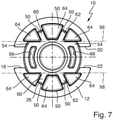
- figure 4 shows a section through the pump rotor 10 through the plane IV according to FIG figure 3 , whereby figure 7 a side view of the pump rotor 10 looking at the second bearing point 26 in the direction of the in figure 3 arrow 48 shown.
- the second bearing point 26 has bearing sections 50 which are spaced apart from one another and lie on a circular path arranged concentrically with respect to the axis of rotation 14 .
- the second bearing point 26 is while, as in figure 3 is clearly visible, cylindrical. If the pump rotor 10 now rotates in the direction of the arrow 52 during operation, an envelope of the second bearing point 26 is formed, which is circular-cylindrical.
- the second bearing point 26 has two radially opposite circular arc sections 54 which each have a bearing section 50 radially on the outside.
- the circular arc sections 54 are delimited by two planes 56, 58 arranged parallel to the blade shaft 18 and by the bearing sections 50 arranged concentrically to the circular path.
- the circular arc sections 54 are shown in FIG figure 7 clearly visible.
- Two web sections 60, 62 are arranged between the circular arc sections 54 and also have a bearing section 50 at their free end.
- a further radial guidance of the second bearing point 26 can be made possible in addition to the bearing sections 50 of the circular arc sections 54 .
- the second bearing point 26 with the circular arc sections 54 and the web sections 60, 62 is consequently formed in a segmented manner, since the bearing sections 50 lying on the circular path are spaced apart from one another.
- This segmented design of the second bearing point 26 has proven to be particularly advantageous since recesses 64 can be arranged in the base body 12 between the circular arc sections 54 and the web sections 60, 62.
- the recesses 64 extend as in section according to FIG figure 4 is clearly recognizable, almost up to the shaft shoulder 28 in the area of the first bearing point 24 and are designed almost cylindrically, with draft angles not visible in the figures being provided, which enable the molding of an injection mold.
- recesses 66 are also arranged in the circular arc sections 54 of the second bearing point 26 , but these extend only through the first bearing point 26 .
- the base body 12 can be injection molded with largely constant wall thicknesses and the formation of cavities can be largely or almost largely avoided.
- the pump rotor 10 has a blind hole 68 arranged concentrically to the axis of rotation 14, which opens into the first bearing point 24 on the front side and is fluidically connected to the vane shaft 18 in such a way that an oil supply is provided for lubricating a pump vane that can be arranged slidably in the vane shaft 18 can be.
Landscapes
- Engineering & Computer Science (AREA)
- Mechanical Engineering (AREA)
- General Engineering & Computer Science (AREA)
- Rotary Pumps (AREA)
- Applications Or Details Of Rotary Compressors (AREA)
Description
- Die Erfindung betrifft einen Rotor für eine Flügelzellenpumpe, insbesondere für eine Vakuumpumpe, mit einem drehantreibbaren Grundkörper aus einem Kunststoff, der im Betrieb um eine Drehachse rotiert, wobei der Grundkörper einen Führungsabschnitt zur gleitbeweglichen Aufnahme eines Pumpenflügels aufweist und wobei der Grundkörper in Richtung der Drehachse von einer ersten Lagerstelle und einer zweiten Lagerstelle flankiert wird. Die Erfindung betrifft ferner eine Flügelzellenpumpe, insbesondere eine Vakuumpumpe umfassend einen derartigen Rotor.
- Rotoren für Flügelzellenpumpen sind aus dem Stand der Technik vielfach bekannt. Derartige Rotoren weisen üblicherweise einen kreiszylindrischen Führungsabschnitt mit wenigstens einem Flügelschacht zur gleitenden Aufnahme eines Pumpenflügels auf, wobei auf beiden Seiten des Führungsabschnitts jeweils kreiszylindrische Lagerstellen vorgesehen sind, die in entsprechend damit korrespondierenden Lageraussparungen eines Pumpengehäuses aufgenommen sind, so dass der Rotor im Pumpengehäuse drehbar gelagert ist. Im Bereich des Führungsabschnitts weisen derartige Rotoren einen größeren Außendurchmesser als im Bereich der Lagerstellen auf, so dass zwischen dem Führungsabschnitt und den Lagerstellen ein Wellenabsatz vorgesehen ist, der auch als Anschlag in den Lageraussparungen des Pumpengehäuses dienen kann. Ein derartiger Rotor ist beispielsweise auch aus der
DE 10 2012 210 048 A1 bekannt. - Rotoren für Flügelzellenpumpen werden oftmals aus Metall hergestellt, wobei diese Rotoren mit verlorenen Formen gegossen werden. Darüber hinaus ist es jedoch auch bekannt, Rotoren für Flügelzellenpumpen im Kunststoffspritzgussverfahren herzustellen. Bei diesen aus Kunststoff hergestellten Rotoren hat sich jedoch gezeigt, dass eine massive Ausführung der Grundkörper der Rotoren zur Bildung von Lunkern führen kann. Um die Bildung von Lunkern zu vermeiden, ist es aus dem Stand der Technik bekannt, Aussparungen im Grundkörper in dem kreisringartigen Wellenabsatz des Führungsabschnitts vorzusehen, der einen größeren Durchmesser als die Lagerstellen aufweist. Derartige Aussparungen lassen sich jedoch nur bei vergleichsweise kurzen Rotoren mit einem vergleichsweise großen Durchmesser bzw. einem vergleichsweise großen Wellenabsatz realisieren. Bei vergleichsweise langen Rotoren mit einem vergleichsweise geringen Durchmesser ist diese Vorgehensweise jedoch problematisch, da die Unterschiede der Durchmesser von Führungsabschnitt und Lagerstellen zur Ausbildung ausreichend großer Aussparungen nicht geeignet sind.
- Aus der
WO 2004/083604 A1 ist ein Rotor mit Merkmalen des Oberbegriffs des Patentanspruchs 1 bekannt. Weitere Rotoren sind aus derWO 2012/056295A2 und derUS 4 384 828 A bekannt. - Die Erfindung stellt sich die Aufgabe, einen Kunststoffrotor für eine Flügelzellenpumpe, insbesondere für eine Vakuumpumpe bereitzustellen, bei dem die Bildung von Lunkern einfach und zuverlässig verhindert werden kann. Diese Aufgabe wird durch einen Rotor für eine Flügelzellenpumpe mit den Merkmalen des Anspruchs 1 gelöst. Der Rotor zeichnet sich dadurch aus, dass die zweite Lagerstelle auf einer konzentrisch zur Drehachse angeordneten Kreisbahn liegende, voneinander beabstandete Lagerabschnitte aufweist. Diese segmentierte Ausbildung der zweiten Lagerstelle hat sich als besonders vorteilhaft erwiesen, da eine Anordnung von Aussparungen nicht nur im Bereich des kreisringartigen Wellenabsatzes ermöglicht werden kann.
- Die zweite Lagerstelle weist zwei einander radial gegenüberliegende Kreisbogenabschnitte auf, die radial außen jeweils einen Lagerabschnitt aufweisen. Besonders bevorzugt ist es dabei, wenn die Kreisbogenabschnitte jeweils von zwei parallel zum Flügelschacht des Führungsabschnitts angeordneten Ebenen und die auf der konzentrisch zur Kreisbahn angeordneten Lagerabschnitte begrenzt werden.
- Zudem weist die zweite Lagerstelle zwischen den Kreisbogenabschnitten jeweils wenigstens einen, vorzugsweise zwei Stegabschnitte auf, die an ihrem freien Ende einen Lagerabschnitt aufweisen. Durch Vorsehen von zwischen den Kreisbogenabschnitten angeordneten Stegabschnitten kann zusätzlich zu den Lagerabschnitten der Kreisbogenabschnitte eine weitere radiale Führung der zweiten Lagerstelle ermöglicht werden, wobei zwischen den Stegen größere Aussparungen vorgesehen werden können.
- Besonders bevorzugt ist es daher, wenn der Grundkörper von der zweiten Lagerstelle ausgehende, sich entlang der Drehachse erstreckende Aussparungen aufweist. Vorteilhafterweise sind die Aussparungen zylindrisch oder nahezu zylindrisch derart ausgebildet, dass ein Spritzgusswerkzeug einfach ausgeformt werden kann. Als besonders vorteilhaft hat es sich ferner erwiesen, wenn die Aussparungen sich radial bis in die zweite Lagerstelle hinein erstrecken. Wie üblich weist der Grundkörper des Rotors im Bereich des Führungsabschnitts einen Flügelschacht auf, in dem ein Flügel zwischen zwei Ebenen gleitbeweglich aufnehmbar ist, wobei der Führungsabschnitt vorzugsweise kreiszylindrisch ausgebildet ist.
- In einer weiteren vorteilhaften Weiterbildung des Rotors ist vorgesehen, dass die zweite Lagerstelle zylindrisch ausgebildet ist. Da die Lagerabschnitte auf einer Kreisbahn angeordnet sind, ist eine Umhüllende der zweiten Lagerstelle im Betrieb des Rotors, d.h. bei Drehung um die Drehachse kreiszylindrisch ausgebildet. Besonders bevorzugt ist es ferner, wenn die die erste Lagerstelle kreiszylindrisch ausgebildet ist. Somit können die erste und die zweite Lagerstelle zur Lagerung des Rotors in kreiszylindrischen Ausnehmungen eines Pumpengehäuses aufgenommen werden.
- Eine weitere vorteilhafte Ausgestaltung des Rotors sieht vor, dass der Rotor eine konzentrisch zur Drehachse angeordnete Bohrung aufweist, die stirnseitig in die erste Lagerstelle mündet und dass der Führungsabschnitt einen Flügelschacht aufweist, wobei die Bohrung fluidisch mit dem Flügelschacht verbunden ist. Durch Vorsehen einer konzentrisch zur Drehachse angeordneten Bohrung, die fluidisch mit dem Flügelschacht verbunden ist, kann eine Ölversorgung zur Schmierung eines Pumpenflügels bereitgestellt werden.
- Eine besonders vorteilhafte Weiterbildung des Rotors sieht vor, dass in den Grundkörper im Bereich der ersten Lagerstelle ein metallisches Einlegeteil, das einen Drehmomentübertragungsabschnitt aufweist, formschlüssig eingesetzt ist. Besonders bevorzugt ist es dabei, wenn das Einlegeteil vom Kunststoff des Grundkörpers umspritzt ist. Durch Vorsehen des Einlegeteils mit dem Drehmomentübertragungsabschnitt kann eine Drehbewegung eines Antriebsaggregates wie bspw. eines Riementriebes oder eines Elektromotors auf den Pumpenrotor übertragen werden.
- Um eine Drehbewegung zuverlässig auf den Pumpenrotor zu übertragen ist es besonders bevorzugt, wenn das Einlegeteil konzentrisch zur Drehachse angeordnet ist.
- Zur formschlüssigen Verbindung des Einlegeteils und des Grundkörpers ist es vorteilhaft, wenn das Einlegeteil zylindrisch ausgebildet ist und auf seiner Mantelseite eine Verzahnung aufweist. Besonders bevorzugt ist es ferner, wenn der Grundkörper eine mit der Verzahnung korrespondierende Gegenverzahnung aufweist. Vorteilhafterweise ist diese Gegenverzahnung des Grundkörpers durch Umspritzen des Einlegeteils hergestellt.
- In einer besonders vorteilhaften Ausführungsform des Rotors ist die Verzahnung schwalbenschwanzartig derart ausgebildet, dass die Zähne der Verzahnung sich nach radial außen aufweiten. Diese schwalbenschwanzartige Aufweitung der Zähne der Verzahnung ist vorteilhaft, da im Betrieb des Pumpenrotors ein Aufspreizen des aus Kunststoff hergestellten Grundkörpers vermieden werden kann. Vielmehr kann der Grundkörper auf das metallische Einlegeteil gezogen werden.
- Als besonders vorteilhaft hat es sich erwiesen, wenn das Einlegeteil aus Sinterstahl, aus Stahl oder aus Messing hergestellt ist.
- Ferner ist es denkbar, dass der Drehmomentübertragungsabschnitt ein Innensechskant oder ein Zweiflach ist. Es ist jedoch auch denkbar, andere Möglichkeiten der Drehmomentübertragung oder andere Querschnitte zu verwenden.
- Die eingangs genannte Aufgabe wird auch gelöst durch eine Flügelzellenpumpe, insbesondere eine Vakuumpumpe, mit den Merkmalen des Anspruchs 13.
- Weitere Einzelheiten und vorteilhafte Weiterbildungen der Erfindung sind der nachfolgenden Beschreibung zu entnehmen, anhand derer die in den Figuren dargestellte Ausführungsform näher beschrieben und erläutert ist.
- Es zeigen:
-
Figur 1 eine Schrägansicht auf einen erfindungsgemäßen Pumpenrotor bei Blick auf eine erste Lagerstelle; -
Figur 2 eine Schrägansicht auf den Pumpenrotor gemäßFigur 1 in einer Explosionsdarstellung; -
Figur 3 eine Schrägansicht auf den Pumpenrotor gemäßFigur 1 und 2 bei Blick auf eine zweite Lagerstelle; -
Figur 4 einen Schnitt durch den Pumpenrotor gemäß derFiguren 1 bis 3 durch die Ebene IV gemäßFigur 3 ; -
Figur 5 einen Schnitt durch den Pumpenrotor gemäß derFiguren 1 bis 3 senkrecht zur Drehachse; -
Figur 6 eine Detailansicht VI des Schnitts durch den Pumpenrotor gemäßFigur 5 ; und -
Figur 7 eine Seitenansicht des Pumpenrotors gemäß derFiguren 1 bis 3 bei Blick auf die zweite Lagerstelle. -
Figur 1 zeigt einen Pumpenrotor 10 für eine in den Figuren nicht dargestellte Flügelzellenpumpe, insbesondere für eine Vakuumpumpe. In den Figuren sind sich entsprechende Bauteile und Elemente mit den entsprechenden Bezugszeichen gekennzeichnet. Der Pumpenrotor 10 weist einen Grundkörper 12 aus einem Kunststoff auf, der im Betrieb um eine Drehachse 14 rotiert. Der Grundkörper 12 weist einen Führungsabschnitt 16 mit einem Flügelschacht 18 zur gleitbeweglichen Aufnahme eines Pumpenflügels auf. Der Flügelschacht 18 wird dabei von zwei parallelen Ebenen 20, 22 begrenzt, die eine Führung für den Pumpenflügel bereitstellen. - In Richtung der Drehachse 14 wird der Führungsabschnitt 16 von einer ersten Lagerstelle 24 und einer zweiten Lagerstelle 26 flankiert, wobei der Führungsabschnitt 16 einen größeren Durchmesser als die erste Lagerstelle 24 aufweist, so dass zwischen der ersten Lagerstelle 24 und dem Führungsabschnitt 16 ein Wellenabsatz 28 angeordnet ist. Die erste Lagerstelle 24 ist kreiszylindrisch ausgebildet. Die erste Lagerstelle 24 und die zweite Lagerstelle 26 sind derart ausgebildet, dass sie in kreiszylindrischen Lageraufnahmen eines nicht dargestellten Pumpengehäuses aufgenommen werden können.
- Der Grundkörper 12 ist drehantreibbar und weist hierzu im Bereich der ersten Lagerstelle 24 ein metallisches Einlegeteil 30 aus einem Sintermetall oder Messing auf, das konzentrisch zur Drehachse 14 angeordnet ist. Das metallische Einlegeteil 30 ist in der Explosionsdarstellung gemäß
Figur 2 deutlich zu erkennen. Das Einlegeteil 30 weist einen Drehmomentübertragungsabschnitt 32 in Form eines Sechskants auf, der inFigur 5 und 6 deutlich zu erkennen ist. Durch Vorsehen des Drehmomentübertragungsabschnitts 32 kann eine Drehbewegung eines Antriebsaggregates wie bspw. eines Riemenantriebes oder eines Elektromotors auf den Pumpenrotor 10 übertragen werden. - Zur Drehmomentübertragung vom Einlegeteil 30 auf den Grundkörper 12 ist das Einlegeteil 30 formschlüssig in den Grundkörper 12 eingesetzt. Insbesondere ist das Einlegeteil 30 vom Kunststoff des Grundkörpers umspritzt. Das Einlegeteil 30 weist zur Drehmomentübertragung auf den Grundkörper 12 auf seiner Mantelseite 34 eine in den
Figuren 3 ,5 und 6 deutlich erkennbare Verzahnung 36 auf. - Durch das Umspritzen des Einlegeteils 30 weist der Grundkörper 12 eine mit der Verzahnung 36 korrespondierende Gegenverzahnung 38 auf, die ebenfalls in den
Figuren 3 ,5 und 6 deutlich zu erkennen ist.Figur 5 zeigt dabei einen Schnitt durch den Pumpenrotor 10 in einer Ebene senkrecht zur Drehachse 14 des Pumpenrotors 10, wobeiFigur 6 eine Detailansicht VI des Schnitts gemäßFigur 5 zeigt. - Die Verzahnung 36 des Einlegeteils 30 ist schwalbenschwanzartig ausgebildet und weist eine Vielzahl von Zähnen 40 auf. Insbesondere ist die Verzahnung 36 schwalbenschwanzartig derart ausgebildet, dass die Zähne 40 der Verzahnung 36 sich nach radial außen, d.h. senkrecht zur Drehachse 14 aufweiten. Die Flanken 42 der Zähne 40 schließen dabei mit einer Zahnmittelebene 44 einen Winkel 46 ein. Diese schwalbenschwanzartige Aufweitung der Zähne 40 ist vorteilhaft, da im Betrieb des Pumpenrotors 10 ein Aufspreizen des aus Kunststoff hergestellten Grundkörpers 12 vermieden werden kann.
-
Figur 3 zeigt eine Schrägansicht auf den Pumpenrotor 10 gemäß derFiguren 1 und 2 bei Blick auf eine zweite Lagerstelle 26. -
Figur 4 zeigt einen Schnitt durch den Pumpenrotor 10 durch die Ebene IV gemäßFigur 3 , wobeiFigur 7 eine Seitenansicht des Pumpenrotors 10 bei Blick auf die zweite Lagerstelle 26 in Richtung des inFigur 3 gezeigten Pfeils 48 zeigt. - Wie in
Figur 7 deutlich zu erkennen ist, weist die zweite Lagerstelle 26 auf einer konzentrisch zur Drehachse 14 angeordneten Kreisbahn liegende, voneinander beabstandete Lagerabschnitte 50 auf. Die zweite Lagerstelle 26 ist dabei, wie inFigur 3 deutlich erkennbar ist, zylindrisch ausgebildet. Wenn nun der Pumpenrotor 10 im Betrieb in Richtung des Pfeils 52 rotiert, wird eine Umhüllende der zweiten Lagerstelle 26 gebildet, die kreiszylindrisch ausgebildet ist. - Die zweite Lagerstelle 26 weist zwei einander radial gegenüberliegende Kreisbogenabschnitte 54 auf, die radial außen jeweils einen Lagerabschnitt 50 aufweisen. Die Kreisbogenabschnitte 54 werden von zwei parallel zum Flügelschacht 18 angeordneten Ebenen 56, 58 und die auf der konzentrisch zur Kreisbahn angeordneten Lagerabschnitte 50 begrenzt. Die Kreisbogenabschnitte 54 sind in der Ansicht gemäß
Figur 7 deutlich zu erkennen. - Zwischen den Kreisbogenabschnitten 54 sind jeweils zwei Stegabschnitte 60, 62 angeordnet, die an ihrem freien Ende ebenfalls einen Lagerabschnitt 50 aufweisen. Durch Vorsehen der zwischen den Kreisbogenabschnitten 54 angeordneten Stegabschnitte 60, 62 kann zusätzlich zu den Lagerabschnitten 50 der Kreisbogenabschnitte 54 eine weitere radiale Führung der zweiten Lagerstelle 26 ermöglicht werden.
- Die zweite Lagerstelle 26 mit den Kreisbogenabschnitten 54 und den Stegabschnitten 60, 62 ist folglich segmentiert ausgebildet, da die auf der Kreisbahn liegenden Lagerabschnitte 50 voneinander beabstandet sind. Diese segmentierte Ausbildung der zweiten Lagerstelle 26 hat sich als besonders vorteilhaft erwiesen, da zwischen den Kreisbogenabschnitten 54 und den Stegabschnitten 60, 62 Aussparungen 64 im Grundkörper 12 angeordnet werden können.
- Die Aussparungen 64 erstrecken sich dabei, wie im Schnitt gemäß
Figur 4 deutlich erkennbar ist, fast bis zum Wellenabsatz 28 im Bereich der ersten Lagerstelle 24 und sind nahezu zylindrisch ausgebildet, wobei in den Figuren nicht erkennbare Ausformschrägen vorgesehen sind, die ein Ausformen eines Spritzgießwerkzeugs ermöglichen. Zusätzlich zu den Aussparungen 64 sind in den Kreisbogenabschnitten 54 der zweiten Lagerstelle 26 noch Aussparungen 66 angeordnet, die sich jedoch nur durch die erste Lagerstelle 26 hindurch erstrecken. - Aufgrund der Aussparungen 64, 66 kann der Grundkörper 12 im Spritzgussverfahren mit weitgehend konstanten Wanddicken spritzgegossen werden und eine Bildung von Lunkern weitgehend oder nahezu weitgehend vermieden werden.
- Wie im Schnitt gemäß
Figur 4 deutlich zu erkennen ist, weist der Pumpenrotor 10 eine konzentrisch zur Drehachse 14 angeordnete Sacklochbohrung 68 auf, die stirnseitig in die erste Lagerstelle 24 mündet und mit dem Flügelschacht 18 fluidisch derart verbunden ist, dass eine Ölversorgung zur Schmierung eines im Flügelschacht 18 gleitbeweglich anordenbaren Pumpenflügels bereitgestellt werden kann.
Claims (11)
- Rotor (10) für eine Flügelzellenpumpe, insbesondere für eine Vakuumpumpe, mit einem drehantreibbaren Grundkörper (12) aus einem Kunststoff, der im Betrieb um eine Drehachse (14) rotiert, wobei der Grundkörper (12) einen Führungsabschnitt (16) zur gleitbeweglichen Aufnahme eines Pumpenflügels aufweist und wobei der Grundkörper (12) in Richtung der Drehachse (14) von einer ersten Lagerstelle (24) und einer zweiten Lagerstelle (26) flankiert wird, wobei die zweite Lagerstelle (26) auf einer konzentrisch zur Drehachse (14) angeordneten Kreisbahn liegende, voneinander beabstandete Lagerabschnitte (50) aufweist, und wobei die zweite Lagerstelle (26) zwei einander radial gegenüberliegende Kreisbogenabschnitte (54) aufweist, die radial außen jeweils einen Lagerabschnitt (50) aufweisen, dadurch gekennzeichnet, dass die zweite Lagerstelle (26) zwischen den Kreisbogenabschnitten (54) jeweils wenigstens einen, vorzugsweise zwei Stegabschnitte (60, 62) aufweist, die an ihrem freien Ende einen Lagerabschnitt (50) aufweisen.
- Rotor (10) nach Anspruch 1, dadurch gekennzeichnet, dass der Grundkörper (12) von der zweiten Lagerstelle (26) ausgehende, sich entlang der Drehachse (14) erstreckende Aussparungen (64, 66) aufweist.
- Rotor (10) nach wenigstens einem der vorhergehenden Ansprüche, dadurch gekennzeichnet, dass die zweite Lagerstelle (26) zylindrisch ausgebildet ist.
- Rotor (10) nach wenigstens einem der vorhergehenden Ansprüche, dadurch gekennzeichnet, dass der Rotor (10) eine konzentrisch zur Drehachse (14) angeordnete Bohrung (68) aufweist, die stirnseitig in die erste Lagerstelle (24) mündet und dass der Führungsabschnitt (16) einen Flügelschacht (18) aufweist, wobei die Bohrung (68) fluidisch mit dem Flügelschacht (18) verbunden ist.
- Rotor (10) nach wenigstens einem der vorhergehenden Ansprüche, dadurch gekennzeichnet, dass in den Grundkörper (12) im Bereich der ersten Lagerstelle (24) ein metallisches Einlegeteil (30), das einen Drehmomentübertragungsabschnitt (32) aufweist, formschlüssig eingesetzt ist.
- Rotor(10) nach Anspruch 5, dadurch gekennzeichnet, dass das Einlegeteil (30) konzentrisch zur Drehachse (14) angeordnet ist.
- Rotor (10) nach Anspruch 5 oder 6, dadurch gekennzeichnet, dass das Einlegeteil (30) zylindrisch ausgebildet ist und auf seiner Mantelseite (34) eine Verzahnung (36) aufweist.
- Rotor (10) nach Anspruch 7, dadurch gekennzeichnet, dass die Verzahnung (36) schwalbenschwanzartig derart ausgebildet ist, dass die Zähne (40) der Verzahnung (36) sich nach radial außen aufweiten.
- Rotor (10) nach wenigstens einem der Ansprüche 5 bis 8, dadurch gekennzeichnet, dass das Einlegeteil (30) aus Sinterstahl, aus Stahl oder aus Messing hergestellt ist.
- Rotor (10) nach wenigstens einem der Ansprüche 5 bis 9, dadurch gekennzeichnet, dass der Drehmomentübertragungsabschnitt (32) ein Innensechskant oder ein Zweiflach ist.
- Flügelzellenpumpe, insbesondere Vakuumpumpe, umfassend einen Rotor (10) nach wenigstens einem der vorhergehenden Ansprüche.
Applications Claiming Priority (1)
| Application Number | Priority Date | Filing Date | Title |
|---|---|---|---|
| DE102015213099.1A DE102015213099B3 (de) | 2015-07-13 | 2015-07-13 | Kunststoffrotor für Vakuumpumpe |
Publications (2)
| Publication Number | Publication Date |
|---|---|
| EP3118456A1 EP3118456A1 (de) | 2017-01-18 |
| EP3118456B1 true EP3118456B1 (de) | 2022-02-23 |
Family
ID=56116313
Family Applications (1)
| Application Number | Title | Priority Date | Filing Date |
|---|---|---|---|
| EP16173480.1A Active EP3118456B1 (de) | 2015-07-13 | 2016-06-08 | Kunststoffrotor für vakuumpumpe |
Country Status (4)
| Country | Link |
|---|---|
| US (1) | US10138888B2 (de) |
| EP (1) | EP3118456B1 (de) |
| CN (1) | CN106351838B (de) |
| DE (1) | DE102015213099B3 (de) |
Families Citing this family (1)
| Publication number | Priority date | Publication date | Assignee | Title |
|---|---|---|---|---|
| CN107313940B (zh) * | 2017-07-28 | 2019-10-08 | 威伯科汽车控制系统(中国)有限公司 | 一种壳体及真空泵 |
Family Cites Families (9)
| Publication number | Priority date | Publication date | Assignee | Title |
|---|---|---|---|---|
| DE2938276A1 (de) * | 1979-09-21 | 1981-04-09 | Robert Bosch Gmbh, 7000 Stuttgart | Fluegelzellenverdichter |
| DE3150569A1 (de) * | 1981-12-21 | 1983-06-30 | Barmag Barmer Maschinenfabrik Ag, 5630 Remscheid | Fluegelzellenpumpe |
| KR19990072320A (ko) * | 1998-02-02 | 1999-09-27 | 나카무라 시게오 | 베인-타입유체기계 |
| DE10247668B4 (de) * | 2001-10-15 | 2013-03-07 | Ixetic Hückeswagen Gmbh | Vakuumpumpe |
| WO2004083604A1 (de) * | 2003-03-21 | 2004-09-30 | Luk Automobiltechnik Gmbh & Co. Kg | Pumpenrotor |
| EP2150702A1 (de) * | 2007-04-10 | 2010-02-10 | BorgWarner Inc. | Verstellbare doppelflügelzellenpumpe |
| DE102008054240A1 (de) * | 2007-11-13 | 2009-07-30 | Ixetic Hückeswagen Gmbh | Rotor für eine Pumpe |
| IT1402417B1 (it) * | 2010-10-26 | 2013-09-04 | O M P Officine Mazzocco Pagnoni S R L | Pompa monopaletta |
| DE102012210048A1 (de) * | 2012-06-14 | 2013-12-19 | Joma-Polytec Gmbh | Verdrängerpumpe |
-
2015
- 2015-07-13 DE DE102015213099.1A patent/DE102015213099B3/de active Active
-
2016
- 2016-06-08 EP EP16173480.1A patent/EP3118456B1/de active Active
- 2016-07-12 CN CN201610547691.6A patent/CN106351838B/zh active Active
- 2016-07-12 US US15/207,887 patent/US10138888B2/en active Active
Also Published As
| Publication number | Publication date |
|---|---|
| CN106351838A (zh) | 2017-01-25 |
| EP3118456A1 (de) | 2017-01-18 |
| US10138888B2 (en) | 2018-11-27 |
| US20170016445A1 (en) | 2017-01-19 |
| DE102015213099B3 (de) | 2016-08-04 |
| CN106351838B (zh) | 2019-02-19 |
Similar Documents
| Publication | Publication Date | Title |
|---|---|---|
| EP3218663B1 (de) | Rotationswärmetauschereinrichtung | |
| EP2626567B2 (de) | Pumpengehäuse | |
| DE19613833A1 (de) | Innenzahnradmaschine, insbesondere Innenzahnradpumpe | |
| DE102012222602A1 (de) | Elektrische Maschine | |
| DE102008006289B4 (de) | Pumpenrad | |
| DE112016003059B4 (de) | Gewindetrieb | |
| EP2504579A2 (de) | Flügelzellenpumpe | |
| DE102004034921B9 (de) | Einflügelvakuumpumpe | |
| EP2746532B1 (de) | Rotoranordnung für eine Vakuumpumpe sowie Vakuumpumpe mit einer derartigen Rotoranordnung | |
| DE102015213099B3 (de) | Kunststoffrotor für Vakuumpumpe | |
| DE102012205687A1 (de) | Mehrteiliger Stator für eine elektrische Maschine, elektrische Maschine | |
| DE102012104804A1 (de) | Verdrängerpumpe | |
| DE102008015694A1 (de) | Differentialgetriebe mit einer Schmierungsstruktur | |
| WO2018108203A1 (de) | Welle-nabe-verbindung mit einem zentrierbereich und (p2-)hybridfahrzeugantriebsstrang | |
| EP2994645B1 (de) | Magnetpumpenanordnung | |
| DE102015209833B4 (de) | Zahnradmaschine | |
| EP2999906B1 (de) | Gleitringdichtung mit verbesserter drehmomentübertragung | |
| EP2424083B1 (de) | Elektromotor und Verfahren zu dessen Herstellung | |
| DE102013202606A1 (de) | Zahnradmaschine mit einer Lagerhülse, die mehrere Vorsprünge aufweist. | |
| EP3032105A1 (de) | Mechanische kfz-vakuumpumpe | |
| EP4031785B1 (de) | Axial montierbare gleitringdichtungsanordnung | |
| EP2626565B1 (de) | Spaltrohrmotor-Pumpe mit hohler Welle und Drosselstelle in der Welle | |
| DE102017201384A1 (de) | Freilauf und Starter | |
| DE202014106254U1 (de) | Arretiervorrichtung für eine Windenergieanlage | |
| DE102008024442A1 (de) | Vakuumpumpe |
Legal Events
| Date | Code | Title | Description |
|---|---|---|---|
| PUAI | Public reference made under article 153(3) epc to a published international application that has entered the european phase |
Free format text: ORIGINAL CODE: 0009012 |
|
| STAA | Information on the status of an ep patent application or granted ep patent |
Free format text: STATUS: THE APPLICATION HAS BEEN PUBLISHED |
|
| AK | Designated contracting states |
Kind code of ref document: A1 Designated state(s): AL AT BE BG CH CY CZ DE DK EE ES FI FR GB GR HR HU IE IS IT LI LT LU LV MC MK MT NL NO PL PT RO RS SE SI SK SM TR |
|
| AX | Request for extension of the european patent |
Extension state: BA ME |
|
| RIN1 | Information on inventor provided before grant (corrected) |
Inventor name: HESS, BERND Inventor name: GULDE, THOMAS Inventor name: PFITZER, FRIEDHEIM Inventor name: HELLE, TORSTEN Inventor name: THOMA, MARTIN Inventor name: OTT, HANS-PETER |
|
| STAA | Information on the status of an ep patent application or granted ep patent |
Free format text: STATUS: REQUEST FOR EXAMINATION WAS MADE |
|
| 17P | Request for examination filed |
Effective date: 20170710 |
|
| RBV | Designated contracting states (corrected) |
Designated state(s): AL AT BE BG CH CY CZ DE DK EE ES FI FR GB GR HR HU IE IS IT LI LT LU LV MC MK MT NL NO PL PT RO RS SE SI SK SM TR |
|
| STAA | Information on the status of an ep patent application or granted ep patent |
Free format text: STATUS: EXAMINATION IS IN PROGRESS |
|
| 17Q | First examination report despatched |
Effective date: 20200225 |
|
| GRAP | Despatch of communication of intention to grant a patent |
Free format text: ORIGINAL CODE: EPIDOSNIGR1 |
|
| STAA | Information on the status of an ep patent application or granted ep patent |
Free format text: STATUS: GRANT OF PATENT IS INTENDED |
|
| GRAJ | Information related to disapproval of communication of intention to grant by the applicant or resumption of examination proceedings by the epo deleted |
Free format text: ORIGINAL CODE: EPIDOSDIGR1 |
|
| GRAP | Despatch of communication of intention to grant a patent |
Free format text: ORIGINAL CODE: EPIDOSNIGR1 |
|
| INTG | Intention to grant announced |
Effective date: 20211012 |
|
| RIN1 | Information on inventor provided before grant (corrected) |
Inventor name: DIE WEITEREN ERFINDER HABEN AUF IHR RECHT VERZICHTET, ALS SOLCHE BEKANNT GEMACHT ZU WERDEN. Inventor name: HELLE, TORSTEN Inventor name: GULDE, THOMAS Inventor name: THOMA, MARTIN Inventor name: HESS, BERND Inventor name: OTT, HANS-PETER |
|
| INTG | Intention to grant announced |
Effective date: 20211026 |
|
| GRAS | Grant fee paid |
Free format text: ORIGINAL CODE: EPIDOSNIGR3 |
|
| GRAA | (expected) grant |
Free format text: ORIGINAL CODE: 0009210 |
|
| STAA | Information on the status of an ep patent application or granted ep patent |
Free format text: STATUS: THE PATENT HAS BEEN GRANTED |
|
| AK | Designated contracting states |
Kind code of ref document: B1 Designated state(s): AL AT BE BG CH CY CZ DE DK EE ES FI FR GB GR HR HU IE IS IT LI LT LU LV MC MK MT NL NO PL PT RO RS SE SI SK SM TR |
|
| REG | Reference to a national code |
Ref country code: GB Ref legal event code: FG4D Free format text: NOT ENGLISH |
|
| REG | Reference to a national code |
Ref country code: CH Ref legal event code: EP |
|
| REG | Reference to a national code |
Ref country code: AT Ref legal event code: REF Ref document number: 1470666 Country of ref document: AT Kind code of ref document: T Effective date: 20220315 |
|
| REG | Reference to a national code |
Ref country code: IE Ref legal event code: FG4D Free format text: LANGUAGE OF EP DOCUMENT: GERMAN |
|
| REG | Reference to a national code |
Ref country code: DE Ref legal event code: R096 Ref document number: 502016014538 Country of ref document: DE |
|
| REG | Reference to a national code |
Ref country code: LT Ref legal event code: MG9D |
|
| REG | Reference to a national code |
Ref country code: NL Ref legal event code: MP Effective date: 20220223 |
|
| PG25 | Lapsed in a contracting state [announced via postgrant information from national office to epo] |
Ref country code: SE Free format text: LAPSE BECAUSE OF FAILURE TO SUBMIT A TRANSLATION OF THE DESCRIPTION OR TO PAY THE FEE WITHIN THE PRESCRIBED TIME-LIMIT Effective date: 20220223 Ref country code: RS Free format text: LAPSE BECAUSE OF FAILURE TO SUBMIT A TRANSLATION OF THE DESCRIPTION OR TO PAY THE FEE WITHIN THE PRESCRIBED TIME-LIMIT Effective date: 20220223 Ref country code: PT Free format text: LAPSE BECAUSE OF FAILURE TO SUBMIT A TRANSLATION OF THE DESCRIPTION OR TO PAY THE FEE WITHIN THE PRESCRIBED TIME-LIMIT Effective date: 20220623 Ref country code: NO Free format text: LAPSE BECAUSE OF FAILURE TO SUBMIT A TRANSLATION OF THE DESCRIPTION OR TO PAY THE FEE WITHIN THE PRESCRIBED TIME-LIMIT Effective date: 20220523 Ref country code: NL Free format text: LAPSE BECAUSE OF FAILURE TO SUBMIT A TRANSLATION OF THE DESCRIPTION OR TO PAY THE FEE WITHIN THE PRESCRIBED TIME-LIMIT Effective date: 20220223 Ref country code: LT Free format text: LAPSE BECAUSE OF FAILURE TO SUBMIT A TRANSLATION OF THE DESCRIPTION OR TO PAY THE FEE WITHIN THE PRESCRIBED TIME-LIMIT Effective date: 20220223 Ref country code: HR Free format text: LAPSE BECAUSE OF FAILURE TO SUBMIT A TRANSLATION OF THE DESCRIPTION OR TO PAY THE FEE WITHIN THE PRESCRIBED TIME-LIMIT Effective date: 20220223 Ref country code: ES Free format text: LAPSE BECAUSE OF FAILURE TO SUBMIT A TRANSLATION OF THE DESCRIPTION OR TO PAY THE FEE WITHIN THE PRESCRIBED TIME-LIMIT Effective date: 20220223 Ref country code: BG Free format text: LAPSE BECAUSE OF FAILURE TO SUBMIT A TRANSLATION OF THE DESCRIPTION OR TO PAY THE FEE WITHIN THE PRESCRIBED TIME-LIMIT Effective date: 20220523 |
|
| PG25 | Lapsed in a contracting state [announced via postgrant information from national office to epo] |
Ref country code: PL Free format text: LAPSE BECAUSE OF FAILURE TO SUBMIT A TRANSLATION OF THE DESCRIPTION OR TO PAY THE FEE WITHIN THE PRESCRIBED TIME-LIMIT Effective date: 20220223 Ref country code: LV Free format text: LAPSE BECAUSE OF FAILURE TO SUBMIT A TRANSLATION OF THE DESCRIPTION OR TO PAY THE FEE WITHIN THE PRESCRIBED TIME-LIMIT Effective date: 20220223 Ref country code: FI Free format text: LAPSE BECAUSE OF FAILURE TO SUBMIT A TRANSLATION OF THE DESCRIPTION OR TO PAY THE FEE WITHIN THE PRESCRIBED TIME-LIMIT Effective date: 20220223 |
|
| PG25 | Lapsed in a contracting state [announced via postgrant information from national office to epo] |
Ref country code: IS Free format text: LAPSE BECAUSE OF FAILURE TO SUBMIT A TRANSLATION OF THE DESCRIPTION OR TO PAY THE FEE WITHIN THE PRESCRIBED TIME-LIMIT Effective date: 20220623 |
|
| PG25 | Lapsed in a contracting state [announced via postgrant information from national office to epo] |
Ref country code: SM Free format text: LAPSE BECAUSE OF FAILURE TO SUBMIT A TRANSLATION OF THE DESCRIPTION OR TO PAY THE FEE WITHIN THE PRESCRIBED TIME-LIMIT Effective date: 20220223 Ref country code: SK Free format text: LAPSE BECAUSE OF FAILURE TO SUBMIT A TRANSLATION OF THE DESCRIPTION OR TO PAY THE FEE WITHIN THE PRESCRIBED TIME-LIMIT Effective date: 20220223 Ref country code: RO Free format text: LAPSE BECAUSE OF FAILURE TO SUBMIT A TRANSLATION OF THE DESCRIPTION OR TO PAY THE FEE WITHIN THE PRESCRIBED TIME-LIMIT Effective date: 20220223 Ref country code: EE Free format text: LAPSE BECAUSE OF FAILURE TO SUBMIT A TRANSLATION OF THE DESCRIPTION OR TO PAY THE FEE WITHIN THE PRESCRIBED TIME-LIMIT Effective date: 20220223 Ref country code: DK Free format text: LAPSE BECAUSE OF FAILURE TO SUBMIT A TRANSLATION OF THE DESCRIPTION OR TO PAY THE FEE WITHIN THE PRESCRIBED TIME-LIMIT Effective date: 20220223 Ref country code: CZ Free format text: LAPSE BECAUSE OF FAILURE TO SUBMIT A TRANSLATION OF THE DESCRIPTION OR TO PAY THE FEE WITHIN THE PRESCRIBED TIME-LIMIT Effective date: 20220223 |
|
| REG | Reference to a national code |
Ref country code: DE Ref legal event code: R097 Ref document number: 502016014538 Country of ref document: DE |
|
| PG25 | Lapsed in a contracting state [announced via postgrant information from national office to epo] |
Ref country code: AL Free format text: LAPSE BECAUSE OF FAILURE TO SUBMIT A TRANSLATION OF THE DESCRIPTION OR TO PAY THE FEE WITHIN THE PRESCRIBED TIME-LIMIT Effective date: 20220223 |
|
| PLBE | No opposition filed within time limit |
Free format text: ORIGINAL CODE: 0009261 |
|
| STAA | Information on the status of an ep patent application or granted ep patent |
Free format text: STATUS: NO OPPOSITION FILED WITHIN TIME LIMIT |
|
| PG25 | Lapsed in a contracting state [announced via postgrant information from national office to epo] |
Ref country code: MC Free format text: LAPSE BECAUSE OF FAILURE TO SUBMIT A TRANSLATION OF THE DESCRIPTION OR TO PAY THE FEE WITHIN THE PRESCRIBED TIME-LIMIT Effective date: 20220223 |
|
| REG | Reference to a national code |
Ref country code: CH Ref legal event code: PL |
|
| 26N | No opposition filed |
Effective date: 20221124 |
|
| REG | Reference to a national code |
Ref country code: BE Ref legal event code: MM Effective date: 20220630 |
|
| PG25 | Lapsed in a contracting state [announced via postgrant information from national office to epo] |
Ref country code: SI Free format text: LAPSE BECAUSE OF FAILURE TO SUBMIT A TRANSLATION OF THE DESCRIPTION OR TO PAY THE FEE WITHIN THE PRESCRIBED TIME-LIMIT Effective date: 20220223 |
|
| GBPC | Gb: european patent ceased through non-payment of renewal fee |
Effective date: 20220608 |
|
| PG25 | Lapsed in a contracting state [announced via postgrant information from national office to epo] |
Ref country code: LU Free format text: LAPSE BECAUSE OF NON-PAYMENT OF DUE FEES Effective date: 20220608 Ref country code: LI Free format text: LAPSE BECAUSE OF NON-PAYMENT OF DUE FEES Effective date: 20220630 Ref country code: IE Free format text: LAPSE BECAUSE OF NON-PAYMENT OF DUE FEES Effective date: 20220608 Ref country code: FR Free format text: LAPSE BECAUSE OF NON-PAYMENT OF DUE FEES Effective date: 20220630 Ref country code: CH Free format text: LAPSE BECAUSE OF NON-PAYMENT OF DUE FEES Effective date: 20220630 |
|
| PG25 | Lapsed in a contracting state [announced via postgrant information from national office to epo] |
Ref country code: GB Free format text: LAPSE BECAUSE OF NON-PAYMENT OF DUE FEES Effective date: 20220608 Ref country code: BE Free format text: LAPSE BECAUSE OF NON-PAYMENT OF DUE FEES Effective date: 20220630 |
|
| P01 | Opt-out of the competence of the unified patent court (upc) registered |
Effective date: 20230620 |
|
| PG25 | Lapsed in a contracting state [announced via postgrant information from national office to epo] |
Ref country code: IT Free format text: LAPSE BECAUSE OF FAILURE TO SUBMIT A TRANSLATION OF THE DESCRIPTION OR TO PAY THE FEE WITHIN THE PRESCRIBED TIME-LIMIT Effective date: 20220223 |
|
| REG | Reference to a national code |
Ref country code: AT Ref legal event code: MM01 Ref document number: 1470666 Country of ref document: AT Kind code of ref document: T Effective date: 20220608 |
|
| PG25 | Lapsed in a contracting state [announced via postgrant information from national office to epo] |
Ref country code: AT Free format text: LAPSE BECAUSE OF NON-PAYMENT OF DUE FEES Effective date: 20220608 |
|
| PG25 | Lapsed in a contracting state [announced via postgrant information from national office to epo] |
Ref country code: HU Free format text: LAPSE BECAUSE OF FAILURE TO SUBMIT A TRANSLATION OF THE DESCRIPTION OR TO PAY THE FEE WITHIN THE PRESCRIBED TIME-LIMIT; INVALID AB INITIO Effective date: 20160608 |
|
| PG25 | Lapsed in a contracting state [announced via postgrant information from national office to epo] |
Ref country code: MK Free format text: LAPSE BECAUSE OF FAILURE TO SUBMIT A TRANSLATION OF THE DESCRIPTION OR TO PAY THE FEE WITHIN THE PRESCRIBED TIME-LIMIT Effective date: 20220223 Ref country code: CY Free format text: LAPSE BECAUSE OF FAILURE TO SUBMIT A TRANSLATION OF THE DESCRIPTION OR TO PAY THE FEE WITHIN THE PRESCRIBED TIME-LIMIT Effective date: 20220223 |
|
| PG25 | Lapsed in a contracting state [announced via postgrant information from national office to epo] |
Ref country code: MT Free format text: LAPSE BECAUSE OF FAILURE TO SUBMIT A TRANSLATION OF THE DESCRIPTION OR TO PAY THE FEE WITHIN THE PRESCRIBED TIME-LIMIT Effective date: 20220223 |
|
| PG25 | Lapsed in a contracting state [announced via postgrant information from national office to epo] |
Ref country code: GR Free format text: LAPSE BECAUSE OF NON-PAYMENT OF DUE FEES Effective date: 20220223 |
|
| PG25 | Lapsed in a contracting state [announced via postgrant information from national office to epo] |
Ref country code: GR Free format text: LAPSE BECAUSE OF NON-PAYMENT OF DUE FEES Effective date: 20220223 |
|
| PGFP | Annual fee paid to national office [announced via postgrant information from national office to epo] |
Ref country code: DE Payment date: 20250815 Year of fee payment: 10 |
|
| PG25 | Lapsed in a contracting state [announced via postgrant information from national office to epo] |
Ref country code: TR Free format text: LAPSE BECAUSE OF FAILURE TO SUBMIT A TRANSLATION OF THE DESCRIPTION OR TO PAY THE FEE WITHIN THE PRESCRIBED TIME-LIMIT Effective date: 20220223 |