EP3118259A1 - Electrical insulation material and mold electric apparatus - Google Patents
Electrical insulation material and mold electric apparatus Download PDFInfo
- Publication number
- EP3118259A1 EP3118259A1 EP15761064.3A EP15761064A EP3118259A1 EP 3118259 A1 EP3118259 A1 EP 3118259A1 EP 15761064 A EP15761064 A EP 15761064A EP 3118259 A1 EP3118259 A1 EP 3118259A1
- Authority
- EP
- European Patent Office
- Prior art keywords
- electrical
- insulating material
- molded
- magnesia
- expansion coefficient
- Prior art date
- Legal status (The legal status is an assumption and is not a legal conclusion. Google has not performed a legal analysis and makes no representation as to the accuracy of the status listed.)
- Withdrawn
Links
Images


Classifications
-
- C—CHEMISTRY; METALLURGY
- C08—ORGANIC MACROMOLECULAR COMPOUNDS; THEIR PREPARATION OR CHEMICAL WORKING-UP; COMPOSITIONS BASED THEREON
- C08L—COMPOSITIONS OF MACROMOLECULAR COMPOUNDS
- C08L63/00—Compositions of epoxy resins; Compositions of derivatives of epoxy resins
-
- C—CHEMISTRY; METALLURGY
- C08—ORGANIC MACROMOLECULAR COMPOUNDS; THEIR PREPARATION OR CHEMICAL WORKING-UP; COMPOSITIONS BASED THEREON
- C08K—Use of inorganic or non-macromolecular organic substances as compounding ingredients
- C08K3/00—Use of inorganic substances as compounding ingredients
- C08K3/18—Oxygen-containing compounds, e.g. metal carbonyls
- C08K3/20—Oxides; Hydroxides
- C08K3/22—Oxides; Hydroxides of metals
-
- C—CHEMISTRY; METALLURGY
- C08—ORGANIC MACROMOLECULAR COMPOUNDS; THEIR PREPARATION OR CHEMICAL WORKING-UP; COMPOSITIONS BASED THEREON
- C08K—Use of inorganic or non-macromolecular organic substances as compounding ingredients
- C08K3/00—Use of inorganic substances as compounding ingredients
- C08K3/34—Silicon-containing compounds
- C08K3/36—Silica
-
- H—ELECTRICITY
- H01—ELECTRIC ELEMENTS
- H01B—CABLES; CONDUCTORS; INSULATORS; SELECTION OF MATERIALS FOR THEIR CONDUCTIVE, INSULATING OR DIELECTRIC PROPERTIES
- H01B3/00—Insulators or insulating bodies characterised by the insulating materials; Selection of materials for their insulating or dielectric properties
- H01B3/18—Insulators or insulating bodies characterised by the insulating materials; Selection of materials for their insulating or dielectric properties mainly consisting of organic substances
- H01B3/30—Insulators or insulating bodies characterised by the insulating materials; Selection of materials for their insulating or dielectric properties mainly consisting of organic substances plastics; resins; waxes
- H01B3/40—Insulators or insulating bodies characterised by the insulating materials; Selection of materials for their insulating or dielectric properties mainly consisting of organic substances plastics; resins; waxes epoxy resins
-
- C—CHEMISTRY; METALLURGY
- C08—ORGANIC MACROMOLECULAR COMPOUNDS; THEIR PREPARATION OR CHEMICAL WORKING-UP; COMPOSITIONS BASED THEREON
- C08K—Use of inorganic or non-macromolecular organic substances as compounding ingredients
- C08K3/00—Use of inorganic substances as compounding ingredients
- C08K3/18—Oxygen-containing compounds, e.g. metal carbonyls
- C08K3/20—Oxides; Hydroxides
- C08K3/22—Oxides; Hydroxides of metals
- C08K2003/2217—Oxides; Hydroxides of metals of magnesium
- C08K2003/222—Magnesia, i.e. magnesium oxide
Definitions
- Embodiments described herein relate generally to an electrical insulating material and a molded electrical apparatus.
- magnesia (MgO) has been known as a relatively inexpensive inorganic particle filler. Magnesia is excellent in thermal conductivity and thus is used in large amounts for a sealing material of a semiconductor that requires heat resistance. However, the thermal expansion coefficient of magnesia is 13.1 ppm/K, which is extraordinarily large as compared to silica or the like, and therefore there has been a limit to an improvement in crack resistance.
- the molded electrical apparatus For this reason, for the molded electrical apparatus, one capable of effectively bringing out the effect of silica and improving the crack resistance by suppressing a thermal expansion coefficient of an entire electrical insulating material with use of, as an inorganic particle filler, magnesia capable of achieving a reduction in cost by mass production has been desired.
- a recent molded electrical apparatus tends to be large in capacity and is affected by a large temperature rise, so that maintaining excellent thermal conductivity is also required.
- a problem to be solved by the embodiments is to provide an electrical insulating material and a molded electrical apparatus that have both excellent thermal conductivity and excellent crack resistance with use of magnesia as an inorganic particle filler.
- An electrical insulating material of an embodiment includes an epoxy resin, an inorganic particle filler containing magnesia and silica mixed in a weight ratio of 85:15 to 50:50, and a curing agent.
- An electrical insulating material of an embodiment includes an epoxy resin, an inorganic particle filler containing magnesia and silica mixed in a weight ratio of 85:15 to 50:50, and a curing agent.
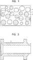
- FIG. 1 is a schematic view illustrating a heat radiation path of the electrical insulating material.
- An epoxy resin 1 contains a predetermined amount of silica 2 and magnesia 3 filled therein. It is considered that heat transfer is performed in a manner to transfer via the magnesia 3 adjacent to each other as indicated by the dotted line arrow.
- the electrical insulating material includes the inorganic particle filler containing the magnesia 3 and the silica 2 mixed in a weight ratio of 85:15 to 50:50.
- the volume fraction of the inorganic particle filler containing the magnesia 3 and the silica 2 is preferably set to 45 to 51 Vol% with respect to the entire electrical insulating material.
- the volume fraction of the inorganic particle filler exceeds 60 Vol% with respect to the entire electrical insulating material, the viscosity of the epoxy resin increases to be unsuitable for molding work.
- a particle diameter of the magnesia 3 is smaller than a particle diameter of the silica 2, the magnesia 3 are dispersed and spreaded uniformly therein to improve heat transfer.
- FIG. 2 is a partial cross-sectional view illustrating structure of a molded bus including an insulating layer 5 using the electrical insulating material of the embodiment provided around a bar-shaped center conductor 4 made of aluminum. Both ends in the axial direction of the insulating layer 5 are a tapered interface connecting portion, respectively. A ground layer may be provided on the outer periphery of the insulating layer 5.
- the thermal expansion coefficient of aluminum is 23.0 ppm/K and is equal to the thermal expansion coefficient of the insulating layer 5 made of the electrical insulating material of the embodiment, so that it is possible to improve the crack resistance. Further, a heat radiation property from the insulating layer 5 improves, so that it is possible to achieve an increase in capacity.
- the thermal expansion coefficient of the electrical insulating material is preferable to be the same as or slightly larger than the thermal expansion coefficient of a material constituting the electrical member.
- electrolytic copper having a thermal expansion coefficient smaller than that of aluminum can be used.
- FIG. 3 is a partial cross-sectional view illustrating structure of a molded vacuum valve that includes brass-made electric field relaxing rings 7 provided on a vacuum valve 6 having a pair of contacts capable of easily coming into contact with and separating from each other, and an insulating layer 8 using the electrical insulating material of the embodiment. Both ends in the axial direction of the insulating layer 8 are a tapered interface connecting portion, respectively. A ground layer may be provided on the outer periphery of the insulating layer 8.
- the thermal expansion coefficient of brass is 18.0 to 23.0 ppm/K and is equal to or smaller than the thermal expansion coefficient of the insulating layer 8 made of the electrical insulating material of the embodiment, so that it is possible to improve the crack resistance. Further, heat radiation from the contacts where heat is easily generated can be promoted.
- Various materials such as alumina porcelain and iron alloy can be used for the vacuum valve 6, by controlling thermal expansion coefficient, the crack resistance can be improved.
- the center conductor 4 and the vacuum valve 6 are respectively an electrical member used in a power reception/distribution apparatus.
- the one obtained by embedding the electrical member in the insulating layer 5 or the insulating layer 8 becomes the molded electrical apparatus.
- the electrical member is coated with the insulating layers 5 or the insulating layer 8.
- the electrical insulating material of the embodiment since the inorganic particle filler containing a predetermined amount of the silica 2 mixed with the magnesia 3 is filled in the epoxy resin 1 as a thermosetting matrix resin, the electrical insulating material can maintain good thermal conductivity while suppressing an increase in the thermal expansion coefficient. Further, the molded electrical apparatus in which the electrical member is molded from the electrical insulating material contains a plurality of types of materials embedded therein, and the crack resistance and the heat radiation property of the molded electrical apparatus can be improved.
- the embodiment has been explained using the inorganic particle filler containing the magnesia 3 and silica 2, but alumina, boron nitride, and/or the like can be further mixed in the inorganic particle filler. Further, when a particle with flexibility such as rubber particle is mixed in the inorganic particle filler, it is possible to improve toughness.
- Comparative example 1 was a conventional electrical insulating material using silica as an inorganic particle filler, and the thermal expansion coefficient was 20.5 ppm/K and the thermal conductivity was 0.5 W/m ⁇ K.
- the silica is spherical and a particle diameter thereof is 10 to 50 ⁇ m. The same is true of Comparative example and Examples below.
- Comparative example 2 was an electrical insulating material in which silica was all replaced with magnesia as an inorganic particle filler, and the thermal expansion coefficient was 25.2 ppm/K and the thermal conductivity was 1.6 W/m ⁇ K.
- the shape of magnesia particle is the degree to which their corners are rounded off, and a particle diameter of the magnesia is 10 to 50 ⁇ m similarly to the silica.
- the thermal conductivity was about three times that of Comparative example 1 to be good, but the thermal expansion coefficient increased significantly to be larger than the thermal expansion coefficient of the electrical member to be embedded in the above-described molded electrical apparatus.
- Example 1 as an inorganic particle filler, the magnesia and the silica were mixed in a weight ratio of 85:15 to be filled in an epoxy resin.
- the volume fraction of the inorganic particle filler is 51 Vol%.
- the thermal expansion coefficient was 23.0 ppm/K and the thermal conductivity was 1.4 W/m ⁇ K.
- the thermal expansion coefficient became equivalent to the thermal expansion coefficient of the electrical member to be embedded in the above-described molded electrical apparatus, and the thermal conductivity was about three times that of Comparative example 1.
- Example 2 the magnesia and the silica were mixed in a weight ratio of 50:50 to be filled in an epoxy resin.
- the volume fraction of the inorganic particle filler is 51 Vol%, which is the same as that of Example 1.
- the thermal expansion coefficient and the thermal conductivity were both good.
- Example 3 the magnesia and the silica were mixed in a weight ratio of 50:50 similarly to Example 2 to be filled in an epoxy resin.
- the volume fraction of the inorganic particle filler is 45 Vol%.
- the thermal expansion coefficient was 23.0 ppm/K and the thermal conductivity was 0.8 W/m ⁇ K.
- the thermal conductivity is about 1.6 times that of Comparative example 1.
Landscapes
- Chemical & Material Sciences (AREA)
- Health & Medical Sciences (AREA)
- Chemical Kinetics & Catalysis (AREA)
- Medicinal Chemistry (AREA)
- Polymers & Plastics (AREA)
- Organic Chemistry (AREA)
- Physics & Mathematics (AREA)
- Spectroscopy & Molecular Physics (AREA)
- Organic Insulating Materials (AREA)
- Compositions Of Macromolecular Compounds (AREA)
- High-Tension Arc-Extinguishing Switches Without Spraying Means (AREA)
- Inorganic Insulating Materials (AREA)
Abstract
Description
- Embodiments described herein relate generally to an electrical insulating material and a molded electrical apparatus.
- Conventionally, for a molded electrical apparatus in which an electrical member such as a vacuum valve is molded from an epoxy resin, a plurality of members different in thermal expansion coefficient are embedded in an insulating layer, so that an electrical insulating material with improved crack resistance has been used. However, spherical silica being an inorganic particle filler that affects the crack resistance has been disadvantageous to the molded electrical apparatus that uses a large amount of resin in terms of cost when considering manufacturing processes.
- In the meantime, magnesia (MgO) has been known as a relatively inexpensive inorganic particle filler. Magnesia is excellent in thermal conductivity and thus is used in large amounts for a sealing material of a semiconductor that requires heat resistance. However, the thermal expansion coefficient of magnesia is 13.1 ppm/K, which is extraordinarily large as compared to silica or the like, and therefore there has been a limit to an improvement in crack resistance.
- For this reason, for the molded electrical apparatus, one capable of effectively bringing out the effect of silica and improving the crack resistance by suppressing a thermal expansion coefficient of an entire electrical insulating material with use of, as an inorganic particle filler, magnesia capable of achieving a reduction in cost by mass production has been desired. A recent molded electrical apparatus tends to be large in capacity and is affected by a large temperature rise, so that maintaining excellent thermal conductivity is also required.
-
- Patent Reference 1:
JP-A 2002-015621 - Patent Reference 2:
JP-A 2012-188629 - A problem to be solved by the embodiments is to provide an electrical insulating material and a molded electrical apparatus that have both excellent thermal conductivity and excellent crack resistance with use of magnesia as an inorganic particle filler.
- An electrical insulating material of an embodiment includes an epoxy resin, an inorganic particle filler containing magnesia and silica mixed in a weight ratio of 85:15 to 50:50, and a curing agent.
-
-
Fig. 1 is a schematic view illustrating a heat radiation path of an electrical insulating material according to an embodiment. -
Fig. 2 is a partial cross-sectional view illustrating structure of a molded bus molded from the electrical insulating material according to an embodiment. -
Fig. 3 is a partial cross-sectional view illustrating structure of a molded vacuum valve molded from the electrical insulating material according to an embodiment. -
Fig. 4 is a diagram illustrating components of electrical insulating materials according to Examples and Comparative examples. -
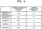
Fig. 5 is a diagram illustrating measurement results of various properties of sample sheets molded from the electrical insulating materials according to Examples and Comparative examples. - Hereinafter, there will be explained embodiments with reference to the drawings.
- An electrical insulating material of an embodiment includes an epoxy resin, an inorganic particle filler containing magnesia and silica mixed in a weight ratio of 85:15 to 50:50, and a curing agent.
FIG. 1 is a schematic view illustrating a heat radiation path of the electrical insulating material. Anepoxy resin 1 contains a predetermined amount ofsilica 2 andmagnesia 3 filled therein. It is considered that heat transfer is performed in a manner to transfer via themagnesia 3 adjacent to each other as indicated by the dotted line arrow. In order to maintain such a path, the electrical insulating material includes the inorganic particle filler containing themagnesia 3 and thesilica 2 mixed in a weight ratio of 85:15 to 50:50. Further, the volume fraction of the inorganic particle filler containing themagnesia 3 and thesilica 2 is preferably set to 45 to 51 Vol% with respect to the entire electrical insulating material. When the volume fraction of the inorganic particle filler exceeds 60 Vol% with respect to the entire electrical insulating material, the viscosity of the epoxy resin increases to be unsuitable for molding work. When a particle diameter of themagnesia 3 is smaller than a particle diameter of thesilica 2, themagnesia 3 are dispersed and spreaded uniformly therein to improve heat transfer. - For these reasons, by mixing a predetermined amount of the
silica 2 with themagnesia 3 that is used in large amounts in other fields and is industrially valuable in terms of cost by mass production, good thermal conductivity can be maintained while suppressing an increase in the thermal expansion coefficient. When an electrical member is molded from such an electrical insulating material, it is possible to exhibit excellent crack resistance and thermal conductivity. -
FIG. 2 is a partial cross-sectional view illustrating structure of a molded bus including aninsulating layer 5 using the electrical insulating material of the embodiment provided around a bar-shaped center conductor 4 made of aluminum. Both ends in the axial direction of theinsulating layer 5 are a tapered interface connecting portion, respectively. A ground layer may be provided on the outer periphery of theinsulating layer 5. The thermal expansion coefficient of aluminum is 23.0 ppm/K and is equal to the thermal expansion coefficient of the insulatinglayer 5 made of the electrical insulating material of the embodiment, so that it is possible to improve the crack resistance. Further, a heat radiation property from theinsulating layer 5 improves, so that it is possible to achieve an increase in capacity. The thermal expansion coefficient of the electrical insulating material is preferable to be the same as or slightly larger than the thermal expansion coefficient of a material constituting the electrical member. For thecenter conductor 4, electrolytic copper having a thermal expansion coefficient smaller than that of aluminum can be used. - Next,
FIG. 3 is a partial cross-sectional view illustrating structure of a molded vacuum valve that includes brass-made electricfield relaxing rings 7 provided on avacuum valve 6 having a pair of contacts capable of easily coming into contact with and separating from each other, and aninsulating layer 8 using the electrical insulating material of the embodiment. Both ends in the axial direction of theinsulating layer 8 are a tapered interface connecting portion, respectively. A ground layer may be provided on the outer periphery of theinsulating layer 8. The thermal expansion coefficient of brass is 18.0 to 23.0 ppm/K and is equal to or smaller than the thermal expansion coefficient of the insulatinglayer 8 made of the electrical insulating material of the embodiment, so that it is possible to improve the crack resistance. Further, heat radiation from the contacts where heat is easily generated can be promoted. Various materials such as alumina porcelain and iron alloy can be used for thevacuum valve 6, by controlling thermal expansion coefficient, the crack resistance can be improved. - The
center conductor 4 and thevacuum valve 6 are respectively an electrical member used in a power reception/distribution apparatus. The one obtained by embedding the electrical member in theinsulating layer 5 or theinsulating layer 8 becomes the molded electrical apparatus. The electrical member is coated with theinsulating layers 5 or theinsulating layer 8. - According to the electrical insulating material of the embodiment, since the inorganic particle filler containing a predetermined amount of the
silica 2 mixed with themagnesia 3 is filled in theepoxy resin 1 as a thermosetting matrix resin, the electrical insulating material can maintain good thermal conductivity while suppressing an increase in the thermal expansion coefficient. Further, the molded electrical apparatus in which the electrical member is molded from the electrical insulating material contains a plurality of types of materials embedded therein, and the crack resistance and the heat radiation property of the molded electrical apparatus can be improved. - The embodiment has been explained using the inorganic particle filler containing the
magnesia 3 andsilica 2, but alumina, boron nitride, and/or the like can be further mixed in the inorganic particle filler. Further, when a particle with flexibility such as rubber particle is mixed in the inorganic particle filler, it is possible to improve toughness. - Hereinafter, it will be explained in detail with reference to examples. Note that the embodiments are not limited by the examples.
- Components of electrical insulating materials and measurement results of a thermal expansion coefficient and thermal conductivity of sample sheets molded from the electrical insulating materials are explained with reference to
FIG. 4 andFIG. 5 . Molding was general casting, and the measurements of the thermal expansion coefficient and the thermal conductivity were in conformity to the relevant JIS Standards. - Comparative example 1 was a conventional electrical insulating material using silica as an inorganic particle filler, and the thermal expansion coefficient was 20.5 ppm/K and the thermal conductivity was 0.5 W/m·K. The silica is spherical and a particle diameter thereof is 10 to 50 µm. The same is true of Comparative example and Examples below.
- Comparative example 2 was an electrical insulating material in which silica was all replaced with magnesia as an inorganic particle filler, and the thermal expansion coefficient was 25.2 ppm/K and the thermal conductivity was 1.6 W/m·K. The shape of magnesia particle is the degree to which their corners are rounded off, and a particle diameter of the magnesia is 10 to 50 µm similarly to the silica. The same is true of Examples below. As a result, the thermal conductivity was about three times that of Comparative example 1 to be good, but the thermal expansion coefficient increased significantly to be larger than the thermal expansion coefficient of the electrical member to be embedded in the above-described molded electrical apparatus.
- In Example 1, as an inorganic particle filler, the magnesia and the silica were mixed in a weight ratio of 85:15 to be filled in an epoxy resin. The volume fraction of the inorganic particle filler is 51 Vol%. As a result, the thermal expansion coefficient was 23.0 ppm/K and the thermal conductivity was 1.4 W/m·K. The thermal expansion coefficient became equivalent to the thermal expansion coefficient of the electrical member to be embedded in the above-described molded electrical apparatus, and the thermal conductivity was about three times that of Comparative example 1.
- In Example 2, the magnesia and the silica were mixed in a weight ratio of 50:50 to be filled in an epoxy resin. The volume fraction of the inorganic particle filler is 51 Vol%, which is the same as that of Example 1. As a result, the thermal expansion coefficient and the thermal conductivity were both good.
- In Example 3, the magnesia and the silica were mixed in a weight ratio of 50:50 similarly to Example 2 to be filled in an epoxy resin. The volume fraction of the inorganic particle filler is 45 Vol%. As a result, the thermal expansion coefficient was 23.0 ppm/K and the thermal conductivity was 0.8 W/m·K. The thermal conductivity is about 1.6 times that of Comparative example 1.
- While certain embodiments of the present invention have been described, these embodiments have been presented by way of example only, and are not intended to limit the scope of the inventions. Indeed, the novel embodiments described herein may be embodied in a variety of other forms; furthermore, various omissions, substitutions and changes in the form of the embodiments described herein may be made without departing from the spirit of the inventions. The accompanying claims and their equivalents are intended to cover such forms or modifications as would fall within the scope and spirit of the inventions.
Claims (6)
- An electrical insulating material, comprising:an epoxy resin;an inorganic particle filler containing magnesia and silica mixed in a weight ratio of 85:15 to 50:50; anda curing agent.
- The electrical insulating material of to claim 1,
wherein the inorganic particle filler is set to 45 to 51 Vol%. - The electrical insulating material of to claim 1 or 2,
wherein the magnesia has a particle diameter smaller than a particle diameter of the silica. - A molded electrical apparatus, comprising:an electrical member used in a power reception/distribution apparatus; andan insulating layer coating the electrical member, the insulating layer being made of an electrical insulating material including:an epoxy resin;an inorganic particle filler containing magnesia and silica mixed in a weight ratio of 85:15 to 50:50; anda curing agent.
- The molded electrical apparatus of to claim 4,
wherein the electrical member is a vacuum valve. - The molded electrical apparatus of to claim 4 or 5,
wherein the electrical member has a thermal expansion coefficient equal to or smaller than a thermal expansion coefficient of the electrical insulating material.
Applications Claiming Priority (2)
| Application Number | Priority Date | Filing Date | Title |
|---|---|---|---|
| JP2014048601A JP6322794B2 (en) | 2014-03-12 | 2014-03-12 | Electrical insulation materials and molded electrical equipment |
| PCT/JP2015/001346 WO2015136932A1 (en) | 2014-03-12 | 2015-03-11 | Electrical insulation material and mold electric apparatus |
Publications (2)
| Publication Number | Publication Date |
|---|---|
| EP3118259A1 true EP3118259A1 (en) | 2017-01-18 |
| EP3118259A4 EP3118259A4 (en) | 2017-11-15 |
Family
ID=54071389
Family Applications (1)
| Application Number | Title | Priority Date | Filing Date |
|---|---|---|---|
| EP15761064.3A Withdrawn EP3118259A4 (en) | 2014-03-12 | 2015-03-11 | Electrical insulation material and mold electric apparatus |
Country Status (4)
| Country | Link |
|---|---|
| EP (1) | EP3118259A4 (en) |
| JP (1) | JP6322794B2 (en) |
| CN (1) | CN106103586A (en) |
| WO (1) | WO2015136932A1 (en) |
Families Citing this family (1)
| Publication number | Priority date | Publication date | Assignee | Title |
|---|---|---|---|---|
| JP6975098B2 (en) * | 2018-05-25 | 2021-12-01 | 株式会社日立産機システム | Solid insulation switches and railcars |
Family Cites Families (10)
| Publication number | Priority date | Publication date | Assignee | Title |
|---|---|---|---|---|
| JPS6044519A (en) * | 1983-08-23 | 1985-03-09 | Showa Denko Kk | Epoxy resin composition for electrical circuit casting |
| JPH0848857A (en) * | 1994-08-09 | 1996-02-20 | Toshiba Corp | Resin molded product |
| JPH08143781A (en) * | 1994-11-22 | 1996-06-04 | Sumitomo Bakelite Co Ltd | Thermosetting resin composition |
| JP4969816B2 (en) * | 2005-08-22 | 2012-07-04 | 株式会社東芝 | RESIN COMPOSITION, PROCESS FOR PRODUCING THE SAME AND ELECTRIC DEVICE USING THE SAME |
| JP5269728B2 (en) * | 2009-09-07 | 2013-08-21 | 株式会社日立エレクトリックシステムズ | High toughness and high thermal conductivity curable resin composition, cured product thereof and molded electric machine |
| JP2011079964A (en) * | 2009-10-07 | 2011-04-21 | Hitachi Chem Co Ltd | Electrical insulation material, method for producing the same and method for producing electric instrument insulation material by using the same |
| JP5447355B2 (en) * | 2010-12-02 | 2014-03-19 | 新神戸電機株式会社 | Method for producing thermosetting resin composition, method for producing prepreg and laminate |
| JP5507477B2 (en) * | 2011-01-20 | 2014-05-28 | パナソニック株式会社 | Epoxy resin composition for semiconductor encapsulation and semiconductor device |
| US20150034369A1 (en) * | 2011-07-14 | 2015-02-05 | Mitsubishi Gas Chemical Company, Inc. | Resin composition for printed wiring boards |
| JP5913884B2 (en) * | 2011-09-27 | 2016-04-27 | 積水化学工業株式会社 | Insulating material and laminated structure |
-
2014
- 2014-03-12 JP JP2014048601A patent/JP6322794B2/en active Active
-
2015
- 2015-03-11 WO PCT/JP2015/001346 patent/WO2015136932A1/en not_active Ceased
- 2015-03-11 EP EP15761064.3A patent/EP3118259A4/en not_active Withdrawn
- 2015-03-11 CN CN201580013264.3A patent/CN106103586A/en active Pending
Also Published As
| Publication number | Publication date |
|---|---|
| WO2015136932A1 (en) | 2015-09-17 |
| CN106103586A (en) | 2016-11-09 |
| EP3118259A4 (en) | 2017-11-15 |
| JP6322794B2 (en) | 2018-05-16 |
| JP2015173056A (en) | 2015-10-01 |
Similar Documents
| Publication | Publication Date | Title |
|---|---|---|
| JP6520966B2 (en) | Prepreg mica tape and coil using the same | |
| JP2014520172A5 (en) | ||
| EP3104404B1 (en) | Thermally conductive sheet and semiconductor device | |
| MY184840A (en) | A thermosetting epoxy resin composition for the preparation of outdoor articles, and the articles obtained therefrom | |
| KR20180118738A (en) | A rotating electric coil, a method of manufacturing a coil for a rotating electric machine, a mica tape, a hardened material and an insulating material of a mica tape | |
| CN105969277A (en) | Heat-dissipating pouring sealant for packaging electronic devices | |
| MX2017012200A (en) | A thermosetting epoxy resin composition for the preparation of outdoor articles, and the articles obtained therefrom. | |
| KR20140120267A (en) | Coating material for electrical equipment, method for producing the same, and sealed type isolator | |
| CN105754535A (en) | Insulating heat-conducting adhesive and preparation method thereof | |
| MX2017012199A (en) | A process for the preparation of insulation systems for electrical engineering, the articles obtained therefrom and the use thereof. | |
| US10269689B2 (en) | Thermally conductive sheet and semiconductor device | |
| CN105062358B (en) | A kind of high heat conductive insulating aluminium base | |
| WO2013123648A1 (en) | Curable epoxy composition with milled glass fiber | |
| CN105579506B (en) | Heat conductive filler and the heat conductivity resin combination containing it | |
| JP6152321B2 (en) | Epoxy resin composition for casting ignition coil, ignition coil and method for producing the same | |
| WO2019111298A1 (en) | Insulating spacer | |
| KR102279438B1 (en) | Epoxy resin composition and transformer comprising the same | |
| JP6322794B2 (en) | Electrical insulation materials and molded electrical equipment | |
| CN106007708A (en) | Ceramic material | |
| CN105448497B (en) | A kind of dry-type distribution transformer | |
| JP2008141809A (en) | Resin molded insulated conductor | |
| JP2019121487A (en) | Solid insulation switchgear | |
| KR102611441B1 (en) | Electrically insulated and heat radiated coating composition and electrically insulated and heat radiated commodities with the same | |
| CN104927174A (en) | Cable housing insulation material and preparation method thereof | |
| JP5615475B2 (en) | Manufacturing method of insulation material for all-solid-state transformer |
Legal Events
| Date | Code | Title | Description |
|---|---|---|---|
| STAA | Information on the status of an ep patent application or granted ep patent |
Free format text: STATUS: THE INTERNATIONAL PUBLICATION HAS BEEN MADE |
|
| PUAI | Public reference made under article 153(3) epc to a published international application that has entered the european phase |
Free format text: ORIGINAL CODE: 0009012 |
|
| STAA | Information on the status of an ep patent application or granted ep patent |
Free format text: STATUS: REQUEST FOR EXAMINATION WAS MADE |
|
| 17P | Request for examination filed |
Effective date: 20160810 |
|
| AK | Designated contracting states |
Kind code of ref document: A1 Designated state(s): AL AT BE BG CH CY CZ DE DK EE ES FI FR GB GR HR HU IE IS IT LI LT LU LV MC MK MT NL NO PL PT RO RS SE SI SK SM TR |
|
| AX | Request for extension of the european patent |
Extension state: BA ME |
|
| DAV | Request for validation of the european patent (deleted) | ||
| DAX | Request for extension of the european patent (deleted) | ||
| A4 | Supplementary search report drawn up and despatched |
Effective date: 20171017 |
|
| RIC1 | Information provided on ipc code assigned before grant |
Ipc: C08L 63/00 20060101AFI20171010BHEP Ipc: H01B 3/40 20060101ALI20171010BHEP Ipc: C08K 3/22 20060101ALI20171010BHEP Ipc: H01B 3/00 20060101ALI20171010BHEP |
|
| STAA | Information on the status of an ep patent application or granted ep patent |
Free format text: STATUS: THE APPLICATION HAS BEEN WITHDRAWN |
|
| 18W | Application withdrawn |
Effective date: 20191212 |