EP3117947A1 - Method of determining quality of cladding layer and laser build-up apparatus - Google Patents
Method of determining quality of cladding layer and laser build-up apparatus Download PDFInfo
- Publication number
- EP3117947A1 EP3117947A1 EP16175404.9A EP16175404A EP3117947A1 EP 3117947 A1 EP3117947 A1 EP 3117947A1 EP 16175404 A EP16175404 A EP 16175404A EP 3117947 A1 EP3117947 A1 EP 3117947A1
- Authority
- EP
- European Patent Office
- Prior art keywords
- cladding layer
- image
- melt pool
- laser
- quality
- Prior art date
- Legal status (The legal status is an assumption and is not a legal conclusion. Google has not performed a legal analysis and makes no representation as to the accuracy of the status listed.)
- Granted
Links
Images





Classifications
-
- B—PERFORMING OPERATIONS; TRANSPORTING
- B23—MACHINE TOOLS; METAL-WORKING NOT OTHERWISE PROVIDED FOR
- B23K—SOLDERING OR UNSOLDERING; WELDING; CLADDING OR PLATING BY SOLDERING OR WELDING; CUTTING BY APPLYING HEAT LOCALLY, e.g. FLAME CUTTING; WORKING BY LASER BEAM
- B23K31/00—Processes relevant to this subclass, specially adapted for particular articles or purposes, but not covered by any single one of main groups B23K1/00 - B23K28/00
- B23K31/12—Processes relevant to this subclass, specially adapted for particular articles or purposes, but not covered by any single one of main groups B23K1/00 - B23K28/00 relating to investigating the properties, e.g. the weldability, of materials
- B23K31/125—Weld quality monitoring
-
- B—PERFORMING OPERATIONS; TRANSPORTING
- B23—MACHINE TOOLS; METAL-WORKING NOT OTHERWISE PROVIDED FOR
- B23K—SOLDERING OR UNSOLDERING; WELDING; CLADDING OR PLATING BY SOLDERING OR WELDING; CUTTING BY APPLYING HEAT LOCALLY, e.g. FLAME CUTTING; WORKING BY LASER BEAM
- B23K26/00—Working by laser beam, e.g. welding, cutting or boring
- B23K26/02—Positioning or observing the workpiece, e.g. with respect to the point of impact; Aligning, aiming or focusing the laser beam
- B23K26/03—Observing, e.g. monitoring, the workpiece
- B23K26/032—Observing, e.g. monitoring, the workpiece using optical means
-
- B—PERFORMING OPERATIONS; TRANSPORTING
- B23—MACHINE TOOLS; METAL-WORKING NOT OTHERWISE PROVIDED FOR
- B23K—SOLDERING OR UNSOLDERING; WELDING; CLADDING OR PLATING BY SOLDERING OR WELDING; CUTTING BY APPLYING HEAT LOCALLY, e.g. FLAME CUTTING; WORKING BY LASER BEAM
- B23K26/00—Working by laser beam, e.g. welding, cutting or boring
- B23K26/34—Laser welding for purposes other than joining
-
- B—PERFORMING OPERATIONS; TRANSPORTING
- B23—MACHINE TOOLS; METAL-WORKING NOT OTHERWISE PROVIDED FOR
- B23K—SOLDERING OR UNSOLDERING; WELDING; CLADDING OR PLATING BY SOLDERING OR WELDING; CUTTING BY APPLYING HEAT LOCALLY, e.g. FLAME CUTTING; WORKING BY LASER BEAM
- B23K26/00—Working by laser beam, e.g. welding, cutting or boring
- B23K26/70—Auxiliary operations or equipment
- B23K26/702—Auxiliary equipment
-
- G—PHYSICS
- G06—COMPUTING OR CALCULATING; COUNTING
- G06T—IMAGE DATA PROCESSING OR GENERATION, IN GENERAL
- G06T2207/00—Indexing scheme for image analysis or image enhancement
- G06T2207/30—Subject of image; Context of image processing
- G06T2207/30108—Industrial image inspection
- G06T2207/30164—Workpiece; Machine component
Definitions
- the present invention relates to a method of determining a quality of a cladding layer and a laser build-up apparatus, and relates to, for example, a method of determining a quality of a cladding layer for a valve seat and a laser build-up apparatus for the valve seat.
- a laser cladding process that irradiates a laser beam while a metallic powder is being supplied to form a cladding layer is used, for example, to form a valve seat of a cylinder head.
- Japanese Unexamined Patent Application Publication No. 09-192861 discloses an apparatus in which the intensity of light emitted from a melt pool in the laser cladding process is observed by a plurality of optical sensors and the presence or the absence of an abnormality in the cladding layer is determined.
- the present inventors have found that holes (blow holes) are generated when excess metallic powder (excess powder) deposited at the front of the direction in which a melt pool moves aggregates, the state of the excess metallic powder becomes a semi-molten one since a laser beam comes close to it, the excess metallic powder becomes balls (ball-shaped metal aggregates) having a relatively large size, and then the balls are absorbed in the melt pool.
- holes are generated when excess metallic powder (excess powder) deposited at the front of the direction in which a melt pool moves aggregates, the state of the excess metallic powder becomes a semi-molten one since a laser beam comes close to it, the excess metallic powder becomes balls (ball-shaped metal aggregates) having a relatively large size, and then the balls are absorbed in the melt pool.
- the present invention has been made in order to solve the above problem and aims to provide a method of determining a quality of a cladding layer and a laser build-up apparatus capable of accurately determining the quality of the cladding layer.
- a method of determining a quality of a cladding layer is a method of determining a quality of a cladding layer formed by irradiating a laser beam while a metallic powder is being supplied, the method including: a process of capturing an image of a melt pool and an area around thereof while the cladding layer is being formed; a process of measuring the sizes and the number of ball-shaped metallic powder aggregates absorbed in the melt pool from the image that has been captured; and a process of determining the quality of the cladding layer based on the sizes and the number that have been measured.
- an optical axis of the laser beam that illuminates the melt pool be made coincident with an optical axis of light to capture the image of the melt pool and the area around thereof. According to this configuration, it is possible to capture the whole image of the melt pool and the area around thereof.
- a laser build-up apparatus includes: a supply part that supplies a metallic powder; and a laser oscillator that outputs a laser beam, in which: a cladding layer is formed by irradiating the laser beam while the metallic power is being supplied from the supply part, the laser build-up apparatus further includes: an image-capture unit that captures an image of a melt pool and an area around thereof; and a measurement unit that measures the sizes and the number of ball-shaped metallic powder aggregates absorbed in the melt pool from the image that has been captured, and a quality of the cladding layer is determined based on the sizes and the number of the metallic powder aggregates.
- a nozzle having a central axis be further included and an optical axis of the laser beam that illuminates the melt pool and an optical axis of light to capture the images of the melt pool and the area around thereof coincide with the central axis. According to this configuration, it is possible to capture the whole image of the melt pool and the area around thereof.
- the present invention it is possible to provide a method of determining a quality of a cladding layer and a laser build-up apparatus capable of accurately determining the quality of the cladding layer.
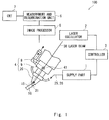
- Fig. 1 is a configuration diagram that exemplifies a laser build-up apparatus according to a first embodiment.
- a laser build-up apparatus 100 includes a supply part 1, a laser oscillator 2, a controller 3, a laser processing part 4, an image processor 5, a measurement and determination unit 6, and a determination result display unit 7.
- the laser processing part 4 includes an image-capture unit 8, a case 9, and a laser clad head 20.
- the supply part 1 supplies a metallic powder 26.
- the supply part 1 mixes a carrier gas 25 with the metallic powder 26 and supplies the metallic powder 26 together with the carrier gas 25 to the laser clad head 20. Further, the supply part 1 supplies a center gas 24 to the laser clad head 20.
- the center gas 24 and the carrier gas 25 are, for example, each an inactive gas such as nitrogen or argon.
- the metallic powder 26 includes, for example, copper powder.
- the laser oscillator 2 outputs a laser beam 30.
- the laser beam 30 that is output passes through the case 9 and the laser clad head 20 and illuminates a processing point (melt pool 31).
- the controller 3 controls supply and stop of supply of powder in the supply part 1 and output and stop of the laser in the laser oscillator 2.
- the controller 3 further controls the flow rate of the center gas 24 and the carrier gas 25, the supply amount of the metallic powder 26, and the output of the laser beam 30.
- a beam splitter 41 is provided inside the case 9 of the laser processing part 4.
- the beam splitter 41 reflects a part of the light that has been input and transmits the other part of the light.
- the beam splitter 41 transmits a part of the laser beam 30 from the laser oscillator 2 to the side of the processing point (melt pool 31) and reflects the other part of the light from the melt pool 31 and the area around thereof to the side of the image-capture unit 8.
- the laser clad head 20 is attached to the case 9.
- the laser clad head 20 emits the laser beam 30 that has transmitted the beam splitter 41 to the processing point. Further, the laser clad head 20 discharges the metallic powder 26 that has been supplied to the processing point. In this way, by irradiating the laser beam 30 while the metallic powder 26 is being supplied, a cladding layer 16 is formed.
- the melt pool 31 is formed on the surface of the cladding layer 16 opposed to the laser clad head 20.
- the laser clad head 20 delivers the light emitted from the melt pool 31 and the area around thereof to the beam splitter 41.
- Fig. 2 is a cross-sectional view that exemplifies the laser clad head of the laser build-up apparatus according to the first embodiment.
- the laser clad head 20 includes an inner nozzle 21, an outer nozzle 22, and a raw material supply pipe 23.
- the laser clad head 20 has a coaxial double-tube structure including the inner nozzle 21 and the outer nozzle 22 both having an optical axis A1 of the laser beam 30 as a central axis.
- the laser beam 30 is emitted from the inner nozzle 21.
- light to capture the image of the melt pool 31 and the area around thereof is input to the inner nozzle 21.
- the optical axis A1 of the laser beam 30 that illuminates the melt pool 31 and the optical axis of the light to capture the image of the melt pool 31 and the area around thereof coincide with each other in the laser clad head 20.
- the center gas 24 is discharged from the inner nozzle 21. Further, the carrier gas 25 and the metallic powder 26 supplied via the raw material supply pipe 23 are discharged from between the inner nozzle 21 and the outer nozzle 22.
- the optical axis A1 of the laser beam 30 that illuminates the melt pool 31 and the optical axis of the light to capture the image of the melt pool 31 and the area around thereof coincide with the central axis of the inner nozzle 21 and the outer nozzle 22.
- the size of the laser processing part 4 can be reduced. Further, since the optical axis of the laser beam 30 that illuminates the melt pool 31 and the optical axis of the light to capture the image of the melt pool 31 and the area around thereof coincide with each other in the laser clad head 20, the whole image of the melt pool 31 and the area around thereof can be captured.
- the image-capture unit 8 is attached to the case 9.
- the light emitted from the melt pool 31 and the area around thereof is reflected by the beam splitter 41 in the case 9 and then the image-capture unit 8 receives the reflected light.
- the image-capture unit 8 therefore captures the image of the melt pool 31 and the area around thereof.
- the image-capture unit 8 is, for example, a Charge-Coupled Device (CCD) camera.
- CCD Charge-Coupled Device
- the image processor 5 processes the image captured by the image-capture unit 8. For example, the image processor 5 creates a black-white contrast on the image by changing the intensity of brightness.
- the measurement and determination unit 6 performs measurement and determination based on the image that has been processed. Accordingly, the measurement and determination unit 6 measures the sizes and the number of ball-shaped metallic powder aggregates (balls) absorbed in the melt pool 31 from the image that has been captured. The measurement and determination unit 6 further measures the number of holes in the cladding layer 16. The measurement and determination unit 6 further calculates the area of the balls for each contrast created by the image processor 5.
- the determination result display unit 7 displays the image that has been captured and the image that has been processed.
- the determination result display unit 7 further displays the sizes and the number of balls that have been measured.
- the determination result display unit 7 further displays the number of holes.
- the determination result display unit 7 further displays the result of determining the quality of the cladding layer 16 that has been measured.
- the determination result display unit 7 is, for example, a Cathode Ray Tube (CRT).
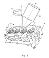
- Fig. 3 is a perspective view that exemplifies a laser build-up method according to the first embodiment.
- the cylinder head roughly formed material 10 is casting formed of, for example, cast iron or aluminum alloy.
- the cylinder head roughly formed material 10 includes a plurality of combustion chambers 11.
- Each of the combustion chambers 11 includes an inlet port 12 and an outlet port 13.
- an annular counter sunk groove 15 that surrounds an opening 14 is formed along the periphery of the opening 14 on the side of the combustion chamber 11.
- the counter sunk groove 15 is formed by machine processing.
- the cylinder head roughly formed material 10 shown in Fig. 3 is for 4-cylinder, 16-valve engines and includes two inlet ports 12 and two outlet ports 13 in each of the four combustion chambers 11.
- the number of combustion chambers 11, the number of inlet ports 12, and the number of outlet ports 13 are not limited to those shown in the example of Fig. 3 and are determined as appropriate.
- the controller 3 causes the supply part 1 to mix the carrier gas 25 with the metallic powder 26.
- the controller 3 further causes the laser oscillator 2 to start operation.
- the controller 3 controls the supply part 1 and causes the supply part 1 to supply the carrier gas 25 in which the center gas 24 and the metallic powder 26 are mixed to the laser clad head 20.
- the controller 3 controls the laser oscillator 2 and causes the laser oscillator 2 to emit the laser beam 30 to the case 9.
- the controller 3 matches the timing of the supply of the metallic powder 26 with the emission of the laser beam 30.
- the laser beam 30 emitted to the case 9 passes through the case 9 and reaches the beam splitter 41.
- the beam splitter 41 allows a part of the laser beam 30 to pass therethrough.
- the center gas 24 supplied to the laser clad head 20 is discharged from the inner nozzle 21.
- the carrier gas 25 and the metallic powder 26 are discharged to the inside of the counter sunk groove 15 from between the inner nozzle 21 and the outer nozzle 22.
- the laser beam 30 that has been transmitted through the beam splitter 41 passes through the inner nozzle 21 of the laser clad head 20 and illuminates the processing point (melt pool 31) inside the counter sunk groove 15.
- the laser build-up apparatus 100 irradiates the laser beam 30 (optical axis A1) while supplying the metallic powder 26 to the counter sunk groove 15 from the supply part 1. Accordingly, the metallic powder 26 is melted and solidified inside the counter sunk groove 15 and the cladding layer 16 for the valve seat is formed.
- the melt pool 31 is formed on the surface of the cladding layer 16 opposed to the laser beam 30.
- the laser clad head 20 is rotated about a central axis A2 of the annular counter sunk groove 15.
- the cladding layer 16 is formed along the full circumference of the counter sunk groove 15.
- the direction in which the laser clad head 20 is moved is referred to as a processing direction 17.
- the central axis A2 is an axis that is vertical to two diameters that are perpendicular to each other in the circle formed by the annular form of the counter sunk groove 15 and passes through a center O, which is the center of the circle.
- the light to capture the image passes through the laser clad head 20 and reaches the beam splitter 41.
- the optical axis of the laser beam 30 that illuminates the melt pool 31 and the optical axis of the light to capture the image of the melt pool 31 and the area around thereof are made coincident with each other in the laser clad head 20.
- the light to capture the image includes, besides the light emitted from the melt pool 31, light emitted and reflected from the metallic powder aggregates that exist near the melt pool 31.
- the beam splitter 41 reflects a part of the light from the melt pool 31 and the area around thereof.
- the reflected light reaches the image-capture unit 8.
- the image-capture unit 8 therefore captures the image of the melt pool 31 and the area around thereof while the cladding layer 16 is being formed.
- the image captured by the image-capture unit 8 is processed by the image processor 5.
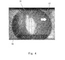
- Figs. 4 and 5 are photos that exemplify the melt pool and the area around thereof in the laser build-up apparatus according to the first embodiment.
- the melt pool 31 is formed on the tip of the cladding layer 16 in the process of forming the cladding layer 16.
- the ball 18 means the metallic powder aggregates that form a ball shape.
- the image-capture unit 8 captures the image of the melt pool 31 and the area around thereof while the cladding layer 16 is being formed. Further, the image-capture unit 8 captures the image of the ball-shaped metallic powder aggregates (balls 18) absorbed in the melt pool 31.
- Fig. 6 is a photo that exemplifies a CT image having a circular cross section when the cladding layer formed by the laser build-up apparatus according to the first embodiment is seen from the side of the combustion chamber.
- the hole 19 is observed (in the circle 19) in the circular cross section when the cladding layer 16 is seen from the side of the combustion chamber 11.
- the part in which the hole 19 was observed corresponds to the part that has sucked the ball 18 (ball sucking part 27) when the melt pool 31 was observed.
- the part in which the hole 19 was observed does not necessarily correspond to the part that has sucked the metallic powder aggregates (sucking part 32 of the metallic powder aggregates) when the melt pool 31 was observed.
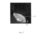
- Fig. 7 is a photo that exemplifies a CT image having a cross section taken along the line A-A' shown in Fig. 6 .
- the hole 19 is observed.
- the part in which the hole 19 was observed correspond to the ball sucking part 27.
- the image processed by the image processor 5 is transmitted to the measurement and determination unit 6.
- the measurement and determination unit 6 measures the sizes and the number of balls 18 (ball-shaped metallic powder aggregates) absorbed in the melt pool 31 from the captured image.
- the results are displayed on the determination result display unit 7.
- the quality of the cladding layer 16 is determined based on the sizes and the number of metallic powder aggregates.
- Fig. 8 is a graph that exemplifies a correlation of the sizes of the balls sucked into the melt pool and the presence or the absence of the hole inside the cladding layer in the laser build-up apparatus according to the first embodiment.
- the horizontal axis represents the sizes of the balls sucked into the melt pool and the vertical axis represents the frequency.
- the white column presents the summary of the results of the cladding layer 16 in which the hole 19 was not observed.
- the black column presents the summary of the results of the cladding layer 16 in which the hole 19 was observed.
- the number of balls 18 having the size of 1.6 to 2.0 mm ⁇ in the black column (the cladding layer 16 in which the hole 19 was observed) is larger than the number of balls in the white column (the cladding layer 16 in which the hole 19 was not observed). That is, the rate of occurrence of the hole increases as the sizes of the balls 18 increase.
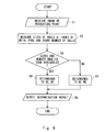
- Fig. 9 is a flowchart that exemplifies the method of determining the quality of the cladding layer in the laser build-up apparatus according to the first embodiment.
- the measurement and determination unit 6 receives an image of the processing point (melt pool 31) processed by the image processor 5.
- the measurement and determination unit 6 receives, for example, an image in which black-white contrast is created according to the brightness.
- Step S2 the sizes of the balls 18 observed at the front of the processing direction of the melt pool 31 are measured and the number of balls 18 is counted.
- the measurement of the sizes of the balls is performed, for example, by measuring the area of the contrasted image.
- Step S3 it is determined whether the sizes of the balls 18 that have been measured and the number of balls 18 that has been counted are smaller than thresholds in the quality criterion.
- the process goes to Step S4.
- the process goes to Step S5.
- Step S4 when the sizes of the balls 18 that have been measured and the number of balls 18 that has been counted are smaller than the thresholds as shown in Step S4, the cladding layer 16 that has been formed is determined to be OK, which means it is a non-defective product. The process then goes to Step S6.
- Step S5 when the sizes of the balls 18 that have been measured and the number of balls 18 that has been counted are larger than the thresholds as shown in Step S5, the cladding layer 16 that has been formed is determined to be NG, which means it is a defective product. The process then goes to Step S6.
- Step S6 the result of the determination is output.
- the determination result is output, for example, to the determination result display unit 7.
- the quality of the cladding layer 16 is measured based on the sizes and the number of balls 18 that have been measured.
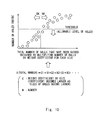
- Fig. 10 is a diagram that exemplifies the quality criterion of the cladding layer formed by the laser build-up apparatus according to the first embodiment.
- the correlation relationship between the sizes and the number of balls 18 absorbed in the melt pool 31 and the number of holes 19 that exist in the cladding layer 16 is obtained in advance.
- the sizes and the number of balls 18 absorbed in the melt pool 31 when the cladding layer 16 is formed are observed.
- the total number of balls 18 is calculated from the sizes and the number of balls 18 that have been observed.
- the total number of balls 18 means the total number of balls 18 that have been sucked and is obtained by multiplying the number of balls 18 by a weight coefficient for each size of the balls 18.
- the total number of balls 18 can be obtained, for example, from the following equation (1).
- X Total Number C 1 ⁇ N 1 + C 2 ⁇ N 2 + C 3 ⁇ N 3 + ⁇
- the symbol Ci is a weight coefficient for each size of the balls 18 and the coefficient becomes larger as the sizes of the balls 18 becomes larger.
- the symbol Ni denotes the number of balls 18.
- the total number of balls is obtained.
- the number of holes 19 that exist inside the cladding layer 16 that has been observed is obtained.
- the number of holes 19 is observed, for example, by a CT image.
- a scatter diagram in which the horizontal axis represents the total number of balls 18 and the vertical axis represents the number of holes 19 that exist inside the cladding layer 16 is created.
- the total number of balls 18 and the number of holes 19 obtained by observing some cladding layers 16 are plotted in the scatter diagram. These plots exhibit a positive correlation relationship. In this way, the correlation relationship between the sizes and the number of balls 18 and the number of holes 19 that exist in the cladding layer 16 is obtained.
- an allowable level of the holes 19 that exist in the cladding layer 16 is set to be a threshold.
- the cladding layer 16 in which the number of holes 19 is equal to or smaller than the threshold is a non-defective product.
- the cladding layer 16 in which the number of holes 19 exceeds the threshold is a defective product.
- the total number of balls 18 corresponding to the threshold is set using the correlation relationship that has been obtained.
- the cladding layer 16 in which the total number of balls 18 is equal to or smaller than the number of balls that has been set is determined to be OK, which means it is a non-defective product.
- the cladding layer in which the total number of balls 18 exceeds the number of balls that has been set is determined to be NG, which means it is a defective product.
- the determination is carried out according to the criterion of the quality of the cladding layer 16.
- the quality determination method includes the process of measuring the sizes and the number of balls 18 (ball-shaped metallic powder aggregates) absorbed in the melt pool 31 from the captured image and the process of determining the quality of the cladding layer 16 based on the sizes and the number of balls 18 that have been measured. It is possible to accurately predict the occurrence of the holes formed by the balls 18 based on the sizes and the number of balls 18 (ball-shaped metallic powder aggregates) that have been measured. It is therefore possible to accurately determine the quality of the cladding layer 16.
- Japanese Unexamined Patent Application Publication No. 09-192861 the presence or the absence of an abnormality in the cladding layer is determined by observing the intensity of light emitted from the melt pool.
- the phenomenon which causes the hole 19 to occur inside the cladding layer 16 is captured from the image of the melt pool 31 and the area around thereof while the cladding layer 16 is being formed. Accordingly, it is possible to determine the quality of the internal part of the cladding layer 19 (the presence of the large hole 19), which is difficult to achieve in the related art.
- the image-capture unit 8 is separated from the case 9.
- Fig. 11 is a configuration diagram that exemplifies a laser build-up apparatus according to a second embodiment.
- the image-capture unit 8 is separated from the case 9.
- the light emitted from the melt pool 31 and the area around thereof is not received through the laser clad head 20.
- the optical axis A1 of the laser beam 30 that illuminates the melt pool 31 and the optical axis of the light to capture the image of the melt pool 31 and the area around thereof do not coincide with each other.
- the determination is carried out based on the image captured by the image-capture unit 8. Since the other configurations are similar to those of the first embodiment, the descriptions thereof will be omitted.
- the quality determination accuracy decreases.
- a method of determining a quality of a cladding layer is a method of determining a quality of a cladding layer 16 formed by irradiating a laser beam 30 while a metallic powder 26 is being supplied, the method including: a process of capturing an image of a melt pool 31 and an area around thereof while the cladding layer 16 is being formed; a process of measuring the sizes and the number of ball-shaped metallic powder aggregates absorbed in the melt pool 31 from the image that has been captured; and a process of determining the quality of the cladding layer 16 based on the sizes and the number that have been measured.
Landscapes
- Engineering & Computer Science (AREA)
- Physics & Mathematics (AREA)
- Optics & Photonics (AREA)
- Mechanical Engineering (AREA)
- Plasma & Fusion (AREA)
- Quality & Reliability (AREA)
- Laser Beam Processing (AREA)
Abstract
Description
- This application is based upon and claims the benefit of priority from
Japanese patent application No. 2015-140329, filed on July 14, 2015 - The present invention relates to a method of determining a quality of a cladding layer and a laser build-up apparatus, and relates to, for example, a method of determining a quality of a cladding layer for a valve seat and a laser build-up apparatus for the valve seat.
- A laser cladding process (so-called a laser cladding method) that irradiates a laser beam while a metallic powder is being supplied to form a cladding layer is used, for example, to form a valve seat of a cylinder head.
-
Japanese Unexamined Patent Application Publication No. 09-192861 - The present inventors have found that holes (blow holes) are generated when excess metallic powder (excess powder) deposited at the front of the direction in which a melt pool moves aggregates, the state of the excess metallic powder becomes a semi-molten one since a laser beam comes close to it, the excess metallic powder becomes balls (ball-shaped metal aggregates) having a relatively large size, and then the balls are absorbed in the melt pool. In the apparatus disclosed in
Japanese Unexamined Patent Application Publication No. 09-192861 - The present invention has been made in order to solve the above problem and aims to provide a method of determining a quality of a cladding layer and a laser build-up apparatus capable of accurately determining the quality of the cladding layer.
- A method of determining a quality of a cladding layer according to one aspect of the present invention is a method of determining a quality of a cladding layer formed by irradiating a laser beam while a metallic powder is being supplied, the method including: a process of capturing an image of a melt pool and an area around thereof while the cladding layer is being formed; a process of measuring the sizes and the number of ball-shaped metallic powder aggregates absorbed in the melt pool from the image that has been captured; and a process of determining the quality of the cladding layer based on the sizes and the number that have been measured.
- According to this configuration, it is possible to accurately predict the occurrence of the hole due to the ball-shaped metallic powder aggregates based on the sizes and the number of the ball-shaped metallic powder aggregates that have been measured, whereby it is possible to accurately determine the quality of the cladding layer.
- Further, it is preferable that an optical axis of the laser beam that illuminates the melt pool be made coincident with an optical axis of light to capture the image of the melt pool and the area around thereof. According to this configuration, it is possible to capture the whole image of the melt pool and the area around thereof.
- A laser build-up apparatus according to one aspect of the present invention includes: a supply part that supplies a metallic powder; and a laser oscillator that outputs a laser beam, in which: a cladding layer is formed by irradiating the laser beam while the metallic power is being supplied from the supply part, the laser build-up apparatus further includes: an image-capture unit that captures an image of a melt pool and an area around thereof; and a measurement unit that measures the sizes and the number of ball-shaped metallic powder aggregates absorbed in the melt pool from the image that has been captured, and a quality of the cladding layer is determined based on the sizes and the number of the metallic powder aggregates.
- According to this configuration, it is possible to accurately predict the occurrence of the hole due to the ball-shaped metallic powder aggregates based on the sizes and the number of the ball-shaped metallic powder aggregates that have been measured, whereby it is possible to accurately determine the quality of the cladding layer.
- Further, it is preferable that a nozzle having a central axis be further included and an optical axis of the laser beam that illuminates the melt pool and an optical axis of light to capture the images of the melt pool and the area around thereof coincide with the central axis. According to this configuration, it is possible to capture the whole image of the melt pool and the area around thereof.
- According to the present invention, it is possible to provide a method of determining a quality of a cladding layer and a laser build-up apparatus capable of accurately determining the quality of the cladding layer.
- The above and other objects, features and advantages of the present invention will become more fully understood from the detailed description given hereinbelow and the accompanying drawings which are given by way of illustration only, and thus are not to be considered as limiting the present invention.
-
-
Fig. 1 is a configuration diagram that exemplifies a laser build-up apparatus according to a first embodiment; -
Fig. 2 is a cross-sectional view that exemplifies a laser clad head of the laser build-up apparatus according to the first embodiment; -
Fig. 3 is a perspective view that exemplifies a laser build-up method according to the first embodiment; -
Fig. 4 is a photo that exemplifies a melt pool and an area around thereof in the laser build-up apparatus according to the first embodiment; -
Fig. 5 is a photo that exemplifies the melt pool and the area around thereof in the laser build-up apparatus according to the first embodiment; -
Fig. 6 is a photo that exemplifies a CT image having a circular cross section when a cladding layer formed by the laser build-up apparatus according to the first embodiment is seen from a side of a combustion chamber; -
Fig. 7 is a photo that exemplifies a CT image having a cross section taken along the line A-A' ofFig. 6 ; -
Fig. 8 is a graph in which a correlation of the sizes of balls sucked into the melt pool and the presence or the absence of holes inside the cladding layer is exemplified in the laser build-up apparatus according to the first embodiment, with a horizontal axis representing the sizes of the balls sucked into the melt pool and a vertical axis representing the frequency; -
Fig. 9 is a flowchart that exemplifies a method of determining a quality of the cladding layer in the laser build-up apparatus according to the first embodiment; -
Fig. 10 is a diagram that exemplifies a quality criterion of the cladding layer formed by the laser build-up apparatus according to the first embodiment; and -
Fig. 11 is a configuration diagram that exemplifies a laser build-up apparatus according to a second embodiment. - Hereinafter, with reference to the drawings, embodiments of the present invention will be described. However, the present invention is not limited to the following embodiments. For the clarification of the description, the following description and the drawings are simplified as appropriate.
-
Fig. 1 is a configuration diagram that exemplifies a laser build-up apparatus according to a first embodiment. - Referring to
Fig. 1 , a configuration of the laser build-up apparatus according to the first embodiment will be described. A laser build-up apparatus 100 includes asupply part 1, alaser oscillator 2, acontroller 3, alaser processing part 4, animage processor 5, a measurement anddetermination unit 6, and a determinationresult display unit 7. Thelaser processing part 4 includes an image-capture unit 8, acase 9, and alaser clad head 20. - The
supply part 1 supplies a metallic powder 26. Thesupply part 1 mixes a carrier gas 25 with the metallic powder 26 and supplies the metallic powder 26 together with the carrier gas 25 to thelaser clad head 20. Further, thesupply part 1 supplies acenter gas 24 to the laserclad head 20. Thecenter gas 24 and the carrier gas 25 are, for example, each an inactive gas such as nitrogen or argon. The metallic powder 26 includes, for example, copper powder. - The
laser oscillator 2 outputs alaser beam 30. Thelaser beam 30 that is output passes through thecase 9 and the laserclad head 20 and illuminates a processing point (melt pool 31). - The
controller 3 controls supply and stop of supply of powder in thesupply part 1 and output and stop of the laser in thelaser oscillator 2. Thecontroller 3 further controls the flow rate of thecenter gas 24 and the carrier gas 25, the supply amount of the metallic powder 26, and the output of thelaser beam 30. - A
beam splitter 41 is provided inside thecase 9 of thelaser processing part 4. Thebeam splitter 41 reflects a part of the light that has been input and transmits the other part of the light. Thebeam splitter 41 transmits a part of thelaser beam 30 from thelaser oscillator 2 to the side of the processing point (melt pool 31) and reflects the other part of the light from themelt pool 31 and the area around thereof to the side of the image-capture unit 8. - The
laser clad head 20 is attached to thecase 9. Thelaser clad head 20 emits thelaser beam 30 that has transmitted thebeam splitter 41 to the processing point. Further, the laserclad head 20 discharges the metallic powder 26 that has been supplied to the processing point. In this way, by irradiating thelaser beam 30 while the metallic powder 26 is being supplied, acladding layer 16 is formed. Themelt pool 31 is formed on the surface of thecladding layer 16 opposed to the laserclad head 20. The laserclad head 20 delivers the light emitted from themelt pool 31 and the area around thereof to thebeam splitter 41. -
Fig. 2 is a cross-sectional view that exemplifies the laser clad head of the laser build-up apparatus according to the first embodiment. - As shown in
Fig. 2 , the laserclad head 20 includes aninner nozzle 21, anouter nozzle 22, and a rawmaterial supply pipe 23. Specifically, the laser cladhead 20 has a coaxial double-tube structure including theinner nozzle 21 and theouter nozzle 22 both having an optical axis A1 of thelaser beam 30 as a central axis. - The
laser beam 30 is emitted from theinner nozzle 21. On the other hand, light to capture the image of themelt pool 31 and the area around thereof is input to theinner nozzle 21. Accordingly, the optical axis A1 of thelaser beam 30 that illuminates themelt pool 31 and the optical axis of the light to capture the image of themelt pool 31 and the area around thereof coincide with each other in the laser cladhead 20. Thecenter gas 24 is discharged from theinner nozzle 21. Further, the carrier gas 25 and the metallic powder 26 supplied via the rawmaterial supply pipe 23 are discharged from between theinner nozzle 21 and theouter nozzle 22. That is, the optical axis A1 of thelaser beam 30 that illuminates themelt pool 31 and the optical axis of the light to capture the image of themelt pool 31 and the area around thereof coincide with the central axis of theinner nozzle 21 and theouter nozzle 22. - By integrating the functions of irradiating the
laser beam 30 and supplying thecenter gas 24, the carrier gas 25, and the metallic powder 26, the size of thelaser processing part 4 can be reduced. Further, since the optical axis of thelaser beam 30 that illuminates themelt pool 31 and the optical axis of the light to capture the image of themelt pool 31 and the area around thereof coincide with each other in the laser cladhead 20, the whole image of themelt pool 31 and the area around thereof can be captured. - As shown in
Fig. 1 , the image-capture unit 8 is attached to thecase 9. The light emitted from themelt pool 31 and the area around thereof is reflected by thebeam splitter 41 in thecase 9 and then the image-capture unit 8 receives the reflected light. The image-capture unit 8 therefore captures the image of themelt pool 31 and the area around thereof. The image-capture unit 8 is, for example, a Charge-Coupled Device (CCD) camera. - The
image processor 5 processes the image captured by the image-capture unit 8. For example, theimage processor 5 creates a black-white contrast on the image by changing the intensity of brightness. - The measurement and
determination unit 6 performs measurement and determination based on the image that has been processed. Accordingly, the measurement anddetermination unit 6 measures the sizes and the number of ball-shaped metallic powder aggregates (balls) absorbed in themelt pool 31 from the image that has been captured. The measurement anddetermination unit 6 further measures the number of holes in thecladding layer 16. The measurement anddetermination unit 6 further calculates the area of the balls for each contrast created by theimage processor 5. - The determination
result display unit 7 displays the image that has been captured and the image that has been processed. The determinationresult display unit 7 further displays the sizes and the number of balls that have been measured. The determinationresult display unit 7 further displays the number of holes. The determinationresult display unit 7 further displays the result of determining the quality of thecladding layer 16 that has been measured. The determinationresult display unit 7 is, for example, a Cathode Ray Tube (CRT). -
Fig. 3 is a perspective view that exemplifies a laser build-up method according to the first embodiment. - Referring to
Fig. 3 , a cylinder head roughly formedmaterial 10 will be described. The cylinder head roughly formedmaterial 10 is casting formed of, for example, cast iron or aluminum alloy. The cylinder head roughly formedmaterial 10 includes a plurality ofcombustion chambers 11. Each of thecombustion chambers 11 includes aninlet port 12 and anoutlet port 13. In each of theinlet port 12 and theoutlet port 13, an annular counter sunkgroove 15 that surrounds anopening 14 is formed along the periphery of theopening 14 on the side of thecombustion chamber 11. The counter sunkgroove 15 is formed by machine processing. - The cylinder head roughly formed
material 10 shown inFig. 3 is for 4-cylinder, 16-valve engines and includes twoinlet ports 12 and twooutlet ports 13 in each of the fourcombustion chambers 11. As a matter of course, the number ofcombustion chambers 11, the number ofinlet ports 12, and the number ofoutlet ports 13 are not limited to those shown in the example ofFig. 3 and are determined as appropriate. - Next, an operation of the laser build-up
apparatus 100 according to this embodiment will be described. Regarding this operation, the method of forming thecladding layer 16, the method of capturing the image of themelt pool 31, the method of measuring theball 18 in the image that has been captured, and the method of determining the quality of thecladding layer 16 will be separately explained. Fist, the method of forming thecladding layer 16 will be described. - As shown in
Fig. 1 , thecontroller 3 causes thesupply part 1 to mix the carrier gas 25 with the metallic powder 26. Thecontroller 3 further causes thelaser oscillator 2 to start operation. Thecontroller 3 controls thesupply part 1 and causes thesupply part 1 to supply the carrier gas 25 in which thecenter gas 24 and the metallic powder 26 are mixed to the laser cladhead 20. At the same time, thecontroller 3 controls thelaser oscillator 2 and causes thelaser oscillator 2 to emit thelaser beam 30 to thecase 9. Thecontroller 3 matches the timing of the supply of the metallic powder 26 with the emission of thelaser beam 30. Thelaser beam 30 emitted to thecase 9 passes through thecase 9 and reaches thebeam splitter 41. Thebeam splitter 41 allows a part of thelaser beam 30 to pass therethrough. - As shown in
Figs. 1 and2 , thecenter gas 24 supplied to the laser cladhead 20 is discharged from theinner nozzle 21. The carrier gas 25 and the metallic powder 26 are discharged to the inside of the counter sunkgroove 15 from between theinner nozzle 21 and theouter nozzle 22. On the other hand, thelaser beam 30 that has been transmitted through thebeam splitter 41 passes through theinner nozzle 21 of the laser cladhead 20 and illuminates the processing point (melt pool 31) inside the counter sunkgroove 15. - As stated above, the laser build-up
apparatus 100 irradiates the laser beam 30 (optical axis A1) while supplying the metallic powder 26 to the counter sunkgroove 15 from thesupply part 1. Accordingly, the metallic powder 26 is melted and solidified inside the counter sunkgroove 15 and thecladding layer 16 for the valve seat is formed. Themelt pool 31 is formed on the surface of thecladding layer 16 opposed to thelaser beam 30. - As shown in
Fig. 3 , the laser cladhead 20 is rotated about a central axis A2 of the annular counter sunkgroove 15. In this way, thecladding layer 16 is formed along the full circumference of the counter sunkgroove 15. The direction in which the laser cladhead 20 is moved is referred to as aprocessing direction 17. Further, the central axis A2 is an axis that is vertical to two diameters that are perpendicular to each other in the circle formed by the annular form of the counter sunkgroove 15 and passes through a center O, which is the center of the circle. - Next, the method of capturing the image of the
melt pool 31 will be described. - As shown in
Fig. 1 , among the light beams emitted from themelt pool 31 and the area around thereof, the light to capture the image passes through the laser cladhead 20 and reaches thebeam splitter 41. In this way, the optical axis of thelaser beam 30 that illuminates themelt pool 31 and the optical axis of the light to capture the image of themelt pool 31 and the area around thereof are made coincident with each other in the laser cladhead 20. - The light to capture the image includes, besides the light emitted from the
melt pool 31, light emitted and reflected from the metallic powder aggregates that exist near themelt pool 31. Thebeam splitter 41 reflects a part of the light from themelt pool 31 and the area around thereof. The reflected light reaches the image-capture unit 8. The image-capture unit 8 therefore captures the image of themelt pool 31 and the area around thereof while thecladding layer 16 is being formed. The image captured by the image-capture unit 8 is processed by theimage processor 5. -
Figs. 4 and5 are photos that exemplify the melt pool and the area around thereof in the laser build-up apparatus according to the first embodiment. - As shown in
Fig. 4 , themelt pool 31 is formed on the tip of thecladding layer 16 in the process of forming thecladding layer 16. There is no ball 18 (not shown) and no metallic powder aggregate at the front of theprocessing direction 17 of themelt pool 31. Theball 18 means the metallic powder aggregates that form a ball shape. - On the other hand, as shown in
Fig. 5 , there is aball 18 at the front of theprocessing direction 17 of themelt pool 31. Theball 18 causes an internal defect of thecladding layer 16. In this way, the image-capture unit 8 captures the image of themelt pool 31 and the area around thereof while thecladding layer 16 is being formed. Further, the image-capture unit 8 captures the image of the ball-shaped metallic powder aggregates (balls 18) absorbed in themelt pool 31. -
Fig. 6 is a photo that exemplifies a CT image having a circular cross section when the cladding layer formed by the laser build-up apparatus according to the first embodiment is seen from the side of the combustion chamber. - As shown in
Fig. 6 , thehole 19 is observed (in the circle 19) in the circular cross section when thecladding layer 16 is seen from the side of thecombustion chamber 11. The part in which thehole 19 was observed corresponds to the part that has sucked the ball 18 (ball sucking part 27) when themelt pool 31 was observed. On the other hand, the part in which thehole 19 was observed does not necessarily correspond to the part that has sucked the metallic powder aggregates (suckingpart 32 of the metallic powder aggregates) when themelt pool 31 was observed. -
Fig. 7 is a photo that exemplifies a CT image having a cross section taken along the line A-A' shown inFig. 6 . - As shown in
Fig. 7 , in the part in which thehole 19 was observed on the CT image having a circular cross section of thecladding layer 16, thehole 19 is observed. In this way, in the laser build-upapparatus 100 according to this embodiment, it is possible to make the part in which thehole 19 was observed correspond to theball sucking part 27. - Next, the method of measuring the
ball 18 on the captured image will be described. - As shown in
Fig. 1 , the image processed by theimage processor 5 is transmitted to the measurement anddetermination unit 6. The measurement anddetermination unit 6 measures the sizes and the number of balls 18 (ball-shaped metallic powder aggregates) absorbed in themelt pool 31 from the captured image. The results are displayed on the determinationresult display unit 7. The quality of thecladding layer 16 is determined based on the sizes and the number of metallic powder aggregates. -
Fig. 8 is a graph that exemplifies a correlation of the sizes of the balls sucked into the melt pool and the presence or the absence of the hole inside the cladding layer in the laser build-up apparatus according to the first embodiment. In this graph, the horizontal axis represents the sizes of the balls sucked into the melt pool and the vertical axis represents the frequency. The white column presents the summary of the results of thecladding layer 16 in which thehole 19 was not observed. On the other hand, the black column presents the summary of the results of thecladding layer 16 in which thehole 19 was observed. - As shown in
Fig. 8 , in the cladding layer 16 (white column) in which thehole 19 was not observed, there are 35balls 18 having the size of 1.0 mmφ or smaller, 78balls 18 having the size of 1.1 to 1.5 mmφ, and 4balls 18 having the size of 1.6 to 2.0 mmφ. On the other hand, in the cladding layer 16 (black column) in which thehole 19 was observed, there is noball 18 having the size of 1.0 mmφ or smaller, 20balls 18 having the size of 1.1 to 1.5 mmφ, and 10balls 18 having the size of 1.6 to 2.0 mmφ. In this way, the number ofballs 18 having the size of 1.6 to 2.0 mmφ in the black column (thecladding layer 16 in which thehole 19 was observed) is larger than the number of balls in the white column (thecladding layer 16 in which thehole 19 was not observed). That is, the rate of occurrence of the hole increases as the sizes of theballs 18 increase. - Next, the method of determining the quality of the
cladding layer 16 will be described. -
Fig. 9 is a flowchart that exemplifies the method of determining the quality of the cladding layer in the laser build-up apparatus according to the first embodiment. - As shown in Step S1 of
Fig. 9 , first, the measurement anddetermination unit 6 receives an image of the processing point (melt pool 31) processed by theimage processor 5. The measurement anddetermination unit 6 receives, for example, an image in which black-white contrast is created according to the brightness. - Next, as shown in Step S2, the sizes of the
balls 18 observed at the front of the processing direction of themelt pool 31 are measured and the number ofballs 18 is counted. The measurement of the sizes of the balls is performed, for example, by measuring the area of the contrasted image. - Next, as shown in Step S3, it is determined whether the sizes of the
balls 18 that have been measured and the number ofballs 18 that has been counted are smaller than thresholds in the quality criterion. When the sizes of theballs 18 that have been measured and the number ofballs 18 that has been counted are smaller than the thresholds (Yes), the process goes to Step S4. When the sizes of theballs 18 and the number ofballs 18 are larger than the thresholds (No), the process goes to Step S5. - Next, when the sizes of the
balls 18 that have been measured and the number ofballs 18 that has been counted are smaller than the thresholds as shown in Step S4, thecladding layer 16 that has been formed is determined to be OK, which means it is a non-defective product. The process then goes to Step S6. - On the other hand, when the sizes of the
balls 18 that have been measured and the number ofballs 18 that has been counted are larger than the thresholds as shown in Step S5, thecladding layer 16 that has been formed is determined to be NG, which means it is a defective product. The process then goes to Step S6. - Next, as shown in Step S6, the result of the determination is output. The determination result is output, for example, to the determination
result display unit 7. - In this way, the quality of the
cladding layer 16 is measured based on the sizes and the number ofballs 18 that have been measured. - Next, one example of the quality criterion in the method of determining the quality of the
cladding layer 16 will be described. -
Fig. 10 is a diagram that exemplifies the quality criterion of the cladding layer formed by the laser build-up apparatus according to the first embodiment. - As shown in
Fig. 10 , the correlation relationship between the sizes and the number ofballs 18 absorbed in themelt pool 31 and the number ofholes 19 that exist in thecladding layer 16 is obtained in advance. In order to obtain the correlation relationship, first, the sizes and the number ofballs 18 absorbed in themelt pool 31 when thecladding layer 16 is formed are observed. Then the total number ofballs 18 is calculated from the sizes and the number ofballs 18 that have been observed. The total number ofballs 18 means the total number ofballs 18 that have been sucked and is obtained by multiplying the number ofballs 18 by a weight coefficient for each size of theballs 18. The total number ofballs 18 can be obtained, for example, from the following equation (1).
- The symbol Ci is a weight coefficient for each size of the
balls 18 and the coefficient becomes larger as the sizes of theballs 18 becomes larger. The symbol Ni denotes the number ofballs 18. - In this way, the total number of balls is obtained. Next, the number of
holes 19 that exist inside thecladding layer 16 that has been observed is obtained. The number ofholes 19 is observed, for example, by a CT image. Then a scatter diagram in which the horizontal axis represents the total number ofballs 18 and the vertical axis represents the number ofholes 19 that exist inside thecladding layer 16 is created. The total number ofballs 18 and the number ofholes 19 obtained by observing some cladding layers 16 are plotted in the scatter diagram. These plots exhibit a positive correlation relationship. In this way, the correlation relationship between the sizes and the number ofballs 18 and the number ofholes 19 that exist in thecladding layer 16 is obtained. - Next, the method of determining the quality of the
cladding layer 16 using this correlation relationship will be described. - One factor to determine the quality of the
cladding layer 16 is the number ofholes 19 that exist inside thecladding layer 16. First, as shown inFig. 10 , an allowable level of theholes 19 that exist in thecladding layer 16 is set to be a threshold. Thecladding layer 16 in which the number ofholes 19 is equal to or smaller than the threshold is a non-defective product. Thecladding layer 16 in which the number ofholes 19 exceeds the threshold is a defective product. Next, the total number ofballs 18 corresponding to the threshold is set using the correlation relationship that has been obtained. Thecladding layer 16 in which the total number ofballs 18 is equal to or smaller than the number of balls that has been set is determined to be OK, which means it is a non-defective product. On the other hand, the cladding layer in which the total number ofballs 18 exceeds the number of balls that has been set is determined to be NG, which means it is a defective product. - That is, it is determined that the quality of the
cladding layer 16 becomes higher as the sizes and the number ofballs 18 that have been sucked into themelt pool 31 become smaller. In contrast, it is determined that the quality of thecladding layer 16 becomes lower as the sizes and the number ofballs 18 that have been sucked into themelt pool 31 become larger. In this way, the determination is carried out according to the criterion of the quality of thecladding layer 16. - Next, effects of the quality determination method using the laser build-up apparatus according to this embodiment will be described.
- The quality determination method according to this embodiment includes the process of measuring the sizes and the number of balls 18 (ball-shaped metallic powder aggregates) absorbed in the
melt pool 31 from the captured image and the process of determining the quality of thecladding layer 16 based on the sizes and the number ofballs 18 that have been measured. It is possible to accurately predict the occurrence of the holes formed by theballs 18 based on the sizes and the number of balls 18 (ball-shaped metallic powder aggregates) that have been measured. It is therefore possible to accurately determine the quality of thecladding layer 16. - Further, in this embodiment, it is possible to determine the quality of the internal part of the
cladding layer 16 which cannot be detected from a visual inspection in real time and in a non-destructive manner. - In
Japanese Unexamined Patent Application Publication No. 09-192861 Japanese Unexamined Patent Application Publication No. 09-192861 - Unlike
Japanese Unexamined Patent Application Publication No. 09-192861 hole 19 to occur inside thecladding layer 16 is captured from the image of themelt pool 31 and the area around thereof while thecladding layer 16 is being formed. Accordingly, it is possible to determine the quality of the internal part of the cladding layer 19 (the presence of the large hole 19), which is difficult to achieve in the related art. - Next, a laser build-up method according to a second embodiment will be described. In this embodiment, the image-
capture unit 8 is separated from thecase 9. -
Fig. 11 is a configuration diagram that exemplifies a laser build-up apparatus according to a second embodiment. - As shown in
Fig. 11 , in a laser build-upapparatus 200, the image-capture unit 8 is separated from thecase 9. The light emitted from themelt pool 31 and the area around thereof is not received through the laser cladhead 20. As a result, the optical axis A1 of thelaser beam 30 that illuminates themelt pool 31 and the optical axis of the light to capture the image of themelt pool 31 and the area around thereof do not coincide with each other. The determination is carried out based on the image captured by the image-capture unit 8. Since the other configurations are similar to those of the first embodiment, the descriptions thereof will be omitted. - In the laser build-up
apparatus 200 according to this embodiment, it is difficult to capture the whole image of themelt pool 31 and the area around thereof. Therefore, compared to the configuration in which the image is taken from the direction coaxial to the direction of thelaser beam 30 as in the first embodiment, the quality determination accuracy decreases. However, there is a large freedom with regard to selecting the part to be captured. It is therefore possible to capture the image of a desired part. - While the embodiments of the apparatus of determining the quality of the cladding layer and the laser build-up apparatus according to the present invention have been described above, the present invention is not limited to the above configurations and may be changed without departing from the spirit of the present invention.
- From the invention thus described, it will be obvious that the embodiments of the invention may be varied in many ways. Such variations are not to be regarded as a departure from the spirit and scope of the invention, and all such modifications as would be obvious to one skilled in the art are intended for inclusion within the scope of the following claims.
- A method of determining a quality of a cladding layer according to one aspect of the present invention is a method of determining a quality of a
cladding layer 16 formed by irradiating alaser beam 30 while a metallic powder 26 is being supplied, the method including: a process of capturing an image of amelt pool 31 and an area around thereof while thecladding layer 16 is being formed; a process of measuring the sizes and the number of ball-shaped metallic powder aggregates absorbed in themelt pool 31 from the image that has been captured; and a process of determining the quality of thecladding layer 16 based on the sizes and the number that have been measured.
Claims (4)
- A method of determining a quality of a cladding layer (16) formed by irradiating a laser beam (30) while a metallic powder (26) is being supplied, the method comprising:a process of capturing an image of a melt pool (31) and an area around thereof while the cladding layer (16) is being formed;a process of measuring the sizes and the number of ball-shaped metallic powder aggregates absorbed in the melt pool (31) from the image that has been captured; anda process of determining the quality of the cladding layer (16) based on the sizes and the number that have been measured.
- The method of determining the quality of the cladding (16) layer according to Claim 1, wherein an optical axis of the laser beam (30) that illuminates the melt pool (31) is made coincident with an optical axis of light to capture the image of the melt pool (31) and the area around thereof.
- A laser build-up apparatus (100) comprising:a supply part (1) that supplies a metallic powder (26); anda laser oscillator (2) that outputs a laser beam (30), wherein:a cladding layer (16) is formed by irradiating the laser beam (30) while the metallic power (26) is being supplied from the supply part (1),the laser build-up apparatus (100) further comprises:an image-capture (8) unit that captures an image of a melt pool (31) and an area around thereof; anda measurement unit (6) that measures the sizes and the number of ball-shaped metallic powder aggregates absorbed in the melt pool (31) from the image that has been captured, anda quality of the cladding layer (16) is determined based on the sizes and the number of the metallic powder aggregates.
- The laser build-up apparatus according to Claim 3, further comprising a nozzle having a central axis, wherein an optical axis of the laser beam (30) that illuminates the melt pool (31) and an optical axis of light to capture the image of the melt pool (31) and the area around thereof coincide with the central axis.
Applications Claiming Priority (1)
| Application Number | Priority Date | Filing Date | Title |
|---|---|---|---|
| JP2015140329A JP6241458B2 (en) | 2015-07-14 | 2015-07-14 | Method for determining quality of overlay layer and laser overlay apparatus |
Publications (2)
| Publication Number | Publication Date |
|---|---|
| EP3117947A1 true EP3117947A1 (en) | 2017-01-18 |
| EP3117947B1 EP3117947B1 (en) | 2018-02-28 |
Family
ID=56411383
Family Applications (1)
| Application Number | Title | Priority Date | Filing Date |
|---|---|---|---|
| EP16175404.9A Not-in-force EP3117947B1 (en) | 2015-07-14 | 2016-06-21 | Method of determining quality of cladding layer and laser build-up apparatus |
Country Status (3)
| Country | Link |
|---|---|
| US (1) | US10286495B2 (en) |
| EP (1) | EP3117947B1 (en) |
| JP (1) | JP6241458B2 (en) |
Families Citing this family (9)
| Publication number | Priority date | Publication date | Assignee | Title |
|---|---|---|---|---|
| JP2015165605A (en) * | 2013-11-26 | 2015-09-17 | 株式会社Nttドコモ | User terminal, radio base station, and radio communication method |
| JP6210093B2 (en) * | 2015-07-16 | 2017-10-11 | トヨタ自動車株式会社 | Laser overlaying method |
| US10828837B2 (en) | 2018-12-13 | 2020-11-10 | General Electric Company | Method for melt pool monitoring using algebraic connectivity |
| US10828836B2 (en) | 2018-12-13 | 2020-11-10 | General Electric Company | Method for melt pool monitoring |
| US11020907B2 (en) | 2018-12-13 | 2021-06-01 | General Electric Company | Method for melt pool monitoring using fractal dimensions |
| US11285671B2 (en) | 2018-12-13 | 2022-03-29 | General Electric Company | Method for melt pool monitoring using Green's theorem |
| US10894364B2 (en) | 2018-12-13 | 2021-01-19 | General Electric Company | Method for melt pool monitoring using geometric length |
| US20200248315A1 (en) * | 2019-02-04 | 2020-08-06 | Jtekt Corporation | Laser clad layer forming method and laser cladding device |
| US11338390B2 (en) * | 2019-02-12 | 2022-05-24 | Lawrence Livermore National Security, Llc | Two-color high speed thermal imaging system for laser-based additive manufacturing process monitoring |
Citations (4)
| Publication number | Priority date | Publication date | Assignee | Title |
|---|---|---|---|---|
| JPH09192861A (en) | 1996-01-11 | 1997-07-29 | Nissan Motor Co Ltd | Quality assurance method and quality assurance device for meat filling |
| JP2000202626A (en) * | 1999-01-20 | 2000-07-25 | Daido Steel Co Ltd | Al-based structure with hard overlay and composite material for overlay used therefor |
| JP2008188648A (en) * | 2007-02-06 | 2008-08-21 | Toyota Motor Corp | Laser cladding processing method and apparatus |
| DE102007032190A1 (en) * | 2007-07-11 | 2009-01-15 | Daimler Ag | Method for treating the surface of a workpiece using heat comprises analyzing image signals in pixels and identifying an object based on shade gradients from which a geometric property can be determined |
Family Cites Families (17)
| Publication number | Priority date | Publication date | Assignee | Title |
|---|---|---|---|---|
| JP3142401B2 (en) * | 1992-10-16 | 2001-03-07 | トヨタ自動車株式会社 | Laser clad processing abnormality judgment method |
| JP2002048718A (en) | 2000-07-31 | 2002-02-15 | Nissan Motor Co Ltd | Quality judgment method of clad layer in laser clad processing |
| JP3589289B2 (en) * | 2000-09-22 | 2004-11-17 | 日産自動車株式会社 | Quality determination method and quality determination apparatus for laser cladding processing |
| EP1340583A1 (en) * | 2002-02-20 | 2003-09-03 | ALSTOM (Switzerland) Ltd | Method of controlled remelting of or laser metal forming on the surface of an article |
| US20080314878A1 (en) * | 2007-06-22 | 2008-12-25 | General Electric Company | Apparatus and method for controlling a machining system |
| JP5608314B2 (en) * | 2007-08-17 | 2014-10-15 | 日産自動車株式会社 | Laser cladding processing apparatus and laser cladding processing method |
| US20100140236A1 (en) * | 2008-12-04 | 2010-06-10 | General Electric Company | Laser machining system and method |
| DE102009004661A1 (en) * | 2009-01-12 | 2010-07-15 | Rolls-Royce Deutschland Ltd & Co Kg | Apparatus for repairing the blades of BLISK drums by means of laser beam welding |
| JP5410129B2 (en) * | 2009-03-25 | 2014-02-05 | 本田技研工業株式会社 | Internal inspection method of laser cladding valve seat |
| DE102010018686B4 (en) * | 2010-04-22 | 2017-08-17 | Fraunhofer-Gesellschaft zur Förderung der angewandten Forschung e.V. | Apparatus and method for laser cladding with powdered filler material |
| FR2970887B1 (en) * | 2011-02-01 | 2013-12-20 | Snecma | SINKING DEVICE AND LASER FUSION COMPRISING A INDUCED POWDER HEATING MEANS |
| JP2012192436A (en) * | 2011-03-16 | 2012-10-11 | Osaka Municipal Technical Research Institute | Laser cladding method |
| US20150177158A1 (en) * | 2013-12-13 | 2015-06-25 | General Electric Company | Operational performance assessment of additive manufacturing |
| JP5929935B2 (en) * | 2014-01-17 | 2016-06-08 | トヨタ自動車株式会社 | Quality control method and laser cladding processing apparatus in laser cladding processing |
| US10112262B2 (en) * | 2014-10-28 | 2018-10-30 | General Electric Company | System and methods for real-time enhancement of build parameters of a component |
| US10632566B2 (en) * | 2014-12-02 | 2020-04-28 | Product Innovation and Engineering L.L.C. | System and method for controlling the input energy from an energy point source during metal processing |
| CN107206495B (en) * | 2015-01-29 | 2019-07-02 | 奥科宁克有限公司 | Method for creating a 3D volumetric mass model |
-
2015
- 2015-07-14 JP JP2015140329A patent/JP6241458B2/en active Active
-
2016
- 2016-06-15 US US15/183,423 patent/US10286495B2/en not_active Expired - Fee Related
- 2016-06-21 EP EP16175404.9A patent/EP3117947B1/en not_active Not-in-force
Patent Citations (4)
| Publication number | Priority date | Publication date | Assignee | Title |
|---|---|---|---|---|
| JPH09192861A (en) | 1996-01-11 | 1997-07-29 | Nissan Motor Co Ltd | Quality assurance method and quality assurance device for meat filling |
| JP2000202626A (en) * | 1999-01-20 | 2000-07-25 | Daido Steel Co Ltd | Al-based structure with hard overlay and composite material for overlay used therefor |
| JP2008188648A (en) * | 2007-02-06 | 2008-08-21 | Toyota Motor Corp | Laser cladding processing method and apparatus |
| DE102007032190A1 (en) * | 2007-07-11 | 2009-01-15 | Daimler Ag | Method for treating the surface of a workpiece using heat comprises analyzing image signals in pixels and identifying an object based on shade gradients from which a geometric property can be determined |
Also Published As
| Publication number | Publication date |
|---|---|
| US20170014953A1 (en) | 2017-01-19 |
| US10286495B2 (en) | 2019-05-14 |
| JP6241458B2 (en) | 2017-12-06 |
| JP2017019002A (en) | 2017-01-26 |
| EP3117947B1 (en) | 2018-02-28 |
Similar Documents
| Publication | Publication Date | Title |
|---|---|---|
| EP3117947B1 (en) | Method of determining quality of cladding layer and laser build-up apparatus | |
| US10646961B2 (en) | Laser-machining device | |
| JP6687125B2 (en) | Method for evaluating slag volume on molten metal surface | |
| CN108778606A (en) | Fire check identification in laser welding | |
| CN105531070A (en) | Device and method for determining laser weld quality | |
| SE521787C2 (en) | Device and method for controlling a welding area, arrangement and method for controlling a welding operation, computer program and computer program product | |
| US11007720B2 (en) | Three-dimensional laminating and shaping apparatus, control method of three-dimensional laminating and shaping apparatus, and control program of three-dimensional laminating and shaping apparatus | |
| WO2011024904A1 (en) | Laser welding quality determination method and quality determination device | |
| JP5929935B2 (en) | Quality control method and laser cladding processing apparatus in laser cladding processing | |
| JP6121016B1 (en) | Processing nozzle inspection apparatus and method in laser processing machine | |
| JP2011000642A (en) | Welded state monitoring device and method | |
| JP2017060968A (en) | Image processing apparatus, image processing method, laser or TIG welding apparatus, and laser or TIG welding apparatus control method | |
| WO2022244383A1 (en) | Apparatus for detecting positions of seam portion and heated portion in welded steel pipe, equipment for manufacturing welded steel pipe, method for detecting positions of seam portion and heated portion in welded steel pipe, method for manufacturing welded steel pipe, and method for managing quality of welded steel pipe | |
| JP2016224069A (en) | Surface defect detection method and surface defect detection apparatus | |
| JP2004104727A (en) | Smoke detection device | |
| Deisenroth et al. | Effects of shield gas flow on meltpool variability and signature in scanned laser melting | |
| JP2020069518A (en) | Welding monitoring device and welding monitoring method | |
| JP2018063144A (en) | Method and device for inspecting oil film | |
| JP6547652B2 (en) | Laser buildup apparatus and laser buildup method | |
| KR101309649B1 (en) | Apparatus for measuring amount of wear and tear for refractory in tapping hole sleeve of converter and method for the same | |
| JP7477350B2 (en) | Welding observation device and welding system | |
| JP2007330987A (en) | Apparatus and method for analyzing welding condition using weld zone visualizing apparatus | |
| JP7571874B2 (en) | Flame Atomic Absorption Spectrophotometer | |
| JP2013107127A (en) | Device and method for detecting scarfing abnormality | |
| JP2020003276A (en) | Oil detector and method for detecting oil |
Legal Events
| Date | Code | Title | Description |
|---|---|---|---|
| PUAI | Public reference made under article 153(3) epc to a published international application that has entered the european phase |
Free format text: ORIGINAL CODE: 0009012 |
|
| 17P | Request for examination filed |
Effective date: 20160621 |
|
| AK | Designated contracting states |
Kind code of ref document: A1 Designated state(s): AL AT BE BG CH CY CZ DE DK EE ES FI FR GB GR HR HU IE IS IT LI LT LU LV MC MK MT NL NO PL PT RO RS SE SI SK SM TR |
|
| AX | Request for extension of the european patent |
Extension state: BA ME |
|
| GRAP | Despatch of communication of intention to grant a patent |
Free format text: ORIGINAL CODE: EPIDOSNIGR1 |
|
| RIC1 | Information provided on ipc code assigned before grant |
Ipc: B23K 31/12 20060101ALI20170823BHEP Ipc: B23K 26/34 20140101ALI20170823BHEP Ipc: B23K 26/03 20060101AFI20170823BHEP |
|
| INTG | Intention to grant announced |
Effective date: 20170918 |
|
| GRAS | Grant fee paid |
Free format text: ORIGINAL CODE: EPIDOSNIGR3 |
|
| GRAA | (expected) grant |
Free format text: ORIGINAL CODE: 0009210 |
|
| AK | Designated contracting states |
Kind code of ref document: B1 Designated state(s): AL AT BE BG CH CY CZ DE DK EE ES FI FR GB GR HR HU IE IS IT LI LT LU LV MC MK MT NL NO PL PT RO RS SE SI SK SM TR |
|
| REG | Reference to a national code |
Ref country code: GB Ref legal event code: FG4D Ref country code: CH Ref legal event code: EP |
|
| REG | Reference to a national code |
Ref country code: AT Ref legal event code: REF Ref document number: 973590 Country of ref document: AT Kind code of ref document: T Effective date: 20180315 |
|
| REG | Reference to a national code |
Ref country code: IE Ref legal event code: FG4D |
|
| REG | Reference to a national code |
Ref country code: DE Ref legal event code: R096 Ref document number: 602016001722 Country of ref document: DE |
|
| REG | Reference to a national code |
Ref country code: FR Ref legal event code: PLFP Year of fee payment: 3 |
|
| REG | Reference to a national code |
Ref country code: NL Ref legal event code: MP Effective date: 20180228 |
|
| REG | Reference to a national code |
Ref country code: LT Ref legal event code: MG4D |
|
| REG | Reference to a national code |
Ref country code: AT Ref legal event code: MK05 Ref document number: 973590 Country of ref document: AT Kind code of ref document: T Effective date: 20180228 |
|
| PG25 | Lapsed in a contracting state [announced via postgrant information from national office to epo] |
Ref country code: ES Free format text: LAPSE BECAUSE OF FAILURE TO SUBMIT A TRANSLATION OF THE DESCRIPTION OR TO PAY THE FEE WITHIN THE PRESCRIBED TIME-LIMIT Effective date: 20180228 Ref country code: NL Free format text: LAPSE BECAUSE OF FAILURE TO SUBMIT A TRANSLATION OF THE DESCRIPTION OR TO PAY THE FEE WITHIN THE PRESCRIBED TIME-LIMIT Effective date: 20180228 Ref country code: LT Free format text: LAPSE BECAUSE OF FAILURE TO SUBMIT A TRANSLATION OF THE DESCRIPTION OR TO PAY THE FEE WITHIN THE PRESCRIBED TIME-LIMIT Effective date: 20180228 Ref country code: HR Free format text: LAPSE BECAUSE OF FAILURE TO SUBMIT A TRANSLATION OF THE DESCRIPTION OR TO PAY THE FEE WITHIN THE PRESCRIBED TIME-LIMIT Effective date: 20180228 Ref country code: NO Free format text: LAPSE BECAUSE OF FAILURE TO SUBMIT A TRANSLATION OF THE DESCRIPTION OR TO PAY THE FEE WITHIN THE PRESCRIBED TIME-LIMIT Effective date: 20180528 Ref country code: FI Free format text: LAPSE BECAUSE OF FAILURE TO SUBMIT A TRANSLATION OF THE DESCRIPTION OR TO PAY THE FEE WITHIN THE PRESCRIBED TIME-LIMIT Effective date: 20180228 Ref country code: CY Free format text: LAPSE BECAUSE OF FAILURE TO SUBMIT A TRANSLATION OF THE DESCRIPTION OR TO PAY THE FEE WITHIN THE PRESCRIBED TIME-LIMIT Effective date: 20180228 |
|
| PG25 | Lapsed in a contracting state [announced via postgrant information from national office to epo] |
Ref country code: LV Free format text: LAPSE BECAUSE OF FAILURE TO SUBMIT A TRANSLATION OF THE DESCRIPTION OR TO PAY THE FEE WITHIN THE PRESCRIBED TIME-LIMIT Effective date: 20180228 Ref country code: SE Free format text: LAPSE BECAUSE OF FAILURE TO SUBMIT A TRANSLATION OF THE DESCRIPTION OR TO PAY THE FEE WITHIN THE PRESCRIBED TIME-LIMIT Effective date: 20180228 Ref country code: GR Free format text: LAPSE BECAUSE OF FAILURE TO SUBMIT A TRANSLATION OF THE DESCRIPTION OR TO PAY THE FEE WITHIN THE PRESCRIBED TIME-LIMIT Effective date: 20180529 Ref country code: BG Free format text: LAPSE BECAUSE OF FAILURE TO SUBMIT A TRANSLATION OF THE DESCRIPTION OR TO PAY THE FEE WITHIN THE PRESCRIBED TIME-LIMIT Effective date: 20180528 Ref country code: RS Free format text: LAPSE BECAUSE OF FAILURE TO SUBMIT A TRANSLATION OF THE DESCRIPTION OR TO PAY THE FEE WITHIN THE PRESCRIBED TIME-LIMIT Effective date: 20180228 Ref country code: AT Free format text: LAPSE BECAUSE OF FAILURE TO SUBMIT A TRANSLATION OF THE DESCRIPTION OR TO PAY THE FEE WITHIN THE PRESCRIBED TIME-LIMIT Effective date: 20180228 |
|
| REG | Reference to a national code |
Ref country code: DE Ref legal event code: R084 Ref document number: 602016001722 Country of ref document: DE |
|
| PG25 | Lapsed in a contracting state [announced via postgrant information from national office to epo] |
Ref country code: IT Free format text: LAPSE BECAUSE OF FAILURE TO SUBMIT A TRANSLATION OF THE DESCRIPTION OR TO PAY THE FEE WITHIN THE PRESCRIBED TIME-LIMIT Effective date: 20180228 Ref country code: AL Free format text: LAPSE BECAUSE OF FAILURE TO SUBMIT A TRANSLATION OF THE DESCRIPTION OR TO PAY THE FEE WITHIN THE PRESCRIBED TIME-LIMIT Effective date: 20180228 Ref country code: PL Free format text: LAPSE BECAUSE OF FAILURE TO SUBMIT A TRANSLATION OF THE DESCRIPTION OR TO PAY THE FEE WITHIN THE PRESCRIBED TIME-LIMIT Effective date: 20180228 Ref country code: EE Free format text: LAPSE BECAUSE OF FAILURE TO SUBMIT A TRANSLATION OF THE DESCRIPTION OR TO PAY THE FEE WITHIN THE PRESCRIBED TIME-LIMIT Effective date: 20180228 Ref country code: RO Free format text: LAPSE BECAUSE OF FAILURE TO SUBMIT A TRANSLATION OF THE DESCRIPTION OR TO PAY THE FEE WITHIN THE PRESCRIBED TIME-LIMIT Effective date: 20180228 |
|
| REG | Reference to a national code |
Ref country code: GB Ref legal event code: 746 Effective date: 20181026 |
|
| REG | Reference to a national code |
Ref country code: DE Ref legal event code: R097 Ref document number: 602016001722 Country of ref document: DE |
|
| PG25 | Lapsed in a contracting state [announced via postgrant information from national office to epo] |
Ref country code: SM Free format text: LAPSE BECAUSE OF FAILURE TO SUBMIT A TRANSLATION OF THE DESCRIPTION OR TO PAY THE FEE WITHIN THE PRESCRIBED TIME-LIMIT Effective date: 20180228 Ref country code: CZ Free format text: LAPSE BECAUSE OF FAILURE TO SUBMIT A TRANSLATION OF THE DESCRIPTION OR TO PAY THE FEE WITHIN THE PRESCRIBED TIME-LIMIT Effective date: 20180228 Ref country code: SK Free format text: LAPSE BECAUSE OF FAILURE TO SUBMIT A TRANSLATION OF THE DESCRIPTION OR TO PAY THE FEE WITHIN THE PRESCRIBED TIME-LIMIT Effective date: 20180228 Ref country code: DK Free format text: LAPSE BECAUSE OF FAILURE TO SUBMIT A TRANSLATION OF THE DESCRIPTION OR TO PAY THE FEE WITHIN THE PRESCRIBED TIME-LIMIT Effective date: 20180228 |
|
| PLBE | No opposition filed within time limit |
Free format text: ORIGINAL CODE: 0009261 |
|
| STAA | Information on the status of an ep patent application or granted ep patent |
Free format text: STATUS: NO OPPOSITION FILED WITHIN TIME LIMIT |
|
| 26N | No opposition filed |
Effective date: 20181129 |
|
| PG25 | Lapsed in a contracting state [announced via postgrant information from national office to epo] |
Ref country code: SI Free format text: LAPSE BECAUSE OF FAILURE TO SUBMIT A TRANSLATION OF THE DESCRIPTION OR TO PAY THE FEE WITHIN THE PRESCRIBED TIME-LIMIT Effective date: 20180228 |
|
| REG | Reference to a national code |
Ref country code: BE Ref legal event code: MM Effective date: 20180630 |
|
| REG | Reference to a national code |
Ref country code: IE Ref legal event code: MM4A |
|
| PG25 | Lapsed in a contracting state [announced via postgrant information from national office to epo] |
Ref country code: LU Free format text: LAPSE BECAUSE OF NON-PAYMENT OF DUE FEES Effective date: 20180621 Ref country code: MC Free format text: LAPSE BECAUSE OF FAILURE TO SUBMIT A TRANSLATION OF THE DESCRIPTION OR TO PAY THE FEE WITHIN THE PRESCRIBED TIME-LIMIT Effective date: 20180228 |
|
| PG25 | Lapsed in a contracting state [announced via postgrant information from national office to epo] |
Ref country code: IE Free format text: LAPSE BECAUSE OF NON-PAYMENT OF DUE FEES Effective date: 20180621 |
|
| PG25 | Lapsed in a contracting state [announced via postgrant information from national office to epo] |
Ref country code: BE Free format text: LAPSE BECAUSE OF NON-PAYMENT OF DUE FEES Effective date: 20180630 |
|
| PG25 | Lapsed in a contracting state [announced via postgrant information from national office to epo] |
Ref country code: MT Free format text: LAPSE BECAUSE OF NON-PAYMENT OF DUE FEES Effective date: 20180621 |
|
| REG | Reference to a national code |
Ref country code: CH Ref legal event code: PL |
|
| PG25 | Lapsed in a contracting state [announced via postgrant information from national office to epo] |
Ref country code: TR Free format text: LAPSE BECAUSE OF FAILURE TO SUBMIT A TRANSLATION OF THE DESCRIPTION OR TO PAY THE FEE WITHIN THE PRESCRIBED TIME-LIMIT Effective date: 20180228 |
|
| PG25 | Lapsed in a contracting state [announced via postgrant information from national office to epo] |
Ref country code: CH Free format text: LAPSE BECAUSE OF NON-PAYMENT OF DUE FEES Effective date: 20190630 Ref country code: LI Free format text: LAPSE BECAUSE OF NON-PAYMENT OF DUE FEES Effective date: 20190630 Ref country code: PT Free format text: LAPSE BECAUSE OF FAILURE TO SUBMIT A TRANSLATION OF THE DESCRIPTION OR TO PAY THE FEE WITHIN THE PRESCRIBED TIME-LIMIT Effective date: 20180228 |
|
| PG25 | Lapsed in a contracting state [announced via postgrant information from national office to epo] |
Ref country code: MK Free format text: LAPSE BECAUSE OF NON-PAYMENT OF DUE FEES Effective date: 20180228 Ref country code: HU Free format text: LAPSE BECAUSE OF FAILURE TO SUBMIT A TRANSLATION OF THE DESCRIPTION OR TO PAY THE FEE WITHIN THE PRESCRIBED TIME-LIMIT; INVALID AB INITIO Effective date: 20160621 |
|
| PG25 | Lapsed in a contracting state [announced via postgrant information from national office to epo] |
Ref country code: IS Free format text: LAPSE BECAUSE OF FAILURE TO SUBMIT A TRANSLATION OF THE DESCRIPTION OR TO PAY THE FEE WITHIN THE PRESCRIBED TIME-LIMIT Effective date: 20180628 |
|
| PGFP | Annual fee paid to national office [announced via postgrant information from national office to epo] |
Ref country code: FR Payment date: 20210513 Year of fee payment: 6 Ref country code: DE Payment date: 20210525 Year of fee payment: 6 |
|
| PGFP | Annual fee paid to national office [announced via postgrant information from national office to epo] |
Ref country code: GB Payment date: 20210526 Year of fee payment: 6 |
|
| REG | Reference to a national code |
Ref country code: DE Ref legal event code: R119 Ref document number: 602016001722 Country of ref document: DE |
|
| GBPC | Gb: european patent ceased through non-payment of renewal fee |
Effective date: 20220621 |
|
| PG25 | Lapsed in a contracting state [announced via postgrant information from national office to epo] |
Ref country code: FR Free format text: LAPSE BECAUSE OF NON-PAYMENT OF DUE FEES Effective date: 20220630 |
|
| PG25 | Lapsed in a contracting state [announced via postgrant information from national office to epo] |
Ref country code: GB Free format text: LAPSE BECAUSE OF NON-PAYMENT OF DUE FEES Effective date: 20220621 Ref country code: DE Free format text: LAPSE BECAUSE OF NON-PAYMENT OF DUE FEES Effective date: 20230103 |