EP3117802B1 - Stent with mechanical or biological heart valve for minimally invasive valve replacement procedure, and applicator - Google Patents
Stent with mechanical or biological heart valve for minimally invasive valve replacement procedure, and applicator Download PDFInfo
- Publication number
- EP3117802B1 EP3117802B1 EP15761481.9A EP15761481A EP3117802B1 EP 3117802 B1 EP3117802 B1 EP 3117802B1 EP 15761481 A EP15761481 A EP 15761481A EP 3117802 B1 EP3117802 B1 EP 3117802B1
- Authority
- EP
- European Patent Office
- Prior art keywords
- stent
- mechanical
- application device
- valve
- stent body
- Prior art date
- Legal status (The legal status is an assumption and is not a legal conclusion. Google has not performed a legal analysis and makes no representation as to the accuracy of the status listed.)
- Active
Links
- 210000003709 heart valve Anatomy 0.000 title claims description 25
- 238000000034 method Methods 0.000 title claims description 17
- 210000004165 myocardium Anatomy 0.000 claims description 17
- 239000000463 material Substances 0.000 claims description 5
- 241000283690 Bos taurus Species 0.000 claims description 2
- 210000003516 pericardium Anatomy 0.000 claims description 2
- 230000001419 dependent effect Effects 0.000 claims 1
- 210000003205 muscle Anatomy 0.000 claims 1
- 238000002601 radiography Methods 0.000 claims 1
- 230000000712 assembly Effects 0.000 description 3
- 238000000429 assembly Methods 0.000 description 3
- 230000017531 blood circulation Effects 0.000 description 3
- 210000004115 mitral valve Anatomy 0.000 description 3
- 239000000243 solution Substances 0.000 description 3
- 208000027418 Wounds and injury Diseases 0.000 description 2
- 229940127219 anticoagulant drug Drugs 0.000 description 2
- 238000013459 approach Methods 0.000 description 2
- 230000000747 cardiac effect Effects 0.000 description 2
- 230000006378 damage Effects 0.000 description 2
- 208000014674 injury Diseases 0.000 description 2
- 239000003755 preservative agent Substances 0.000 description 2
- 230000002335 preservative effect Effects 0.000 description 2
- 208000003430 Mitral Valve Prolapse Diseases 0.000 description 1
- 238000004873 anchoring Methods 0.000 description 1
- 239000003146 anticoagulant agent Substances 0.000 description 1
- 239000012620 biological material Substances 0.000 description 1
- 230000002308 calcification Effects 0.000 description 1
- 238000010276 construction Methods 0.000 description 1
- 238000011109 contamination Methods 0.000 description 1
- 230000004064 dysfunction Effects 0.000 description 1
- 230000002526 effect on cardiovascular system Effects 0.000 description 1
- 210000002216 heart Anatomy 0.000 description 1
- 210000002837 heart atrium Anatomy 0.000 description 1
- 230000003116 impacting effect Effects 0.000 description 1
- 238000001361 intraarterial administration Methods 0.000 description 1
- 210000005246 left atrium Anatomy 0.000 description 1
- 239000007788 liquid Substances 0.000 description 1
- 238000012961 medicinal therapy Methods 0.000 description 1
- WSFSSNUMVMOOMR-NJFSPNSNSA-N methanone Chemical compound O=[14CH2] WSFSSNUMVMOOMR-NJFSPNSNSA-N 0.000 description 1
- 230000007170 pathology Effects 0.000 description 1
- 239000003761 preservation solution Substances 0.000 description 1
- 210000001147 pulmonary artery Anatomy 0.000 description 1
- 210000005245 right atrium Anatomy 0.000 description 1
- 238000001356 surgical procedure Methods 0.000 description 1
- 210000001519 tissue Anatomy 0.000 description 1
- 230000002861 ventricular Effects 0.000 description 1
Images


Classifications
-
- A—HUMAN NECESSITIES
- A61—MEDICAL OR VETERINARY SCIENCE; HYGIENE
- A61F—FILTERS IMPLANTABLE INTO BLOOD VESSELS; PROSTHESES; DEVICES PROVIDING PATENCY TO, OR PREVENTING COLLAPSING OF, TUBULAR STRUCTURES OF THE BODY, e.g. STENTS; ORTHOPAEDIC, NURSING OR CONTRACEPTIVE DEVICES; FOMENTATION; TREATMENT OR PROTECTION OF EYES OR EARS; BANDAGES, DRESSINGS OR ABSORBENT PADS; FIRST-AID KITS
- A61F2/00—Filters implantable into blood vessels; Prostheses, i.e. artificial substitutes or replacements for parts of the body; Appliances for connecting them with the body; Devices providing patency to, or preventing collapsing of, tubular structures of the body, e.g. stents
- A61F2/82—Devices providing patency to, or preventing collapsing of, tubular structures of the body, e.g. stents
- A61F2/86—Stents in a form characterised by the wire-like elements; Stents in the form characterised by a net-like or mesh-like structure
- A61F2/90—Stents in a form characterised by the wire-like elements; Stents in the form characterised by a net-like or mesh-like structure characterised by a net-like or mesh-like structure
-
- A—HUMAN NECESSITIES
- A61—MEDICAL OR VETERINARY SCIENCE; HYGIENE
- A61F—FILTERS IMPLANTABLE INTO BLOOD VESSELS; PROSTHESES; DEVICES PROVIDING PATENCY TO, OR PREVENTING COLLAPSING OF, TUBULAR STRUCTURES OF THE BODY, e.g. STENTS; ORTHOPAEDIC, NURSING OR CONTRACEPTIVE DEVICES; FOMENTATION; TREATMENT OR PROTECTION OF EYES OR EARS; BANDAGES, DRESSINGS OR ABSORBENT PADS; FIRST-AID KITS
- A61F2/00—Filters implantable into blood vessels; Prostheses, i.e. artificial substitutes or replacements for parts of the body; Appliances for connecting them with the body; Devices providing patency to, or preventing collapsing of, tubular structures of the body, e.g. stents
- A61F2/02—Prostheses implantable into the body
- A61F2/24—Heart valves ; Vascular valves, e.g. venous valves; Heart implants, e.g. passive devices for improving the function of the native valve or the heart muscle; Transmyocardial revascularisation [TMR] devices; Valves implantable in the body
- A61F2/2412—Heart valves ; Vascular valves, e.g. venous valves; Heart implants, e.g. passive devices for improving the function of the native valve or the heart muscle; Transmyocardial revascularisation [TMR] devices; Valves implantable in the body with soft flexible valve members, e.g. tissue valves shaped like natural valves
- A61F2/2418—Scaffolds therefor, e.g. support stents
-
- A—HUMAN NECESSITIES
- A61—MEDICAL OR VETERINARY SCIENCE; HYGIENE
- A61F—FILTERS IMPLANTABLE INTO BLOOD VESSELS; PROSTHESES; DEVICES PROVIDING PATENCY TO, OR PREVENTING COLLAPSING OF, TUBULAR STRUCTURES OF THE BODY, e.g. STENTS; ORTHOPAEDIC, NURSING OR CONTRACEPTIVE DEVICES; FOMENTATION; TREATMENT OR PROTECTION OF EYES OR EARS; BANDAGES, DRESSINGS OR ABSORBENT PADS; FIRST-AID KITS
- A61F2/00—Filters implantable into blood vessels; Prostheses, i.e. artificial substitutes or replacements for parts of the body; Appliances for connecting them with the body; Devices providing patency to, or preventing collapsing of, tubular structures of the body, e.g. stents
- A61F2/02—Prostheses implantable into the body
- A61F2/24—Heart valves ; Vascular valves, e.g. venous valves; Heart implants, e.g. passive devices for improving the function of the native valve or the heart muscle; Transmyocardial revascularisation [TMR] devices; Valves implantable in the body
- A61F2/2409—Support rings therefor, e.g. for connecting valves to tissue
-
- A—HUMAN NECESSITIES
- A61—MEDICAL OR VETERINARY SCIENCE; HYGIENE
- A61F—FILTERS IMPLANTABLE INTO BLOOD VESSELS; PROSTHESES; DEVICES PROVIDING PATENCY TO, OR PREVENTING COLLAPSING OF, TUBULAR STRUCTURES OF THE BODY, e.g. STENTS; ORTHOPAEDIC, NURSING OR CONTRACEPTIVE DEVICES; FOMENTATION; TREATMENT OR PROTECTION OF EYES OR EARS; BANDAGES, DRESSINGS OR ABSORBENT PADS; FIRST-AID KITS
- A61F2/00—Filters implantable into blood vessels; Prostheses, i.e. artificial substitutes or replacements for parts of the body; Appliances for connecting them with the body; Devices providing patency to, or preventing collapsing of, tubular structures of the body, e.g. stents
- A61F2/02—Prostheses implantable into the body
- A61F2/24—Heart valves ; Vascular valves, e.g. venous valves; Heart implants, e.g. passive devices for improving the function of the native valve or the heart muscle; Transmyocardial revascularisation [TMR] devices; Valves implantable in the body
- A61F2/2427—Devices for manipulating or deploying heart valves during implantation
- A61F2/2436—Deployment by retracting a sheath
-
- A—HUMAN NECESSITIES
- A61—MEDICAL OR VETERINARY SCIENCE; HYGIENE
- A61F—FILTERS IMPLANTABLE INTO BLOOD VESSELS; PROSTHESES; DEVICES PROVIDING PATENCY TO, OR PREVENTING COLLAPSING OF, TUBULAR STRUCTURES OF THE BODY, e.g. STENTS; ORTHOPAEDIC, NURSING OR CONTRACEPTIVE DEVICES; FOMENTATION; TREATMENT OR PROTECTION OF EYES OR EARS; BANDAGES, DRESSINGS OR ABSORBENT PADS; FIRST-AID KITS
- A61F2/00—Filters implantable into blood vessels; Prostheses, i.e. artificial substitutes or replacements for parts of the body; Appliances for connecting them with the body; Devices providing patency to, or preventing collapsing of, tubular structures of the body, e.g. stents
- A61F2/95—Instruments specially adapted for placement or removal of stents or stent-grafts
-
- A—HUMAN NECESSITIES
- A61—MEDICAL OR VETERINARY SCIENCE; HYGIENE
- A61F—FILTERS IMPLANTABLE INTO BLOOD VESSELS; PROSTHESES; DEVICES PROVIDING PATENCY TO, OR PREVENTING COLLAPSING OF, TUBULAR STRUCTURES OF THE BODY, e.g. STENTS; ORTHOPAEDIC, NURSING OR CONTRACEPTIVE DEVICES; FOMENTATION; TREATMENT OR PROTECTION OF EYES OR EARS; BANDAGES, DRESSINGS OR ABSORBENT PADS; FIRST-AID KITS
- A61F2/00—Filters implantable into blood vessels; Prostheses, i.e. artificial substitutes or replacements for parts of the body; Appliances for connecting them with the body; Devices providing patency to, or preventing collapsing of, tubular structures of the body, e.g. stents
- A61F2/0095—Packages or dispensers for prostheses or other implants
-
- A—HUMAN NECESSITIES
- A61—MEDICAL OR VETERINARY SCIENCE; HYGIENE
- A61F—FILTERS IMPLANTABLE INTO BLOOD VESSELS; PROSTHESES; DEVICES PROVIDING PATENCY TO, OR PREVENTING COLLAPSING OF, TUBULAR STRUCTURES OF THE BODY, e.g. STENTS; ORTHOPAEDIC, NURSING OR CONTRACEPTIVE DEVICES; FOMENTATION; TREATMENT OR PROTECTION OF EYES OR EARS; BANDAGES, DRESSINGS OR ABSORBENT PADS; FIRST-AID KITS
- A61F2/00—Filters implantable into blood vessels; Prostheses, i.e. artificial substitutes or replacements for parts of the body; Appliances for connecting them with the body; Devices providing patency to, or preventing collapsing of, tubular structures of the body, e.g. stents
- A61F2/02—Prostheses implantable into the body
- A61F2/24—Heart valves ; Vascular valves, e.g. venous valves; Heart implants, e.g. passive devices for improving the function of the native valve or the heart muscle; Transmyocardial revascularisation [TMR] devices; Valves implantable in the body
- A61F2/2403—Heart valves ; Vascular valves, e.g. venous valves; Heart implants, e.g. passive devices for improving the function of the native valve or the heart muscle; Transmyocardial revascularisation [TMR] devices; Valves implantable in the body with pivoting rigid closure members
-
- A—HUMAN NECESSITIES
- A61—MEDICAL OR VETERINARY SCIENCE; HYGIENE
- A61F—FILTERS IMPLANTABLE INTO BLOOD VESSELS; PROSTHESES; DEVICES PROVIDING PATENCY TO, OR PREVENTING COLLAPSING OF, TUBULAR STRUCTURES OF THE BODY, e.g. STENTS; ORTHOPAEDIC, NURSING OR CONTRACEPTIVE DEVICES; FOMENTATION; TREATMENT OR PROTECTION OF EYES OR EARS; BANDAGES, DRESSINGS OR ABSORBENT PADS; FIRST-AID KITS
- A61F2/00—Filters implantable into blood vessels; Prostheses, i.e. artificial substitutes or replacements for parts of the body; Appliances for connecting them with the body; Devices providing patency to, or preventing collapsing of, tubular structures of the body, e.g. stents
- A61F2/02—Prostheses implantable into the body
- A61F2/24—Heart valves ; Vascular valves, e.g. venous valves; Heart implants, e.g. passive devices for improving the function of the native valve or the heart muscle; Transmyocardial revascularisation [TMR] devices; Valves implantable in the body
- A61F2/2442—Annuloplasty rings or inserts for correcting the valve shape; Implants for improving the function of a native heart valve
- A61F2/2445—Annuloplasty rings in direct contact with the valve annulus
-
- A—HUMAN NECESSITIES
- A61—MEDICAL OR VETERINARY SCIENCE; HYGIENE
- A61F—FILTERS IMPLANTABLE INTO BLOOD VESSELS; PROSTHESES; DEVICES PROVIDING PATENCY TO, OR PREVENTING COLLAPSING OF, TUBULAR STRUCTURES OF THE BODY, e.g. STENTS; ORTHOPAEDIC, NURSING OR CONTRACEPTIVE DEVICES; FOMENTATION; TREATMENT OR PROTECTION OF EYES OR EARS; BANDAGES, DRESSINGS OR ABSORBENT PADS; FIRST-AID KITS
- A61F2/00—Filters implantable into blood vessels; Prostheses, i.e. artificial substitutes or replacements for parts of the body; Appliances for connecting them with the body; Devices providing patency to, or preventing collapsing of, tubular structures of the body, e.g. stents
- A61F2/82—Devices providing patency to, or preventing collapsing of, tubular structures of the body, e.g. stents
- A61F2/848—Devices providing patency to, or preventing collapsing of, tubular structures of the body, e.g. stents having means for fixation to the vessel wall, e.g. barbs
-
- A—HUMAN NECESSITIES
- A61—MEDICAL OR VETERINARY SCIENCE; HYGIENE
- A61F—FILTERS IMPLANTABLE INTO BLOOD VESSELS; PROSTHESES; DEVICES PROVIDING PATENCY TO, OR PREVENTING COLLAPSING OF, TUBULAR STRUCTURES OF THE BODY, e.g. STENTS; ORTHOPAEDIC, NURSING OR CONTRACEPTIVE DEVICES; FOMENTATION; TREATMENT OR PROTECTION OF EYES OR EARS; BANDAGES, DRESSINGS OR ABSORBENT PADS; FIRST-AID KITS
- A61F2220/00—Fixations or connections for prostheses classified in groups A61F2/00 - A61F2/26 or A61F2/82 or A61F9/00 or A61F11/00 or subgroups thereof
- A61F2220/0008—Fixation appliances for connecting prostheses to the body
- A61F2220/0016—Fixation appliances for connecting prostheses to the body with sharp anchoring protrusions, e.g. barbs, pins, spikes
-
- A—HUMAN NECESSITIES
- A61—MEDICAL OR VETERINARY SCIENCE; HYGIENE
- A61F—FILTERS IMPLANTABLE INTO BLOOD VESSELS; PROSTHESES; DEVICES PROVIDING PATENCY TO, OR PREVENTING COLLAPSING OF, TUBULAR STRUCTURES OF THE BODY, e.g. STENTS; ORTHOPAEDIC, NURSING OR CONTRACEPTIVE DEVICES; FOMENTATION; TREATMENT OR PROTECTION OF EYES OR EARS; BANDAGES, DRESSINGS OR ABSORBENT PADS; FIRST-AID KITS
- A61F2230/00—Geometry of prostheses classified in groups A61F2/00 - A61F2/26 or A61F2/82 or A61F9/00 or A61F11/00 or subgroups thereof
- A61F2230/0002—Two-dimensional shapes, e.g. cross-sections
- A61F2230/0028—Shapes in the form of latin or greek characters
- A61F2230/0052—T-shaped
-
- A—HUMAN NECESSITIES
- A61—MEDICAL OR VETERINARY SCIENCE; HYGIENE
- A61F—FILTERS IMPLANTABLE INTO BLOOD VESSELS; PROSTHESES; DEVICES PROVIDING PATENCY TO, OR PREVENTING COLLAPSING OF, TUBULAR STRUCTURES OF THE BODY, e.g. STENTS; ORTHOPAEDIC, NURSING OR CONTRACEPTIVE DEVICES; FOMENTATION; TREATMENT OR PROTECTION OF EYES OR EARS; BANDAGES, DRESSINGS OR ABSORBENT PADS; FIRST-AID KITS
- A61F2230/00—Geometry of prostheses classified in groups A61F2/00 - A61F2/26 or A61F2/82 or A61F9/00 or A61F11/00 or subgroups thereof
- A61F2230/0063—Three-dimensional shapes
- A61F2230/0073—Quadric-shaped
- A61F2230/0078—Quadric-shaped hyperboloidal
-
- A—HUMAN NECESSITIES
- A61—MEDICAL OR VETERINARY SCIENCE; HYGIENE
- A61F—FILTERS IMPLANTABLE INTO BLOOD VESSELS; PROSTHESES; DEVICES PROVIDING PATENCY TO, OR PREVENTING COLLAPSING OF, TUBULAR STRUCTURES OF THE BODY, e.g. STENTS; ORTHOPAEDIC, NURSING OR CONTRACEPTIVE DEVICES; FOMENTATION; TREATMENT OR PROTECTION OF EYES OR EARS; BANDAGES, DRESSINGS OR ABSORBENT PADS; FIRST-AID KITS
- A61F2230/00—Geometry of prostheses classified in groups A61F2/00 - A61F2/26 or A61F2/82 or A61F9/00 or A61F11/00 or subgroups thereof
- A61F2230/0063—Three-dimensional shapes
- A61F2230/0073—Quadric-shaped
- A61F2230/008—Quadric-shaped paraboloidal
-
- A—HUMAN NECESSITIES
- A61—MEDICAL OR VETERINARY SCIENCE; HYGIENE
- A61F—FILTERS IMPLANTABLE INTO BLOOD VESSELS; PROSTHESES; DEVICES PROVIDING PATENCY TO, OR PREVENTING COLLAPSING OF, TUBULAR STRUCTURES OF THE BODY, e.g. STENTS; ORTHOPAEDIC, NURSING OR CONTRACEPTIVE DEVICES; FOMENTATION; TREATMENT OR PROTECTION OF EYES OR EARS; BANDAGES, DRESSINGS OR ABSORBENT PADS; FIRST-AID KITS
- A61F2250/00—Special features of prostheses classified in groups A61F2/00 - A61F2/26 or A61F2/82 or A61F9/00 or A61F11/00 or subgroups thereof
- A61F2250/0058—Additional features; Implant or prostheses properties not otherwise provided for
- A61F2250/006—Additional features; Implant or prostheses properties not otherwise provided for modular
Definitions
- the invention is a stent with mechanical or biological heart valve as defined by claim 1 and a system as defined by claim 7 including the stent of claim 1 and an application device.
- This invention discloses a cardiac stent with a mechanism for positioning the mechanical or biological valve to be used during heart valve replacement or procedure, as well as a stent application device thereof.
- the stent has a tubular shape made of grated material with two flaps, with the heart valve fixed within.
- the application device comprises a syringe inside which the stent is placed, said syringe comprising a threaded cap that allows storage of the stent in a solution for conservation. Two screws pierce through the plunger of the syringe and fix the stent structure.
- the state of the art features a variety of devices for heart valve replacement, especially, by stents. Some of these stents feature an application device, specifically designed for the positioning procedure.
- Document WO2009134701 features a positioning, opening and fixing system of a device for mitral valve replacement, which comprises a grated material that, when released from the application device, opens one of the ends which adapts to the shape of the mitral valve. The end that remains in the ventricle is fixed by tension wires anchored to the myocardium. Similar constructions are featured in the US 2013/0172978 and WO 2013096541 .
- this invention comprises a cardiac stent for heart valve without using tension wires for fixing, in other words, this stent is fixed by flaps mounted in its own structure.
- WO2012/063228 discloses a prosthesis for cardiovascular valve.
- One traditional method comprises the use of mechanical side-flow valves, such as the Starr-Edwards (initially disclosed in patent US3099016 ).
- This device consists in a closure element - usually spherical - lodged in the path of the blood flow, diverting it.
- the initial project envisaged numerous disadvantages, such as structural fragility of the cage stems, low resistance of the sphere (causing injury to the septa) and the need of a permanent anticoagulant medicinal therapy for the patient.
- the position of the valves should also be highlighted as another impacting factor on patient health.
- An alternative proposal comprises the use of bioprosthesis or bioprosthetic valves, mainly built from biological tissue (bovine or pig pericardium), mimicking the leaflets that constitute human heart valves.
- Documents PI9202905-1 and US6358277 illustrate this concept.
- the device revealed in document PI0711664-0 was developed to replace damaged tendinous cords in case of a mitral valve prolapse. There is no mention or any information in the report that supports its application in valve replacement. In this document, a rough connection using wires and a hook is featured.
- the international application WO2012106602 features an apparatus and a positioning method, incorporating some common elements to PI0711664-0 .
- the application US2013079873 describes a set comprising a prosthetic valve with a valve position and support, comprising fixing means for support to the mitral annulus, providing a closing mechanism in order to avoid slipping of the chains and mentioning the possibility of the fixing device being a screw.
- a prosthetic valve with a valve position and support
- fixing means for support to the mitral annulus providing a closing mechanism in order to avoid slipping of the chains
- the fixing device being a screw.
- One of the limitations inherent to this device is the impossibility of timely adjustment of chain dimensions. In case adjustments are needed, the device must be taken off, adjusted and repositioned over the valve. Further, the exposure of fixing support elements facilitates contamination or even injury of cardiac muscles.
- this invention enables a new stent and application device concept, for heart valve replacement or exchange procedures, with higher reliability and lesser duration of the procedure and equipment costs.
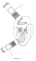
- Figure 1A shows, in its upper part, the application device (1) with the stent (3) mounted within in a stretched manner.
- the application device When the application device is positioned and the stent (3) is released in the myocardium valve of the patient, the stent expands so that the upper flap (8) of the stent (3) remains above the myocardium valve, while the lower flap (9) remains below the myocardium valve.
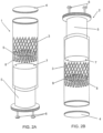
- Figures 2A and 2B show the assembly of the stent (3) within application devices (1) and (2), so that the stent (3) is stretched and compressed within the application device.
- the stent structure (3) is through the upper flap (8) which is attached to the plunger (5) by a screw (7).
- the application device must be introduced from the upper part of the myocardium.
- Figure 2B shows a configuration in which the stent (3) is positioned within the application device (2) in reverse form to the assembly of Figure 2A , which allows the same positioning of the stent (3) in the myocardium valve.
- the position in which the stent (3) is assembled within the application device (1 or 2) is determined by the introduction point of the application device in the myocardium.
- the application devices (1) or (2) may be used as storage means of the stent (3). Accordingly, there is the option of a cap (4), which seals the application device, allowing it to be filled with a preservative liquid.
- Figure 2C highlights the fixing feature of the stent (3) on the screws (7) of the application device (1 or 2) .
- Figure 3 features an exploded view of the stent (3) in an open position, an adapter (12) with a thread and a mechanical valve (11), which is fixed and guided by the movement device (13) which is attached to the valve (11) through fixing elements (14).
- the mechanical valve (11) may be replaced by a biological valve (10).
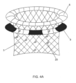
- Figures 4A , 4B and 4C show the stents (3) in an open position, respectively, without valves, with the biological valve (10) and with the mechanical valve (11).
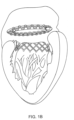
- Figure 4D shows the device, in a cross-sectional view, with the mechanical valve (11) installed in the stent body (3) with the upper flap (8) and the lower flap (9) in the position of application to the heart valve.
- the device of this invention comprises a stent assembly for heart valve and application device thereof.
- the stent comprises a tubular structure with one of its ends including an upper flap (8) and a lower flap (9).
- the stent requires a specific application device (1 or 2) to be used.
- the application device (1 or 2) features a plunger (5) with two screws (6) that pierce through it.
- the adjustments of the screws (6), in one of the ends, are located on the outer part of the application device (1 or 2) and the threaded end (7) is on the inner part of the application device.
- the stent (3) is attached and kept inside the application device, as seen in Figure 2C .
- the application device must have an anatomical shape, which facilitates intra-arterial movement until the inside of the cardiac muscle.
- a plasty ring may be featured or a previously inserted heart valve, which facilitates, in these situations, mechanical support of the stent.
- the stent must be placed within the application device (1 or 2). This is because the flaps (8 and 9) of the stent (3) have to be positioned in the heart valve, while the stent body must remain in the ventricular part of the valve.
- the stent (3) In case of an applying procedure from the upper part of the myocardium, the stent (3) must be assembled with the flaps near the plunger (5). In the procedure, from the lower part of the myocardium, the stent (3) must be assembled with the flaps (8 and 9) closer to the exit of the application device (2). With these two assemblies, the correct position of the stent (3) is ensured inside the heart valve. Furthermore, the stent (3) must have a valve in the inner part of its tubular structure. This valve must enable the blood flow to occur only on one direction: always from the atrium to the ventricle, avoiding backflow in the region.
- the valve is assembled in an adapter (12) which, in turn, is fixed to the stent body (3), preferably, between the flaps (8 and 9).
- the valve may be made of biological material (10) or mechanical (11).
- the stent (3) may be compressed within the application device (1 or 2) and kept inside with a preservative solution.
- mechanical valves (11) when mechanical valves (11) are used, the stent (3) must be stored without the mechanical valve (11), with only the upper flap (8) and lower flap (9) being compressed within the application device (1 or 2).
- the stent may be stored without the mechanical valve (11), with the mechanical valve-adapter (9) assembly fixed inside the stent (3) during the surgical procedure.
Description
- The invention is a stent with mechanical or biological heart valve as defined by claim 1 and a system as defined by
claim 7 including the stent of claim 1 and an application device. - This invention discloses a cardiac stent with a mechanism for positioning the mechanical or biological valve to be used during heart valve replacement or procedure, as well as a stent application device thereof. The stent has a tubular shape made of grated material with two flaps, with the heart valve fixed within. The application device comprises a syringe inside which the stent is placed, said syringe comprising a threaded cap that allows storage of the stent in a solution for conservation. Two screws pierce through the plunger of the syringe and fix the stent structure.
- The state of the art features a variety of devices for heart valve replacement, especially, by stents. Some of these stents feature an application device, specifically designed for the positioning procedure.
- The surgical approach of mitral valve pathologies demands the application of annuloplasty rings for fixing the base, which is a relatively time-consuming procedure, since anchoring of fixing wires is needed.
- Document
WO2009134701 (A2 ) features a positioning, opening and fixing system of a device for mitral valve replacement, which comprises a grated material that, when released from the application device, opens one of the ends which adapts to the shape of the mitral valve. The end that remains in the ventricle is fixed by tension wires anchored to the myocardium. Similar constructions are featured in theUS 2013/0172978 andWO 2013096541 . - In this application, as well as the other mentioned documents, a specific application device was developed for this stent.
- Differently, this invention comprises a cardiac stent for heart valve without using tension wires for fixing, in other words, this stent is fixed by flaps mounted in its own structure.
- The state of the art features a variety of distinct approaches to the treatment of dysfunctions associated to heart valves.
WO2012/063228 (A1 ) discloses a prosthesis for cardiovascular valve. One traditional method comprises the use of mechanical side-flow valves, such as the Starr-Edwards (initially disclosed in patentUS3099016 ). This device consists in a closure element - usually spherical - lodged in the path of the blood flow, diverting it. The initial project envisaged numerous disadvantages, such as structural fragility of the cage stems, low resistance of the sphere (causing injury to the septa) and the need of a permanent anticoagulant medicinal therapy for the patient. The position of the valves should also be highlighted as another impacting factor on patient health. - The evolution of replacement devices took place through development of forward flow mechanical valves, comprising pivotal structures that enabled a unidirectional blood flow. However, negative aspects remained, such as mechanical fatigue, use of anticoagulant medication and calcification of the heart valve. Partial solutions for the problem of the state of the art were described in documents
PI9700076-0 US6113631 . - An alternative proposal comprises the use of bioprosthesis or bioprosthetic valves, mainly built from biological tissue (bovine or pig pericardium), mimicking the leaflets that constitute human heart valves. Documents
PI9202905-1 US6358277 illustrate this concept. - On the other hand, the device revealed in document
PI0711664-0 WO2012106602 features an apparatus and a positioning method, incorporating some common elements toPI0711664-0 - The application
US2013079873 , in turn, describes a set comprising a prosthetic valve with a valve position and support, comprising fixing means for support to the mitral annulus, providing a closing mechanism in order to avoid slipping of the chains and mentioning the possibility of the fixing device being a screw. One of the limitations inherent to this device is the impossibility of timely adjustment of chain dimensions. In case adjustments are needed, the device must be taken off, adjusted and repositioned over the valve. Further, the exposure of fixing support elements facilitates contamination or even injury of cardiac muscles. - In view of the state of the art, this invention enables a new stent and application device concept, for heart valve replacement or exchange procedures, with higher reliability and lesser duration of the procedure and equipment costs.
-
-
Figure 1A shows that the application device may be introduced in the cardiac muscle in two ways. In both ways, the stent (3) is introduced by its application device (1 or 2), which may be positioned from the upper part of the heart, right atrium, left atrium or through the pulmonary artery (1), or, alternatively, from a cut on the lower part of the myocardium (2). -
Figures 2A and 2B feature assemblies of the stents within the application devices, respectively, according to the introduction procedure of the application device (1) from the upper part (1) or the application device (2) from the lower part (2) of the myocardium. Both assemblies are needed so that the stent (3) is positioned correctly within the heart valve. -
Figure 2C highlights a screw (7) that pierces through the plunger (5) of the application device (1) to connect to the stent structure (3), preferably, on the upper flap (8) of the stent. -
Figure 3 shows an exploded view of the assembly of the stent (3) in which an adapter (12) is fixed, where a mechanical valve (11) is screwed or, alternatively, a biological valve (10). -
Figures 4A ,4B and4C show, respectively, the open stent (3), without a heart valve, with a biological valve (10) or a mechanical valve (11).Figure 4D shows a cross-sectional view of the stent (3) with a mechanical valve (11). -
Figure 1A shows, in its upper part, the application device (1) with the stent (3) mounted within in a stretched manner. When the application device is positioned and the stent (3) is released in the myocardium valve of the patient, the stent expands so that the upper flap (8) of the stent (3) remains above the myocardium valve, while the lower flap (9) remains below the myocardium valve. - On the same
Figure 1A , a second procedure option is shown with the application device (2) from the lower part of the myocardium, so that the stent (3) is introduced by the application device. -
Figures 2A and 2B show the assembly of the stent (3) within application devices (1) and (2), so that the stent (3) is stretched and compressed within the application device. In assembly 2A, the stent structure (3) is through the upper flap (8) which is attached to the plunger (5) by a screw (7). In this embodiment, the application device must be introduced from the upper part of the myocardium.Figure 2B shows a configuration in which the stent (3) is positioned within the application device (2) in reverse form to the assembly ofFigure 2A , which allows the same positioning of the stent (3) in the myocardium valve. - In summary, the position in which the stent (3) is assembled within the application device (1 or 2) is determined by the introduction point of the application device in the myocardium.
- Additionally, the application devices (1) or (2) may be used as storage means of the stent (3). Accordingly, there is the option of a cap (4), which seals the application device, allowing it to be filled with a preservative liquid.
-
Figure 2C highlights the fixing feature of the stent (3) on the screws (7) of the application device (1 or 2) . -
Figure 3 features an exploded view of the stent (3) in an open position, an adapter (12) with a thread and a mechanical valve (11), which is fixed and guided by the movement device (13) which is attached to the valve (11) through fixing elements (14). Optionally, the mechanical valve (11) may be replaced by a biological valve (10). -
Figures 4A ,4B and4C show the stents (3) in an open position, respectively, without valves, with the biological valve (10) and with the mechanical valve (11). -
Figure 4D shows the device, in a cross-sectional view, with the mechanical valve (11) installed in the stent body (3) with the upper flap (8) and the lower flap (9) in the position of application to the heart valve. - The device of this invention comprises a stent assembly for heart valve and application device thereof. The stent comprises a tubular structure with one of its ends including an upper flap (8) and a lower flap (9). When the stent (3) is released from the application device (1 or 2), the tubular structure expands, and the flaps are opened, fixing the stent (3) to the heart valve.
- Due to its shape, the stent requires a specific application device (1 or 2) to be used. The application device (1 or 2) features a plunger (5) with two screws (6) that pierce through it. The adjustments of the screws (6), in one of the ends, are located on the outer part of the application device (1 or 2) and the threaded end (7) is on the inner part of the application device. In the threaded part (7), the stent (3) is attached and kept inside the application device, as seen in
Figure 2C . Preferably, the application device must have an anatomical shape, which facilitates intra-arterial movement until the inside of the cardiac muscle. - There is the option of keeping the application device assembled and sealed by a cap (4), allowing the stent (3) to be kept in a preservation solution, such as formaldehyde, for example.
- Whichever the procedure, a plasty ring may be featured or a previously inserted heart valve, which facilitates, in these situations, mechanical support of the stent. Depending on how the procedure is carried out, the stent must be placed within the application device (1 or 2). This is because the flaps (8 and 9) of the stent (3) have to be positioned in the heart valve, while the stent body must remain in the ventricular part of the valve.
- In case of an applying procedure from the upper part of the myocardium, the stent (3) must be assembled with the flaps near the plunger (5). In the procedure, from the lower part of the myocardium, the stent (3) must be assembled with the flaps (8 and 9) closer to the exit of the application device (2). With these two assemblies, the correct position of the stent (3) is ensured inside the heart valve. Furthermore, the stent (3) must have a valve in the inner part of its tubular structure. This valve must enable the blood flow to occur only on one direction: always from the atrium to the ventricle, avoiding backflow in the region.
- The valve is assembled in an adapter (12) which, in turn, is fixed to the stent body (3), preferably, between the flaps (8 and 9).
- The valve may be made of biological material (10) or mechanical (11). In case of a biological valve, the stent (3) may be compressed within the application device (1 or 2) and kept inside with a preservative solution. However, when mechanical valves (11) are used, the stent (3) must be stored without the mechanical valve (11), with only the upper flap (8) and lower flap (9) being compressed within the application device (1 or 2).
- Alternatively, the stent may be stored without the mechanical valve (11), with the mechanical valve-adapter (9) assembly fixed inside the stent (3) during the surgical procedure.
Claims (10)
- STENT WITH MECHANICAL OR BIOLOGICAL HEART VALVE FOR MINIMALLY INVASIVE VALVE REPLACEMENT PROCEDURE, comprising a stent body (3) of tubular shape and grated structure,
wherein one of the ends of the stent body (3) has an upper flap (8) and a second lower flap (9), the second lower flap (9) being near and parallel to the upper flap (8) and positioned between the upper flap (8) and an intermediate part of the stent body (3), with both flaps (8 and 9) and the stent body (3) made of wired material and coated with inert material, which allows in use physiological movement of the mitral annulus and fitting an adapter (12) within the stent body (3), which is used to support a mechanical (11) or biological (10) heart valve within the stent body (3) between both flaps (8 and 9), and wherein the stent is positioned in an annuloplasty ring, previously positioned in the natural heart valve where the stent body (3) is to be placed, with the ring placed between the upper flap (8) and lower flap (9) on the outer part of the stent body (3), wherein said mechanical (11) or biological (10) valve is screwed to said adapter (12). - STENT, according to claim 1 wherein
the mechanical (11) or biological (10) heart valve is a mechanical heart valve (11) with two floodgates that allow a unidirectional flow. - STENT, according to claim 1
wherein the mechanical (11) or biological (10) heart valve is a biological (10) heart valve produced from a bovine or pig pericardium. - STENT, according to any of the previous
claims, wherein the material of the stent body (3) has a radiographic opaque property, allowing it to be viewed through radiography. - STENT, according to any of the previous
claims when dependent on claim 1, wherein small hooks (20) are placed on the upper flap (8), lower flap (9) and the stent body (3) that grapple the patient's muscle, facilitating the positioning and fixing of the stent body (3) to the annuloplasty ring. - STENT, according to the previous claims,
wherein the upper flap (8) and lower flap (9) are made of metallic segments in its structure that aid the mechanical resistance of the flaps. - SYSTEM comprising a stent according to
the previous claims and an application device (1, 2), wherein the application device (1, 2)comprises a cylindrical body (15), in which there is a plunger (5) which is pierced through by two screws (6) that fix and attach the stent body (3), said stent being stretched and elongated inside said cylindrical body (15), wherein said stent is positioned in such a way that the end of said stent body (3), the end where the upper flap (8) and lower flap (9) are placed, is near said plunger (5), so that in use the first part to come out from said application device (1) during an applying procedure from the upper part of the myocardium is the part of the stent body (3) opposite said end. - SYSTEM, according to claim 7, wherein said stent body (3) is positioned within the cylindrical body (15) with the end of the stent body (3) where the flaps (8 and 9) are placed being close to the exit of the application device (2) and released first in use, in an opposite way with respect to the position of claim 7, during an applying procedure from the lower part of the myocardium.
- SYSTEM, according to claims 7 or 8,
wherein said application device (1, 2) has a thread, at the end where the stent comes out, that allows the placement of a cap (4) that seals the inner part of the cylindrical body (15) . - SYSTEM, according to any of claims 7-9
wherein said application device (1, 2) has a diameter large enough to keep said stent with mechanical valve (11) with only the flaps (8, 9) compressed within the application device.
Applications Claiming Priority (2)
| Application Number | Priority Date | Filing Date | Title |
|---|---|---|---|
| BR102014006114-2A BR102014006114B1 (en) | 2014-03-14 | 2014-03-14 | Mechanical or biological heart valve stent for minimally invasive valve replacement procedure and stent delivery device |
| PCT/BR2015/050024 WO2015135050A1 (en) | 2014-03-14 | 2015-02-27 | Stent with mechanical or biological heart valve for minimally invasive valve replacement procedure, and applicator |
Publications (4)
| Publication Number | Publication Date |
|---|---|
| EP3117802A1 EP3117802A1 (en) | 2017-01-18 |
| EP3117802A4 EP3117802A4 (en) | 2017-12-06 |
| EP3117802B1 true EP3117802B1 (en) | 2024-01-03 |
| EP3117802C0 EP3117802C0 (en) | 2024-01-03 |
Family
ID=54070718
Family Applications (1)
| Application Number | Title | Priority Date | Filing Date |
|---|---|---|---|
| EP15761481.9A Active EP3117802B1 (en) | 2014-03-14 | 2015-02-27 | Stent with mechanical or biological heart valve for minimally invasive valve replacement procedure, and applicator |
Country Status (7)
| Country | Link |
|---|---|
| US (1) | US20170056165A1 (en) |
| EP (1) | EP3117802B1 (en) |
| JP (1) | JP2017512607A (en) |
| CN (1) | CN106102659A (en) |
| BR (1) | BR102014006114B1 (en) |
| CA (1) | CA2939741A1 (en) |
| WO (1) | WO2015135050A1 (en) |
Families Citing this family (20)
| Publication number | Priority date | Publication date | Assignee | Title |
|---|---|---|---|---|
| CA2822381C (en) | 2010-12-23 | 2019-04-02 | Foundry Newco Xii, Inc. | System for mitral valve repair and replacement |
| WO2012177942A2 (en) | 2011-06-21 | 2012-12-27 | Hanson Gifford, Iii | Prosthetic heart valve devices and associated systems and methods |
| EP2750630B1 (en) | 2011-10-19 | 2021-06-30 | Twelve, Inc. | Device for heart valve replacement |
| US9655722B2 (en) | 2011-10-19 | 2017-05-23 | Twelve, Inc. | Prosthetic heart valve devices, prosthetic mitral valves and associated systems and methods |
| US9763780B2 (en) | 2011-10-19 | 2017-09-19 | Twelve, Inc. | Devices, systems and methods for heart valve replacement |
| JP6133309B2 (en) | 2011-10-19 | 2017-05-24 | トゥエルヴ, インコーポレイテッド | Prosthetic heart valve device |
| US11202704B2 (en) | 2011-10-19 | 2021-12-21 | Twelve, Inc. | Prosthetic heart valve devices, prosthetic mitral valves and associated systems and methods |
| US9039757B2 (en) | 2011-10-19 | 2015-05-26 | Twelve, Inc. | Prosthetic heart valve devices, prosthetic mitral valves and associated systems and methods |
| US9579198B2 (en) | 2012-03-01 | 2017-02-28 | Twelve, Inc. | Hydraulic delivery systems for prosthetic heart valve devices and associated methods |
| AU2014268631B2 (en) | 2013-05-20 | 2019-08-01 | Twelve, Inc. | Implantable heart valve devices, mitral valve repair devices and associated systems and methods |
| JP7111610B2 (en) | 2015-08-21 | 2022-08-02 | トゥエルヴ, インコーポレイテッド | Implantable Heart Valve Devices, Mitral Valve Repair Devices, and Related Systems and Methods |
| EP3448316B1 (en) | 2016-04-29 | 2023-03-29 | Medtronic Vascular Inc. | Prosthetic heart valve devices with tethered anchors |
| US10702378B2 (en) | 2017-04-18 | 2020-07-07 | Twelve, Inc. | Prosthetic heart valve device and associated systems and methods |
| US10575950B2 (en) | 2017-04-18 | 2020-03-03 | Twelve, Inc. | Hydraulic systems for delivering prosthetic heart valve devices and associated methods |
| US10433961B2 (en) | 2017-04-18 | 2019-10-08 | Twelve, Inc. | Delivery systems with tethers for prosthetic heart valve devices and associated methods |
| US10792151B2 (en) | 2017-05-11 | 2020-10-06 | Twelve, Inc. | Delivery systems for delivering prosthetic heart valve devices and associated methods |
| US10646338B2 (en) | 2017-06-02 | 2020-05-12 | Twelve, Inc. | Delivery systems with telescoping capsules for deploying prosthetic heart valve devices and associated methods |
| US10709591B2 (en) | 2017-06-06 | 2020-07-14 | Twelve, Inc. | Crimping device and method for loading stents and prosthetic heart valves |
| US10729541B2 (en) | 2017-07-06 | 2020-08-04 | Twelve, Inc. | Prosthetic heart valve devices and associated systems and methods |
| US10786352B2 (en) | 2017-07-06 | 2020-09-29 | Twelve, Inc. | Prosthetic heart valve devices and associated systems and methods |
Family Cites Families (61)
| Publication number | Priority date | Publication date | Assignee | Title |
|---|---|---|---|---|
| US4680031A (en) * | 1982-11-29 | 1987-07-14 | Tascon Medical Technology Corporation | Heart valve prosthesis |
| US5035709A (en) * | 1990-03-29 | 1991-07-30 | Baxter International Inc. | Mechanical heart valve with compliant sewing ring |
| US5258023A (en) * | 1992-02-12 | 1993-11-02 | Reger Medical Development, Inc. | Prosthetic heart valve |
| US5716417A (en) * | 1995-06-07 | 1998-02-10 | St. Jude Medical, Inc. | Integral supporting structure for bioprosthetic heart valve |
| US5855601A (en) * | 1996-06-21 | 1999-01-05 | The Trustees Of Columbia University In The City Of New York | Artificial heart valve and method and device for implanting the same |
| US6530952B2 (en) * | 1997-12-29 | 2003-03-11 | The Cleveland Clinic Foundation | Bioprosthetic cardiovascular valve system |
| US6425916B1 (en) * | 1999-02-10 | 2002-07-30 | Michi E. Garrison | Methods and devices for implanting cardiac valves |
| JP3944555B2 (en) * | 1999-10-06 | 2007-07-11 | キヤノンスター株式会社 | Intraocular lens insertion system |
| US6458153B1 (en) * | 1999-12-31 | 2002-10-01 | Abps Venture One, Ltd. | Endoluminal cardiac and venous valve prostheses and methods of manufacture and delivery thereof |
| WO2002039908A2 (en) * | 2000-11-16 | 2002-05-23 | Hill J Donald | Automatic suture fixation apparatus and method |
| US7097659B2 (en) * | 2001-09-07 | 2006-08-29 | Medtronic, Inc. | Fixation band for affixing a prosthetic heart valve to tissue |
| DE60309281T3 (en) * | 2003-02-10 | 2013-12-12 | Heraeus Precious Metals Gmbh & Co. Kg | Improved metal alloy for medical devices and implants |
| WO2004103223A1 (en) * | 2003-05-20 | 2004-12-02 | The Cleveland Clinic Foundation | Apparatus and methods for repair of a cardiac valve |
| US7381219B2 (en) * | 2003-12-23 | 2008-06-03 | Sadra Medical, Inc. | Low profile heart valve and delivery system |
| WO2005065592A1 (en) * | 2003-12-30 | 2005-07-21 | Bausch & Lomb Incorporated | Improved iol inserter plunger |
| US7311730B2 (en) * | 2004-02-13 | 2007-12-25 | Shlomo Gabbay | Support apparatus and heart valve prosthesis for sutureless implantation |
| NL1025830C2 (en) * | 2004-03-26 | 2005-02-22 | Eric Berreklouw | Prosthesis e.g. heart valve secured in place by ring with shape memory material anchor, includes anchor temperature control system |
| US20060052867A1 (en) * | 2004-09-07 | 2006-03-09 | Medtronic, Inc | Replacement prosthetic heart valve, system and method of implant |
| WO2006070628A1 (en) * | 2004-12-27 | 2006-07-06 | Hoya Corporation | Intraocular lens implanting device |
| JP4836046B2 (en) * | 2005-02-24 | 2011-12-14 | Hoya株式会社 | Intraocular lens insertion device |
| US7297149B2 (en) * | 2005-04-14 | 2007-11-20 | Ethicon Endo-Surgery, Inc. | Surgical clip applier methods |
| EP1883375B1 (en) * | 2005-05-24 | 2016-12-07 | Edwards Lifesciences Corporation | Rapid deployment prosthetic heart valve |
| JP4877643B2 (en) * | 2005-12-08 | 2012-02-15 | Hoya株式会社 | Intraocular lens insertion device |
| US20070213813A1 (en) * | 2005-12-22 | 2007-09-13 | Symetis Sa | Stent-valves for valve replacement and associated methods and systems for surgery |
| US7935144B2 (en) * | 2006-10-19 | 2011-05-03 | Direct Flow Medical, Inc. | Profile reduction of valve implant |
| WO2008089365A2 (en) * | 2007-01-19 | 2008-07-24 | The Cleveland Clinic Foundation | Method for implanting a cardiovascular valve |
| CN101677853B (en) * | 2007-05-30 | 2012-04-18 | Hoya株式会社 | Intraocular lens inserting tool |
| JP5236638B2 (en) * | 2007-05-30 | 2013-07-17 | Hoya株式会社 | Intraocular lens insertion device |
| JP5086713B2 (en) * | 2007-07-11 | 2012-11-28 | Hoya株式会社 | Intraocular lens insertion device |
| CN101354507B (en) * | 2007-07-26 | 2010-10-06 | 北京京东方光电科技有限公司 | Thin-film transistor LCD device array substrate structure and manufacturing method thereof |
| US8747458B2 (en) * | 2007-08-20 | 2014-06-10 | Medtronic Ventor Technologies Ltd. | Stent loading tool and method for use thereof |
| US9532868B2 (en) * | 2007-09-28 | 2017-01-03 | St. Jude Medical, Inc. | Collapsible-expandable prosthetic heart valves with structures for clamping native tissue |
| US8317858B2 (en) * | 2008-02-26 | 2012-11-27 | Jenavalve Technology, Inc. | Stent for the positioning and anchoring of a valvular prosthesis in an implantation site in the heart of a patient |
| US9241792B2 (en) * | 2008-02-29 | 2016-01-26 | Edwards Lifesciences Corporation | Two-step heart valve implantation |
| US8313525B2 (en) * | 2008-03-18 | 2012-11-20 | Medtronic Ventor Technologies, Ltd. | Valve suturing and implantation procedures |
| US20090276040A1 (en) * | 2008-05-01 | 2009-11-05 | Edwards Lifesciences Corporation | Device and method for replacing mitral valve |
| WO2010011699A2 (en) * | 2008-07-21 | 2010-01-28 | White Jennifer K | Repositionable endoluminal support structure and its applications |
| US8308798B2 (en) * | 2008-12-19 | 2012-11-13 | Edwards Lifesciences Corporation | Quick-connect prosthetic heart valve and methods |
| SG172876A1 (en) * | 2009-01-07 | 2011-08-29 | Hoya Corp | Intraocular lens insertion device |
| TWI524238B (en) * | 2009-03-31 | 2016-03-01 | 萬國商業機器公司 | Multi-touch optical touch panel |
| CA2961053C (en) * | 2009-04-15 | 2019-04-30 | Edwards Lifesciences Cardiaq Llc | Vascular implant and delivery system |
| NZ624106A (en) * | 2009-04-29 | 2015-12-24 | Cleveland Clinic Foundation | Apparatus and method for replacing a diseased cardiac valve |
| US8348998B2 (en) * | 2009-06-26 | 2013-01-08 | Edwards Lifesciences Corporation | Unitary quick connect prosthetic heart valve and deployment system and methods |
| DE102009037739A1 (en) * | 2009-06-29 | 2010-12-30 | Be Innovative Gmbh | Percutaneously implantable valve stent, device for its application and method for producing the valve stent |
| US8449599B2 (en) * | 2009-12-04 | 2013-05-28 | Edwards Lifesciences Corporation | Prosthetic valve for replacing mitral valve |
| US8869982B2 (en) * | 2009-12-18 | 2014-10-28 | Edwards Lifesciences Corporation | Prosthetic heart valve packaging and deployment system |
| JP5511530B2 (en) * | 2010-06-10 | 2014-06-04 | Hoya株式会社 | Intraocular lens insertion device |
| US8657872B2 (en) * | 2010-07-19 | 2014-02-25 | Jacques Seguin | Cardiac valve repair system and methods of use |
| US9132009B2 (en) * | 2010-07-21 | 2015-09-15 | Mitraltech Ltd. | Guide wires with commissural anchors to advance a prosthetic valve |
| AU2011292461B2 (en) * | 2010-08-17 | 2014-05-01 | St. Jude Medical, Cardiology Division, Inc. | A device for collapsing and loading a heart valve into a minimally invasive delivery system |
| IT1402571B1 (en) * | 2010-11-12 | 2013-09-13 | Ht Consultant Di Giovanni Righini | PROSTHETIC SYSTEM FOR CARDIO-VASCULAR VALVE WITH SEPARATE ANCHORAGE STRUCTURE |
| EP2484309B1 (en) * | 2011-02-02 | 2019-04-10 | Shlomo Gabbay | Heart valve prosthesis |
| US8840664B2 (en) * | 2011-06-15 | 2014-09-23 | Edwards Lifesciences Corporation | Heart valve prosthesis anchoring device and methods |
| EP2723272A4 (en) * | 2011-06-24 | 2015-01-28 | Inceptus Medical LLC | Percutaneously implantable artificial heart valve system and associated methods and devices |
| US9662206B2 (en) * | 2011-09-12 | 2017-05-30 | Highlife Sas | Transcatheter valve prosthesis |
| CN202313807U (en) * | 2011-10-14 | 2012-07-11 | 邹煜 | Artificial-valve bicuspid-valve membrane-covered stent with asymmetrical atrioventricular fixing structure |
| EP2601897A1 (en) * | 2011-12-07 | 2013-06-12 | JenaValve Technology Inc. | Access device for cardiac stent delivery and method for fixing the same |
| LT2852354T (en) * | 2012-05-20 | 2020-09-25 | Tel Hashomer Medical Research Infrastructure And Services Ltd. | Prosthetic mitral valve |
| US20140031923A1 (en) * | 2012-07-25 | 2014-01-30 | Medtronic Vascular Galway Limited | Trans-Aortic Surgical Syringe-Type Device for Deployment of a Prosthetic Valve |
| WO2014089250A1 (en) * | 2012-12-05 | 2014-06-12 | Hoya Corporation | Ocular implant insertion apparatus and methods |
| US9730791B2 (en) * | 2013-03-14 | 2017-08-15 | Edwards Lifesciences Cardiaq Llc | Prosthesis for atraumatically grasping intralumenal tissue and methods of delivery |
-
2014
- 2014-03-14 BR BR102014006114-2A patent/BR102014006114B1/en active IP Right Grant
-
2015
- 2015-02-27 JP JP2016574307A patent/JP2017512607A/en active Pending
- 2015-02-27 US US15/118,841 patent/US20170056165A1/en not_active Abandoned
- 2015-02-27 CA CA2939741A patent/CA2939741A1/en not_active Abandoned
- 2015-02-27 CN CN201580013457.9A patent/CN106102659A/en active Pending
- 2015-02-27 WO PCT/BR2015/050024 patent/WO2015135050A1/en active Application Filing
- 2015-02-27 EP EP15761481.9A patent/EP3117802B1/en active Active
Also Published As
| Publication number | Publication date |
|---|---|
| BR102014006114B1 (en) | 2022-05-10 |
| CA2939741A1 (en) | 2015-09-17 |
| EP3117802A4 (en) | 2017-12-06 |
| US20170056165A1 (en) | 2017-03-02 |
| WO2015135050A1 (en) | 2015-09-17 |
| CN106102659A (en) | 2016-11-09 |
| EP3117802A1 (en) | 2017-01-18 |
| EP3117802C0 (en) | 2024-01-03 |
| BR102014006114A2 (en) | 2016-01-26 |
| JP2017512607A (en) | 2017-05-25 |
Similar Documents
| Publication | Publication Date | Title |
|---|---|---|
| EP3117802B1 (en) | Stent with mechanical or biological heart valve for minimally invasive valve replacement procedure, and applicator | |
| US11076955B2 (en) | Implantable prosthetic heart valve | |
| US20220023039A1 (en) | Two-part bi-leaflet heart valve prostheses | |
| CN109414321B (en) | Device for treating valve regurgitation | |
| CN108495600B (en) | Assembly for replacing an atrioventricular tricuspid valve | |
| JP7036556B2 (en) | Stent with valve for replacement of heart mitral and tricuspid valves | |
| US8349001B2 (en) | Pharmacological delivery implement for use with cardiac repair devices | |
| US10245142B2 (en) | Multiple orifice implantable heart valve and methods of implantation | |
| CA2556077C (en) | Transcatheter delivery of a replacement heart valve | |
| EP2949292B1 (en) | Replacement valve | |
| JP2018047242A5 (en) | ||
| US20080103586A1 (en) | Implant for placing in a blood circulation conduit | |
| US20070233237A1 (en) | Valved Conduit Designed for Subsequent Catheter Delivered Valve Therapy | |
| EP3668455B1 (en) | Heart valve frame design with non-uniform struts | |
| US20090222082A1 (en) | Transcatheter Heart Valve Prostheses | |
| US20180243087A1 (en) | Systems and methods for treating a regurgitant heart valve | |
| EP2578166A3 (en) | Devices for transcatheter prosthetic heart valve implantation and access closure | |
| CN104055604A (en) | Heart valve implantation device provided with anchoring device | |
| CN104248457B (en) | A kind of artificial cords device, connect element and external member | |
| WO2019062366A1 (en) | Heart valve prosthesis | |
| Lange et al. | The HighLife transcatheter mitral valve implantation system | |
| EP3960129A1 (en) | Prosthetic heart valve | |
| CN215349758U (en) | Implant structure and have its conveyer subassembly | |
| CN116725737A (en) | artificial heart valve |
Legal Events
| Date | Code | Title | Description |
|---|---|---|---|
| PUAI | Public reference made under article 153(3) epc to a published international application that has entered the european phase |
Free format text: ORIGINAL CODE: 0009012 |
|
| STAA | Information on the status of an ep patent application or granted ep patent |
Free format text: STATUS: REQUEST FOR EXAMINATION WAS MADE |
|
| 17P | Request for examination filed |
Effective date: 20160916 |
|
| AK | Designated contracting states |
Kind code of ref document: A1 Designated state(s): AL AT BE BG CH CY CZ DE DK EE ES FI FR GB GR HR HU IE IS IT LI LT LU LV MC MK MT NL NO PL PT RO RS SE SI SK SM TR |
|
| AX | Request for extension of the european patent |
Extension state: BA ME |
|
| DAX | Request for extension of the european patent (deleted) | ||
| A4 | Supplementary search report drawn up and despatched |
Effective date: 20171108 |
|
| RIC1 | Information provided on ipc code assigned before grant |
Ipc: A61F 2/95 20130101ALI20171102BHEP Ipc: A61F 2/24 20060101ALI20171102BHEP Ipc: A61F 2/82 20130101AFI20171102BHEP |
|
| STAA | Information on the status of an ep patent application or granted ep patent |
Free format text: STATUS: EXAMINATION IS IN PROGRESS |
|
| STAA | Information on the status of an ep patent application or granted ep patent |
Free format text: STATUS: EXAMINATION IS IN PROGRESS |
|
| 17Q | First examination report despatched |
Effective date: 20201124 |
|
| STAA | Information on the status of an ep patent application or granted ep patent |
Free format text: STATUS: EXAMINATION IS IN PROGRESS |
|
| GRAP | Despatch of communication of intention to grant a patent |
Free format text: ORIGINAL CODE: EPIDOSNIGR1 |
|
| STAA | Information on the status of an ep patent application or granted ep patent |
Free format text: STATUS: GRANT OF PATENT IS INTENDED |
|
| INTG | Intention to grant announced |
Effective date: 20230724 |
|
| GRAS | Grant fee paid |
Free format text: ORIGINAL CODE: EPIDOSNIGR3 |
|
| GRAA | (expected) grant |
Free format text: ORIGINAL CODE: 0009210 |
|
| STAA | Information on the status of an ep patent application or granted ep patent |
Free format text: STATUS: THE PATENT HAS BEEN GRANTED |
|
| AK | Designated contracting states |
Kind code of ref document: B1 Designated state(s): AL AT BE BG CH CY CZ DE DK EE ES FI FR GB GR HR HU IE IS IT LI LT LU LV MC MK MT NL NO PL PT RO RS SE SI SK SM TR |
|
| REG | Reference to a national code |
Ref country code: GB Ref legal event code: FG4D |
|
| REG | Reference to a national code |
Ref country code: DE Ref legal event code: R096 Ref document number: 602015087139 Country of ref document: DE |
|
| REG | Reference to a national code |
Ref country code: CH Ref legal event code: EP |
|
| REG | Reference to a national code |
Ref country code: IE Ref legal event code: FG4D |
|
| U01 | Request for unitary effect filed |
Effective date: 20240202 |
|
| U07 | Unitary effect registered |
Designated state(s): AT BE BG DE DK EE FI FR IT LT LU LV MT NL PT SE SI Effective date: 20240212 |
|
| U20 | Renewal fee paid [unitary effect] |
Year of fee payment: 10 Effective date: 20240226 |