EP3116403B1 - Image registration and guidance using concurrent x-plane imaging - Google Patents
Image registration and guidance using concurrent x-plane imaging Download PDFInfo
- Publication number
- EP3116403B1 EP3116403B1 EP15711828.2A EP15711828A EP3116403B1 EP 3116403 B1 EP3116403 B1 EP 3116403B1 EP 15711828 A EP15711828 A EP 15711828A EP 3116403 B1 EP3116403 B1 EP 3116403B1
- Authority
- EP
- European Patent Office
- Prior art keywords
- images
- imaging
- image
- alignment
- planes
- Prior art date
- Legal status (The legal status is an assumption and is not a legal conclusion. Google has not performed a legal analysis and makes no representation as to the accuracy of the status listed.)
- Active
Links
- 238000003384 imaging method Methods 0.000 title claims description 127
- 238000002591 computed tomography Methods 0.000 claims description 76
- 238000002604 ultrasonography Methods 0.000 claims description 70
- 230000007246 mechanism Effects 0.000 claims description 49
- 239000000523 sample Substances 0.000 claims description 47
- 238000000034 method Methods 0.000 claims description 39
- 230000003068 static effect Effects 0.000 claims description 15
- 238000012545 processing Methods 0.000 claims description 14
- 230000000007 visual effect Effects 0.000 claims description 10
- 238000002600 positron emission tomography Methods 0.000 claims description 5
- 238000002603 single-photon emission computed tomography Methods 0.000 claims description 5
- 230000003902 lesion Effects 0.000 description 20
- 230000004927 fusion Effects 0.000 description 12
- 238000010586 diagram Methods 0.000 description 10
- 238000012800 visualization Methods 0.000 description 9
- 230000006870 function Effects 0.000 description 7
- 230000008569 process Effects 0.000 description 5
- 230000008901 benefit Effects 0.000 description 4
- 210000000056 organ Anatomy 0.000 description 4
- 206010028980 Neoplasm Diseases 0.000 description 3
- 230000003287 optical effect Effects 0.000 description 3
- 210000003484 anatomy Anatomy 0.000 description 2
- 238000012512 characterization method Methods 0.000 description 2
- 238000012937 correction Methods 0.000 description 2
- 230000000694 effects Effects 0.000 description 2
- 239000004065 semiconductor Substances 0.000 description 2
- 230000008685 targeting Effects 0.000 description 2
- 210000001015 abdomen Anatomy 0.000 description 1
- 238000013459 approach Methods 0.000 description 1
- 238000001574 biopsy Methods 0.000 description 1
- 210000004204 blood vessel Anatomy 0.000 description 1
- 238000004891 communication Methods 0.000 description 1
- 238000004590 computer program Methods 0.000 description 1
- 230000001419 dependent effect Effects 0.000 description 1
- 238000002059 diagnostic imaging Methods 0.000 description 1
- 229940079593 drug Drugs 0.000 description 1
- 239000003814 drug Substances 0.000 description 1
- 238000005516 engineering process Methods 0.000 description 1
- 210000001035 gastrointestinal tract Anatomy 0.000 description 1
- 230000003993 interaction Effects 0.000 description 1
- 238000013152 interventional procedure Methods 0.000 description 1
- 238000010859 live-cell imaging Methods 0.000 description 1
- 238000007726 management method Methods 0.000 description 1
- 239000011159 matrix material Substances 0.000 description 1
- 230000000116 mitigating effect Effects 0.000 description 1
- 238000012986 modification Methods 0.000 description 1
- 230000004048 modification Effects 0.000 description 1
- 230000002093 peripheral effect Effects 0.000 description 1
- 230000000644 propagated effect Effects 0.000 description 1
- 238000009877 rendering Methods 0.000 description 1
- 239000007787 solid Substances 0.000 description 1
Images


Classifications
-
- A—HUMAN NECESSITIES
- A61—MEDICAL OR VETERINARY SCIENCE; HYGIENE
- A61B—DIAGNOSIS; SURGERY; IDENTIFICATION
- A61B8/00—Diagnosis using ultrasonic, sonic or infrasonic waves
- A61B8/52—Devices using data or image processing specially adapted for diagnosis using ultrasonic, sonic or infrasonic waves
- A61B8/5215—Devices using data or image processing specially adapted for diagnosis using ultrasonic, sonic or infrasonic waves involving processing of medical diagnostic data
- A61B8/5238—Devices using data or image processing specially adapted for diagnosis using ultrasonic, sonic or infrasonic waves involving processing of medical diagnostic data for combining image data of patient, e.g. merging several images from different acquisition modes into one image
- A61B8/5261—Devices using data or image processing specially adapted for diagnosis using ultrasonic, sonic or infrasonic waves involving processing of medical diagnostic data for combining image data of patient, e.g. merging several images from different acquisition modes into one image combining images from different diagnostic modalities, e.g. ultrasound and X-ray
-
- A—HUMAN NECESSITIES
- A61—MEDICAL OR VETERINARY SCIENCE; HYGIENE
- A61B—DIAGNOSIS; SURGERY; IDENTIFICATION
- A61B8/00—Diagnosis using ultrasonic, sonic or infrasonic waves
- A61B8/52—Devices using data or image processing specially adapted for diagnosis using ultrasonic, sonic or infrasonic waves
- A61B8/5215—Devices using data or image processing specially adapted for diagnosis using ultrasonic, sonic or infrasonic waves involving processing of medical diagnostic data
- A61B8/5238—Devices using data or image processing specially adapted for diagnosis using ultrasonic, sonic or infrasonic waves involving processing of medical diagnostic data for combining image data of patient, e.g. merging several images from different acquisition modes into one image
- A61B8/5246—Devices using data or image processing specially adapted for diagnosis using ultrasonic, sonic or infrasonic waves involving processing of medical diagnostic data for combining image data of patient, e.g. merging several images from different acquisition modes into one image combining images from the same or different imaging techniques, e.g. color Doppler and B-mode
-
- A—HUMAN NECESSITIES
- A61—MEDICAL OR VETERINARY SCIENCE; HYGIENE
- A61B—DIAGNOSIS; SURGERY; IDENTIFICATION
- A61B5/00—Measuring for diagnostic purposes; Identification of persons
- A61B5/05—Detecting, measuring or recording for diagnosis by means of electric currents or magnetic fields; Measuring using microwaves or radio waves
- A61B5/055—Detecting, measuring or recording for diagnosis by means of electric currents or magnetic fields; Measuring using microwaves or radio waves involving electronic [EMR] or nuclear [NMR] magnetic resonance, e.g. magnetic resonance imaging
-
- A—HUMAN NECESSITIES
- A61—MEDICAL OR VETERINARY SCIENCE; HYGIENE
- A61B—DIAGNOSIS; SURGERY; IDENTIFICATION
- A61B6/00—Apparatus or devices for radiation diagnosis; Apparatus or devices for radiation diagnosis combined with radiation therapy equipment
- A61B6/02—Arrangements for diagnosis sequentially in different planes; Stereoscopic radiation diagnosis
- A61B6/025—Tomosynthesis
-
- A—HUMAN NECESSITIES
- A61—MEDICAL OR VETERINARY SCIENCE; HYGIENE
- A61B—DIAGNOSIS; SURGERY; IDENTIFICATION
- A61B6/00—Apparatus or devices for radiation diagnosis; Apparatus or devices for radiation diagnosis combined with radiation therapy equipment
- A61B6/02—Arrangements for diagnosis sequentially in different planes; Stereoscopic radiation diagnosis
- A61B6/03—Computed tomography [CT]
- A61B6/032—Transmission computed tomography [CT]
-
- A—HUMAN NECESSITIES
- A61—MEDICAL OR VETERINARY SCIENCE; HYGIENE
- A61B—DIAGNOSIS; SURGERY; IDENTIFICATION
- A61B6/00—Apparatus or devices for radiation diagnosis; Apparatus or devices for radiation diagnosis combined with radiation therapy equipment
- A61B6/02—Arrangements for diagnosis sequentially in different planes; Stereoscopic radiation diagnosis
- A61B6/03—Computed tomography [CT]
- A61B6/037—Emission tomography
-
- A—HUMAN NECESSITIES
- A61—MEDICAL OR VETERINARY SCIENCE; HYGIENE
- A61B—DIAGNOSIS; SURGERY; IDENTIFICATION
- A61B8/00—Diagnosis using ultrasonic, sonic or infrasonic waves
- A61B8/08—Detecting organic movements or changes, e.g. tumours, cysts, swellings
- A61B8/0833—Detecting organic movements or changes, e.g. tumours, cysts, swellings involving detecting or locating foreign bodies or organic structures
- A61B8/0841—Detecting organic movements or changes, e.g. tumours, cysts, swellings involving detecting or locating foreign bodies or organic structures for locating instruments
-
- A—HUMAN NECESSITIES
- A61—MEDICAL OR VETERINARY SCIENCE; HYGIENE
- A61B—DIAGNOSIS; SURGERY; IDENTIFICATION
- A61B8/00—Diagnosis using ultrasonic, sonic or infrasonic waves
- A61B8/42—Details of probe positioning or probe attachment to the patient
- A61B8/4245—Details of probe positioning or probe attachment to the patient involving determining the position of the probe, e.g. with respect to an external reference frame or to the patient
-
- A—HUMAN NECESSITIES
- A61—MEDICAL OR VETERINARY SCIENCE; HYGIENE
- A61B—DIAGNOSIS; SURGERY; IDENTIFICATION
- A61B8/00—Diagnosis using ultrasonic, sonic or infrasonic waves
- A61B8/46—Ultrasonic, sonic or infrasonic diagnostic devices with special arrangements for interfacing with the operator or the patient
- A61B8/461—Displaying means of special interest
- A61B8/463—Displaying means of special interest characterised by displaying multiple images or images and diagnostic data on one display
-
- A—HUMAN NECESSITIES
- A61—MEDICAL OR VETERINARY SCIENCE; HYGIENE
- A61B—DIAGNOSIS; SURGERY; IDENTIFICATION
- A61B8/00—Diagnosis using ultrasonic, sonic or infrasonic waves
- A61B8/46—Ultrasonic, sonic or infrasonic diagnostic devices with special arrangements for interfacing with the operator or the patient
- A61B8/467—Ultrasonic, sonic or infrasonic diagnostic devices with special arrangements for interfacing with the operator or the patient characterised by special input means
-
- A—HUMAN NECESSITIES
- A61—MEDICAL OR VETERINARY SCIENCE; HYGIENE
- A61B—DIAGNOSIS; SURGERY; IDENTIFICATION
- A61B8/00—Diagnosis using ultrasonic, sonic or infrasonic waves
- A61B8/48—Diagnostic techniques
- A61B8/483—Diagnostic techniques involving the acquisition of a 3D volume of data
-
- A—HUMAN NECESSITIES
- A61—MEDICAL OR VETERINARY SCIENCE; HYGIENE
- A61B—DIAGNOSIS; SURGERY; IDENTIFICATION
- A61B8/00—Diagnosis using ultrasonic, sonic or infrasonic waves
- A61B8/54—Control of the diagnostic device
-
- A—HUMAN NECESSITIES
- A61—MEDICAL OR VETERINARY SCIENCE; HYGIENE
- A61B—DIAGNOSIS; SURGERY; IDENTIFICATION
- A61B6/00—Apparatus or devices for radiation diagnosis; Apparatus or devices for radiation diagnosis combined with radiation therapy equipment
- A61B6/52—Devices using data or image processing specially adapted for radiation diagnosis
- A61B6/5211—Devices using data or image processing specially adapted for radiation diagnosis involving processing of medical diagnostic data
- A61B6/5229—Devices using data or image processing specially adapted for radiation diagnosis involving processing of medical diagnostic data combining image data of a patient, e.g. combining a functional image with an anatomical image
- A61B6/5235—Devices using data or image processing specially adapted for radiation diagnosis involving processing of medical diagnostic data combining image data of a patient, e.g. combining a functional image with an anatomical image combining images from the same or different ionising radiation imaging techniques, e.g. PET and CT
Definitions
- This disclosure relates to medical instruments and more particularly to imaging systems and methods, which employ multiple planes for image registration and guidance for medical devices.
- Image fusion relates to the process of reformatting and displaying an image slice through a volume data set (e.g., computed tomography (CT) or magnetic resonance (MR)) that corresponds with a scan plane of a live ultrasound image.
- CT computed tomography
- MR magnetic resonance
- the reformatted CT can be overlaid either on the live ultrasound image or shown in a side-by-side format.
- CT provides better lesion visualization for some tumors as compared with ultrasound.
- Ultrasound provides a live image whereas the CT represents a static snapshot of a patient's anatomy.
- One advantage of image fusion is that image fusion provides the advantages of both modalities. For example, the good lesion visualization from a CT is provided with the live information and feedback from an ultrasound when the two modalities are fused. Image fusion can be employed to target small lesions that are poorly visualized in live ultrasound.
- the ultrasound images need to be registered to the CT images. Registration is the correlation of spatial locations in the CT images to the same spatial locations in the ultrasound images.
- Conventional probes generate a single scan plane along an azimuthal plane.
- Conventional registration with conventional transducers may employ a manual plane match, which is fast but prone to errors due to probe angle in the sagittal (non-imaged) plane.
- conventional probes can only show one plane through a targeted lesion, and frequently, even though the scan plane appears to be going through a center of a targeted lesion, partial volume effects can result in the scan plane being off-center. Consequences may include imprecise needle placement for biopsies and procedures or other errors.
- Document US 2006/020204 A1 describes a system and a method for the imaging management of a 3D space where various substantially real-time scan images have been acquired.
- a user can visualize images of a portion of a body or object obtained from a substantially real-time scanner not just as 2D images, but as positionally- and orientationally-located slices within a particular 3D space.
- the user can also convert such slices into volumes whenever needed, and can process the images or volumes using known techniques.
- a system for image alignment includes an alignment mechanism configured to permit user alignment of images.
- a first imaging modality is configured to concurrently provide images in two or more imaging planes.
- An image processing module is configured to display first images collected with the first imaging modality and second images collected with a second imaging modality to permit user alignment using the alignment mechanism between the first images and the second images in multiple planes.
- a registration module is stored in memory and configured to register the first images with corresponding second images in the multiple planes when alignment in the multiple planes has been achieved.
- a system for procedure guidance includes multiple planes of fused images, and the multiple plane displays are used for procedure guidance.
- a system for image alignment includes an alignment mechanism configured to permit user alignment of images.
- a first imaging modality is configured to concurrently provide images in two imaging planes using an imaging mechanism associated with the alignment mechanism.
- An image processing module is configured to display first images collected with the first imaging modality and second images collected with a second imaging modality to permit user alignment using the alignment mechanism between the first images and the second images in multiple planes.
- a registration module is stored in memory and configured to register the first images with corresponding second images in the multiple planes when alignment in the multiple planes has been achieved.
- Another system for image alignment includes first images taken in real-time by a first imaging modality and second images taken using a second imaging modality.
- a probe associated with the first imaging modality is configured to concurrently provide images in at least two imaging planes corresponding with imaging planes of the second images.
- An image processing module is configured to display the first images and the second images on each of the at least two planes to permit user alignment between the first images and the second images in multiple planes by manipulation of the probe.
- a registration module is stored in memory and configured to register the first images with corresponding second images in the at least two planes when alignment in the multiple planes has been achieved.
- a method for image alignment includes positioning an alignment mechanism associated with a first imaging modality to concurrently provide images in at least two imaging planes for a subject; processing first images collected with the first imaging modality and second images collected with a second imaging modality to permit user alignment between the first images and the second images in multiple planes; visually aligning corresponding first and second images in the multiple planes using the alignment mechanism; and locking in the alignment of the first images with corresponding second images in the multiple planes when visual alignment in the multiple planes has been achieved.
- Another method for instrument guidance includes acquiring real-time images with a first modality in at least two imaging planes; fusing the real-time images with second images collected with a second imaging modality that correspond to the real-time images in the at least two imaging planes to generate fused images; and guiding an instrument by concurrently visualizing the fused images in the at least two imaging planes to position the instrument during a procedure.
- an imaging and alignment mechanism or feature e.g., an electronic three-dimensional (3D) probe
- an electronic three-dimensional (3D) probe may be employed to generate live X-planes for alignment and simultaneous image fusion, registration and display in multiple planes.
- the electronic 3D probe is capable of generating orthogonal X-planes, multi-planar renderings (MPRs) or even any arbitrary slice through a volume.
- real-time images may be registered with static images (e.g., computed tomography (CT), magnetic resonance (MR), positron emission tomography (PET), single photon emission computed tomography (SPECT), cone-beam CT, tomosynthesis, prior ultrasound volume, etc.).
- static images e.g., computed tomography (CT), magnetic resonance (MR), positron emission tomography (PET), single photon emission computed tomography (SPECT), cone-beam CT, tomosynthesis, prior ultrasound volume, etc.
- CT computed tomography
- MR magnetic resonance
- PET positron emission tomography
- SPECT single photon emission computed tomography
- cone-beam CT tomosynthesis
- prior ultrasound volume prior ultrasound volume, etc.
- the present principles may be employed in image alignment, image fusion/registration and instrument guidance using the multi-plane visualization.
- Concurrent live imaging with orthogonal planes with an electronic 3D probe provides visualization of at least two planes and permits a user an opportunity to correct for any errors in multiple planes.
- this concept may be used to provide improved accuracy in marking target locations and needle guidance to a center of a tumor or other point of interest since a pair of orthogonal live image planes fused with their respective static plane images will provide more definitive visualization of a true center of a lesion or the point of interest.
- electronic 3D probes display multiple planes concurrently and may be employed to show proper needle placement or other device placement, e.g., in the center of the lesion or point of interest.
- concurrent X-plane imaging may be employed to display simultaneous fused images in multiple planes. This could be advantageous for procedure guidance since true visualization of the center of a lesion can be achieved, and improved certainty of the needle tip position with a lesion can be obtained.
- a system is described herein for procedure guidance where multiple planes (e.g., orthogonal planes) of live ultrasound are fused with the corresponding CT slice and these multiple displays of the planes are used for procedure guidance.
- the present invention will be described in terms of instruments for medical imaging and alignment; however, the teachings of the present invention are much broader and are applicable to imaging of any system including mechanical systems, anatomical models, machinery, pipe systems, etc.
- the present principles are employed in imaging or analyzing complex biological or mechanical systems.
- the present principles are applicable to internal imaging procedures for biological systems and procedures in all areas of the body such as the heart, gastro-intestinal tract, excretory organs, blood vessels, etc.
- the elements depicted in the FIGS. may be implemented in various combinations of hardware and software and provide functions, which may be combined in a single element or multiple elements.
- the functions of the various elements shown in the FIGS. can be provided through the use of dedicated hardware as well as hardware capable of executing software in association with appropriate software.
- the functions can be provided by a single dedicated processor, by a single shared processor, or by a plurality of individual processors, some of which can be shared.
- processor or “controller” should not be construed to refer exclusively to hardware capable of executing software, and can implicitly include, without limitation, digital signal processor (“DSP”) hardware, read-only memory (“ROM”) for storing software, random access memory (“RAM”), non-volatile storage, etc.
- DSP digital signal processor
- ROM read-only memory
- RAM random access memory
- non-volatile storage etc.
- embodiments of the present invention can take the form of a computer program product accessible from a computer-usable or computer-readable storage medium providing program code for use by or in connection with a computer or any instruction execution system.
- a computer-usable or computer readable storage medium can be any apparatus that may include, store, communicate, propagate, or transport the program for use by or in connection with the instruction execution system, apparatus, or device.
- the medium can be an electronic, magnetic, optical, electromagnetic, infrared, or semiconductor system (or apparatus or device) or a propagation medium.
- Examples of a computer-readable medium include a semiconductor or solid state memory, magnetic tape, a removable computer diskette, a random access memory (RAM), a read-only memory (ROM), a rigid magnetic disk and an optical disk.
- Current examples of optical disks include compact disk - read only memory (CD-ROM), compact disk - read/write (CD-R/W), Blu-RayTM and DVD.
- System 100 may include a workstation or console 112 from which a procedure is supervised and/or managed.
- Workstation 112 preferably includes one or more processors 114 and memory 116 for storing programs and applications.
- Memory 116 may store an image registration or fusion module 115 configured to fuse or register two or more images from two or more images or imaging modalities.
- the imaging modalities preferably include a real-time (live) imaging modality 110, such as ultrasound, and a more accurate or static imaging modality 130, such as, e.g., computed tomography (CT), magnetic resonance (MR), positron emission tomography (PET), single photon emission computed tomography (SPECT), cone-beam CT, tomosynthesis, prior ultrasound volume, etc.
- a real-time imaging modality 110 such as ultrasound
- a more accurate or static imaging modality 130 such as, e.g., computed tomography (CT), magnetic resonance (MR), positron emission tomography (PET), single photon emission computed tomography (SPECT), cone-beam CT, tomosynthesis, prior ultrasound volume, etc.
- CT computed tomography
- MR magnetic resonance
- PET positron emission tomography
- SPECT single photon emission computed tomography
- cone-beam CT tomosynthesis
- tomosynthesis prior ultrasound volume, etc.
- the present principles contemplate two imaging modalities, a greater number of imaging modalities may be employed or multiples of a same imaging modality or any combination of imaging modalities may be employed.
- multiple real-time imaging modalities 110 may be employed together, the more accurate or static imaging modality or modalities 130 may be performed or collected in advance of the real-time imaging modality 110.
- the static imaging modalities may be part of the system 100 or may be part of another system (not shown) and images 128 of the static imaging modalities are provided to and stored in the memory 116.
- the images 128 collected and stored in memory 116 may be employed for use by the registration /fusion module 115 and/or an image processing module 126.
- the System 100 may be employed for guidance of a medical device 102.
- the medical device 102 may include a needle, a catheter, a guidewire, a probe, an endoscope, a robot, an electrode, a filter device, a balloon device, or other medical component, etc.
- the medical device 102 may be guided into a volume 131 or point of interest in a subject 160 (e.g., a patient).
- an imaging mechanism 134 is provided for use with the real-time imaging modality 110 (e.g., ultrasonic imaging).
- This imaging mechanism 134 may include an electronic three-dimensional (3D) probe or 3D ultrasound transducer probe, which provides concurrent imaging in at least two planes.
- the probe 134 may include a two-dimensional (2D) array transducer that can generate, e.g., scan planes along the azimuth (horizontal) and the elevation (vertical) dimensions.
- 2D array transducers such as matrix transducers, are generally known in the art, and can be employed for 3D ultrasound volume imaging.
- This imaging mechanism 134 is coupled to an alignment interface or mechanism 132, which permits the user to line up the image from the live modality with the image from the static modality (or other image combinations).
- This alignment mechanism 132 can take various forms including a track ball, joystick, dial, etc., which permit the alignment of fused images in multiple planes.
- the alignment mechanism 132 and the imaging mechanism 134 may be integrated in one unit (e.g., apparatus 136).
- the ultrasound probe itself can be employed as the imaging mechanism 134 and the alignment mechanism 132, where the pitch and yaw of the probe serves to modify the alignment of the respective modalities.
- the alignment mechanism 132 and imaging mechanism 134 can be described collectively in terms of an alignment and imaging apparatus (apparatus) 136.
- the apparatus 136 includes an electronic 3D probe that is capable of acquiring and displaying live ultrasound images in multiple planes with arbitrary orientations and aligning these images for registration and guidance applications.
- the 3D probe is capable of functioning as a three-dimensional mouse to move images for alignment.
- the 3D probe functions as both the imaging mechanism 134 and the alignment mechanism 132 and acquires and displays multi-planar live ultrasound images, which provides more certainty for lesion position determination relative to surrounding anatomy, and facilitates alignment of the images for more accurate registration and safer guidance of needles to a lesion or other regions of interest.
- the 3D probe is capable of acquiring a live volume of ultrasound data.
- the volume of ultrasound data could be rendered and used to visualize surfaces of organs and allow planning of approaches to these organs, or to lesions located inside the organs.
- Workstation 112 includes a display 118 for viewing internal images 122, 128 of a subject (patient) or volume 131 and may include the images 122, 128 that are overlays, fused or otherwise registered between different imaging modalities.
- Images 122 are preferably live or real-times images, while images 128 are preferably static or higher resolution/accurate images.
- Images 122 and 128 preferably include images taken from a common vantage point (planes) so that the images can be registered and/or fused.
- the display or displays 118 are provided to give a user visual feedback for aligning image planes of the two or more imaging modalities. Display 118 may also permit a user to interact with the workstation 112 and its components and functions, or any other element within the system 100. This is further facilitated by an interface 120, which may include a keyboard, mouse, a joystick, a haptic device, or any other peripheral or control to permit user feedback from and interaction with the workstation 112. Interface 120 and alignment mechanism 132 may be integrated or may be separate features.
- the electronic 3D probe (134) is employed to generate live concurrent orthogonal planes of ultrasound or other real-time imaging modality (110) for registering with static (e.g., CT, MR, etc.) data sets (more accurate and/or static imaging modality 130) that are sliced in similar planes.
- Orthogonal X-planes may be employed to generate live fusion overlay views (e.g., CT or MR plus ultrasound) on the display 118 that can provide very accurate tracking of, e.g., needle placement in lesions or other instrument placements, and assist in mitigating ultrasound induced inaccuracies, such as, partial volume effects, the impact of out of plane targets, etc.
- Digital Imaging and Communications in Medicine (DICOM) header information may be employed for imaging modalities 130 (e.g. CT or MR) to determine how to generate the ultrasound planes for use in registration with the imaging modality 110.
- the image processing module 126 reads the acquisition angle (e.g., DICOM header information) from the images 128 and can make a correction in the live images 122.
- images 122 and 128 in multiple corresponding planes may be concurrently visualized to permit a user to perform an alignment function, e.g., between two orthogonal planes to ensure proper image alignment before locking in a registration position by the registration module 115.
- a volume acquisition could be acquired for real-time imaging modality 110. Plane registration may then be accomplished by the registration module 115 by selecting the appropriate plane(s) from the volume (e.g., a 3D ultrasound volume) that line up with the images from the other previously acquired imaging modality 130 (e.g., CT slices).
- the live X-plane may be provided after the ultrasound is fused to the CT. In this way, the live image will have an exact match up to the fused image, which already includes a version of the image (a previously taken live image). This will make user manipulation and alignment even more accurate.
- This alignment is preferably performed manually using multiple planes of fused images. The alignment includes visual feedback from the display images to concurrently align images in multiple planes.
- common points may be selected or assigned in the images to permit visual alignment by the operator. For example, the operator may click on a common point, using the alignment mechanism 132 (or interface 120), between an ultrasound image approximately parallel to the axial CT plane, and an axial CT image, and then click on a common point between an ultrasound image approximately parallel to the sagittal CT plane and a sagittal slice through the CT volume. Selecting common points in the sagittal orientation allows the system 100, to compensate for any tilt should the initial ultrasound plane not be exactly parallel to the axial CT acquisition plane. This is what the user is expected to do currently by looking at an overlay image of ultrasound on the CT (or MR), and adjusting the ultrasound plane such that the similarity between the two modalities is maximized.
- to get the ultrasound scan plane completely parallel to the CT acquisition plane is very difficult in actual practice when looking at a single plane.
- the embodiments described here achieve results with much greater positional certainly due to simultaneous visualization of the ultrasound and CT overlay in two or more planes.
- the ultrasound planes when two orthogonal planes are acquired in live ultrasound, along with two orthogonal slices generated from the CT volume, there are several ways for aligning the ultrasound planes to the CT planes.
- One way is by overlaying the CT planes on top of the live ultrasound planes, and using the probe position adjustment to align the CT to the ultrasound.
- Another way includes selecting using the user interface 120 (e.g., mouse clicking, etc.) on common points in the CT plane and/or the ultrasound plane, and associating these points with each other (e.g., concurrently aligning corresponding points in each of multiple image planes").
- the system 100 may be employed to identify whether the imaging modality (130) (e.g., CT or MR) dataset has a non-zero acquisition angle (e.g., oblique acquisition). This value can be read and propagated to the 3D probe 134.
- the axial and sagittal planes of the live ultrasound have the oblique angle applied to their images by the image processing module 126 or by the registration module 115. The user then proceeds to align the planes visually and then lock in the registration once multi-planar alignment is achieved, as described.
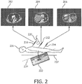
- FIG. 2 a diagram shows an example of plane registration misalignment error.
- Images 202, 204 and 206 depict CT cross-sections taken perpendicularly to an axial direction (e.g., sagittal plane) of a patient 231 at locations 210, 212 and 214, respectively.
- a sagittal slice 222 through the use of CT is depicted for reference.
- An ultrasonic probe 220 is employed to obtain ultrasonic images in real-time. While conventional plane registration can be accomplished rapidly, it is prone to errors and may not be usable with CT or MR acquisitions (202, 204 and 206) away from the plane where the registration is performed (212) on the patient 231. This is because a small angular error in the ultrasound transducer when defining the axial plane results in increasing spatial mismatch the further one goes away from the registration location (212).
- MR acquisitions are typically done in an oblique orientation. As such, even if the operator takes care to ensure that the ultrasound probe is perpendicular to the patient's position, alignment between the ultrasound plane and the acquisition plane of the MR may not be achieved.
- the user has to hold the ultrasound probe 220 to provide a scan plane that is parallel to an axial plane 232 (or perpendicular to the patient's body) when scanning the patient. Any deviations from parallel result in increasing registration errors when going further away from the registration location, that is, traveling along a rotated axial plane 234 corresponding with the orientation of the probe 220. A small deviation from being perfectly perpendicular to the patient's body is very difficult to detect visually, especially since the abdomen is a curved surface.
- any ultrasound scans overlaid onto the CT will be several centimeters lower (posterior direction) than the corresponding CT image. The opposite happens towards the head.
- An ultrasound scan shows up several centimeters above (anterior direction) the corresponding CT image.
- the imaging mechanism 134 provides live ultrasound images 122 in both an axial plane and a sagittal plane (or other sets of orthogonal or non-orthogonal planes). Plane alignment is performed for images 128 of the second imaging modality (e.g., CT, MR, etc.) to images 122 of the first imaging modality (e.g., ultrasound). Concurrent visualization of the images 122 and 128 in multiple planes immediately highlights any tilt in the alignment. This tilt is visualized and corrected immediately by, e.g., adjusting the alignment mechanism 132 until the sagittal planes of the ultrasound (122) and CT (128) are aligned. Aside from a tilt, if there were any error in the head-toe direction, the sagittal plane would highlight that offset and allow the user to correct for it.
- the second imaging modality e.g., CT, MR, etc.
- Concurrent visualization of the images 122 and 128 in multiple planes immediately highlights any tilt in the alignment. This tilt is visualized and corrected immediately by,
- coronal plane may be employed as well.
- a concurrent live ultrasound plane could be generated in the coronal dimension that could be used to identify and correct for errors in alignment in that orientation.
- Other plane orientations are also contemplated.
- the angle of the oblique acquisition is stored in the DICOM header. That value could be read by the ultrasound or other real-time imaging system, and applied to the acquisition of the X-planes such that the X-planes have that same oblique angle applied. This ensures that a clinical user could follow a consistent protocol for registration ("always place your probe perpendicular to the patient") instead of having to take into account the orientation of the CT or MR acquisition from patient to patient.
- the present principles may employ one or more additional planes to not only eliminate registration and angle errors but also provide improved targeting of points of interest (e.g., lesions).
- One purpose of image fusion and navigation is to enable very precise targeting (tool guidance) of, e.g., lesions using image data from multiple modalities.
- other tracking technologies may be employed, e.g., electromagnetic (EM) tracking information may be used for the needles in addition to ultrasound guidance.
- EM electromagnetic
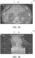
- an image 352 is shown having a CT image fused with an ultrasound image in an axial plane.
- the scan plane of the ultrasound and the reformatted CT appear to be going through the center of a large lesion, and that location is then marked with T1.
- T1 in an image 354 is located significantly off-center such that T1 is not actually in the middle of a lesion 356.
- This error is corrected by providing real-time image tracking of multiple planes concurrently as described.
- the present principles provide for improved guidance accuracy, by employing multiple plane visualizations of common features.
- Images 360 and 362 depict CT cross-sections taken axially (image 360) and perpendicularly to an axial direction (sagittal plane) (image 362) at a location on the patient 231.
- An ultrasonic probe 364 e.g., a 3D electronic probe (134) is employed to obtain an axial ultrasonic image 366 (dashed lines) and a sagittal ultrasonic image 368 (dashed lines) concurrently and in real-time.
- a slight tilt (arrow "A") along the axial direction results in the real-time image being misaligned in the axial direction (image 366 not aligned with image 360) and results in misalignment in the sagittal plane (images 368 and 362 are not aligned).
- the user can visually correct the misaligned images by moving the probe 364, which is also employed as an alignment mechanism, until the misalignment is removed (e.g., image 366 is aligned with image 360, and image 368 is aligned with image 362).
- a tilt 365 or other error is visualized and corrected immediately by angling the probe 364 until the axial planes and/or sagittal planes (or other planes) of the ultrasound and CT are aligned.
- the angle of the oblique acquisition e.g., stored in the DICOM header, could be read by the ultrasound or other real-time imaging system, and applied to the acquisition of the X-planes such that the X-planes have that same oblique angle applied.
- points may be selected using an interface that are common to the multiple planes. The common points may then be employed for visual alignment in the multiple planes.
- correct alignment is achieved by moving the probe 364 (or other devices) to a position that achieves alignment in at least two planes between the ultrasonic images 366 and 368 and images 360 and 362, respectively.
- alignment is made in at least two directions/planes, e.g., axial and sagittal, axial, and coronal, sagittal and coronal or between any other planes, registration is locked in, and guidance or other operations may proceed using fused or registered data to ensure proper positioning and/or trajectories of medical instruments.
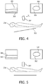
- example images 402, 404, 406 and 408 are illustratively shown.
- An upper left image 402 shows a live axial plane from an electronic 3D probe.
- a lower left image 404 shows the same axial plane fused with a CT image.
- An upper right image 406 and a lower right image 408 show the live sagittal plane and that same plane fused with the sagittal slice from the CT, respectively.
- the system 100 displays live ultrasound images in two or more planes (e.g., both the axial plane and the sagittal plane).
- the CT or MR of the patient is displayed sliced also axially and sagittally and displayed with their respective ultrasound image.
- both the axial images are overlaid with each other, and both sagittal images are overlaid with each other. If the sagittal images demonstrate an offset or some angular rotation relative to each other, the user can immediately physically correct for that tilt before locking in that registration.
- the embodiments described may employ the use of additional planes including but not limited to a coronal plane, etc., in addition to other planes including intermediary planes.
- an imaging and alignment apparatus associated with a first imaging modality is positioned to concurrently provide images in at least two imaging planes for a subject.
- the first modality may include ultrasonic imaging, and the apparatus may include an integrated imaging mechanism and alignment mechanism, such as an electronic three-dimensional probe.
- a three-dimensional (3D) image volume may be collected to generate the first images corresponding with imaging planes.
- the apparatus includes an alignment mechanism that may include an interface (e.g., 120, FIG. 1 ) for assigning displayable points common to the at least two imaging planes.
- second images are provided (e.g., generated or provided from memory) corresponding to the at least two imaging planes by reformatting a volume of image data acquired by a second imaging modality.
- first images are processed for the first imaging modality and second images collected are processed for the second imaging modality to permit user alignment between the first images and the second images in multiple planes.
- processing may include determining a center (or other position) of a point of interest using images from multiple planes.
- the images are manipulated to achieve alignment between corresponding first and second images in the multiple planes.
- the alignment process is preferably visual and provided to the user on a display or displays.
- the alignment can be performed by user manipulation of the alignment mechanism (e.g., probe) with visual feedback from one or more displays showing two or more planes.
- alignment may be achieved by selecting points (e.g., using an interface) in the first images and/or the second images to concurrently align corresponding points in each of multiple image planes in block 514.
- Other alignment operations may include aligning reference line, aligning markers, etc.
- the second modality may include computed tomography, magnetic resonance, etc. and processing may include adjusting the first modality images in accordance with an acquisition angle for the second images.
- registration between the first images with corresponding second images in the multiple planes is locked in when alignment in the multiple planes has been achieved.
- registering may include fusing the first and second images and further registering live images to fused first and second images.
- the fused/registered images may be employed for device guidance or other applications.
- the multi-planar fused images may be employed to guide one or more instruments during a procedure.
- the image fusion/registration may be employed in image guided interventional procedures, e.g., PercuNavTM.
- device guidance and tissue characterization may be performed in accordance with FIG. 8 .
- real-time images are acquired with a first modality in at least two imaging planes.
- the first modality may include ultrasonic imaging, etc.
- the second modality may include one or more of computed tomography (CT), magnetic resonance (MR), positron emission tomography (PET), single photon emission computed tomography (SPECT), cone-beam CT, tomosynthesis, a stored ultrasound volume, etc.
- CT computed tomography
- MR magnetic resonance
- PET positron emission tomography
- SPECT single photon emission computed tomography
- cone-beam CT tomosynthesis
- tomosynthesis a stored ultrasound volume, etc.
- the real-time images are fused with second images collected with a second imaging modality that correspond to the real-time images in the at least two imaging planes to generate fused images.
- fused images may be employed, and real-time images may be registered to the fused images.
- an instrument is guided by concurrently visualizing the fused images in the at least two imaging planes to position the instrument during a procedure.
- the instrument may include a needle guided to a target, which is visualized in multiple planes. The multi-plane positioning ensures better accuracy and instills operator confidence in the device positioning process.
- a point or points of interest may be characterized in the fused images.
- the point of interest may include an anatomical feature, a lesion, tumor, tissue, etc.
- the characterizing may include determining a center or other position on the point of interest using images from multiple planes.
- the procedure is continued, as needed.
Landscapes
- Health & Medical Sciences (AREA)
- Life Sciences & Earth Sciences (AREA)
- Engineering & Computer Science (AREA)
- Medical Informatics (AREA)
- Physics & Mathematics (AREA)
- Nuclear Medicine, Radiotherapy & Molecular Imaging (AREA)
- Surgery (AREA)
- Public Health (AREA)
- Biomedical Technology (AREA)
- Heart & Thoracic Surgery (AREA)
- Pathology (AREA)
- Molecular Biology (AREA)
- Biophysics (AREA)
- Animal Behavior & Ethology (AREA)
- General Health & Medical Sciences (AREA)
- Radiology & Medical Imaging (AREA)
- Veterinary Medicine (AREA)
- High Energy & Nuclear Physics (AREA)
- Computer Vision & Pattern Recognition (AREA)
- Optics & Photonics (AREA)
- Pulmonology (AREA)
- Theoretical Computer Science (AREA)
- Ultra Sonic Daignosis Equipment (AREA)
- Apparatus For Radiation Diagnosis (AREA)
- Magnetic Resonance Imaging Apparatus (AREA)
Applications Claiming Priority (2)
| Application Number | Priority Date | Filing Date | Title |
|---|---|---|---|
| US201461950880P | 2014-03-11 | 2014-03-11 | |
| PCT/IB2015/050948 WO2015136392A1 (en) | 2014-03-11 | 2015-02-09 | Image registration and guidance using concurrent x-plane imaging |
Publications (2)
| Publication Number | Publication Date |
|---|---|
| EP3116403A1 EP3116403A1 (en) | 2017-01-18 |
| EP3116403B1 true EP3116403B1 (en) | 2019-11-13 |
Family
ID=52727181
Family Applications (1)
| Application Number | Title | Priority Date | Filing Date |
|---|---|---|---|
| EP15711828.2A Active EP3116403B1 (en) | 2014-03-11 | 2015-02-09 | Image registration and guidance using concurrent x-plane imaging |
Country Status (5)
| Country | Link |
|---|---|
| US (1) | US10912537B2 (zh) |
| EP (1) | EP3116403B1 (zh) |
| JP (3) | JP2017511728A (zh) |
| CN (1) | CN106163408B (zh) |
| WO (1) | WO2015136392A1 (zh) |
Families Citing this family (19)
| Publication number | Priority date | Publication date | Assignee | Title |
|---|---|---|---|---|
| CN106462967B (zh) * | 2014-05-14 | 2020-06-30 | 皇家飞利浦有限公司 | 用于超声图像的基于模型的分割的采集取向相关特征 |
| US10966688B2 (en) * | 2014-08-26 | 2021-04-06 | Rational Surgical Solutions, Llc | Image registration for CT or MR imagery and ultrasound imagery using mobile device |
| WO2016175758A2 (en) | 2015-04-28 | 2016-11-03 | Analogic Corporation | Image guided steering of a transducer array and/or an instrument |
| JP6632361B2 (ja) * | 2015-12-15 | 2020-01-22 | キヤノン株式会社 | 画像処理装置、画像処理システム、画像処理方法、及びプログラム。 |
| KR20180066781A (ko) | 2016-12-09 | 2018-06-19 | 삼성전자주식회사 | 의료 영상을 표시하는 방법 및 장치 |
| EP3582709A4 (en) * | 2017-02-14 | 2020-11-25 | Intuitive Surgical Operations Inc. | MULTIDIMENSIONAL VISUALIZATION IN A COMPUTER-ASSISTED REMOTE-GUIDED SURGERY |
| US10299764B2 (en) * | 2017-05-10 | 2019-05-28 | General Electric Company | Method and system for enhanced visualization of moving structures with cross-plane ultrasound images |
| WO2018218424A1 (en) | 2017-05-27 | 2018-12-06 | Shanghai United Imaging Healthcare Co., Ltd. | System and method for couch sag compensation in image guided radio therapy |
| US10748345B2 (en) * | 2017-07-07 | 2020-08-18 | Adobe Inc. | 3D object composition as part of a 2D digital image through use of a visual guide |
| WO2019041538A1 (zh) * | 2017-11-02 | 2019-03-07 | 西安大医集团有限公司 | 肿瘤追踪方法及装置、放疗系统、存储介质 |
| US20210251696A1 (en) * | 2018-05-18 | 2021-08-19 | Koninklijke Phips N.V. | Mutli-modal image registration |
| CN109727223B (zh) * | 2018-12-27 | 2021-02-05 | 上海联影医疗科技股份有限公司 | 一种医学图像自动融合方法和系统 |
| CN110169783A (zh) * | 2019-07-08 | 2019-08-27 | 闫俊梁 | 一种数字化Pet-超声一体机 |
| WO2021049658A1 (ja) * | 2019-09-13 | 2021-03-18 | 出光興産株式会社 | 有機エレクトロルミネッセンス素子及び電子機器 |
| CN114760927A (zh) * | 2019-09-27 | 2022-07-15 | 布弗莱运营公司 | 提供用于定位超声设备的反馈的方法和装置 |
| WO2021159519A1 (zh) | 2020-02-14 | 2021-08-19 | 西安大医集团股份有限公司 | 图像引导方法、装置、放疗设备和计算机存储介质 |
| US11514624B2 (en) * | 2020-03-16 | 2022-11-29 | GE Precision Healthcare LLC | Methods and systems for biopsy needle reconstruction error assessment |
| EP4178446A4 (en) * | 2020-08-10 | 2023-06-07 | Shanghai United Imaging Healthcare Co., Ltd. | IMAGING SYSTEMS AND METHODS |
| CN113495099B (zh) * | 2021-09-08 | 2021-12-07 | 之江实验室 | 一种校正超声扫描显微镜样品倾斜的图像处理方法 |
Family Cites Families (17)
| Publication number | Priority date | Publication date | Assignee | Title |
|---|---|---|---|---|
| KR20030058423A (ko) * | 2001-12-31 | 2003-07-07 | 주식회사 메디슨 | 중재적 초음파를 사용하는 3 차원 초음파 진단 시스템에서검침 도구의 관찰 및 이의 대상체로의 진입을 용이하게하기 위한 방법 및 장치 |
| WO2005083629A1 (en) | 2004-02-20 | 2005-09-09 | Philips Intellectual Property & Standards Gmbh | Device and process for multimodal registration of images |
| US20060020204A1 (en) | 2004-07-01 | 2006-01-26 | Bracco Imaging, S.P.A. | System and method for three-dimensional space management and visualization of ultrasound data ("SonoDEX") |
| DE602004015796D1 (de) * | 2004-10-01 | 2008-09-25 | Medcom Ges Fuer Medizinische B | Registrierung eines Ultraschallbildes mit einem Bild aus einem 3D-Scan, beispielsweise von einer Computertomographie (CT) oder Magnetspintomographie (MR) |
| JP5543681B2 (ja) * | 2006-03-15 | 2014-07-09 | 株式会社日立メディコ | 超音波診断装置 |
| US8731264B2 (en) | 2006-11-27 | 2014-05-20 | Koninklijke Philips N.V. | System and method for fusing real-time ultrasound images with pre-acquired medical images |
| EP1933278A1 (en) | 2006-12-14 | 2008-06-18 | BrainLAB AG | Image fusion visualisation |
| DE102006061178A1 (de) | 2006-12-22 | 2008-06-26 | Siemens Ag | System zur Durchführung und Überwachung minimal-invasiver Eingriffe |
| WO2010125505A1 (en) * | 2009-04-28 | 2010-11-04 | Koninklijke Philips Electronics N.V. | Biopsy guide system with an ultrasound transducer and method of using same |
| KR101121353B1 (ko) | 2009-08-03 | 2012-03-09 | 한국과학기술원 | 2차원 초음파 영상에 대응하는 2차원 ct 영상을 제공하는 시스템 및 방법 |
| WO2011063517A1 (en) | 2009-11-27 | 2011-06-03 | Sentinelle Medical Inc. | Systems and methods for tracking positions between imaging modalities and transforming a displayed three-dimensional image corresponding to a position and orientation of a probe |
| JP2011167330A (ja) | 2010-02-18 | 2011-09-01 | Ge Medical Systems Global Technology Co Llc | 超音波診断装置 |
| BR112013031869B1 (pt) | 2011-06-16 | 2021-05-18 | Koninklijke Philips N.V. | sistema e método para a geração de um mapa de registro de imagem, sistema de planejamento de terapia, um ou mais processadores, e, meio legível por computador não transitório |
| US9715757B2 (en) | 2012-05-31 | 2017-07-25 | Koninklijke Philips N.V. | Ultrasound imaging system and method for image guidance procedure |
| WO2014003071A1 (ja) * | 2012-06-27 | 2014-01-03 | 株式会社東芝 | 超音波診断装置及び画像データの補正方法 |
| US20140135623A1 (en) * | 2012-11-15 | 2014-05-15 | General Electric Company | Systems and methods for x-ray and ultrasound imaging |
| US9230331B2 (en) * | 2013-10-21 | 2016-01-05 | Samsung Electronics Co., Ltd. | Systems and methods for registration of ultrasound and CT images |
-
2015
- 2015-02-09 EP EP15711828.2A patent/EP3116403B1/en active Active
- 2015-02-09 JP JP2016555957A patent/JP2017511728A/ja active Pending
- 2015-02-09 US US15/118,217 patent/US10912537B2/en active Active
- 2015-02-09 WO PCT/IB2015/050948 patent/WO2015136392A1/en active Application Filing
- 2015-02-09 CN CN201580012710.9A patent/CN106163408B/zh active Active
-
2020
- 2020-12-23 JP JP2020213036A patent/JP2021049416A/ja active Pending
-
2023
- 2023-02-09 JP JP2023018321A patent/JP2023053108A/ja active Pending
Non-Patent Citations (1)
| Title |
|---|
| None * |
Also Published As
| Publication number | Publication date |
|---|---|
| US10912537B2 (en) | 2021-02-09 |
| JP2023053108A (ja) | 2023-04-12 |
| CN106163408B (zh) | 2020-01-07 |
| CN106163408A (zh) | 2016-11-23 |
| JP2021049416A (ja) | 2021-04-01 |
| WO2015136392A1 (en) | 2015-09-17 |
| US20170164931A1 (en) | 2017-06-15 |
| JP2017511728A (ja) | 2017-04-27 |
| EP3116403A1 (en) | 2017-01-18 |
Similar Documents
| Publication | Publication Date | Title |
|---|---|---|
| EP3116403B1 (en) | Image registration and guidance using concurrent x-plane imaging | |
| EP3206619B1 (en) | Navigation of a surgical instrument | |
| EP2963616B1 (en) | Fluoroscopic pose estimation | |
| US8781186B2 (en) | System and method for abdominal surface matching using pseudo-features | |
| US8165660B2 (en) | System and method for selecting a guidance mode for performing a percutaneous procedure | |
| US6379302B1 (en) | Navigation information overlay onto ultrasound imagery | |
| JP5683065B2 (ja) | 容積式位置揃えのための改良型システム及び方法 | |
| US20150230689A1 (en) | Method for Assisting Navigation of an Endoscopic Device | |
| US20140243658A1 (en) | Computer-Implemented Technique for Calculating a Position of a Surgical Device | |
| US20080300477A1 (en) | System and method for correction of automated image registration | |
| US10849694B2 (en) | Method and system for displaying the position and orientation of a linear instrument navigated with respect to a 3D medical image | |
| US20050004449A1 (en) | Method for marker-less navigation in preoperative 3D images using an intraoperatively acquired 3D C-arm image | |
| US20070118100A1 (en) | System and method for improved ablation of tumors | |
| KR101954868B1 (ko) | 혈관 중재 시술을 위한 내비게이션 시스템 및 가상의 엑스선 이미지 생성 방법 | |
| US20140147027A1 (en) | Intra-operative image correction for image-guided interventions | |
| US20180168735A1 (en) | Methods for improving patient registration | |
| Hartov et al. | Adaptive spatial calibration of a 3D ultrasound system | |
| Shahin et al. | Ultrasound-based tumor movement compensation during navigated laparoscopic liver interventions | |
| EP3931799B1 (en) | Interventional device tracking | |
| Vandermeulen et al. | Prototype medical workstation for computer-assisted stereotactic neurosurgery | |
| Estépar et al. | Multimodality guidance in endoscopic and laparoscopic abdominal procedures | |
| WO2024002476A1 (en) | Determining electrode orientation using optimized imaging parameters |
Legal Events
| Date | Code | Title | Description |
|---|---|---|---|
| PUAI | Public reference made under article 153(3) epc to a published international application that has entered the european phase |
Free format text: ORIGINAL CODE: 0009012 |
|
| STAA | Information on the status of an ep patent application or granted ep patent |
Free format text: STATUS: REQUEST FOR EXAMINATION WAS MADE |
|
| 17P | Request for examination filed |
Effective date: 20161011 |
|
| AK | Designated contracting states |
Kind code of ref document: A1 Designated state(s): AL AT BE BG CH CY CZ DE DK EE ES FI FR GB GR HR HU IE IS IT LI LT LU LV MC MK MT NL NO PL PT RO RS SE SI SK SM TR |
|
| AX | Request for extension of the european patent |
Extension state: BA ME |
|
| DAX | Request for extension of the european patent (deleted) | ||
| GRAP | Despatch of communication of intention to grant a patent |
Free format text: ORIGINAL CODE: EPIDOSNIGR1 |
|
| STAA | Information on the status of an ep patent application or granted ep patent |
Free format text: STATUS: GRANT OF PATENT IS INTENDED |
|
| INTG | Intention to grant announced |
Effective date: 20190605 |
|
| GRAS | Grant fee paid |
Free format text: ORIGINAL CODE: EPIDOSNIGR3 |
|
| GRAA | (expected) grant |
Free format text: ORIGINAL CODE: 0009210 |
|
| STAA | Information on the status of an ep patent application or granted ep patent |
Free format text: STATUS: THE PATENT HAS BEEN GRANTED |
|
| AK | Designated contracting states |
Kind code of ref document: B1 Designated state(s): AL AT BE BG CH CY CZ DE DK EE ES FI FR GB GR HR HU IE IS IT LI LT LU LV MC MK MT NL NO PL PT RO RS SE SI SK SM TR |
|
| REG | Reference to a national code |
Ref country code: CH Ref legal event code: EP Ref country code: AT Ref legal event code: REF Ref document number: 1200840 Country of ref document: AT Kind code of ref document: T Effective date: 20191115 |
|
| REG | Reference to a national code |
Ref country code: DE Ref legal event code: R096 Ref document number: 602015041579 Country of ref document: DE |
|
| REG | Reference to a national code |
Ref country code: IE Ref legal event code: FG4D |
|
| REG | Reference to a national code |
Ref country code: DE Ref legal event code: R084 Ref document number: 602015041579 Country of ref document: DE |
|
| REG | Reference to a national code |
Ref country code: GB Ref legal event code: 746 Effective date: 20200210 |
|
| RAP2 | Party data changed (patent owner data changed or rights of a patent transferred) |
Owner name: KONINKLIJKE PHILIPS N.V. |
|
| REG | Reference to a national code |
Ref country code: NL Ref legal event code: MP Effective date: 20191113 |
|
| REG | Reference to a national code |
Ref country code: LT Ref legal event code: MG4D |
|
| PG25 | Lapsed in a contracting state [announced via postgrant information from national office to epo] |
Ref country code: BG Free format text: LAPSE BECAUSE OF FAILURE TO SUBMIT A TRANSLATION OF THE DESCRIPTION OR TO PAY THE FEE WITHIN THE PRESCRIBED TIME-LIMIT Effective date: 20200213 Ref country code: FI Free format text: LAPSE BECAUSE OF FAILURE TO SUBMIT A TRANSLATION OF THE DESCRIPTION OR TO PAY THE FEE WITHIN THE PRESCRIBED TIME-LIMIT Effective date: 20191113 Ref country code: NL Free format text: LAPSE BECAUSE OF FAILURE TO SUBMIT A TRANSLATION OF THE DESCRIPTION OR TO PAY THE FEE WITHIN THE PRESCRIBED TIME-LIMIT Effective date: 20191113 Ref country code: SE Free format text: LAPSE BECAUSE OF FAILURE TO SUBMIT A TRANSLATION OF THE DESCRIPTION OR TO PAY THE FEE WITHIN THE PRESCRIBED TIME-LIMIT Effective date: 20191113 Ref country code: PL Free format text: LAPSE BECAUSE OF FAILURE TO SUBMIT A TRANSLATION OF THE DESCRIPTION OR TO PAY THE FEE WITHIN THE PRESCRIBED TIME-LIMIT Effective date: 20191113 Ref country code: LV Free format text: LAPSE BECAUSE OF FAILURE TO SUBMIT A TRANSLATION OF THE DESCRIPTION OR TO PAY THE FEE WITHIN THE PRESCRIBED TIME-LIMIT Effective date: 20191113 Ref country code: NO Free format text: LAPSE BECAUSE OF FAILURE TO SUBMIT A TRANSLATION OF THE DESCRIPTION OR TO PAY THE FEE WITHIN THE PRESCRIBED TIME-LIMIT Effective date: 20200213 Ref country code: PT Free format text: LAPSE BECAUSE OF FAILURE TO SUBMIT A TRANSLATION OF THE DESCRIPTION OR TO PAY THE FEE WITHIN THE PRESCRIBED TIME-LIMIT Effective date: 20200313 Ref country code: GR Free format text: LAPSE BECAUSE OF FAILURE TO SUBMIT A TRANSLATION OF THE DESCRIPTION OR TO PAY THE FEE WITHIN THE PRESCRIBED TIME-LIMIT Effective date: 20200214 Ref country code: LT Free format text: LAPSE BECAUSE OF FAILURE TO SUBMIT A TRANSLATION OF THE DESCRIPTION OR TO PAY THE FEE WITHIN THE PRESCRIBED TIME-LIMIT Effective date: 20191113 |
|
| PG25 | Lapsed in a contracting state [announced via postgrant information from national office to epo] |
Ref country code: IS Free format text: LAPSE BECAUSE OF FAILURE TO SUBMIT A TRANSLATION OF THE DESCRIPTION OR TO PAY THE FEE WITHIN THE PRESCRIBED TIME-LIMIT Effective date: 20200313 Ref country code: HR Free format text: LAPSE BECAUSE OF FAILURE TO SUBMIT A TRANSLATION OF THE DESCRIPTION OR TO PAY THE FEE WITHIN THE PRESCRIBED TIME-LIMIT Effective date: 20191113 Ref country code: RS Free format text: LAPSE BECAUSE OF FAILURE TO SUBMIT A TRANSLATION OF THE DESCRIPTION OR TO PAY THE FEE WITHIN THE PRESCRIBED TIME-LIMIT Effective date: 20191113 |
|
| PG25 | Lapsed in a contracting state [announced via postgrant information from national office to epo] |
Ref country code: AL Free format text: LAPSE BECAUSE OF FAILURE TO SUBMIT A TRANSLATION OF THE DESCRIPTION OR TO PAY THE FEE WITHIN THE PRESCRIBED TIME-LIMIT Effective date: 20191113 |
|
| PG25 | Lapsed in a contracting state [announced via postgrant information from national office to epo] |
Ref country code: DK Free format text: LAPSE BECAUSE OF FAILURE TO SUBMIT A TRANSLATION OF THE DESCRIPTION OR TO PAY THE FEE WITHIN THE PRESCRIBED TIME-LIMIT Effective date: 20191113 Ref country code: EE Free format text: LAPSE BECAUSE OF FAILURE TO SUBMIT A TRANSLATION OF THE DESCRIPTION OR TO PAY THE FEE WITHIN THE PRESCRIBED TIME-LIMIT Effective date: 20191113 Ref country code: ES Free format text: LAPSE BECAUSE OF FAILURE TO SUBMIT A TRANSLATION OF THE DESCRIPTION OR TO PAY THE FEE WITHIN THE PRESCRIBED TIME-LIMIT Effective date: 20191113 Ref country code: RO Free format text: LAPSE BECAUSE OF FAILURE TO SUBMIT A TRANSLATION OF THE DESCRIPTION OR TO PAY THE FEE WITHIN THE PRESCRIBED TIME-LIMIT Effective date: 20191113 Ref country code: CZ Free format text: LAPSE BECAUSE OF FAILURE TO SUBMIT A TRANSLATION OF THE DESCRIPTION OR TO PAY THE FEE WITHIN THE PRESCRIBED TIME-LIMIT Effective date: 20191113 |
|
| REG | Reference to a national code |
Ref country code: DE Ref legal event code: R097 Ref document number: 602015041579 Country of ref document: DE |
|
| REG | Reference to a national code |
Ref country code: AT Ref legal event code: MK05 Ref document number: 1200840 Country of ref document: AT Kind code of ref document: T Effective date: 20191113 |
|
| PG25 | Lapsed in a contracting state [announced via postgrant information from national office to epo] |
Ref country code: SM Free format text: LAPSE BECAUSE OF FAILURE TO SUBMIT A TRANSLATION OF THE DESCRIPTION OR TO PAY THE FEE WITHIN THE PRESCRIBED TIME-LIMIT Effective date: 20191113 Ref country code: SK Free format text: LAPSE BECAUSE OF FAILURE TO SUBMIT A TRANSLATION OF THE DESCRIPTION OR TO PAY THE FEE WITHIN THE PRESCRIBED TIME-LIMIT Effective date: 20191113 |
|
| PLBE | No opposition filed within time limit |
Free format text: ORIGINAL CODE: 0009261 |
|
| STAA | Information on the status of an ep patent application or granted ep patent |
Free format text: STATUS: NO OPPOSITION FILED WITHIN TIME LIMIT |
|
| REG | Reference to a national code |
Ref country code: CH Ref legal event code: PL |
|
| 26N | No opposition filed |
Effective date: 20200814 |
|
| REG | Reference to a national code |
Ref country code: BE Ref legal event code: MM Effective date: 20200229 |
|
| PG25 | Lapsed in a contracting state [announced via postgrant information from national office to epo] |
Ref country code: LU Free format text: LAPSE BECAUSE OF NON-PAYMENT OF DUE FEES Effective date: 20200209 Ref country code: MC Free format text: LAPSE BECAUSE OF FAILURE TO SUBMIT A TRANSLATION OF THE DESCRIPTION OR TO PAY THE FEE WITHIN THE PRESCRIBED TIME-LIMIT Effective date: 20191113 |
|
| PG25 | Lapsed in a contracting state [announced via postgrant information from national office to epo] |
Ref country code: LI Free format text: LAPSE BECAUSE OF NON-PAYMENT OF DUE FEES Effective date: 20200229 Ref country code: AT Free format text: LAPSE BECAUSE OF FAILURE TO SUBMIT A TRANSLATION OF THE DESCRIPTION OR TO PAY THE FEE WITHIN THE PRESCRIBED TIME-LIMIT Effective date: 20191113 Ref country code: CH Free format text: LAPSE BECAUSE OF NON-PAYMENT OF DUE FEES Effective date: 20200229 Ref country code: SI Free format text: LAPSE BECAUSE OF FAILURE TO SUBMIT A TRANSLATION OF THE DESCRIPTION OR TO PAY THE FEE WITHIN THE PRESCRIBED TIME-LIMIT Effective date: 20191113 |
|
| PG25 | Lapsed in a contracting state [announced via postgrant information from national office to epo] |
Ref country code: IE Free format text: LAPSE BECAUSE OF NON-PAYMENT OF DUE FEES Effective date: 20200209 Ref country code: IT Free format text: LAPSE BECAUSE OF FAILURE TO SUBMIT A TRANSLATION OF THE DESCRIPTION OR TO PAY THE FEE WITHIN THE PRESCRIBED TIME-LIMIT Effective date: 20191113 |
|
| PG25 | Lapsed in a contracting state [announced via postgrant information from national office to epo] |
Ref country code: BE Free format text: LAPSE BECAUSE OF NON-PAYMENT OF DUE FEES Effective date: 20200229 |
|
| PG25 | Lapsed in a contracting state [announced via postgrant information from national office to epo] |
Ref country code: TR Free format text: LAPSE BECAUSE OF FAILURE TO SUBMIT A TRANSLATION OF THE DESCRIPTION OR TO PAY THE FEE WITHIN THE PRESCRIBED TIME-LIMIT Effective date: 20191113 Ref country code: MT Free format text: LAPSE BECAUSE OF FAILURE TO SUBMIT A TRANSLATION OF THE DESCRIPTION OR TO PAY THE FEE WITHIN THE PRESCRIBED TIME-LIMIT Effective date: 20191113 Ref country code: CY Free format text: LAPSE BECAUSE OF FAILURE TO SUBMIT A TRANSLATION OF THE DESCRIPTION OR TO PAY THE FEE WITHIN THE PRESCRIBED TIME-LIMIT Effective date: 20191113 |
|
| PG25 | Lapsed in a contracting state [announced via postgrant information from national office to epo] |
Ref country code: MK Free format text: LAPSE BECAUSE OF FAILURE TO SUBMIT A TRANSLATION OF THE DESCRIPTION OR TO PAY THE FEE WITHIN THE PRESCRIBED TIME-LIMIT Effective date: 20191113 |
|
| PGFP | Annual fee paid to national office [announced via postgrant information from national office to epo] |
Ref country code: FR Payment date: 20230223 Year of fee payment: 9 |
|
| PGFP | Annual fee paid to national office [announced via postgrant information from national office to epo] |
Ref country code: DE Payment date: 20240228 Year of fee payment: 10 Ref country code: GB Payment date: 20240220 Year of fee payment: 10 |