EP3116292B1 - Elektronikmodul mit generativ erzeugtem kühlkörper - Google Patents
Elektronikmodul mit generativ erzeugtem kühlkörper Download PDFInfo
- Publication number
- EP3116292B1 EP3116292B1 EP15175536.0A EP15175536A EP3116292B1 EP 3116292 B1 EP3116292 B1 EP 3116292B1 EP 15175536 A EP15175536 A EP 15175536A EP 3116292 B1 EP3116292 B1 EP 3116292B1
- Authority
- EP
- European Patent Office
- Prior art keywords
- channel
- heat sink
- cooling
- channels
- electronic module
- Prior art date
- Legal status (The legal status is an assumption and is not a legal conclusion. Google has not performed a legal analysis and makes no representation as to the accuracy of the status listed.)
- Active
Links
Images


Classifications
-
- H—ELECTRICITY
- H05—ELECTRIC TECHNIQUES NOT OTHERWISE PROVIDED FOR
- H05K—PRINTED CIRCUITS; CASINGS OR CONSTRUCTIONAL DETAILS OF ELECTRIC APPARATUS; MANUFACTURE OF ASSEMBLAGES OF ELECTRICAL COMPONENTS
- H05K7/00—Constructional details common to different types of electric apparatus
- H05K7/20—Modifications to facilitate cooling, ventilating, or heating
- H05K7/2089—Modifications to facilitate cooling, ventilating, or heating for power electronics, e.g. for inverters for controlling motor
- H05K7/20927—Liquid coolant without phase change
Definitions
- the invention relates to an electronic module with a heat sink and electronic elements which are arranged distributed over a surface of the heat sink and are thermally coupled to the surface for cooling.
- the electronics module can in particular be an on-board charger, a DC-DC converter or an engine control device for a vehicle, preferably an electric or hybrid vehicle.
- a preferred field of application is automobile construction.
- the invention is particularly aimed at electric and hybrid automobiles.
- Power electronics generate high power losses and require cooling.
- the electronic components are therefore arranged on a heat sink through which a cooling fluid flows.
- an electronics module with a heat sink composed of two cooling structures is also known.
- the cooling structures are joined by means of a welded connection.
- Cooling fins protrude like the heat sink DE 10 2012 200 325 A1 in a uniform arrangement from one of the cooling structures and into a receiving space of the other cooling structure, so that the cooling fluid in the receiving space is evenly distributed over the heat exchange surface.
- the EP 0 838 988 A2 discloses an electronic module with electronic elements which are arranged for cooling on a heat sink which has a box-shaped cooling structure which is closed by a base plate on its side facing away from the electronic elements. Pins arranged in hexagonal symmetry protrude from the cooling structure in the direction of the base plate. The pins are arranged in pin groups according to the arrangement of the electronic elements to be cooled. The hollow space through which a flow can flow is further divided by a partition into two sub-spaces through which the flow passes in parallel. The The partition wall also protrudes from the cooling structure in the direction of the base plate.
- the cooling structure including the peg and partition, is cast from a metal-ceramic composite material.
- a particularly compact electronics module is from the DE 20 2009 007 008 U1 known. Like the electronics modules described above, the electronics module has a heat sink made up of substructures. The electronics module is characterized by a cooling circuit that is closed within the module and a fan-based heat dissipation integrated on the module.
- the EP 2 801 512 A1 discloses a heat sink hybrid, for the production of which a heat exchange structure is generatively formed on a prefabricated basic structure.
- a heat exchange structure is generatively formed on the side of a power electronics housing.
- the cooling structure has lattice-shaped or cellular heat exchange structures in the interior in a regularly repeating pattern. It is also mentioned that the cooling structure can have cooling channels in order to form a cooling system with a predetermined flow profile.
- the EP 1 484 954 A2 and the US 2012/085523 A1 each relate to a heat sink through which a cooling liquid can flow, for example to cool electronic parts connected to the heat sink.
- the heat sink comprises several liquid channels that are subsequently introduced into the heat sink blank, for example by drilling.
- the holes are horizontal and vertical through holes that form a connected duct network inside the heat sink. All bore openings, except for one inlet and one outlet, are closed so that no cooling liquid can escape through the closed openings.
- the EP 2 709 431 A1 relates to a heat sink, which consists of a frame-shaped housing and inserts that are inserted into the housing.
- the inserts include cooling fins on the side to be inserted into the housing.
- the cooling fins form a network of channels in the cooling body for a cooling liquid.
- the EP 2 808 986 A1 relates to a heat sink for a linear motor that can be produced using 3D printing.
- the invention is based on an electronics module with a heat sink through which a flow can flow and electronic elements which are arranged distributed over an outer surface on an upper side of the heat sink.
- This outer surface is referred to below as the top surface.
- the heat sink has an outer underside surface facing away from the upper-side surface.
- the upper surface and / or the lower surface can or can in particular be flat and parallel, which also includes that the heat sink can have a step-like offset on one or on both outer surfaces.
- the cooling body is plate-shaped and is particularly preferably a cooling plate in the narrower sense, i. H. a cooling cuboid with a flat top surface, a flat bottom surface and flat outer sides.
- the cooling cuboid can have one or more pocket-shaped openings or local incisions extending from one surface to the other surface.
- the electronic elements are electrically and / or optically connected in a first layout by means of conductor tracks and are thermally coupled to the upper surface of the cooling body for cooling, but are electrically isolated from the cooling body.
- the heat sink has one or more recesses in the upper surface, each in the form of a pocket, the bottom of the respective pocket is understood to belong to the upper surface.
- the cooling body can also have one or more recesses, each in the form of an opening, on the upper surface.
- the optionally one or optionally more recesses has or each have side surfaces which protrude from the surrounding area of the upper surface.
- One or more of the electronic elements can or can each be arranged upside down with respect to the heat sink.
- the respective overhead electronic element points away from the heat sink with its electrical contacts. If one or more electronic elements is or are arranged upside down, the relevant electronic element can be connected in a thermally conductive manner directly to the upper surface of the cooling body on its upper side facing away from the electrical contacts. If the heat sink has one or more recesses, the respective overhead electronic element can advantageously protrude into the recess, i.e. be buried in the heat sink.
- the respective buried electronic element protrudes into a pocket-shaped recess, it can be connected to the bottom and / or one or more side surfaces of the recess in a thermally conductive manner on its upper side and / or on one or more of its side surfaces. If the respective buried electronic element protrudes into a recess in the cooling body shaped as a breakthrough, it can be connected in a thermally conductive manner on one or more of its side surfaces to one or more side surfaces of the recess in question.
- the electronic elements can be arranged on a printed circuit board and this printed circuit board can be connected to the upper surface of the heat sink in a thermally conductive manner.
- the electronic elements can also be arranged directly on the upper surface and be connected to the surface in a thermally conductive manner. Designs are also possible in which one or more of the electronic elements are arranged on a printed circuit board and one or more of the other electronic elements are arranged directly on the upper surface of the heat sink.
- the thermal coupling can be implemented, for example, by means of a heat-conducting pad.
- the heat conducting pad can be adhesively coated on both sides for attachment to the circuit board and / or directly to electronic elements and for attachment to the heat sink. Instead of or in addition to an adhesive coating, a thermally conductive adhesive can also be applied for attachment.
- the cooling body has an inlet for a cooling fluid, an outlet for the cooling fluid and a channel system extending through the cooling body with channels branched inside the cooling body.
- the channel system connects the inlet with the outlet.
- the heat sink is a generatively produced monolith, i. H. a unit generated generatively as a whole in one piece. Due to the monolithic generative generation, the channel system can be adapted to the topographical distribution of the power losses and thus the heat generation of the electronic elements more precisely than was previously possible, for example with a cast heat sink. Due to the generatively monolithic production, the sealing of the heat sink is no longer a problem, since the heat sink is produced from the outset as a structure that is closed with respect to its outer surfaces, apart from the inlet and outlet, optionally also one or more further inlets and / or outlets . There are no manufacturing steps, since no heat sink parts have to be manufactured separately from one another and then joined. Geometrical errors in the duct system, which can occur during separate production and subsequent joining, are excluded.
- the cross-sections of the channels can be varied flexibly, on the one hand from channel to channel, on the other hand also over the course of the same channel in each case.
- Very fine heat conduction structures can be produced in the channels, in the form of cooling pins, cooling fins or cooling ribs that are elongated in the longitudinal direction of the respective channel.
- the inner surface of one, several or all of the channels is significantly larger than smooth surfaces by a structuring created during generative production in order to increase the heat transfer per unit area of the upper surface and / or to concentrate or to concentrate in certain areas according to the heat requirement increase.
- the heat sink generated generatively as a monolith according to the invention can be provided as a result with the same cooling performance in smaller external dimensions than a conventionally shaped and joined heat sink.
- the heat sink can in particular be designed with a small thickness, the thickness being measured parallel to the plan view of the upper surface.
- the invention also relates to a method for producing a heat sink for an electronic module, wherein the heat sink has an inlet for a cooling fluid, an outlet for the cooling fluid, a channel system running through the heat sink, a cover layer that is impermeable to the cooling fluid and has an outer top surface and one for the Cooling fluid-tight further cover layer with an outer underside surface.
- the upper side and / or the lower side surface can or can each be planar, at least essentially smooth surfaces.
- the upper surface and / or the lower surface can have one or more recesses.
- the respective recess can be shaped as a pocket let into the upper surface or the lower surface or as an opening extending from the upper surface to the lower surface.
- the heat sink can in particular be designed as described above.
- the heat sink as a whole is generated generatively by applying metal powder in powder bed layers and solidifying the metal powder of the respective powder bed layer.
- the metal powder is selectively solidified in the respective powder bed layer according to the geometry of the channel system, the inlet and the outlet by means of an energy beam, preferably a laser.
- the metal powder can in particular be melted for solidification by means of the energy beam.
- the metal powder of the respective powder bed layer is selectively solidified in accordance with the geometry of the cover layers by means of an energy beam, preferably laser, in order to tightly enclose the channel system between the cover layers.
- a single energy beam preferably a laser
- several energy beams can be used per powder bed layer or only in selected powder bed layers at the same time, i.e. acting in parallel in different powder bed areas.
- the cooling body is produced horizontally, in that one or more powder bed layers are or are solidified one after the other in accordance with one of the cover layers over the whole area by means of an energy beam in order to obtain one of the cover layers.
- the metal powder is selectively solidified by means of an energy beam in powder bed layers that are subsequently applied successively in accordance with the geometry of the duct system.
- the channels which are initially still open, are then closed by means of several successively applied and selectively solidified powder bed layers.
- one or more then still applied powder layers of the other top layer are correspondingly solidified over the entire area in order to obtain the other top layer.
- the layered body is thus built up in the direction of the other, viewed from one cover layer.
- the layer is built up in the thickness direction of the heat sink.
- the cooling body is built up in an upright position, in that the two cover layers mentioned are produced successively, powder bed layer by powder bed layer.
- the metal powder in the powder bed layers is selectively solidified in a powder strip corresponding to the cross section of the cooling body.
- the metal powder is selectively solidified by means of an energy beam in the outer powder strip areas of the respective cover layer and in the central powder strip area between the outer powder strip areas according to the geometry of the channel system.
- the heat sink is successively moved, layer by layer, in a planar direction of the upper surface, i. H. constructed from a side wall of the heat sink towards an opposite side wall.
- the heat sink can in particular consist of copper and / or aluminum and / or an alloy which contains copper and / or aluminum as essential components.
- a heat sink in particular can consist only of copper or only of aluminum, of a copper alloy, an aluminum alloy or a CuAl-based alloy.
- the generatively produced material of the heat sink can be homogeneous in terms of chemical composition over the entire heat sink.
- the generatively produced material can also be a gradient material.
- the chemical composition of the material can vary in a length direction and / or a width direction of the heat sink when viewed from above on the upper surface. More preferably, the material composition varies parallel to the plan view in the thickness direction of the heat sink.
- a material gradient can be set in particular in the direction of the generative layer structure by changing the chemical composition of the metal powder from one powder bed layer to the next.
- the composition of the metal powder can be changed successively over several powder bed layers, but in principle it is also conceivable to change the composition in a larger jump only once or in a few steps.
- a material gradient can readily be varied in the direction of progress of the layer structure, from one end of the upper surface in the direction of an opposite end of the upper surface.
- a layer structure that progresses in the direction of the thickness is more suitable, i.e. the generation of the heat sink lying down in accordance with the first method.
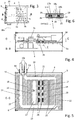
- FIG. 1 shows an electronic module just before assembly.
- the electronics module comprises a heat sink 10, which is sandwiched between electronic elements 3a and 3b of a first layout 1 and electronic elements 3c of a second layout 2 in order to cool the electronic elements of the respective layout 1 and 2 during operation of the electronic module.
- the cooling takes place actively in that a cooling fluid, preferably a cooling liquid, is conveyed through a channel system running through the cooling body 10 in the interior.
- a cooling fluid preferably a cooling liquid
- the cooling fluid flows through an inlet 13 of the cooling body 10 into the cooling body 10, flows through the inner channel system and is guided out of the cooling body 10 again through an outlet 14.
- the housing can be dust-tight and waterproof and in particular designed so that it meets the requirements of a Housing a power electronics in the engine compartment of an electric hybrid or purely electric vehicle meets, for example, the protection class IP6K6 or IP6K6K or IP6K9K.
- the housing is made up of several separately manufactured housing parts. It comprises a main housing part 4 which, in the assembled state, surrounds the heat sink 10 with the electronic elements 3a-3c, and a rear wall 5 which tightly closes the main housing part 4 on a rear side. On the front side, the main housing part 4 is closed by a front wall 6 in the assembled state.
- the cooling plate 10 can be firmly joined to the front wall 6, so that the heat sink 10 with the electronic elements 3a-3c can be pushed into the main housing part 4 and the front wall 6 pushed against the main housing part 4 in the same assembly step.
- the front wall 6 is firmly connected to the main housing part 4 in the next step.
- guide structures are provided in the area of the main housing part 4.
- guide structures for guiding the heat sink 10 are only provided in the front area of the main housing part 4.
- the guide structures for guiding the slide-in unit 6, 10 can be formed on a frame-shaped adapter structure 7 manufactured separately from the main housing part 4.
- the adapter structure 7, like the rear wall 5, is firmly joined to the correspondingly simplified main housing part 4.
- the rear wall 6 and / or the adapter structure 7 can each be joined to the main housing part 4 in a materially and thus dustproof and / or watertight manner, in particular by means of a welded connection, soldered connection, or adhesive connection.
- the front wall 6 is connected to the main housing part 4, preferably by means of a screw connection or metal clips, the adapter structure 7 for the main housing part 4 providing the joining elements required to produce such a connection, preferably screw elements such as screw holes in particular.
- the tightness is ensured by a housing seal 8 which is arranged between the adapter structure 7 and the front wall 6 in the joined state.
- the main housing part 4 can be manufactured inexpensively in series from a simple sheet metal blank by edging and subsequent welding, soldering or gluing if the guide structures for guiding the heat sink 10 and / or the fastening elements for fastening the front wall 6 are provided by a separately manufactured adapter structure 7.
- a main housing part 4 with integrated guide structures can be manufactured for example by extrusion.
- the optional adapter structure 7, which is used to position and guide the heat sink 10 during assembly, is preferably a cast part, but can also be manufactured, for example, by means of machining.
- the rear wall 5 preferably not only fulfills the function of a rear closure of the housing 4-7, but also a function in positioning and holding the cooling plate 10.
- a positioning structure 5a for the heat sink 10 can be formed on the inside of the rear wall 5 be, for example a groove or a protruding pair of ribs into or between which the heat sink 10 is inserted during assembly.
- the front wall 6 can in particular be a lasered or punched sheet metal, machined solid material or a cast part.
- the joined housing 4-7 is preferably designed as a metal housing. In principle, however, it can instead also be designed as a plastic housing or as a housing made up of metal parts and plastic parts.
- Connections 9 are arranged on the front wall 6, via which electrical energy and electrical and / or optical signals can be transmitted between the power electronics 3a-3c arranged on the heat sink 10 and one or more connected devices.
- the electronic elements 3a and 3b of the first layout 1 are arranged on an outer surface 11 on an upper side of the heat sink 10.
- the electronic elements 3c of the second layout 2 are arranged on an outer surface 12 on an underside of the heat sink 10.
- top side and bottom side are only intended to express that the heat sink 10 is arranged between the first layout 1 of electronic elements 3a and 3b and the second layout 2 of electronic elements 3c.
- top and bottom do not define the orientation of the heat sink 10 in space.
- the cooling body 10 is shaped as a thin cooling plate and, as is preferred, at least essentially as a flat cooling cuboid.
- the heat sink 10 accordingly has a thickness which is significantly less than a length and width measured in a plan view of the top.
- the length and width can each be more than ten times the thickness.
- the length and the width are each twenty times as great as the thickness.
- the electronic elements of the first layout 1 are arranged on a circuit board which is connected to the upper surface 11 in a thermally conductive manner by means of a heat-conducting pad 1 a.
- the electronic elements of the second layout are also arranged on a circuit board and connected to the underside surface 12 in a thermally conductive manner via a heat-conducting pad 2a.
- the circuit boards with the electronic elements 3a to 3c can also be attached to the respective surface 11 or 12 in a different manner and be connected to the heat sink 10 in a way that is good heat-conducting. Nevertheless, despite good thermal coupling, they are electrically insulated from the metal heat sink 10.
- local direct heat dissipation from coils via thinly foiled copper sheets as a partial heat-conducting pad towards the heat sink 10 is also possible.
- connection 10a for the fluid supply and discharge are designated, one connection 10a for the inlet 13 and the other for the outlet 14 of the heat sink 10 ( Figure 1 ).
- the inlet 13 and the outlet 14 are formed in a side wall of the heat sink 10 between the surfaces 11 and 12.
- the main housing part 4 has passages which overlap with the inlet 13 and the outlet 14, through which the connections 10a are connected to the inlet 13 and the outlet 14 and which, in the assembled state, are sealed by means of the connections 10a.
- the heat sink 10 is generatively monolithic, ie. H. as a whole in a single piece, created.
- monolithic generative production with regard to the design of a channel system running through the heat sink 10, possibilities of optimization open up that conventional manufacturing processes do not offer.
- heat conduction structures can be created with a smaller thickness and thus a greater number and surface, and thus a more intensive heat transfer from the cooling fluid to the cooling body 10 can be obtained.
- an optimized channel system for directional cooling of the electronic elements 3a-3c is illustrated using an example.
- Figure 3 shows the electronics module in a section through the housing 4-7 and in a plan view of the electronics modules 3a and 3b of the first layout 1 and the upper surface of strip sections of the heat sink 10 located below the layout 1.
- Figure 4 shows the electronics module in the in Figure 3 entered section BB, which contains in particular a cross section of the heat sink 10.
- FIG. 5 shows the heat sink 10 in a central sectional plane CC, which in FIG Figure 4 is registered.
- the channel system 20 running through the inside of the cooling body 10 can be seen.
- the channel system 20 comprises a first channel 21 connected to the inlet 13 and several channels 15-19 branching off from the first channel 21 downstream of the inlet 13.
- the channels 15-19 extend from the first channel 21 separately from one another into a collecting channel 23 connected to the outlet 14.
- the first channel 21 and the collecting channel 23 are channel sections of a main channel routed in a loop through the cooling body 10. From the first channel 21, a second channel 15, a third channel 16, a fourth channel 17, a fifth channel 18 and a sixth channel 19 branch off progressively in the direction of flow.
- the branching channels 15-19 are each arranged straight and parallel to one another.
- the distances that they have from one another in the plan view of the cutting plane CC can be different.
- the distance between the channels 15 and 16 is smaller than the distance between the channels 16 and 17, and the channels 17 and 18 have the smallest distance from one another within the group of branching channels 15-19.
- the inlet 13 is formed close to the outlet 14 on a side wall of the heat sink 10.
- the main channel extends from inlet 13 to outlet 14 in a loop through the heat sink 10.
- the main channel extends close to and, for example, parallel to the side walls of the heat sink 10.
- the main channel forms an outer circumferential loop of the channel system 20. It points in the direction of flow the first channel 21 as a first loop section, then a channel 22 as a second loop section, the collecting channel 23 following the channel 22 as the third loop section and an outlet channel 24 next to it as the fourth loop section.
- the first channel 21 and the collecting channel 23 run parallel to one another.
- the channels 22 and 24 run parallel to one another and also parallel to the branching channels 15-19.
- the first channel 21 serves as a distribution channel.
- the cooling fluid distributed along the first duct 21 to the ducts 15-19 is brought together and discharged in the outlet duct 24 continuously adjoining the collecting duct 23 to the outlet 14 and via the outlet 14.
- the channel 22 connects the first channel 21 to the collecting channel 23.
- the channels 22 and 24 can run in particular below electronic elements of the first layout 1 and / or electronic elements of the second layout 2. They preferably extend at least in an overlap with the electronic elements 3a-3c to be cooled.
- the first channel 21 and the collecting channel 23 also expediently extend in an overlap with electronic elements to be cooled of the first layout 1 and / or the second layout 2.
- the cross-sections of the channels 15-19 and 21-24 and also the distances between the next adjacent channels 15-19, 22 and 24 measured in the plan view or section plane C-C are adapted to the function of the respective channel.
- the branching channels 15 to 19 and the connecting channel 24 are adapted to the topographical distribution of the power losses of the electronic elements 3a-3c with regard to their spacings and flow cross-sections. In principle, this also applies to the channel 24, which, however, has a larger cross-section than the channels 15 to 19 and 22 due to its discharge function in addition to its cooling function.
- the heat sink 10 can have recesses 27.
- One or more recesses 27 can be pocket-shaped depressions or recesses or, as in the exemplary embodiment, openings.
- the weight of the heat sink 10 can be reduced according to the volume of the respective recess 27 compared to a heat sink 10 that is full everywhere. A weight reduction is advantageous in many applications, especially in automobile construction.
- a recess 27, as in the example, or several recesses can be provided between adjacent channels of the channel system 20, with one or more of these recesses placed between adjacent channels in a projection orthogonal to the top view of the upper surface 11 overlap the next adjacent channels, preferably each can be formed as a passage.
- Additive manufacturing not only has the advantage that one or more channels of the channel system 20 can be produced with a small channel cross section and / or a slot-shaped cross section.
- narrow heat conducting structures can advantageously be created and the heat exchange surface of the respective channel in contact with the cooling fluid can be significantly increased.
- Closely adjacent channels can be separated from one another, for example, by extremely thin partitions.
- the channels 17, 18, 19 and 22 are each designed as double channels by being separated from one another by means of a thin partition 25 over at least the predominant part of the respective channel length, in the exemplary embodiment over the entire channel length in each case.
- the individual channels can have the same channel cross-section in the respective double channel 17, 18, 19 and / or 22, which facilitates the computational design of the channel system 20. In principle, however, the individual channels of the respective double channel can also differ from one another in terms of channel cross-section.
- the channel system 20 can have one or more triple and / or quadruple channels and in principle any number of channels arranged directly next to one another and separated from one another by a thin partition 25 in the manner of the double channels 17, 18, 19 and 22.
- the branching channels 15-19 do not have to run in a straight line, although a straight course is preferred, but can also assume shapes such as curves, loops or angled paths.
- cooling fins 26 that only extend locally are arranged as viewed over the respective channel length.
- Such localized heat conduction structures are expediently formed below electronic elements which generate a higher power loss compared to other electronic elements.
- the one in the width direction of the heat sink 10 extending channels 15-19, 22 and 24 are each arranged in an overlap with electronic elements 3a and 3b of the first layout 1 and / or electronic elements 3c of the second layout 2 in order to reduce the power loss over a short distance from the respective To transfer the electronic element into the cooling fluid and to discharge it from the heat sink 10 by means of the channel system 20.
- the electronic elements 3a-3c are arranged in arrays according to the respective layout 1 or 2.
- the course of the channels of the channel system 20 is the adapted to the respective array arrangement in that the first channel 21 and the collecting channel 23 extend under outer rows of electronic elements 3a-3c and the channels 15-19, 22 and 24 extend under columns of electronic elements 3a-3c.
- Figure 6 shows the detail of the Figure 4 , namely the area around the two double channels 17 and 18, which are each formed by means of a thin partition 25.
- the single channels forming the double channel 17 are labeled 17a and 17b and the single channels forming the double channel 18 are labeled 18a and 18b.
- thin cooling fins 26 can also be seen, which are formed in each of the individual channels 17a-18b.
- the cooling fins 26 protrude from an inner channel surface into the cross section of the respective channel 17a-18b and enlarge its heat exchange surface in the respective channel cross section.
- heat-conducting structures such as structures 25 and 26, can advantageously be implemented over a length of 1 cm and more with a thickness of less than 1 mm.
- the heat-conducting structures 25 and 26 are at most 0.5 mm thick.
- a heat sink 10 In the table below, preferred dimensions of a heat sink 10 are summarized in the form of preferred areas. Particularly preferred ranges are also given in brackets.
- the respective heat sink 10 can correspond to all length measurement ranges in the table. Alternatively, however, each sub-combination can only be implemented in the respective heat sink 10.
- Length measure preferred areas length 100-500 mm (100-300 mm) width 100-500 mm (100-300 mm) thickness 3-20 mm (3-10 mm) Channel cross-section Section width 2-15 mm (2-10 mm) Cross-section height 1-15 mm (1-8 mm) Partition wall thickness 25 0.2-1 mm (0, 2-0, 5 mm) Thickness of internal heat conducting structures, for example cooling fins 26 0,2-1_mm (0, 2-0, 5 mm)
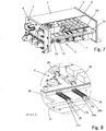
- Figure 7 shows the electronics module in the fully assembled state. Only a small area of the main housing part 4 is shown, so that the view of the heat sink 10 and the power electronics 1, 2 is unobstructed. A part of the heat sink 10 is also cut away so that a partial area of the duct system 20 is exposed.
- FIG 8 the detail A. Fig. 7 , is the area of the duct system 20 in which the double ducts 17 and 18 ( Figure 5 ) branch off from the first channel 21, shown enlarged.
- the cooling fins 26 formed in the respective individual channel 17a-18b can also be seen.
- the partition walls 25 and cooling fins 26 form a compartment for the cooling fluid with a flow guide parallel to the fanning out, which greatly increases the heat exchange surface in the respective channel, but the flow resistance is kept low, since the heat conducting structures 25 and 26 only over the vast majority of their heat exchange surfaces are extended in the longitudinal direction of the channel, that is, parallel to the longitudinal direction of the channel.
- the Figures 9 and 10 illustrate a first iteration step of a computer-aided design of the sewer system 20.
- the layouts 1 and 2 are overlaid by projection into a common image plane.
- a topographical distribution of the power losses of the electronic elements 3a to 3c is determined for the superposition.
- the power electronics 1, 2 of the exemplary embodiment comprise further electronic elements that are shown in FIG Figure 9 recognizable, but not provided with their own reference numerals.
- the electronic elements 3a-3c also represent these further electronic elements.
- the topographical distribution of the power losses, the respective dissipation D is determined column by column for the superimposition of the electronic elements of layouts 1 and 2 arranged in an array.
- a channel is provided for each of the columns of the superimposition of layouts 1 and 2, so that the channel system 20 'of the first iteration has channels in parallel next to one another in a number that corresponds to the number of columns of layouts 1 and 2.
- the cross-sections of the channels are dimensioned as a function of the power dissipation to be dissipated per column. When dimensioning the duct cross-sections, the distances between the next adjacent columns are also taken into account.
- the channel following the column with the greatest power dissipation results in a larger cross-section than for other channels, but due to the close proximity to other channels, the cross-section of the channel is smaller than would correspond to a proportionality with regard to the power dissipation.
- the channel system 20 is optimized with regard to the number of channels, the distances between the channels, the cross section of the respective channel and the arrangement of internal heat conduction structures.
- the optimization can in particular be undertaken with the proviso that the bandwidth of a temperature range in which the electronic elements 3a-3c are cooled by means of the heat sink 10 assumes a minimum or comes close to a minimum. If the electronic elements 3a-3c are cooled by the design of the duct system 20 in such a way that their operating temperatures are close to one another despite differing power losses, the time interval until a first or next failure of one of the electronic elements 3a-3c due to overheating can be maximized.
- the channel system 20 is the result of the optimization.
- the channel system 20 can in particular be designed according to the Hardy Cross method.
- the channel system 20 is advantageously designed in such a way that the cooling fluid can be conveyed through the channel system 20 at such a high flow rate despite small channel cross-sections that the temperature difference between the inlet 13 and the outlet 14 is small in order to achieve a homogeneous operating and cooling state without local hot spots.
- the temperature difference between inlet and outlet is preferably less than 5 ° C, more preferably it is less than 2 ° C.
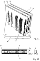
- FIG 11 shows several of the heat sinks 10, which were each generated monolithically and generatively standing next to one another.
- the heat sinks 10 can in particular be generated in parallel, that is to say at the same time, next to one another.
- the heat sinks 10 each consist of a metal material, for example of copper or aluminum, a Cu alloy or Al alloy or a CuAl alloy, which can contain one or more further alloy elements.
- the heat sink 10, or in the example the multiple heat sinks 10, are produced in layers from metal powder selectively by means of an energy beam, preferably by melting.
- an energy beam can also be used as the energy beam, but the cooling body 10 is preferably generated by means of a laser, particularly preferably by means of laser melting.
- the typical layer thickness is 30 to 60 ⁇ m, but the invention is not limited to this.
- the metal powder is applied in layers, expediently in the form of a powder bed. Because of the upright structure, the metal powder in the powder bed layers is solidified in a narrow powder strip corresponding to the cross section of the heat sink. In the powder bed layers, the metal powder is deposited in outer powder strip areas, which in the finished heat sink 10 are the upper surface 11 and the lower surface 12 ( Figure 2 ), each solidified according to the course of the top layer. In the outer areas of the strip, the metal powder is continuously solidified over the length of the respective strip, provided that the respective powder strip does not extend over an optional opening in the cooling body. In any case, the powder strips are solidified in the strip outer regions in such a way that the channel system 20 is tightly closed with respect to the cooling fluid.
- the solidification can be achieved with a single energy beam or simultaneously with several energy beams acting side by side.
- the metal powder is solidified in accordance with the geometry of the channel system 20.
- the result of the additive manufacturing is a heat sink 10 with the inlet 13, the outlet 14 and the inner channel system 20, which is only connected to the environment via the inlet 13 and the outlet 14, but is otherwise tightly encapsulated in the heat sink 10.
- the tightness of the channel system 20 can be significantly increased compared to the prior art Security can be guaranteed. It only needs to be connected to a cooling circuit.
- Figure 11 is designated by 30 a support on which the heat sinks 10 were created standing. Because of the small thickness of the heat sinks 10, support structures 31 are generatively generated at the same time with the heat sinks 10, which support the heat sinks 10 laterally, in particular in each case in the upper area. The support structures 31 are then removed. The heat sinks 10 are separated from the common support 30, for example by means of wire EDM.
- the channel system 20 only has channels which, in a plan view of the upper surface 11, are offset and / or are arranged at an angle to one another. This is not least due to the fact that the layouts 1 and 2 were superimposed during the design of the duct system 20 by projection into a common plane.
- the heat sink 10 can have a channel system which comprises channels that are offset relative to one another in the plan view of the upper surface 11 and / or are at an angle to one another, and channels that are offset from one another in the thickness direction of the heat sink 10 and / or at an angle to each other. In such modifications, the channels of the channel system would not be arranged two-dimensionally, but three-dimensionally.
- a heat sink 10 modified in this way can, for example, have channels in an upper channel level, which primarily serve to cool electronic elements of layout 1, and can furthermore have channels in a lower channel level, which primarily serve to cool electronic elements of layout 2.
- One or more channels of an upper channel level can or can each run in an overlap with one or more channels of a lower channel level, optionally also in a complete overlap one above the other.
- One or more channels of the upper channel level can, instead or in addition, also be extended offset from one or more channels of a lower channel level in the plan view of the upper surface 11.
- a heat sink 10 made of a gradient material is shown schematically.
- the top surface 11 and the bottom surface 12 each consist of pure copper.
- the heat sink 10 consists of pure aluminum. From the core area, the chemical composition of the gradient material in the direction of each of the surfaces 11 and 12 varies quasi continuously, i. H. the heat sink material changes from pure aluminum to CuAl alloys with decreasing Al content and increasing Cu content to pure copper.
- Generative production is particularly suitable for setting such a material gradient in the direction of thickness, the heat sink 10 being expediently produced in a horizontal position for setting a material gradient in the direction of thickness. If the heat sink 10 is generated in a generatively upright position, as is preferred, as in FIG Figure 11 As illustrated, a material gradient can most easily be set in the height direction of the standing heat sink 10.
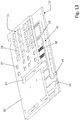
- Figure 13 shows a heat sink 10 in a second embodiment.
- pocket-shaped recesses 28 for the electronic elements 3a and pocket-shaped recesses 29 for the electronic elements 3b are formed in the upper surface 11.
- the recesses 28 are shaped to match the outer surfaces of the electronic elements 3a and the recesses 29 are shaped to be adapted to the outer surfaces of the electronic elements 3b in order to be able to accommodate the associated electronic elements 3a and 3b.
- the relevant electronic elements 3a and 3b are buried in the heat sink 10, preferably arranged upside down.
- the undersides of overhead electronic elements 3a and 3b point away from the upper surface 11, so that electrical contacts of the electronic elements 3a and 3b provided in the area of the underside face away from the heat sink 10.
- Buried electronic elements 3a and 3b protrude with their upper sides facing away from electrical contacts and adjoining side surfaces into the respectively assigned recess 28 or 29.
- the buried electronic elements 3a and 3b are thermally conductive in the area of their upper surfaces with the bottom surface of the assigned recess 28 or 29 and / or on their side surfaces protruding into the recesses 28 and 29 connected to the corresponding side surfaces of the recesses 28 and 29 in a thermally conductive manner.
- the buried arrangement enables heat to be transferred between the heat sink 10 and the respective electronic element 3a and / or 3b over a particularly short transfer path. The heat can be dissipated correspondingly effectively.
- the electronic elements 3a and 3b are located between the heat sink 10 and the circuit board in a buried arrangement.
- the electronic elements 3c of the second layout can also be arranged buried when the heat sink 10 is equipped on both sides. In such designs, recesses that are geometrically adapted to the electronic elements 3c would be provided in the underside surface 12.
- One or more of the recesses in the example the recesses 28 and 29, can as in FIG Figure 13 shown in a plan view of the upper surface 11 in an overlap with channels of the channel system 20.
- one or more recesses for receiving buried electronic elements can be arranged between adjacent channels and overlap with an adjacent channel orthogonally to the plan view of the top surface 11.
- a series of recesses 28 and / or a series of recesses 29, comparable to the recess 27, can be formed as openings and arranged between two adjacent channels of the channel system 20.
- electronic elements protruding into the respective opening would be connected on their side surfaces in a thermally conductive manner to facing side surfaces of the respective opening.
- With the pocket-shaped design of recesses however, a larger-area heat exchange can be achieved.
Landscapes
- Engineering & Computer Science (AREA)
- Microelectronics & Electronic Packaging (AREA)
- Physics & Mathematics (AREA)
- Thermal Sciences (AREA)
- Cooling Or The Like Of Semiconductors Or Solid State Devices (AREA)
- Cooling Or The Like Of Electrical Apparatus (AREA)
Description
- Die Erfindung betrifft ein Elektronikmodul mit einem Kühlkörper und Elektronikelementen, die über eine Oberfläche des Kühlkörpers verteilt angeordnet und zur Kühlung mit der Oberfläche thermisch gekoppelt sind. Bei dem Elektronikmodul kann es sich insbesondere um ein On-Board-Ladegerät, einen DC-DC-Wandler oder ein Motorsteuergerät für ein Fahrzeug, bevorzugt ein Elektro- oder Hybridfahrzeug handeln. Ein bevorzugtes Anwendungsgebiet ist der Automobilbau. Die Erfindung zielt insbesondere auf Elektro- und Hybridautomobile ab.
- Leistungselektroniken erzeugen hohe Verlustleistungen und bedürfen der Kühlung. Die Elektronikkomponenten werden daher auf einem Kühlkörper angeordnet, der von einem Kühlfluid durchströmt wird.
- Bei einem aus der
DE 10 2012 200 325 A1 bekannten Elektronikmodul sind Elektronikkomponenten auf einem Kühlkörper angeordnet, der aus zwei Kühlstrukturen gefügt ist. Eine der Kühlstrukturen bildet einen zu einer Seite offenen Aufnahmeraum. Die andere Kühlstruktur ragt mit Kühlfinnen in den Aufnahmeraum hinein, so dass zwischen den Kühlfinnen im Aufnahmeraum Kühlkanäle gebildet werden. Die beiden Teilstrukturen sind mittels Schraubverbindung zum geschlossenen Kühlkörper gefügt. - Aus der
DE 10 2013 109 589 B3 ist ebenfalls ein Elektronikmodul mit einem aus zwei Kühlstrukturen gefügten Kühlkörper bekannt. Die Kühlstrukturen sind mittels Schweißverbindung gefügt. Kühlfinnen ragen wie beim Kühlkörper derDE 10 2012 200 325 A1 in gleichmäßiger Anordnung von einer der Kühlstrukturen ab und in einen Aufnahmeraum der anderen Kühlstruktur hinein, so dass das Kühlfluid im Aufnahmeraum gleichmäßig über die Wärmeaustauschfläche verteilt wird. - Die
EP 0 838 988 A2 offenbart ein Elektronikmodul mit Elektronikelementen, die zur Kühlung auf einem Kühlkörper angeordnet sind, der eine kastenförmige Kühlstruktur aufweist, die an ihrer von den Elektronikelementen abgewandten Seite von einer Bodenplatte verschlossen wird. Von der Kühlstruktur ragen in hexagonaler Symmetrie angeordnete Zapfen in Richtung auf die Bodenplatte ab. Die Zapfen sind der Anordnung der zu kühlenden Elektronikelemente entsprechend in Zapfengruppen angeordnet. Der durchströmbare Hohlraum wird ferner von einer Zwischenwand in zwei Teilräume unterteilt, die parallel durchströmt werden. Die Zwischenwand ragt ebenfalls von der Kühlstruktur in Richtung auf die Bodenplatte ab. Die Kühlstruktur wird einschließlich Zapfen und Zwischenwand aus einem Metall-Keramik-Kompositmaterial gegossen. - Ein besonders kompaktes Elektronikmodul ist aus der
DE 20 2009 007 008 U1 bekannt. Das Elektronikmodul weist wie die zuvor beschriebenen Elektronikmodule einen aus Unterstrukturen gefügten Kühlkörper auf. Das Elektronikmodul zeichnet sich durch einen innerhalb des Moduls geschlossenen Kühlkreislauf und eine auf dem Modul integrierte lüfterbasierte Wärmeabfuhr aus. - Die
EP 2 801 512 A1 offenbart ein Kühlkörperhybrid, zu dessen Herstellung an einer vorgefertigten Basisstruktur eine Wärmeaustauschstruktur generativ angeformt wird. In einem Ausführungsbeispiel wird an ein Gehäuse einer Leistungselektronik seitlich eine Wärmeaustauschstruktur generativ angeformt. Die Kühlstruktur weist im Inneren gitterförmige oder zelluläre Wärmeaustauschstrukturen in einem sich regelmäßig wiederholenden Muster auf. Es wird auch erwähnt, dass die Kühlstruktur Kühlkanäle aufweisen kann, um ein Kühlsystem mit vorgegebenem Strömungsverlauf zu bilden. - Die
EP 1 484 954 A2 und dieUS 2012/085523 A1 betreffen jeweils einen Kühlkörper, der von einer Kühlflüssigkeit durchflossen werden kann, um beispielsweise mit dem Kühlkörper verbundene Elektronikteile zu kühlen. Der Kühlkörper umfasst mehrere Flüssigkeitskanäle, die nachträglich in den Kühlkörperrohling zum Beispiel durch Bohren eingebracht werden. Bei den Bohrungen handelt es sich um horizontale und vertikale Durchgangsbohrungen, die im Inneren des Kühlkörpers ein verbundenes Kanalnetz bilden. Alle Bohrungsöffnung, bis auf einen Einlass und einen Auslass, werden geschlossen, so dass durch die geschlossenen Öffnungen keine Kühlflüssigkeit austreten kann. - Die
EP 2 709 431 A1 betrifft einen Kühlkörper, der aus einem rahmenförmigen Gehäuse und Einsätzen besteht, die in das Gehäuse eingegeben werden. Die Einsätze umfassen an der in das Gehäuse einzugebenden Seite Kühlrippen. Die Kühlrippen bilden ein Kanalnetz in dem Kühlkörper für eine Kühlflüssigkeit. - Die
EP 2 808 986 A1 betrifft einen Kühlkörper für einen Linearmotor, der im 3D-Druck hergestellt werden kann. - Es ist eine Aufgabe der Erfindung, ein Elektronikmodul mit Elektronikkomponenten und einem durchströmbaren Kühlkörper zu schaffen, wobei das Elektronikmodul kompakt baut, die Elektronikelemente effizient gekühlt werden und die Dichtheit des Kühlkörpers gewährleistet ist.
- Die Erfindung geht von einem Elektronikmodul mit einem durchströmbaren Kühlkörper und Elektronikelementen, die über eine äußere Oberfläche an einer Oberseite des Kühlkörpers verteilt angeordnet sind, aus. Diese äußere Oberfläche wird im Folgenden als oberseitige Oberfläche bezeichnet. Der Kühlkörper weist der oberseitigen Oberfläche abgewandt gegenüberliegend eine äußere unterseitige Oberfläche auf. Die oberseitige Oberfläche und/oder die unterseitige Oberfläche kann oder können jeweils insbesondere eben und parallel sein, was auch einschließt, dass der Kühlkörper an einer oder an beiden äußeren Oberflächen einen treppenartigen Versatz aufweisen kann. Der Kühlkörper ist in bevorzugten Ausführungen plattenförmig und ist besonders bevorzugt eine Kühlplatte im engeren Sinne, d. h. ein Kühlquader mit einer planen oberseitigen Oberfläche, einer planen unterseitigen Oberfläche sowie planen äußeren Seiten. Dies schließt andererseits jedoch nicht aus, dass der Kühlquader eine oder mehrere taschenförmige oder von einer Oberfläche bis zur anderen Oberfläche erstreckte Durchbrüche oder lokale Einschnitte aufweisen kann.
- Die Elektronikelemente sind in einem ersten Layout elektrisch und/oder optisch mittels Leiterbahnen verbunden und zur Kühlung mit der oberseitigen Oberfläche des Kühlkörpers thermisch gekoppelt, jedoch elektrisch vom Kühlkörper isoliert. Weist der Kühlkörper in der oberseitigen Oberfläche eine oder mehrere Ausnehmungen jeweils in Form einer Tasche auf, wird der Boden der jeweiligen Tasche als zur oberseitigen Oberfläche gehörig verstanden. Anstelle oder zusätzlich zu einer oder mehreren taschenförmigen Ausnehmungen kann der Kühlkörper an der oberseitigen Oberfläche auch eine oder mehrere Ausnehmungen jeweils in Form eines Durchbruchs aufweisen. Die optional eine oder optional mehreren Ausnehmungen weist oder weisen jeweils Seitenflächen auf, die von dem umgebenden Bereich der oberseitigen Oberfläche einragen.
- Eines oder mehrere der Elektronikelemente kann oder können jeweils in Bezug auf den Kühlkörper über Kopf angeordnet sein. Das jeweilige, über Kopf angeordnete Elektronikelement weist mit seinen elektrischen Kontakten vom Kühlkörper weg. Soweit eines oder mehrere Elektronikelemente über Kopf angeordnet ist oder sind, kann das betreffende Elektronikelement an seiner von den elektrischen Kontakten abgewandte Oberseite direkt mit der oberseitigen Oberfläche des Kühlkörpers thermisch leitend verbunden sein. Weist der Kühlkörper eine oder mehrere Ausnehmungen auf, kann das jeweilige, über Kopf angeordnete Elektronikelement vorteilhafterweise in die Ausnehmung ragen, d.h. in den Kühlkörper vergraben sein. Ragt das jeweilige vergrabene Elektronikelement in eine taschenförmige Ausnehmung, kann es an seiner Oberseite und/oder an einer oder mehreren seiner Seitenflächen thermisch leitend mit dem Boden und/oder einer oder mehreren Seitenflächen der Ausnehmung verbunden sein. Ragt das jeweilige vergrabene Elektronikelement in eine als Durchbruch geformte Ausnehmung des Kühlkörpers, kann es an einer oder mehreren seiner Seitenflächen mit einer oder mehreren Seitenflächen der betreffenden Ausnehmung thermisch leitend verbunden sein.
- Die Elektronikelemente können auf einer Leiterplatine angeordnet und diese Leiterplatine kann thermisch leitend mit der oberseitigen Oberfläche des Kühlkörpers verbunden sein. Alternativ können die Elektronikelemente auch direkt auf der oberseitigen Oberfläche angeordnet und wärmeleitend mit der Oberfläche verbunden sein. Es sind auch Ausführungen möglich, in denen eines oder mehrere der Elektronikelemente auf einer Leiterplatine angeordnet und eines oder mehrere andere der Elektronikelemente direkt auf der oberseitigen Oberfläche des Kühlkörpers angeordnet sind. Die thermische Kopplung kann beispielsweise mittels eines Wärmeleitpads verwirklicht sein. Das Wärmeleitpad kann zur Befestigung an der Platine und/oder direkt an Elektronikelementen und zur Befestigung am Kühlkörper beidseits adhäsiv beschichtet sein. Anstelle oder zusätzlich zu einer adhäsiven Beschichtung kann zur Befestigung aber auch ein wärmeleitender Klebstoff aufgetragen werden.
- Der Kühlkörper weist einen Einlass für ein Kühlfluid, einen Auslass für das Kühlfluid und ein den Kühlkörper durchziehendes Kanalsystem mit im Inneren des Kühlkörpers verzweigten Kanälen auf. Das Kanalsystem verbindet den Einlass mit dem Auslass.
- Nach der Erfindung ist der Kühlkörper ein generativ erzeugter Monolith, d. h. eine im Ganzen in einem Stück generativ erzeugte Einheit. Aufgrund der monolithisch generativen Erzeugung kann das Kanalsystem der topografischen Verteilung der Verlustleistungen und somit der Wärmeerzeugung der Elektronikelemente genauer angepasst werden, als dies bislang, etwa bei einem gegossenen Kühlkörper, möglich ist. Aufgrund der generativ monolithischen Erzeugung ist auch die Abdichtung des Kühlkörpers kein Problem mehr, da der Kühlkörper von vornherein abgesehen von Einlass und Auslass, optional auch einem oder mehreren weiteren Einlässen und/oder Auslässen, als eine in Bezug auf ihre äußeren Oberflächen geschlossene Struktur hergestellt wird. Es entfallen Fertigungsschritte, da keine Kühlkörperteile separat voneinander gefertigt und anschließend gefügt werden müssen. Geometriefehler des Kanalsystems, wie sie bei separater Fertigung und anschließendem Fügen auftreten können, werden ausgeschlossen.
- Die Querschnitte der Kanäle können flexibel variiert werden, zum einen von Kanal zu Kanal, zum anderen aber auch über den Verlauf des jeweils gleichen Kanals. In den Kanälen können sehr feine Wärmeleitstrukturen erzeugt werden, in Form von Kühlpins, Kühlfinnen oder auch in Längsrichtung des jeweiligen Kanals langgestreckten Kühlrippen. Die innere Oberfläche ist bei einem, mehreren oder bei sämtlichen Kanälen durch eine bei der generativen Erzeugung geschaffene Strukturierung gegenüber glatten Oberflächen deutlich vergrößert, um den Wärmeübergang pro Flächeneinheit der oberseitigen Oberfläche zu vergrößern und/oder dem Wärmebedarf entsprechend in bestimmten Flächenbereichen zu konzentrieren bzw. zu erhöhen.
- Der erfindungsgemäß generativ als Monolith erzeugte Kühlkörper kann im Ergebnis bei gleicher Kühlleistung in kleineren äußeren Abmessungen als ein in herkömmlicher Weise geformter und gefügter Kühlkörper bereitgestellt werden. Der Kühlkörper kann insbesondere in einer geringen Dicke ausgeführt sein, wobei die Dicke parallel zur Draufsicht auf die oberseitige Oberfläche gemessen wird.
- Die Erfindung betrifft auch ein Verfahren zur Herstellung eines Kühlkörpers für ein Elektronikmodul, wobei der Kühlkörper einen Einlass für ein Kühlfluid, einen Auslass für das Kühlfluid, ein den Kühlkörper durchziehendes Kanalsystem, eine für das Kühlfluid dichte Deckschicht mit einer äußeren oberseitigen Oberfläche und eine für das Kühlfluid dichte weitere Deckschicht mit einer äußeren unterseitigen Oberfläche. Die oberseitige und/oder die unterseitige Oberfläche kann oder können jeweils plane, zumindest im Wesentlichen glatte Oberflächen sein. Die oberseitige Oberfläche und/oder die unterseitige Oberfläche kann oder können eine oder mehrere Ausnehmungen aufweisen. Die jeweilige Ausnehmung kann als eine in die oberseitige Oberfläche oder die unterseitige Oberfläche eingelassene Tasche oder als ein von der oberseitigen Oberfläche bis zur unterseitigen Oberfläche erstreckter Durchbruch geformt sein. Der Kühlkörper kann insbesondere wie vorstehend beschrieben ausgeführt sein.
- Im erfindungsgemäßen Verfahren wird der Kühlkörper im Ganzen generativ durch Auftragen von Metallpulver in Pulverbettschichten und Verfestigen des Metallpulvers der jeweiligen Pulverbettschicht erzeugt. Das Metallpulver wird in der jeweiligen Pulverbettschicht der Geometrie des Kanalsystems, des Einlasses und des Auslasses entsprechend selektiv mittels Energiestrahl, vorzugsweise Laser, verfestigt. Das Metallpulver kann mittels des Energiestrahls zum Verfestigen insbesondere geschmolzen werden. In um das Kanalsystem erstreckten Außenbereichen wird das Metallpulver der jeweiligen Pulverbettschicht der Geometrie der Deckschichten entsprechend selektiv mittels Energiestrahl, vorzugsweise Laser, verfestigt, um das Kanalsystem zwischen den Deckschichten dicht einzuschließen.
- Zur Verfestigung des Metallpulvers der jeweiligen Pulverbettschicht wird in ersten Ausführungen des Verfahrens nur ein einziger Energiestrahl, vorzugsweise Laser, eingesetzt. In modifizierten Verfahren können pro Pulverbettschicht oder auch nur in ausgewählten Pulverbettschichten mehrere Energiestrahlen, vorzugsweise Laser, gleichzeitig, also parallel in unterschiedlichen Pulverbettbereichen wirkend, verwendet werden.
- In einem ersten Verfahren wird der Kühlkörper liegend erzeugt, indem eine oder mehrere Pulverbettschichten nacheinander jeweils einer der Deckschichten entsprechend ganzflächig mittels Energiestrahl verfestigt wird oder werden, um die eine der Deckschichten zu erhalten. Nach Erzeugung der betreffenden Deckschicht wird das Metallpulver in nachfolgend sukzessive aufgetragenen Pulverbettschichten der Geometrie des Kanalsystems entsprechend selektiv mittels Energiestrahl verfestigt. Anschließend werden die zunächst noch offenen Kanäle über mehrere nacheinander aufgetragene und jeweils selektiv verfestigte Pulverbettschichten geschlossen. In der letzten Phase der generativen Erzeugung wird eine oder werden mehrere dann noch aufgetragene Pulverschichten der anderen Deckschicht entsprechend jeweils ganzflächig verfestigt, um die andere Deckschicht zu erhalten. Der Schichtkörper wird im ersten Verfahren somit von einer Deckschicht aus gesehen in Richtung auf die andere aufgebaut. Der Schichtaufbau erfolgt in Dickenrichtung des Kühlkörpers.
- In einem bevorzugten zweiten Verfahren wird der Kühlkörper stehend aufgebaut, indem die beiden genannten Deckschichten sukzessive, Pulverbettschicht für Pulverbettschicht, erzeugt werden. Im zweiten Verfahren wird das Metallpulver in den Pulverbettschichten jeweils in einem dem Querschnitt des Kühlkörpers entsprechenden Pulverstreifen selektiv verfestigt. Das Metallpulver wird zum Erhalt der Deckschichten in den Pulverstreifen jeweils in äußeren Pulverstreifenbereichen der jeweiligen Deckschicht entsprechend und im zwischen den äußeren Pulverstreifenbereichen liegenden zentralen Pulverstreifenbereich der Geometrie des Kanalsystems entsprechend mittels Energiestrahl selektiv verfestigt. Im zweiten Verfahren wird der Kühlkörper Schicht für Schicht sukzessive in eine Flächenrichtung der oberseitigen Oberfläche, d. h. von einer Seitenwand des Kühlkörpers in Richtung auf eine gegenüberliegende Seitenwand aufgebaut.
- Der Kühlkörper kann insbesondere aus Kupfer und/oder Aluminium und/oder einer Legierung bestehen, die Kupfer und/oder Aluminium als wesentliche Bestandteile enthält. Der Kühlkörper kann dementsprechend insbesondere ein Kühlkörper nur aus Kupfer oder nur aus Aluminium, aus einer Kupferlegierung, einer Aluminiumlegierung oder einer CuAl-Basislegierung bestehen.
- Der generativ erzeugte Werkstoff des Kühlkörpers kann über den gesamten Kühlkörper der chemischen Zusammensetzung nach homogen sein. In Modifikationen kann der generativ erzeugte Werkstoff aber auch ein Gradientenwerkstoff sein. Bei einem aus einem Gradientenwerkstoff bestehenden Kühlkörper kann die chemische Zusammensetzung des Werkstoffs in Draufsicht auf die oberseitige Oberfläche gesehen in eine Längenrichtung und/oder eine Breitenrichtung des Kühlkörpers variieren. Bevorzugter variiert die Werkstoffzusammensetzung parallel zur Draufsicht in Dickenrichtung des Kühlkörpers. Ein Werkstoffgradient kann insbesondere in Richtung des generativen Schichtaufbaus eingestellt werden, indem die chemische Zusammensetzung des Metallpulvers von einer Pulverbettschicht zu einer nächsten verändert wird. Die Zusammensetzung des Metallpulvers kann sukzessive über mehrere Pulverbettschichten verändert werden, grundsätzlich ist aber auch vorstellbar, die Zusammensetzung in einem größeren Sprung nur einmal oder in wenigen Schritten zu ändern. Wird der Kühlkörper wie bevorzugt stehend erzeugt, kann ein Werkstoffgradient ohne weiteres in Fortschrittsrichtung des Schichtaufbaus, von einem Ende der oberseitigen Oberfläche in Richtung auf ein gegenüberliegendes Ende der oberseitigen Oberfläche, variiert werden. Für die Einstellung eines Werkstoffgradienten bevorzugt in Dickenrichtung, also von der oberseitigen Oberfläche in Richtung auf die unterseitige Oberfläche oder in die umgekehrte Richtung, eignet sich eher ein in Dickenrichtung fortschreitender Schichtaufbau, also die Erzeugung des Kühlkörpers liegend dem ersten Verfahren entsprechend.
- Vorteilhafte Ausgestaltungen werden auch in den Unteransprüchen und in den Kombinationen der Unteransprüche offenbart.
- Nachfolgend werden Ausführungsbeispiele der Erfindung anhand von Figuren erläutert. An den Ausführungsbeispieln offenbar werdende Merkmale bilden jeweils einzeln und in jeder Merkmalskombination die Gegenstände der Ansprüche, die vorstehend erläuterten Ausgestaltungen und auch die Aspekte vorteilhaft weiter. Es zeigen:
- Figur 1
- ein Elektronikmodul mit einem Kühlkörper eines ersten Ausführungsbeispiels, der sandwichartig zwischen zwei mit Elektronikelementen bestückten Platinen angeordnet und mit den Elektronikelementen thermisch gekoppelt ist,
- Figur 2
- Komponenten des Elektronikmoduls in einer Explosionsdarstellung,
- Figur 3
- eine Draufsicht auf eine der Platinen,
- Figur 4
- einen Querschnitt des Kühlkörpers,
- Figur 5
- den Kühlkörper in einem zur Draufsicht der
Figur 3 parallelen Schnitt, - Figur 6
- das Detail E der
Figur 4 , - Figur 7
- eine isometrische Sicht in ein geöffnetes Gehäuse des Elektronikmoduls mit aufgeschnittenem Kühlkörper,
- Figur 8
- das Detail A der
Figur 7 , - Figur 9
- überlagerte Layouts von Elektronikelementen mit einer topografischen Verteilung von Verlustleistungen der Elektronikelemente,
- Figur 10
- ein der topografischen Verteilung der Verlustleistungen angepasstes Kanalsystem des Kühlkörpers in einer ersten Iteration,
- Figur 11
- generativ stehend erzeugte Kühlkörper,
- Figur 12
- einen Kühlkörper aus einem Gradientenwerkstoff, und
- Figur 13
- einen Kühlkörper eines zweiten Ausführungsbeispiels.
-
Figur 1 zeigt ein Elektronikmodul unmittelbar vor dem Zusammenbau. Das Elektronikmodul umfasst einen Kühlkörper 10, der sandwichartig zwischen Elektronikelementen 3a und 3b eines ersten Layouts 1 und Elektronikelementen 3c eines zweiten Layouts 2 angeordnet ist, um die Elektronikelemente des jeweiligen Layouts 1 und 2 im Betrieb des Elektronikmoduls zu kühlen. Die Kühlung erfolgt aktiv, indem ein Kühlfluid, vorzugsweise eine Kühlflüssigkeit, durch ein den Kühlkörper 10 im Inneren durchziehendes Kanalsystem gefördert wird. Im Betrieb strömt das Kühlfluid durch einen Einlass 13 des Kühlkörpers 10 in den Kühlkörper 10, durchströmt das innere Kanalsystem und wird durch einen Auslass 14 wieder aus dem Kühlkörper 10 geführt. - Im fertiggestellten Zustand ist der Kühlkörper 10 mit den Elektronikelementen 3a-3c in einem Gehäuse des Elektronikmoduls geschützt aufgenommen. Das Gehäuse kann staub- und wasserdicht und insbesondere so ausgebildet sein, dass es die Anforderungen an ein Gehäuse einer Leistungselektronik im Motorraum eines Elektro-Hybrid- oder reinen Elektrofahrzeugs erfüllt, beispielsweise der Schutzart IP6K6 oder IP6K6K oder IP6K9K entspricht. Das Gehäuse ist aus mehreren separat gefertigten Gehäuseteilen gefügt. Es umfasst ein Gehäusehauptteil 4, das im zusammengebauten Zustand den Kühlkörper 10 mit den Elektronikelementen 3a-3c umgibt, und eine Rückwand 5, die das Gehäusehauptteil 4 an einer Rückseite dicht verschließt. An der Frontseite wird das Gehäusehauptteil 4 im zusammengebauten Zustand von einer Frontwand 6 verschlossen. Die Kühlplatte 10 kann mit der Frontwand 6 fest gefügt sein, so dass im gleichen Montageschritt der Kühlkörper 10 mit den Elektronikelementen 3a-3c in das Gehäusehauptteil 4 eingeschoben und dabei die Frontwand 6 gegen das Gehäusehauptteil 4 geschoben werden kann. Die Frontwand 6 wird im nächsten Schritt mit dem Gehäusehauptteil 4 fest verbunden.
- Um den Kühlkörper 10 beim Einschieben zu führen, sind im Bereich des Gehäusehauptteils 4 Führungsstrukturen vorgesehen. Im Ausführungsbeispiel sind Führungsstrukturen zur Führung des Kühlkörpers 10 nur im Frontbereich des Gehäusehauptteils 4 vorgesehen.
- Wie in
Figur 2 zu erkennen, können die Führungsstrukturen zur Führung der Einschiebeeinheit 6, 10 an einer separat vom Gehäusehauptteil 4 gefertigten, rahmenförmigen Adapterstruktur 7 geformt sein. Die Adapterstruktur 7 ist wie auch die Rückwand 5 mit dem entsprechend vereinfachten Gehäusehauptteil 4 fest gefügt. Die Rückwand 6 und/oder die Adapterstruktur 7 kann oder können jeweils umlaufend stoffschlüssig und dadurch staub- und/oder wasserdicht mit dem Gehäusehauptteil 4 gefügt sein, insbesondere mittels Schweißverbindung, Lötverbindung, oder Klebeverbindung. Die Frontwand 6 wird mit dem Gehäusehauptteil 4 vorzugsweise mittels Schraubverbindung oder Metallklammern verbunden, wobei die Adapterstruktur 7 für das Gehäusehauptteil 4 die zur Herstellung solch einer Verbindung erforderlichen Fügeelemente, bevorzugt Schraubelemente wie insbesondere Schaublöcher, bereitstellt. Die Dichtheit wird durch eine Gehäusedichtung 8 gewährleistet, die im gefügten Zustand zwischen der Adapterstruktur 7 und der Frontwand 6 angeordnet ist. - Das Gehäusehauptteil 4 kann aus einem einfachen Blechzuschnitt durch Kanten und anschließendes Schweißen, Löten oder Kleben kostengünstig in Serie gefertigt werden, falls die Führungsstrukturen zur Führung des Kühlkörpers 10 und/oder die Befestigungselemente zur Befestigung der Frontwand 6 durch eine separat gefertigte Adapterstruktur 7 bereitgestellt werden. Ein Gehäusehauptteil 4 mit integrierten Führungsstrukturen kann beispielsweise durch Strangpressen gefertigt werden. Die optionale Adapterstruktur 7, die bei der Montage dem Positionieren und Führen des Kühlkörpers 10 dient, ist vorzugsweise ein Gussteil, kann aber beispielsweise auch mittels Zerspanen gefertigt werden. Die Rückwand 5 erfüllt vorzugsweise nicht nur die Funktion eines rückseitigen Verschlusses des Gehäuses 4-7, sondern zusätzlich auch noch eine Funktion beim Positionieren und Halten der Kühlplatte 10. Für diese Zweitfunktion kann an der Innenseite der Rückwand 5 eine Positionierstruktur 5a für den Kühlkörper 10 geformt sein, beispielsweise eine Nut oder ein vorstehendes Rippenpaar, in die oder zwischen die der Kühlkörper 10 bei der Montage eingeschoben wird. Die Frontwand 6 kann insbesondere ein gelasertes oder gestanztes Blech, zerspantes Vollmaterial oder ein Gussteil sein. Das gefügte Gehäuse 4-7 ist wie erläutert bevorzugt als Metallgehäuse ausgeführt. Grundsätzlich kann es stattdessen aber auch als Kunststoffgehäuse oder als ein aus Metallteilen und Kunststoffteilen gefügtes Gehäuse ausgeführt sein.
- An der Frontwand 6 sind Anschlüsse 9 angeordnet, über die elektrische Energie sowie elektrische und/oder optische Signale zwischen der auf dem Kühlkörper 10 angeordneten Leistungselektronik 3a-3c und einem oder mehreren angeschlossenen Geräten übertragen werden können.
- Die Elektronikelemente 3a und 3b des ersten Layouts 1 sind an einer äußeren Oberfläche 11 an einer Oberseite des Kühlkörpers 10 angeordnet. Die Elektronikelemente 3c des zweiten Layouts 2 sind an einer äußeren Oberfläche 12 an einer Unterseite des Kühlkörpers 10 angeordnet. Mit den Begriffen "Oberseite" und "Unterseite" soll lediglich zum Ausdruck gebracht werden, dass der Kühlkörper 10 zwischen dem ersten Layout 1 von Elektronikelementen 3a und 3b und dem zweiten Layout 2 von Elektronikelementen 3c angeordnet ist. Die Begriffe "Oberseite" und "Unterseite" legen die Orientierung des Kühlkörpers 10 im Raum nicht fest.
- Der Kühlkörper 10 ist als dünne Kühlplatte und wie bevorzugt zumindest im Wesentlichen als flacher Kühlquader geformt. Der Kühlkörper 10 weist dementsprechend eine Dicke auf, die wesentlich geringer als eine in Draufsicht auf die Oberseite gemessene Länge und Breite ist. Die Länge und die Breite können jeweils mehr als zehnmal so groß wie die Dicke sein. Bevorzugt sind die Länge und die Breite jeweils zwanzigmal so groß wie die Dicke.
- Die Elektronikelemente des ersten Layouts 1 sind auf einer Platine angeordnet, die mittels eines Wärmeleitpads 1a wärmeleitend mit der oberseitigen Oberfläche 11 verbunden. Die Elektronikelemente des zweiten Layouts sind ebenfalls auf einer Platine angeordnet und über ein Wärmeleitpad 2a wärmeleitend mit der unterseitigen Oberfläche 12 verbunden. Anstelle jeweils eines Wärmeleitpads 1a und 2a oder einer Wärmeleitfolie oder dergleichen können die Platinen mit den Elektronikelementen 3a bis 3c auch auf andere Weise an der jeweiligen Oberfläche 11 oder 12 befestigt und gut wärmeleitend mit dem Kühlkörper 10 verbunden sein. Gleichwohl sind sie trotz guter thermischen Kopplung vom metallenen Kühlkörper 10 elektrisch isoliert. Andererseits ist auch eine lokale direkte Entwärmung von Spulen über dünn folierte Kupferbleche als partielles Wärmeleitpad zum Kühlkörper 10 hin möglich.
- Mit 10a sind in
Figur 2 Anschlüsse für die Fluidzufuhr und -abfuhr bezeichnet, ein Anschluss 10a für den Einlass 13 und der andere für den Auslass 14 des Kühlkörper 10 (Figur 1 ). Der Einlass 13 und der Auslass 14 sind in einer Seitenwand des Kühlkörpers 10 zwischen den Oberflächen 11 und 12 gebildet. Das Gehäusehauptteil 4 weist mit dem Einlass 13 und dem Auslass 14 überlappende Durchgänge auf, durch die die Anschlüsse 10a mit dem Einlass 13 und dem Auslass 14 verbunden und die im montierten Zustand mittels der Anschlüsse 10a abgedichtet werden. - Um die äußeren Abmessungen des Kühlkörpers 10, insbesondere die Abmessungen in Dickenrichtung, bei gegebener Verlustleistung der Elektronikkomponenten 3a-3c gegenüber bekannten Kühlstrukturen zu reduzieren, wird der Kühlkörper 10 generativ monolithisch, d. h. im Ganzen in einem einzigen Stück, erzeugt. Mit der monolithisch generativen Erzeugung eröffnen sich in Bezug auf die Gestaltung eines den Kühlkörper 10 durchziehenden Kanalsystems Möglichkeiten der Optimierung, die konventionelle Fertigungsverfahren nicht bieten. Innerhalb von Kühlkanälen des Kanalsystems können Wärmeleitstrukturen in geringerer Dicke und dadurch größerer Zahl und Oberfläche geschaffen und somit ein intensiverer Wärmeübergang vom Kühlfluid auf den Kühlkörper 10 erhalten werden. In den nachfolgenden Figuren wird ein optimiertes Kanalsystem für eine gerichtete Kühlung der Elektronikelemente 3a-3c anhand eines Beispiels illustriert.
-
Figur 3 zeigt das Elektronikmodul in einem Schnitt durch das Gehäuse 4-7 und in Draufsicht auf die Elektronikmodule 3a und 3b des ersten Layouts 1 und die oberseitige Oberfläche Streifenabschnitte des unter dem Layout 1 befindlichen Kühlkörpers 10. -
Figur 4 zeigt das Elektronikmodul in dem inFigur 3 eingetragenen Schnitt B-B, der insbesondere einen Querschnitt des Kühlkörpers 10 enthält. -
Figur 5 zeigt den Kühlkörper 10 in einer zentralen Schnittebene C-C, die inFigur 4 eingetragen ist. Erkennbar ist insbesondere das den Kühlkörper 10 im Innere durchziehende Kanalsystem 20. Das Kanalsystem 20 umfasst einen mit dem Einlass 13 verbundenen ersten Kanal 21 und mehrere stromabwärts des Einlasses 13 vom ersten Kanal 21 abzweigende Kanäle 15-19. Die Kanäle 15-19 erstrecken sich vom ersten Kanal 21 separat voneinander bis in einen mit dem Auslass 14 verbundenen Sammelkanal 23. Der erste Kanal 21 und der Sammelkanal 23 sind Kanalabschnitte eines in einer Schleife durch den Kühlkörper 10 geführten Hauptkanals. Vom ersten Kanal 21 zweigen in Strömungsrichtung fortschreitend ein zweiter Kanal 15, ein dritter Kanal 16, ein vierter Kanal 17, ein fünfter Kanal 18 und ein sechster Kanal 19 ab. Die abzweigenden Kanäle 15-19 sind jeweils gerade und parallel zueinander angeordnet. Die Abstände, die sie in der Draufsicht auf die Schnittebene C-C voneinander aufweisen, können unterschiedlich sein. So ist beispielsweise der Abstand zwischen den Kanälen 15 und 16 kleiner als der Abstand zwischen den Kanälen 16 und 17, und die Kanäle 17 und 18 weisen innerhalb der Gruppe der abzweigenden Kanäle 15-19 den geringsten Abstand voneinander auf. - Der Einlass 13 ist nahe bei dem Auslass 14 an einer Seitenwand des Kühlkörpers 10 gebildet.
- Der Hauptkanal erstreckt sich vom Einlass 13 bis zum Auslass 14 in einer Schleife durch den Kühlkörper 10. Der Hauptkanal erstreckt sich nahe bei und beispielhaft parallel zu den Seitenwänden des Kühlkörpers 10. Der Hauptkanal bildet eine äußere Umfangsschleife des Kanalsystems 20. Er weist in Strömungsrichtung gezählt den ersten Kanal 21 als einen ersten Schleifenabschnitt, daran anschließend einen Kanal 22 als zweiten Schleifenabschnitt, an den Kanal 22 als dritten Schleifenabschnitt anschließend den Sammelkanal 23 und an diesen anschließend als vierten Schleifenabschnitt einen Auslasskanal 24 auf. Der erste Kanal 21 und der Sammelkanal 23 verlaufen parallel zueinander. Die Kanäle 22 und 24 verlaufen parallel zueinander und auch parallel zu den abzweigenden Kanälen 15-19.
- Der erste Kanal 21 dient als Verteilerkanal. Im Sammelkanal 23 wird das längs des ersten Kanals 21 auf die Kanäle 15-19 verteilte Kühlfluid zusammengeführt und in kontinuierlich an den Sammelkanal 23 sich anschließenden Auslasskanal 24 zum Auslass 14 und über den Auslass 14 abgeführt. Der Kanal 22 verbindet den ersten Kanal 21 mit dem Sammelkanal 23. Die Kanäle 22 und 24 können wie die abzweigenden Kanälen 15-19 insbesondere unterhalb von Elektronikelementen des ersten Layouts 1 und/oder Elektronikelementen des zweiten Layouts 2 verlaufen. Bevorzugt erstrecken sie sich zumindest in Überlappung mit den zu kühlenden Elektronikelementen 3a-3c. Zweckmäßigerweise erstrecken sich auch der erste Kanal 21 und der Sammelkanal 23 in Überlappung mit zu kühlenden Elektronikelementen des ersten Layouts 1 und/oder des zweiten Layouts 2.
- Die Querschnitte der Kanäle 15-19 und 21-24 und auch die in der Draufsicht bzw. Schnittebene C-C gemessenen Abstände zwischen nächstbenachbarten Kanälen 15-19, 22 und 24 sind der Funktion des jeweiligen Kanals angepasst. Die abzweigenden Kanäle 15 bis 19 und der Verbindungskanal 24 sind in Bezug auf ihre Abstände und Strömungsquerschnitte an die topografische Verteilung der Verlustleistungen der Elektronikelemente 3a-3c angepasst. Grundsätzlich gilt dies auch für den Kanal 24, der allerdings über die Funktion nur des Kühlens hinaus auch seiner Abführfunktion wegen einen größeren Querschnitt als die Kanäle 15 bis 19 und 22 hat. Das Gleiche gilt für den ersten Kanal 21, der neben einer Kühlfunktion insbesondere die Verteilfunktion erfüllt, und den Sammelkanal 23, der neben einer Kühlfunktion die Sammelfunktion erfüllt.
- In Flächenbereichen, in denen keine Elektronikelemente angeordnet oder die Verlustleistungen der im jeweiligen Flächenbereich angeordneten Elektronikelemente 3a-3c nur gering sind, kann der Kühlkörper 10 Ausnehmungen 27 aufweisen. Eine oder mehrere Ausnehmungen 27 können taschenförmige Vertiefungen oder Aussparungen oder, wie im Ausführungsbeispiel, Durchbrüche sein. Das Gewicht des Kühlkörpers 10 kann dem Volumen der jeweiligen Ausnehmung 27 entsprechend gegenüber einem überall vollen Kühlkörper 10 reduziert werden. Eine Gewichtsreduzierung ist in vielen Anwendungen, insbesondere im Automobilbau, von Vorteil. Nicht zuletzt der generativen Fertigung wegen kann eine Ausnehmung 27, wie im Beispiel, oder können mehrere Ausnehmungen zwischen benachbarten Kanälen des Kanalsystems 20 vorgesehen sein, wobei eine oder mehrere dieser zwischen benachbarten Kanälen platzierten Ausnehmungen in einer zur Draufsicht auf die oberseitige Oberfläche 11 orthogonalen Projektion mit den nächstbenachbarten Kanälen überlappen, vorzugsweise jeweils als ein Durchgang gebildet sein können.
- Die generative Fertigung hat nicht nur den Vorteil, dass einer oder mehrere Kanäle des Kanalsystems 20 mit kleinem Kanalquerschnitt und/oder einem schlitzförmigen Querschnitt erzeugt werden kann. Innerhalb eines oder mehrerer der Kanäle 15-19 und 21-24, insbesondere in den abzweigenden Kanälen 15-19 und dem Verbindungskanal 22, können vorteilhafterweise schmale Wärmeleitstrukturen erzeugt und dadurch die mit dem Kühlfluid in Kontakt stehende Wärmeaustauschfläche des jeweiligen Kanals deutlich vergrößert werden. Nächstbenachbarte Kanäle können beispielsweise durch extrem dünne Trennwände voneinander getrennt sein. So sind beispielhaft die Kanäle 17, 18, 19 und 22 jeweils als Doppelkanäle ausgebildet, indem sie über wenigstens den überwiegenden Teil der jeweiligen Kanallänge, im Ausführungsbeispiel über die jeweils gesamte Kanallänge, mittels einer dünnen Trennwand 25 voneinander separiert sind. Die Einzelkanäle können beim jeweiligen Doppelkanal 17, 18, 19 und/oder 22 den gleichen Kanalquerschnitt aufweisen, was die rechnerische Auslegung des Kanalsystems 20 erleichtert. Grundsätzlich können sich aber auch die Einzelkanäle des jeweiligen Doppelkanals dem Kanalquerschnitt nach voneinander unterscheiden. Das Kanalsystem 20 kann einen oder mehrere Dreifach- und/oder Vierfach-Kanäle und grundsätzlich eine beliebige Anzahl von unmittelbar nebeneinander angeordneten und durch jeweils eine dünne Trennwand 25 voneinander separierten Kanälen in der Art der Doppelkanäle 17, 18, 19 und 22 aufweisen. Die abzweigenden Kanäle 15-19 müssen nicht geradlinig verlaufen, obgleich ein gerader Verlauf bevorzugt wird, sondern können auch Formen wie Kurven, Schleifen oder abgewinkelte Bahnen annehmen.
- In den Kanälen 17 und 18 sind ferner über die jeweilige Kanallänge gesehen lokal nur erstreckte Kühlfinnen 26 angeordnet. Derartig lokalisierte Wärmeleitstrukturen sind zweckmäßigerweise unterhalb von Elektronikelementen geformt, die eine im Vergleich zu anderen Elektronikelementen höhere Verlustleistung erzeugen.
- Wie die Zusammenschau der
Figuren 3 bis 5 zeigt, sind die eine in Breitenrichtung des Kühlkörpers 10 erstreckten Kanäle 15-19, 22 und 24 jeweils in Überlappung mit Elektronikelementen 3a und 3b des ersten Layouts 1 und/oder Elektronikelementen 3c des zweiten Layouts 2 angeordnet, um die Verlustleistung auf kurzem Weg vom jeweiligen Elektronikelement in das Kühlfluid zu übertragen und mittels des Kanalsystems 20 aus dem Kühlkörper 10 abzuführen. Die Elektronikelemente 3a-3c sind dem jeweiligen Layout 1 oder 2 entsprechend in Arrays angeordnet. Der Verlauf der Kanäle des Kanalsystems 20 ist der jeweiligen Array-Anordnung angepasst, indem sich der erste Kanal 21 und der Sammelkanal 23 unter äußeren Zeilen von Elektronikelementen 3a-3c und die Kanäle 15-19, 22 und 24 unter Spalten von Elektronikelementen 3a-3c erstrecken. - Im Querschnitt der
Figur 4 ist der den Spalten der beiden Layouts 1 und 2 folgende Verlauf von Kanälen erkennbar. -
Figur 6 zeigt das Detail E derFigur 4 , nämlich den Bereich um die beiden Doppelkanäle 17 und 18, die mittels jeweils einer dünnen Trennwand 25 gebildet sind. Die den Doppelkanal 17 bildenden Einzelkanäle sind mit 17a und 17b und die den Doppelkanal 18 bildenden Einzelkanäle sind mit 18a und 18b bezeichnet. Im Querschnitt derFigur 6 sind ferner dünne Kühlfinnen 26 erkennbar, die in jedem der Einzelkanäle 17a-18b geformt sind. Die Kühlfinnen 26 ragen von einer inneren Kanaloberfläche in den Querschnitt des jeweiligen Kanals 17a-18b hinein und vergrößern im jeweiligen Kanalquerschnitt dessen Wärmeaustauschfläche. - Die Trennwände 25 und/oder die Kühlfinnen 26 und/oder anders geformte, in den jeweiligen Kanal hinein ragende Wärmeleitstrukturen können aufgrund der generativen Erzeugung des Kühlkörpers 10 sehr filigran sein. So können Wärmeleitstrukturen, wie etwa die Strukturen 25 und 26, vorteilhafterweise über eine Länge von 1 cm und mehr in einer Dicke von weniger als 1 mm ausgeführt sein. In bevorzugten Ausführungen sind die Wärmeleitstrukturen 25 und 26 höchstens 0.5 mm dick.
- In der nachstehenden Tabelle sind bevorzugte Abmessungen eines Kühlkörpers 10 in Form bevorzugter Bereiche zusammengefasst. In Klammern werden ferner besonders bevorzugte Bereiche angegeben. Der jeweilige Kühlkörper 10 kann sämtlichen Längenmaßbereichen der Tabelle entsprechen. Alternativ kann beim jeweiligen Kühlkörper 10 aber auch jede Unterkombination nur verwirklicht sein.
Längenmaß bevorzugte Bereiche Länge 100-500 mm (100-300 mm) Breite 100-500 mm (100-300 mm) Dicke 3-20 mm (3-10 mm) Kanalquerschnitt Querschnittsbreite 2-15 mm (2-10 mm) Querschnittshöhe 1-15 mm (1-8 mm) Dicke von Trennwänden 25 0,2-1 mm (0,2-0,5 mm) Dicke von inneren Wärmeleitstrukturen, beispielsweise Kühlfinns 26 0,2-1_mm (0,2-0,5 mm) -
Figur 7 zeigt das Elektronikmodul im fertig montierten Zustand. Vom Gehäusehauptteil 4 ist nur ein kleiner Bereich dargestellt, so dass der Blick auf den Kühlkörper 10 und die Leistungselektronik 1, 2 frei ist. Vom Kühlkörper 10 ist ebenfalls ein Teil weggeschnitten, so dass ein Teilbereich des Kanalsystems 20 freiliegt. - In
Figur 8 , dem Detail A ausFig. 7 , ist der Bereich des Kanalsystems 20, in dem die Doppelkanäle 17 und 18 (Figur 5 ) vom ersten Kanal 21 abzweigen, vergrößert dargestellt. Deutlich zu erkennen sind die Trennwände 25, die sich über die gesamte Länge des jeweiligen Doppelkanals 17 und 18 und somit bis in den jeweiligen Mündungsbereich zum Kanal 21 erstrecken. Ebenso sind die im jeweiligen Einzelkanal 17a-18b geformten Kühlfinnen 26 erkennbar. Die Trennwände 25 und Kühlfinnen 26 bilden für das Kühlfluid einen Fächer mit einer nach der Auffächerung parallelen Strömungsführung, wodurch die Wärmeaustauschfläche im jeweiligen Kanal stark vergrößert, der Strömungswiderstand jedoch gering gehalten wird, da die Wärmeleitstrukturen 25 und 26 über den weit überwiegenden Teil ihrer Wärmeaustauschflächen nur in Kanallängsrichtung, also parallel zur Kanallängsrichtung erstreckt sind. - Die
Figuren 9 und 10 illustrieren einen ersten Iterationsschritt einer computergestützten Auslegung des Kanalsystems 20. Im ersten Iterationsschritt werden die Layouts 1 und 2 durch Projektion in eine gemeinsame Bildebene überlagert. Für die Überlagerung wird eine topografische Verteilung der Verlustleistungen der Elektronikelemente 3a bis 3c ermittelt. Die Leistungselektronik 1, 2 des Ausführungsbeispiels umfasst weitere Elektronikelemente, die inFigur 9 erkennbar, aber nicht mit eigenen Bezugszeichen versehen sind. Die Elektronikelemente 3a-3c stehen stellvertretend auch für diese weiteren Elektronikelemente. Im Beispiel wird die topografische Verteilung der Verlustleistungen, die jeweilige Dissipation D, spaltenweise für die Überlagerung der jeweils in einem Array angeordneten Elektronikelemente der Layouts 1 und 2 ermittelt. InFigur 9 sind beispielhaft Werte in Watt für die Dissipation pro Spalte der überlagerten Layouts 1 und 2 angegeben. So sind beispielhaft in der äußeren linken Spalte 68 W und in der äußeren rechten Spalte 50 W sowie in einer dazwischenliegenden Spalte als Spitzenwert 112 W abzuführen. - In der ersten Iteration wird für jede der Spalten der Überlagerung der Layouts 1 und 2 ein Kanal vorgesehen, so dass das Kanalsystem 20' der ersten Iteration parallel nebeneinander Kanäle in einer Anzahl aufweist, die der Anzahl der Spalten der Layouts 1 und 2 entspricht. Die Querschnitte der Kanäle werden in Abhängigkeit von der pro Spalte abzuführenden Verlustleistung bemessen. Bei der Dimensionierung der Kanalquerschnitte werden auch die Abstände zwischen jeweils nächstbenachbarten Spalten berücksichtigt. So ergibt sich beispielsweise für den der Spalte mit der größten Verlustleistung folgenden Kanal zwar ein größerer Querschnitt als für andere Kanäle, aufgrund der nahen Nachbarschaft zu weiteren Kanälen ist der Querschnitt des Kanals jedoch kleiner als es einer Proportionalität in Bezug auf die Verlustleistungen entsprechen würde.
- In nachfolgenden Iterationsschritten wird das Kanalsystem 20 in Bezug auf die Anzahl der Kanäle, die Abstände zwischen den Kanälen, den Querschnitt des jeweiligen Kanals und die Anordnung von inneren Wärmeleitstrukturen optimiert. Die Optimierung kann insbesondere unter der Maßgabe vorgenommen werden, dass die Bandbreite eines Temperaturbereichs, in den die Elektronikelemente 3a-3c mittels des Kühlkörpers 10 gekühlt werden, ein Minimum annimmt oder einem Minimum nahekommt. Werden die Elektronikelemente 3a-3c durch die Auslegung des Kanalsystems 20 so gekühlt, dass ihre Betriebstemperaturen trotz voneinander abweichenden Verlustleistungen nahe beieinander liegen, kann das Zeitintervall bis zu einem ersten oder nächsten auf Überhitzung beruhenden Ausfall eines der Elektronikelemente 3a-3c maximiert werden. Das Kanalsystem 20 ist das Ergebnis der Optimierung. Das Kanalsystem 20 kann insbesondere nach dem Hardy Cross Verfahren ausgelegt werden.
- Das Kanalsystem 20 wird vorteilhafterweise so gestaltet, dass das Kühlfluid trotz kleiner Kanalquerschnitte mit einer so hohen Durchflussrate durch das Kanalsystem 20 gefördert werden kann, dass die Temperaturdifferenz zwischen dem Einlass 13 und dem Auslass 14 klein ist, um einen homogenen Betriebs- und Kühlungszustand, ohne lokale Wärmenester (Hot-Spots), zu erzielen. Die Temperaturdifferenz zwischen Ein- und Auslass ist vorzugsweise kleiner als 5°C, bevorzugter ist sie kleiner als 2°C.
-
Figur 11 zeigt mehrere der Kühlkörper 10, die jeweils monolithisch generativ nebeneinander stehend erzeugt wurden. Die Kühlkörper 10 können insbesondere parallel, d. h. zeitgleich, nebeneinander erzeugt werden. Die Kühlkörper 10 bestehen aus jeweils einem Metallwerkstoff, beispielsweise aus Kupfer oder Aluminium, einer Cu-Legierung oder Al-Legierung oder einer CuAI-Legierung, die ein oder mehrere weitere Legierungselemente enthalten kann. - Der Kühlkörper 10, oder im Beispiel die mehreren Kühlkörper 10, werden schichtweise aus Metallpulver selektiv mittels Energiestrahl erzeugt, vorzugsweise durch Schmelzen. Als Energiestrahl kommt zwar grundsätzlich auch ein Elektronikstrahl in Frage, bevorzugt wird der Kühlkörper 10 jedoch mittels Laser, besonders bevorzugt mittels Laserschmelzen, erzeugt. Die typische Schichtstärke beträgt 30 bis 60 µm, worauf die Erfindung jedoch nicht festgelegt ist.
- Bei der generativen Erzeugung wird das Metallpulver schichtweise aufgetragen, zweckmäßigerweise jeweils in Form eines Pulverbetts. Wegen des stehenden Aufbaus wird das Metallpulver in den Pulverbettschichten jeweils dem Querschnitt des Kühlkörpers entsprechend in einem schmalen Pulverstreifen verfestigt. In den Pulverbettschichten wird das Metallpulver in äußeren Pulverstreifenbereichen, die im fertigen Kühlkörper 10 die oberseitige Oberfläche 11 und die unterseitige Oberfläche 12 (
Figur 2 ) bilden, jeweils dem Verlauf der Deckschicht entsprechend verfestigt. In den Streifenaußenbereichen wird das Metallpulver über die Länge des jeweiligen Streifens durchgängig verfestigt, soweit der jeweilige Pulverstreifen sich nicht über einen optionalen Durchbruch des Kühlkörpers erstreckt. Jedenfalls werden die Pulverstreifen in den Streifenaußenbereichen so verfestigt, dass das Kanalsystem 20 in Bezug auf das Kühlfluid dicht verschlossen wird. Die Verfestigung kann mit einem einzigen Energiestrahl oder auch zeitgleich mit mehreren nebeneinander wirkenden Energiestrahlen verwirklicht werden. Im zentralen Pulverstreifenbereich zwischen den beiden äußeren Pulverstreifenbereichen, die im zu schaffenden Kühlkörper die Oberflächen 11 und 12 bilden, wird das Metallpulver der Geometrie des Kanalsystems 20 entsprechend verfestigt. Ergebnis der generativen Fertigung ist ein Kühlkörper 10 mit dem Einlass 13, dem Auslass 14 und dem inneren Kanalsystem 20, das nur über den Einlass 13 und den Auslass 14 mit der Umgebung verbunden, ansonsten aber im Kühlkörper 10 dicht verkapselt ist. Die Dichtheit des Kanalsystems 20 kann mit einer gegenüber dem Stand der Technik deutlich erhöhten Sicherheit gewährleistet werden. Es bedarf nur noch des Anschlusses an einen Kühlkreislauf. - In
Figur 11 ist mit 30 eine Auflage bezeichnet, auf der die Kühlkörper 10 stehend erzeugt wurden. Wegen der geringen Dicke der Kühlkörper 10 werden mit den Kühlkörpern 10 gleichzeitig generativ auch Stützstrukturen 31 erzeugt, welche die Kühlkörper 10 seitlich stützen, insbesondere jeweils im oberen Bereich. Die Stützstrukturen 31 werden anschließend beseitigt. Die Kühlkörper 10 werden von der gemeinsamen Auflage 30 getrennt, beispielsweise mittels Drahterodieren. - Im Ausführungsbeispiel weist das Kanalsystem 20 nur Kanäle auf, die in Draufsicht auf die obenseitige Oberfläche 11 versetzt und/oder winkelig zueinander angeordnet sind. Dies ist nicht zuletzt darauf zurückzuführen, dass die Layouts 1 und 2 bei der Auslegung des Kanalsystems 20 durch Projektion in eine gemeinsame Ebene überlagert wurden. In einer Variation kann der Kühlkörper 10 ein Kanalsystem aufweisen, das Kanäle umfasst, die in der Draufsicht auf die oberseitige Oberfläche 11 relativ zueinander einen Versatz aufweisen und/oder winkelig zueinander stehen, und Kanäle, die in Dickenrichtung des Kühlkörpers 10 zueinander versetzt sind und/oder winkelig zueinander weisen. Die Kanäle des Kanalsystems wären in derartigen Modifikationen nicht zweidimensional, sondern dreidimensional angeordnet. Ein derart modifizierter Kühlkörper 10 kann beispielsweise Kanäle in einer oberen Kanalebene aufweisen, die der Kühlung primär von Elektronikelementen des Layouts 1 dienen, und kann ferner Kanäle in einer unteren Kanalebene aufweisen, die primär der Kühlung von Elektronikelementen des Layouts 2 dienen. Ein oder mehrere Kanäle einer oberen Kanalebene kann oder können jeweils in Überlappung mit einem oder mehreren Kanälen einer unteren Kanalebene verlaufen, optional auch in einer vollständigen Überdeckung übereinander. Ein oder mehrere Kanäle der oberen Kanalebene kann oder können jeweils stattdessen oder zusätzlich auch in der Draufsicht auf die oberseitige Oberfläche 11 versetzt zu einem oder mehreren Kanälen einer unteren Kanalebene erstreckt sein.
- In
Figur 12 ist ein Kühlkörper 10 aus einem Gradientenwerkstoff schematisch dargestellt. Die oberseitige Oberfläche 11 und die unterseitige Oberfläche 12 bestehen jeweils aus reinem Kupfer. In einem Kernbereich zwischen den Oberflächen 11 und 12 besteht der Kühlkörper 10 aus reinem Aluminium. Vom Kernbereich variiert die chemische Zusammensetzung des Gradientenwerkstoffs in Richtung auf jede der Oberflächen 11 und 12 quasi kontinuierlich, d. h. der Kühlkörperwerkstoff verändert sich von reinem Aluminium über CuAI-Legierungen mit abnehmendem AI-Gehalt und zunehmendem Cu-Gehalt auf reines Kupfer. Die generative Erzeugung eignet sich in besonderer Weise zur Einstellung eines derartigen Werkstoffgradienten in Dickenrichtung, wobei der Kühlkörper 10 für die Einstellung eines Werkstoffgradienten in Dickenrichtung zweckmäßigerweise liegend erzeugt wird. Wird der Kühlkörper 10 wie bevorzugt generativ stehend erzeugt, wie inFigur 11 illustriert, kann ein Werkstoffgradient am Einfachsten in Höhenrichtung des stehenden Kühlkörpers 10 eingestellt werden. -
Figur 13 zeigt einen Kühlkörper 10 in einem zweiten Ausführungsbeispiel. Im zweiten Ausführungsbeispiel sind in der oberseitigen Oberfläche 11 taschenförmige Ausnehmungen 28 für die Elektronikelemente 3a und taschenförmige Ausnehmungen 29 für die Elektronikelemente 3b geformt. Die Ausnehmungen 28 sind an die äußeren Oberflächen der Elektronikelemente 3a und die Ausnehmungen 29 sind an die äußeren Oberflächen der Elektronikelemente 3b angepasst geformt, um die zugeordneten Elektronikelemente 3a und 3b aufnehmen zu können. - Im zweiten Ausführungsbeispiel werden die betreffenden Elektronikelemente 3a und 3b in den Kühlkörper 10 vergraben, vorzugsweise über Kopf, angeordnet. In einer Über-Kopf-Anordnung weisen die Unterseiten von über Kopf angeordneten Elektronikelementen 3a und 3b von der oberseitigen Oberfläche 11 weg, so dass im Bereich der Unterseiten vorgesehene elektrische Kontakte der Elektronikelemente 3a und 3b vom Kühlkörper 10 abgewandt sind. Vergrabene Elektronikelemente 3a und 3b ragen mit ihren von elektrischen Kontakten abgewandten Oberseiten sowie angrenzenden Seitenflächen in die jeweils zugeordnete Ausnehmung 28 oder 29. Die vergraben angeordneten Elektronikelemente 3a und 3b sind im Bereich ihrer oberseitigen Oberflächen thermisch leitend mit der Bodenfläche der zugeordneten Ausnehmung 28 oder 29 und/oder an ihren in die Ausnehmungen 28 und 29 hineinragenden Seitenflächen mit den entsprechenden Seitenflächen der Ausnehmungen 28 und 29 thermisch leitend verbunden. Die vergrabene Anordnung ermöglicht eine Wärmeübertragung zwischen dem Kühlkörper 10 und dem jeweiligen Elektronikelement 3a und/oder 3b auf besonders kurzem Übertragungsweg. Entsprechend effektiv kann die Wärme abgeführt werden. Sind die Elektronikelemente 3a und 3b wie bevorzugt und beispielsweise in
Figur 1 illustriert auf einer Platine angeordnet, befinden sich die Elektronikelemente 3a und 3b bei vergrabener Anordnung zwischen dem Kühlkörper 10 und der Platine. - Die Elektronikelemente 3c des zweiten Layouts können bei beidseitiger Bestückung des Kühlkörpers 10 ebenfalls vergraben angeordnet sein. In der unterseitigen Oberfläche 12 wären in derartigen Ausführungen an die Elektronikelemente 3c geometrisch angepasste Ausnehmungen vorgesehen.
- In Modifikationen kann auch nur eines oder können mehrere, aber nicht jedes der Elektronikelemente 3a und 3b und/oder eines oder mehrere, aber nicht jedes der Elektronikelemente 3c wie erläutert vergraben in einer oder mehreren geometrisch angepasst geformten Ausnehmungen aufgenommen sein.
- Eine oder mehrere der Ausnehmungen, im Beispiel die Ausnehmungen 28 und 29, können wie in
Figur 13 dargestellt in Draufsicht auf die oberseitige Oberfläche 11 in Überlappung zu Kanälen des Kanalsystems 20 angeordnet sein. Anstelle der Überlappung in Draufsicht kann eine oder können mehrere Ausnehmungen für die Aufnahme von vergraben angeordneten Elektronikelementen zwischen benachbarten Kanälen angeordnet und orthogonal zur Draufsicht auf die oberseitige Oberfläche 11 mit einem benachbarten Kanal überlappen. So könnte inFigur 13 beispielsweise eine Reihe von Ausnehmungen 28 und/oder eine Reihe von Ausnehmungen 29 vergleichbar der Ausnehmung 27 als Durchbrüche gebildet und zwischen zwei benachbarten Kanälen des Kanalsystems 20 angeordnet sein. In derartigen Ausführungen wären in den jeweiligen Durchbruch ragende Elektronikelemente an ihren Seitenflächen wärmeleitend mit zugewandten Seitenflächen des jeweiligen Durchbruchs verbunden. Bei taschenförmiger Ausbildung von Ausnehmungen kann jedoch ein großflächigerer Wärmeaustausch verwirklicht werden.
Claims (16)
- Elektronikmodul mit einem Kühlkörper (10), der vorzugsweise eine Kühlplatte ist, und Elektronikelementen (3a, 3b), die über eine oberseitige Oberfläche (11) des Kühlkörpers (10) verteilt angeordnet, in einem ersten Layout (1) untereinander mittels Leiterbahnen verbunden und zur Kühlung mit der oberseitigen Oberfläche (11) und/oder mit einer oder mehreren seitlichen Oberflächen einer oder mehrerer optionalen Ausnehmungen (28, 29) des Kühlkörpers (10) thermisch gekoppelt sind, der Kühlkörper (10) umfassend:(a) einen Einlass (13) für ein Kühlfluid,(b) einen Auslass (14) für das Kühlfluid(c) und ein den Kühlkörper (10) durchziehendes Kanalsystem (20) mit im Inneren des Kühlkörpers (10) verzweigten Kanälen (15-19, 21-24), die den Einlass (13) mit dem Auslass (14) verbinden, damit das Kühlfluid vom Einlass zum Auslass strömen kann,(d) wobei der Kühlkörper (10) generativ als Monolith erzeugt istdadurch gekennzeichnet, dass(e) eine innere Oberfläche bei einem, mehreren oder bei sämtlichen Kanälen durch eine bei der generativen Erzeugung geschaffene Strukturierung der inneren Oberfläche deutlich vergrößert ist, um einen thermischen Übergang pro Flächeneinheit der oberseitigen Oberfläche zu vergrößern und/oder in bestimmten Flächenbereichen zu konzentrieren,(f) wobei in einem oder mehreren der Kanäle (15-19, 21-24) ein(e) oder mehrere Kühlpins und/oder Kühlfinnen (26) geformt ist oder sind.
- Elektronikmodul nach dem vorhergehenden Anspruch, umfassend ein aus mehreren Gehäuseteilen (4, 5, 6, 7) gefügtes Gehäuse (4-7), in dem die Elektronikelemente (3a, 3b) und der Kühlkörper (10) angeordnet sind, wobei die Elektronikelemente (3a, 3b) am Kühlkörper (10) angeordnet sind und der Kühlkörper (10) im Gehäuse (4-8) montiert ist und wobei eines oder mehrere der Gehäuseteile (4, 5, 6, 7) vorzugsweise mittels Gießen, Strangpressen, Extrusion, Pressen und Sintern, Umformung oder mittels Zerspanung gefertigt ist oder sind.
- Elektronikmodul nach einem der vorhergehenden Ansprüche, umfassend weitere Elektronikelemente (3c), die über eine der oberseitigen Oberfläche (11) abgewandt gegenüberliegende unterseitige Oberfläche (12) des Kühlkörpers (10) verteilt angeordnet, in einem zweiten Layout (2) untereinander mittels Leiterbahnen verbunden und zur Kühlung mit der unterseitigen Oberfläche (12) thermisch gekoppelt sind.
- Elektronikmodul nach einem der vorhergehenden Ansprüche, wobei das Kanalsystem (20) dem ersten Layout (1) und, falls das Elektronikmodul die weiteren Elektronikelemente (3c) nach dem vorhergehenden Anspruch aufweist, vorzugsweise auch dem zweiten Layout (2) geometrisch angepasst ist, wobei einer oder mehrere der Kanäle (15-19, 21, 22) jeweils vorzugsweise mit einem oder mehreren der Elektronikelemente (3a, 3b; 3a, 3b, 3c) überlappen und/oder dem Verlauf einer der Leiterbahnen folgen.
- Elektronikmodul nach einem der vorhergehenden Ansprüche, wobei das Kanalsystem (20) einen ersten Kanal (21) und einen stromabwärts des Einlasses (13) vom ersten Kanal (21) abzweigenden zweiten Kanal (15) sowie optional einen oder mehrere vom ersten Kanal (21) oder vom zweiten Kanal (15) abzweigende weitere Kanäle (16-19) umfasst und die Kanäle (15-19, 21-24) stromaufwärts des Auslasses (14) wieder zusammengeführt werden.
- Elektronikmodul nach dem vorhergehenden Anspruch, wobei das Kanalsystem (20) einen vom ersten Kanal (21) oder vom zweiten Kanal (15) abzweigenden dritten Kanal (16) umfasst, der einen anderen Strömungswiderstand als der erste Kanal (21) und/oder der zweite Kanal (15) aufweist, wobei der Strömungswiderstand über die gesamte Länge des jeweiligen Kanals (15, 16, 21) gemessen wird.
- Elektronikmodul nach einem der vorhergehenden Ansprüche, wobei das Kanalsystem (20) in Draufsicht auf die oberseitige Oberfläche (11) des Kühlkörpers (10) einen linken Kanal (15), einen rechten Kanal (17) und einen zwischen dem linken Kanal (15) und dem rechten Kanal (17) erstreckten, dem linken Kanal (15) und dem rechten Kanal (17) jeweils nächst benachbarten mittleren Kanal (16) umfasst und in der Draufsicht ein Abstand zwischen dem mittleren Kanal (16) und dem linken Kanal (15) größer oder kleiner als ein Abstand zwischen dem mittleren Kanal (16) und dem rechten Kanal (17) ist.
- Elektronikmodul nach einem der vorhergehenden Ansprüche, wobei das Kanalsystem (20) zwei oder mehr Kanäle (15-19, 22, 24) aufweist, die in Draufsicht auf die oberseitige Oberfläche (11) zueinander versetzt sind, und zwei oder mehr Kanäle aufweist, die in eine parallel zur Richtung der Draufsicht weisende Dickenrichtung zueinander versetzt sind.
- Elektronikmodul nach einem der vorhergehenden Ansprüche, wobei der ein(e) oder die mehreren Kühlpins und/oder Kühlfinnen (26) als in die jeweilige Kanallängsrichtung erstreckte Kühlrippe(n) geformt ist oder sind.
- Elektronikmodul nach einem der vorhergehenden Ansprüche, wobei der Kühlkörper (10) zumindest im Wesentlichen aus einer Metalllegierung besteht, deren chemische Zusammensetzung in Draufsicht auf die oberseitige Oberfläche (11) in Längsrichtung und/oder Breitenrichtung des Kühlkörpers (10) und/oder bevorzugt orthogonal zur Längsrichtung und zur Breitenrichtung in Dickenrichtung des Kühlkörpers (10) variiert.
- Elektronikmodul nach einem der vorhergehenden Ansprüche, wobei der Kühlkörper (10) in der oberseitigen Oberfläche (11) eine oder mehrere Ausnehmungen (27) aufweist, wobei sich die eine oder wenigstens eine von mehreren Ausnehmungen (27) in Draufsicht auf die oberseitige Oberfläche (11) vorzugsweise zwischen benachbarten Kanälen (16, 17) erstreckt und/oder in einer zur Richtung der Draufsicht orthogonalen Projektion vorzugsweise mit wenigstens einem der benachbarten Kanäle (16, 17) überlappt.
- Elektronikmodul nach einem der vorhergehenden Ansprüche, wobei der Kühlkörper (10) in der oberseitigen Oberfläche (11) wenigstens eine Ausnehmung (28, 29) aufweist und wenigstens eines der Elektronikelemente (3a, 3b; 3a, 3b, 3c) in die wenigstens eine Ausnehmung (28, 29) ragt und in der Ausnehmung (28, 29) thermisch leitend mit dem Kühlkörper (10) verbunden ist.
- Verfahren zur Herstellung eines Kühlkörpers für ein Elektronikmodul nach einem der Ansprüche 1 bis 12, der Kühlkörper (10) umfassend:- einen Einlass (13) für ein Kühlfluid,- einen Auslass (14) für das Kühlfluid,- ein den Kühlkörper (10) durchziehendes Kanalsystem (20) mit im Inneren des Kühlkörpers (10) verzweigten, den Einlass (13) mit dem Auslass (14) verbinden Kanälen (15-19, 21-24),- eine für das Kühlfluid dichte Deckschicht mit einer oberseitigen äußeren Oberfläche (11)- und eine für das Kühlfluid dichte weitere Deckschicht mit einer der oberseitigen Oberfläche abgewandt gegenüberliegenden äußeren unterseitigen Oberfläche (12),(a) wobei der Kühlkörper (10) im Ganzen generativ durch Auftragen von Metallpulver in Pulverbettschichten und Verfestigen von Metallpulver der jeweiligen Pulverbettschicht erzeugt wird, indem(b) das Metallpulver in der jeweiligen Pulverbettschicht der Geometrie des Kanalsystems (20), des Einlasses (13) und des Auslasses (14) entsprechend(c) und in um das Kanalsystem (20) erstreckten Außenbereichen den Deckschichten entsprechend selektiv mittels Energiestrahl, vorzugsweise Laser, verfestigt und dadurch das Kanalsystem (20) zwischen den Deckschichten dicht eingeschlossen wird,(d) wobei eine innere Oberfläche bei einem, mehreren oder bei sämtlichen Kanälen (15-19, 21-24) durch eine bei der generativen Erzeugung geschaffene Strukturierung der inneren Oberfläche deutlich vergrößert wird, um einen thermischen Übergang pro Flächeneinheit der oberseitigen Oberfläche zu vergrößern und/oder in bestimmten Flächenbereichen zu konzentrieren,(e) wobei in einem oder mehreren der Kanäle (15-19, 21-24) ein(e) oder mehrere Kühlpins und/oder Kühlfinnen (26) geformt ist oder sind.
- Verfahren nach dem vorhergehenden Anspruch, bei dem- die Verlustleistungen der Elektronikelemente (3a, 3b) ermittelt,- die Geometrie des Kanalsystems (20) auf die topographische Verteilung der Verlustleistungen (D) abgestimmt- und das Metallpulver der geometrischen Abstimmung entsprechend selektiv verfestigt wird.
- Verfahren nach einem der zwei unmittelbar vorhergehenden Ansprüche, bei dem die Pulverbettschichten selektiv jeweils in Pulverstreifen verfestigt und der Kühlkörper (10) in Form einer Kühlplatte oder -schale mit der oberseitigen Oberfläche (11) und der unterseitigen Oberfläche (12) stehend mit längs diesen Oberflächen (11, 12) fortschreitendem Schichtaufbau erzeugt wird.
- Verfahren nach einem der drei unmittelbar vorhergehenden Ansprüche, bei dem eine chemische Zusammensetzung des Metallpulvers in Richtung des Schichtaufbaus verändert wird, um den Kühlkörper (10) zumindest bereichsweise in einem Gradientenwerkstoff zu erzeugen.
Priority Applications (1)
| Application Number | Priority Date | Filing Date | Title |
|---|---|---|---|
| EP15175536.0A EP3116292B1 (de) | 2015-07-06 | 2015-07-06 | Elektronikmodul mit generativ erzeugtem kühlkörper |
Applications Claiming Priority (1)
| Application Number | Priority Date | Filing Date | Title |
|---|---|---|---|
| EP15175536.0A EP3116292B1 (de) | 2015-07-06 | 2015-07-06 | Elektronikmodul mit generativ erzeugtem kühlkörper |
Publications (2)
| Publication Number | Publication Date |
|---|---|
| EP3116292A1 EP3116292A1 (de) | 2017-01-11 |
| EP3116292B1 true EP3116292B1 (de) | 2021-03-17 |
Family
ID=53525108
Family Applications (1)
| Application Number | Title | Priority Date | Filing Date |
|---|---|---|---|
| EP15175536.0A Active EP3116292B1 (de) | 2015-07-06 | 2015-07-06 | Elektronikmodul mit generativ erzeugtem kühlkörper |
Country Status (1)
| Country | Link |
|---|---|
| EP (1) | EP3116292B1 (de) |
Families Citing this family (7)
| Publication number | Priority date | Publication date | Assignee | Title |
|---|---|---|---|---|
| DE102018202479A1 (de) * | 2018-02-19 | 2019-08-22 | Zf Friedrichshafen Ag | Kühlkörper für Leistungselektronikanordnung |
| CN109287098B (zh) * | 2018-09-25 | 2023-08-11 | 天长市天毅电子科技有限公司 | 一种便于热空气流通的无刷控制器 |
| DE102019205715A1 (de) * | 2019-04-18 | 2020-10-22 | Robert Bosch Gmbh | Gehäuse zur Aufnahme von wärmeerzeugenden Bauteilen und Verwendung des Gehäuses |
| US11267354B2 (en) * | 2019-08-16 | 2022-03-08 | DESIGNWERK TECHNOLOGIES GmbH | Power supply |
| US11071233B1 (en) * | 2020-03-10 | 2021-07-20 | Borgwarner, Inc. | Auxiliary-cooled electronics assembly with extruded cooling cavity |
| KR102870308B1 (ko) * | 2020-08-05 | 2025-10-15 | 엘지이노텍 주식회사 | 방열모듈 및 이를 포함하는 전자장치 |
| DE112022000713T5 (de) | 2021-03-18 | 2023-11-09 | Nec Corporation | Struktur einer elektronischen vorrichtung und verfahren zur montage elektronischer vorrichtung |
Citations (1)
| Publication number | Priority date | Publication date | Assignee | Title |
|---|---|---|---|---|
| EP2808986A1 (de) * | 2013-05-27 | 2014-12-03 | Etel S. A.. | Kühlkörper für einen Linearmotor |
Family Cites Families (8)
| Publication number | Priority date | Publication date | Assignee | Title |
|---|---|---|---|---|
| DE19643717A1 (de) | 1996-10-23 | 1998-04-30 | Asea Brown Boveri | Flüssigkeits-Kühlvorrichtung für ein Hochleistungshalbleitermodul |
| FI117838B (fi) * | 2003-06-04 | 2007-03-15 | Vacon Oyj | Nestejäähdytyselementti ja nestejäähdytyselementin liittämisjärjestely |
| DE202009007008U1 (de) | 2009-05-15 | 2009-10-15 | Edag Gmbh & Co. Kgaa | Kompaktfluidkühler |
| US8869877B2 (en) * | 2010-10-11 | 2014-10-28 | Hamilton Sundstrand Space Systems International, Inc. | Monolithic cold plate configuration |
| WO2012153414A1 (ja) * | 2011-05-12 | 2012-11-15 | トヨタ自動車株式会社 | 冷却器および冷却器の製造方法 |
| US8519532B2 (en) | 2011-09-12 | 2013-08-27 | Infineon Technologies Ag | Semiconductor device including cladded base plate |
| EP2801512B1 (de) | 2013-05-07 | 2020-10-07 | EDAG Engineering GmbH | Verbundstruktur mit generativ gefertigter Funktionsstruktur |
| DE102013109589B3 (de) | 2013-09-03 | 2015-03-05 | Semikron Elektronik Gmbh & Co. Kg | Leistungshalbleitereinrichtung und Verfahren zur Herstellung einer Leistungshalbleitereinrichtung |
-
2015
- 2015-07-06 EP EP15175536.0A patent/EP3116292B1/de active Active
Patent Citations (1)
| Publication number | Priority date | Publication date | Assignee | Title |
|---|---|---|---|---|
| EP2808986A1 (de) * | 2013-05-27 | 2014-12-03 | Etel S. A.. | Kühlkörper für einen Linearmotor |
Also Published As
| Publication number | Publication date |
|---|---|
| EP3116292A1 (de) | 2017-01-11 |
Similar Documents
| Publication | Publication Date | Title |
|---|---|---|
| EP3116292A1 (de) | Elektronikmodul mit generativ erzeugtem kühlkörper | |
| DE69224314T2 (de) | Integrierte Wärmesenke für Halbleitermodule | |
| DE102007015293B4 (de) | Metall/Keramik-Verbindungssubstrat mit Wärmeabstrahlkörper | |
| DE102011086786B3 (de) | Kühlgehäuse und Herstellungsverfahren | |
| DE10393585T5 (de) | Verteiler zur Reduzierung des Druckabfalls in Mikrokanal-Wärmetauschern | |
| DE102005031102A1 (de) | Verzweigte Verteiler zur Reduzierung des Druckabfalls in Mikrokanal-Wärmetauschern | |
| EP1435505B1 (de) | Wärmesenke in Form einer Heat-Pipe sowie Verfahren zum Herstellen einer solchen Wärmesenke | |
| EP2389057B1 (de) | Elektronikkühler und Verfahren zum Herstellen eines Elektronikkühlers | |
| DE102007050391A1 (de) | Kühlsysteme mit Wärmetauschern und thermoelektrischen Schichten | |
| DE19506093A1 (de) | Diodenlaserbauelement | |
| DE10393611T5 (de) | Verfahren und Vorrichtung für eine effiziente vertikale Fluidzufuhr zum Kühlen einer Wärme erzeugenden Vorrichtung | |
| EP1496534B1 (de) | Hochleistungsschalter mit Kühlrippenanordnung | |
| WO2017029029A1 (de) | Kühlkörper für eine elektronische komponente und verfahren zu deren herstellung | |
| DE3940521A1 (de) | Kaltflaechensystem zur kuehlung elektronischer bauelemente | |
| EP4310432A1 (de) | Kühlbauteil und verfahren zur herstellung desselben | |
| EP3016114B1 (de) | Gekühlte elektrischer widerstand | |
| EP3324521B1 (de) | Kühlplatte für einen linearmotor | |
| EP1856734A1 (de) | Mikrowärmeübertrager | |
| EP1672690B2 (de) | Mikrokühlkörper | |
| DE102021109666B3 (de) | Elektronisches Gerät und Verfahren zu dessen Herstellung | |
| EP3997730B1 (de) | Verfahren zur herstellung eines kühlelements und kühlelement hergestellt mit einem solchen verfahren | |
| DE102020104493B4 (de) | Verfahren zur Herstellung eines Kühlelements und Kühlelement hergestellt mit einem solchen Verfahren | |
| DE102018210141A1 (de) | Diodenlaseranordnung und Verfahren zur Herstellung einer Diodenlaseranordnung | |
| DE10140328A1 (de) | Kühleinrichtung zur Kühlung elektronischer Bauelemente, Kühlkörper für eine solche Kühleinrichtung und Anwendung einer solchen Kühleinrichtung | |
| DE19506091A1 (de) | Kühlelement |
Legal Events
| Date | Code | Title | Description |
|---|---|---|---|
| PUAI | Public reference made under article 153(3) epc to a published international application that has entered the european phase |
Free format text: ORIGINAL CODE: 0009012 |
|
| STAA | Information on the status of an ep patent application or granted ep patent |
Free format text: STATUS: THE APPLICATION HAS BEEN PUBLISHED |
|
| AK | Designated contracting states |
Kind code of ref document: A1 Designated state(s): AL AT BE BG CH CY CZ DE DK EE ES FI FR GB GR HR HU IE IS IT LI LT LU LV MC MK MT NL NO PL PT RO RS SE SI SK SM TR |
|
| AX | Request for extension of the european patent |
Extension state: BA ME |
|
| STAA | Information on the status of an ep patent application or granted ep patent |
Free format text: STATUS: REQUEST FOR EXAMINATION WAS MADE |
|
| 17P | Request for examination filed |
Effective date: 20170227 |
|
| RBV | Designated contracting states (corrected) |
Designated state(s): AL AT BE BG CH CY CZ DE DK EE ES FI FR GB GR HR HU IE IS IT LI LT LU LV MC MK MT NL NO PL PT RO RS SE SI SK SM TR |
|
| STAA | Information on the status of an ep patent application or granted ep patent |
Free format text: STATUS: EXAMINATION IS IN PROGRESS |
|
| 17Q | First examination report despatched |
Effective date: 20180924 |
|
| RAP1 | Party data changed (applicant data changed or rights of an application transferred) |
Owner name: FRAUNHOFER-GESELLSCHAFT ZUR FOERDERUNG DER ANGEWANDTEN FORSCHUNG E.V. Owner name: EDAG ENGINEERING AG |
|
| GRAP | Despatch of communication of intention to grant a patent |
Free format text: ORIGINAL CODE: EPIDOSNIGR1 |
|
| STAA | Information on the status of an ep patent application or granted ep patent |
Free format text: STATUS: GRANT OF PATENT IS INTENDED |
|
| INTG | Intention to grant announced |
Effective date: 20201027 |
|
| GRAS | Grant fee paid |
Free format text: ORIGINAL CODE: EPIDOSNIGR3 |
|
| GRAA | (expected) grant |
Free format text: ORIGINAL CODE: 0009210 |
|
| STAA | Information on the status of an ep patent application or granted ep patent |
Free format text: STATUS: THE PATENT HAS BEEN GRANTED |
|
| AK | Designated contracting states |
Kind code of ref document: B1 Designated state(s): AL AT BE BG CH CY CZ DE DK EE ES FI FR GB GR HR HU IE IS IT LI LT LU LV MC MK MT NL NO PL PT RO RS SE SI SK SM TR |
|
| REG | Reference to a national code |
Ref country code: GB Ref legal event code: FG4D Free format text: NOT ENGLISH |
|
| REG | Reference to a national code |
Ref country code: CH Ref legal event code: EP |
|
| REG | Reference to a national code |
Ref country code: DE Ref legal event code: R096 Ref document number: 502015014404 Country of ref document: DE |
|
| REG | Reference to a national code |
Ref country code: IE Ref legal event code: FG4D Free format text: LANGUAGE OF EP DOCUMENT: GERMAN |
|
| REG | Reference to a national code |
Ref country code: AT Ref legal event code: REF Ref document number: 1373522 Country of ref document: AT Kind code of ref document: T Effective date: 20210415 |
|
| RAP4 | Party data changed (patent owner data changed or rights of a patent transferred) |
Owner name: FRAUNHOFER-GESELLSCHAFT ZUR FOERDERUNG DER ANGEWANDTEN FORSCHUNG E.V. Owner name: EDAG ENGINEERING GMBH |
|
| REG | Reference to a national code |
Ref country code: LT Ref legal event code: MG9D |
|
| PG25 | Lapsed in a contracting state [announced via postgrant information from national office to epo] |
Ref country code: BG Free format text: LAPSE BECAUSE OF FAILURE TO SUBMIT A TRANSLATION OF THE DESCRIPTION OR TO PAY THE FEE WITHIN THE PRESCRIBED TIME-LIMIT Effective date: 20210617 Ref country code: NO Free format text: LAPSE BECAUSE OF FAILURE TO SUBMIT A TRANSLATION OF THE DESCRIPTION OR TO PAY THE FEE WITHIN THE PRESCRIBED TIME-LIMIT Effective date: 20210617 Ref country code: GR Free format text: LAPSE BECAUSE OF FAILURE TO SUBMIT A TRANSLATION OF THE DESCRIPTION OR TO PAY THE FEE WITHIN THE PRESCRIBED TIME-LIMIT Effective date: 20210618 Ref country code: FI Free format text: LAPSE BECAUSE OF FAILURE TO SUBMIT A TRANSLATION OF THE DESCRIPTION OR TO PAY THE FEE WITHIN THE PRESCRIBED TIME-LIMIT Effective date: 20210317 Ref country code: HR Free format text: LAPSE BECAUSE OF FAILURE TO SUBMIT A TRANSLATION OF THE DESCRIPTION OR TO PAY THE FEE WITHIN THE PRESCRIBED TIME-LIMIT Effective date: 20210317 |
|
| REG | Reference to a national code |
Ref country code: NL Ref legal event code: MP Effective date: 20210317 |
|
| PG25 | Lapsed in a contracting state [announced via postgrant information from national office to epo] |
Ref country code: LV Free format text: LAPSE BECAUSE OF FAILURE TO SUBMIT A TRANSLATION OF THE DESCRIPTION OR TO PAY THE FEE WITHIN THE PRESCRIBED TIME-LIMIT Effective date: 20210317 Ref country code: RS Free format text: LAPSE BECAUSE OF FAILURE TO SUBMIT A TRANSLATION OF THE DESCRIPTION OR TO PAY THE FEE WITHIN THE PRESCRIBED TIME-LIMIT Effective date: 20210317 Ref country code: SE Free format text: LAPSE BECAUSE OF FAILURE TO SUBMIT A TRANSLATION OF THE DESCRIPTION OR TO PAY THE FEE WITHIN THE PRESCRIBED TIME-LIMIT Effective date: 20210317 |
|
| PG25 | Lapsed in a contracting state [announced via postgrant information from national office to epo] |
Ref country code: NL Free format text: LAPSE BECAUSE OF FAILURE TO SUBMIT A TRANSLATION OF THE DESCRIPTION OR TO PAY THE FEE WITHIN THE PRESCRIBED TIME-LIMIT Effective date: 20210317 |
|
| PG25 | Lapsed in a contracting state [announced via postgrant information from national office to epo] |
Ref country code: SM Free format text: LAPSE BECAUSE OF FAILURE TO SUBMIT A TRANSLATION OF THE DESCRIPTION OR TO PAY THE FEE WITHIN THE PRESCRIBED TIME-LIMIT Effective date: 20210317 Ref country code: LT Free format text: LAPSE BECAUSE OF FAILURE TO SUBMIT A TRANSLATION OF THE DESCRIPTION OR TO PAY THE FEE WITHIN THE PRESCRIBED TIME-LIMIT Effective date: 20210317 Ref country code: EE Free format text: LAPSE BECAUSE OF FAILURE TO SUBMIT A TRANSLATION OF THE DESCRIPTION OR TO PAY THE FEE WITHIN THE PRESCRIBED TIME-LIMIT Effective date: 20210317 Ref country code: CZ Free format text: LAPSE BECAUSE OF FAILURE TO SUBMIT A TRANSLATION OF THE DESCRIPTION OR TO PAY THE FEE WITHIN THE PRESCRIBED TIME-LIMIT Effective date: 20210317 |
|
| REG | Reference to a national code |
Ref country code: DE Ref legal event code: R081 Ref document number: 502015014404 Country of ref document: DE Owner name: FRAUNHOFER GESELLSCHAFT ZUR FOERDERUNG DER ANG, DE Free format text: FORMER OWNERS: EDAG ENGINEERING AG, 65205 WIESBADEN, DE; FRAUNHOFER GESELLSCHAFT ZUR FOERDERUNG DER ANGEWANDTEN FORSCHUNG E.V., 80686 MUENCHEN, DE Ref country code: DE Ref legal event code: R081 Ref document number: 502015014404 Country of ref document: DE Owner name: EDAG ENGINEERING GMBH, DE Free format text: FORMER OWNERS: EDAG ENGINEERING AG, 65205 WIESBADEN, DE; FRAUNHOFER GESELLSCHAFT ZUR FOERDERUNG DER ANGEWANDTEN FORSCHUNG E.V., 80686 MUENCHEN, DE |
|
| PG25 | Lapsed in a contracting state [announced via postgrant information from national office to epo] |
Ref country code: ES Free format text: LAPSE BECAUSE OF FAILURE TO SUBMIT A TRANSLATION OF THE DESCRIPTION OR TO PAY THE FEE WITHIN THE PRESCRIBED TIME-LIMIT Effective date: 20210317 Ref country code: PT Free format text: LAPSE BECAUSE OF FAILURE TO SUBMIT A TRANSLATION OF THE DESCRIPTION OR TO PAY THE FEE WITHIN THE PRESCRIBED TIME-LIMIT Effective date: 20210719 Ref country code: PL Free format text: LAPSE BECAUSE OF FAILURE TO SUBMIT A TRANSLATION OF THE DESCRIPTION OR TO PAY THE FEE WITHIN THE PRESCRIBED TIME-LIMIT Effective date: 20210317 Ref country code: RO Free format text: LAPSE BECAUSE OF FAILURE TO SUBMIT A TRANSLATION OF THE DESCRIPTION OR TO PAY THE FEE WITHIN THE PRESCRIBED TIME-LIMIT Effective date: 20210317 Ref country code: SK Free format text: LAPSE BECAUSE OF FAILURE TO SUBMIT A TRANSLATION OF THE DESCRIPTION OR TO PAY THE FEE WITHIN THE PRESCRIBED TIME-LIMIT Effective date: 20210317 Ref country code: IS Free format text: LAPSE BECAUSE OF FAILURE TO SUBMIT A TRANSLATION OF THE DESCRIPTION OR TO PAY THE FEE WITHIN THE PRESCRIBED TIME-LIMIT Effective date: 20210717 |
|
| REG | Reference to a national code |
Ref country code: DE Ref legal event code: R097 Ref document number: 502015014404 Country of ref document: DE |
|
| PLBE | No opposition filed within time limit |
Free format text: ORIGINAL CODE: 0009261 |
|
| STAA | Information on the status of an ep patent application or granted ep patent |
Free format text: STATUS: NO OPPOSITION FILED WITHIN TIME LIMIT |
|
| PG25 | Lapsed in a contracting state [announced via postgrant information from national office to epo] |
Ref country code: AL Free format text: LAPSE BECAUSE OF FAILURE TO SUBMIT A TRANSLATION OF THE DESCRIPTION OR TO PAY THE FEE WITHIN THE PRESCRIBED TIME-LIMIT Effective date: 20210317 Ref country code: DK Free format text: LAPSE BECAUSE OF FAILURE TO SUBMIT A TRANSLATION OF THE DESCRIPTION OR TO PAY THE FEE WITHIN THE PRESCRIBED TIME-LIMIT Effective date: 20210317 |
|
| 26N | No opposition filed |
Effective date: 20211220 |
|
| PG25 | Lapsed in a contracting state [announced via postgrant information from national office to epo] |
Ref country code: SI Free format text: LAPSE BECAUSE OF FAILURE TO SUBMIT A TRANSLATION OF THE DESCRIPTION OR TO PAY THE FEE WITHIN THE PRESCRIBED TIME-LIMIT Effective date: 20210317 |
|
| REG | Reference to a national code |
Ref country code: CH Ref legal event code: PL |
|
| PG25 | Lapsed in a contracting state [announced via postgrant information from national office to epo] |
Ref country code: MC Free format text: LAPSE BECAUSE OF FAILURE TO SUBMIT A TRANSLATION OF THE DESCRIPTION OR TO PAY THE FEE WITHIN THE PRESCRIBED TIME-LIMIT Effective date: 20210317 |
|
| REG | Reference to a national code |
Ref country code: BE Ref legal event code: MM Effective date: 20210731 |
|
| PG25 | Lapsed in a contracting state [announced via postgrant information from national office to epo] |
Ref country code: LI Free format text: LAPSE BECAUSE OF NON-PAYMENT OF DUE FEES Effective date: 20210731 Ref country code: CH Free format text: LAPSE BECAUSE OF NON-PAYMENT OF DUE FEES Effective date: 20210731 |
|
| PG25 | Lapsed in a contracting state [announced via postgrant information from national office to epo] |
Ref country code: IS Free format text: LAPSE BECAUSE OF FAILURE TO SUBMIT A TRANSLATION OF THE DESCRIPTION OR TO PAY THE FEE WITHIN THE PRESCRIBED TIME-LIMIT Effective date: 20210717 Ref country code: LU Free format text: LAPSE BECAUSE OF NON-PAYMENT OF DUE FEES Effective date: 20210706 |
|
| PG25 | Lapsed in a contracting state [announced via postgrant information from national office to epo] |
Ref country code: IE Free format text: LAPSE BECAUSE OF NON-PAYMENT OF DUE FEES Effective date: 20210706 Ref country code: BE Free format text: LAPSE BECAUSE OF NON-PAYMENT OF DUE FEES Effective date: 20210731 |
|
| REG | Reference to a national code |
Ref country code: AT Ref legal event code: HC Ref document number: 1373522 Country of ref document: AT Kind code of ref document: T Owner name: FRAUNHOFER-GESELLSCHAFT ZUR FOERDERUNG DER ANGE, DE Effective date: 20220712 Ref country code: AT Ref legal event code: HC Ref document number: 1373522 Country of ref document: AT Kind code of ref document: T Owner name: EDAG ENGINEERING GMBH, DE Effective date: 20220712 |
|
| PG25 | Lapsed in a contracting state [announced via postgrant information from national office to epo] |
Ref country code: HU Free format text: LAPSE BECAUSE OF FAILURE TO SUBMIT A TRANSLATION OF THE DESCRIPTION OR TO PAY THE FEE WITHIN THE PRESCRIBED TIME-LIMIT; INVALID AB INITIO Effective date: 20150706 |
|
| P01 | Opt-out of the competence of the unified patent court (upc) registered |
Effective date: 20230524 |
|
| PG25 | Lapsed in a contracting state [announced via postgrant information from national office to epo] |
Ref country code: CY Free format text: LAPSE BECAUSE OF FAILURE TO SUBMIT A TRANSLATION OF THE DESCRIPTION OR TO PAY THE FEE WITHIN THE PRESCRIBED TIME-LIMIT Effective date: 20210317 |
|
| PG25 | Lapsed in a contracting state [announced via postgrant information from national office to epo] |
Ref country code: MK Free format text: LAPSE BECAUSE OF FAILURE TO SUBMIT A TRANSLATION OF THE DESCRIPTION OR TO PAY THE FEE WITHIN THE PRESCRIBED TIME-LIMIT Effective date: 20210317 |
|
| PG25 | Lapsed in a contracting state [announced via postgrant information from national office to epo] |
Ref country code: MT Free format text: LAPSE BECAUSE OF FAILURE TO SUBMIT A TRANSLATION OF THE DESCRIPTION OR TO PAY THE FEE WITHIN THE PRESCRIBED TIME-LIMIT Effective date: 20210317 |
|
| REG | Reference to a national code |
Ref country code: DE Ref legal event code: R082 Ref document number: 502015014404 Country of ref document: DE |
|
| REG | Reference to a national code |
Ref country code: GB Ref legal event code: 732E Free format text: REGISTERED BETWEEN 20250619 AND 20250625 |
|
| PGFP | Annual fee paid to national office [announced via postgrant information from national office to epo] |
Ref country code: DE Payment date: 20250722 Year of fee payment: 11 |
|
| REG | Reference to a national code |
Ref country code: DE Ref legal event code: R081 Ref document number: 502015014404 Country of ref document: DE Owner name: FRAUNHOFER GESELLSCHAFT ZUR FOERDERUNG DER ANG, DE Free format text: FORMER OWNERS: EDAG ENGINEERING GMBH, 65205 WIESBADEN, DE; FRAUNHOFER GESELLSCHAFT ZUR FOERDERUNG DER ANGEWANDTEN FORSCHUNG E.V., 80686 MUENCHEN, DE |
|
| PGFP | Annual fee paid to national office [announced via postgrant information from national office to epo] |
Ref country code: IT Payment date: 20250731 Year of fee payment: 11 |
|
| PGFP | Annual fee paid to national office [announced via postgrant information from national office to epo] |
Ref country code: GB Payment date: 20250724 Year of fee payment: 11 |
|
| PGFP | Annual fee paid to national office [announced via postgrant information from national office to epo] |
Ref country code: AT Payment date: 20250721 Year of fee payment: 11 Ref country code: FR Payment date: 20250723 Year of fee payment: 11 |
|
| PG25 | Lapsed in a contracting state [announced via postgrant information from national office to epo] |
Ref country code: TR Free format text: LAPSE BECAUSE OF FAILURE TO SUBMIT A TRANSLATION OF THE DESCRIPTION OR TO PAY THE FEE WITHIN THE PRESCRIBED TIME-LIMIT Effective date: 20210317 |