EP3115799A1 - Optisch-isotropes magnetometer - Google Patents
Optisch-isotropes magnetometer Download PDFInfo
- Publication number
- EP3115799A1 EP3115799A1 EP16178106.7A EP16178106A EP3115799A1 EP 3115799 A1 EP3115799 A1 EP 3115799A1 EP 16178106 A EP16178106 A EP 16178106A EP 3115799 A1 EP3115799 A1 EP 3115799A1
- Authority
- EP
- European Patent Office
- Prior art keywords
- modulation
- frequency
- optical
- laser
- magnetometer according
- Prior art date
- Legal status (The legal status is an assumption and is not a legal conclusion. Google has not performed a legal analysis and makes no representation as to the accuracy of the status listed.)
- Granted
Links
- 230000010287 polarization Effects 0.000 claims abstract description 36
- 230000003287 optical effect Effects 0.000 claims abstract description 26
- 239000000523 sample Substances 0.000 claims abstract description 17
- 238000005086 pumping Methods 0.000 claims abstract description 13
- 238000001514 detection method Methods 0.000 claims description 13
- 238000006243 chemical reaction Methods 0.000 claims description 4
- 230000011664 signaling Effects 0.000 claims description 4
- 238000009792 diffusion process Methods 0.000 claims description 3
- 238000011144 upstream manufacturing Methods 0.000 claims description 2
- 238000005259 measurement Methods 0.000 abstract description 11
- 239000007789 gas Substances 0.000 description 10
- 230000001360 synchronised effect Effects 0.000 description 6
- SWQJXJOGLNCZEY-UHFFFAOYSA-N helium atom Chemical compound [He] SWQJXJOGLNCZEY-UHFFFAOYSA-N 0.000 description 5
- 238000010521 absorption reaction Methods 0.000 description 4
- 239000001307 helium Substances 0.000 description 3
- 229910052734 helium Inorganic materials 0.000 description 3
- 239000004988 Nematic liquid crystal Substances 0.000 description 1
- 230000008033 biological extinction Effects 0.000 description 1
- 230000000295 complement effect Effects 0.000 description 1
- 230000005284 excitation Effects 0.000 description 1
- 230000006698 induction Effects 0.000 description 1
- 230000010354 integration Effects 0.000 description 1
- 239000004973 liquid crystal related substance Substances 0.000 description 1
- 238000000034 method Methods 0.000 description 1
- 230000006855 networking Effects 0.000 description 1
- 239000013307 optical fiber Substances 0.000 description 1
- 230000002269 spontaneous effect Effects 0.000 description 1
- 230000003068 static effect Effects 0.000 description 1
- 230000007704 transition Effects 0.000 description 1
Images


Classifications
-
- G—PHYSICS
- G01—MEASURING; TESTING
- G01R—MEASURING ELECTRIC VARIABLES; MEASURING MAGNETIC VARIABLES
- G01R33/00—Arrangements or instruments for measuring magnetic variables
- G01R33/20—Arrangements or instruments for measuring magnetic variables involving magnetic resonance
- G01R33/24—Arrangements or instruments for measuring magnetic variables involving magnetic resonance for measuring direction or magnitude of magnetic fields or magnetic flux
- G01R33/26—Arrangements or instruments for measuring magnetic variables involving magnetic resonance for measuring direction or magnitude of magnetic fields or magnetic flux using optical pumping
Definitions
- the present invention generally relates to the field of optically pumped magnetometers.
- Optical pumping magnetometers have been known for several decades. They are based on magnetic resonance between Zeeman sub-levels, amplified using optical pumping. For example, in a magnetometer of this type using a helium cell ( 4 He) the helium atoms at level 1 1 S 0 are excited at the metastable level 2 3 S 1 by means of an HF discharge. This metastable level 2 3 S 1 is divided into a Zeeman triplet in the presence of a static magnetic field. The atoms of level 2 3 S 1 are optically pumped to level 2 3 P 0 using a tunable laser. This results in a different depletion of the different sublevels of the triplet, by selective excitation at level 2 3 P 0 .
- the excited atoms return by spontaneous emission at the metastable level 2 3 S 1 .
- Magnetic resonance between the triplet levels is induced by an RF field at the Larmor frequency.
- the amplitude of the resonance signal is amplified by optical pumping.
- the resonance is observed by means of an absorption peak of the laser beam at the output of the cell.
- Such a magnetometer measuring the modulus of the magnetic field is also called a scalar magnetometer in the literature.
- optically pumped magnetometers are highly anisotropic. Indeed, extinctions of the measurement signal occur for certain orientations of the sensor with respect to the direction of the magnetic field to be measured.
- the patent EP-B-579537 in the name of the present applicant describes an optically pumped magnetometer comprising a cell filled with helium, a laser emitting a beam at a wavelength tuned to the energy difference between the levels 2 3 P 0 and 2 3 S 1 of 4 He (D0 line), a polarizer for linearly polarizing the beam before it is injected into the cell and a photodetector receiving the beam having passed through the cell.
- the magnetometer also includes a discharge circuit passing the helium atoms from the ground level 1 1 S 0 to the metastable level 2 3 S 1 by means of an electrostatic discharge between two electrodes placed on the cell.
- an RF frequency generator supplies current to two coils of orthogonal axes surrounding the cell so as to generate an RF magnetic field within the cell.
- the axes of the two coils and the direction of propagation of the beam are chosen so as to form a rectangle trihedron.
- the measurement anisotropy is overcome by controlling the polarization direction of the beam on the one hand and the direction of the RF magnetic field on the other hand so that they are all two in the plane orthogonal to the magnetic field to be measured.
- the control of the polarization direction is achieved by means of synchronous detection at the Larmor frequency.
- a second variant of this magnetometer has been described in the patent FR-B-2984519 .
- This second variant has the advantage of requiring no room rotary or angular position encoder, the polarization direction of the pump beam being controlled by means of a liquid crystal polarization rotator and that of the RF magnetic field being driven by the currents supplying the induction coils.
- the use of an RF field to observe the resonance greatly complicates the networking of the magnetometers, the RF field generated by a magnetometer may disturb the measurement made by another magnetometer if they are close to one of the other (problem of crosstalk between neighboring magnetometers).
- the object of the present invention is therefore to provide an optically pumped magnetometer not having the aforementioned drawbacks.
- the present invention aims to provide an optical pump magnetometer, isotropic, simple and robust, not requiring control of the RF field and may be networked.
- the present invention is defined by an optically pumped magnetometer comprising a cell filled with a gas, a laser source emitting a laser beam, a polarization module adapted to rectilinearly polarize the laser beam and to rotate the polarization so that the beam laser being biased in a polarization direction, a photodetector receiving the polarized laser beam after it has passed through the cell and providing an electrical signal, first servo means for maintaining a constant angle between the polarization direction and a magnetic field to be measured, said magnetometer further comprising modulation means for modulating at least a first portion of the laser beam to generate a beam pump modulated by means of a modulation frequency ( f m ) and second servo-control means for maintaining said modulation frequency equal to the Larmor frequency of the gas or one of its harmonics, the value of the magnetic field to be measured being obtained from said modulation frequency.
- a modulation frequency f m
- the modulation means perform an intensity modulation at the Larmor frequency and at twice this frequency.
- the photodetector receives the pump beam and the electrical signal resulting from the conversion of the pump beam by the photodetector is supplied to the first and second servocontrol means.
- the magnetometer comprises an optical separator upstream of the polarization module to form a first part and a second part of the laser beam, the pump beam ( P ) being obtained by modulating the first part of the laser beam by said means of modulation, the second part of the laser beam forming a probe beam ( S ), unmodulated by said modulation means, the electrical signal resulting from the conversion of the probe beam being supplied to the first and second servo means.
- the probe beam and the pump beam are parallel and separated by a distance less than the diffusion length of the gas atoms in the cell.
- the probe beam and the pump beam intersect in the cell at an angle substantially less than 90 °, preferably less than 10 ° or even 5 °.
- the first servocontrol means advantageously perform a demodulation at the Larmor frequency.
- the second servo-control means preferably perform an amplitude detection on the top of the DC line, the antisymmetric error signal being obtained by a harmonic demodulation of a second modulation frequency ( f mod_BF ) superimposed on the modulation frequency ( f m ).
- the modulation means may be constituted by an acousto-optic modulator. Alternatively, they may be constituted by an electro-optical modulator.
- the magnetometer may comprise third servo means receiving said electrical signal and controlling the supply current and / or the temperature of the laser diode so that the laser beam has a length of constant wave.
- the modulation means perform a frequency modulation at the Larmor frequency.
- the modulation means comprise, for example, an AC / DC coupler for superimposing a modulation current on the laser supply current.
- the first servocontrol means advantageously perform a demodulation at the Larmor frequency.
- the second servo-control means preferably perform an amplitude detection on the top of the DC line, the antisymmetric error signal being obtained by a harmonic demodulation of a second modulation frequency ( f mod_BF ) superimposed on the modulation frequency ( f m ).
- the magnetometer may comprise third servo means receiving said electrical signal and controlling the supply current and / or the temperature so that the carrier frequency of the laser beam is constant.
- the basic principle of the present invention is to induce a resonance between the Zeeman sub-levels purely optically instead of the resonance induced by the RF field in the prior art.
- the resonance is induced by an intensity modulation of the pump beam.
- the resonance is induced by a modulation of the wavelength of the pump beam.
- the isotropy of the measurement is ensured by maintaining constant the angle between the polarization direction of the pump beam and the direction of the magnetic field to be measured.
- the Fig. 1 schematically represents a first embodiment of an all-optical and isotropic magnetometer according to a first embodiment of the invention.
- This magnetometer, 100 comprises a cell 110 filled with gas, for example helium or an alkaline gas.
- gas for example helium or an alkaline gas.
- a gas whose atoms have a zero nuclear spin (even number of nucleons) is preferably chosen, the Larmor frequency then being directly proportional to the magnetic field to be measured.
- the gas used is 4 He.
- An HF discharge circuit, 115 makes it possible to pass the atoms of the fundamental level 1 1 S 0 to the metastable level 2 3 S 1 by means of a high frequency discharge between two electrodes placed on either side of the cell.
- the metastable level 2 3 S 1 is divided into a Zeeman triplet in the presence of the magnetic field to be measured, B 0 .
- a laser 150 emits a beam at a wavelength tuned to the difference in energy between the levels 2 3 P 0 and 2 3 S 1 .
- This beam is modulated by means of, for example, an acousto-optical modulator or an electro-optical modulator, 180.
- the beam thus modulated is then polarized by means of a polarization module, 130, consisting of a rectilinear polarizer, 131, and a nematic liquid crystal polarization rotator, 135.
- the polarization module may comprise a polarization module.
- rectilinear polarizer mounted on an orientable support rotated by a magnetic motor, for example a piezoelectric motor.
- a magnetic motor for example a piezoelectric motor.
- the laser beam makes it possible to perform optical pumping from the metastable level 2 3 S 1 to the excited level 2 3 P 0 .
- the intensity modulation of the laser beam at the Larmor frequency (or a harmonic of this frequency) makes it possible to induce a resonance between the Zeeman sub-levels of the metastable level.
- the laser beam After interacting with the gas of the cell, the laser beam is converted into an electrical signal by a photodetector, 170.
- the resonance is evidenced by means of a first demodulation module, 140, making it possible to control the polarization direction of the laser beam perpendicularly to the magnetic field B 0 , and a second demodulation module, 160, permitting enslave the modulation frequency of the optical intensity of the laser beam.
- the first demodulation module 140 receives the signal from the photodetector 170 and demodulates at a first reference frequency f 1 provided by the frequency synthesizer 163.
- the demodulator 141 is advantageously followed by a loop filter. 142 in charge of controlling the servo.
- the signal demodulated by the demodulator 141 serves as an error signal for controlling the direction of polarization on a reference direction making a constant angle ⁇ with the direction of the magnetic field B 0 .
- We will preferably choose ⁇ 90 °.
- the error signal is of zero amplitude when the polarization direction is aligned with the set direction and symmetrical as a function of the modulation frequency f m .
- the second demodulation module receives the signal from the photodetector 170 and demodulates at a second reference frequency f 2 , provided by the frequency synthesizer 163, to generate a measurement signal.
- the demodulator 161 is advantageously followed by a loop filter 162 (typically a low-pass filter such as an integrator).
- This measurement signal is an antisymmetric signal as a function of the modulation frequency f m .
- the result of the second demodulation / integration is a setpoint for controlling the generation of the modulation frequency f m by the frequency synthesizer 163.
- the setpoint is proportional to the frequency of Larmor and can be converted to provide the frequency. value of the magnetic field.
- the intensity of the magnetic field B 0 can be obtained from the frequency reference frequency synthesizer 163 when it is implemented in digital.
- the demodulation For the control of the polarization direction (module 140), the demodulation consists of a synchronous detection between the signal coming from the photodetector and the reference signal at the frequency f 1 .
- the servocontrol is performed on the vertex of the resonance line DC and a low frequency RF f mod_BF (typ 1kHz, depth of modulation close to the width at mid-height of the line) is superimposed on the modulation frequency f m .
- the acousto-optic modulator performs a modulation at f m [1 + Acos (2 ⁇ ⁇ f modBF ⁇ t )].
- the low frequency modulation at f mod_BF induces an amplitude modulation: an amplitude detection makes it possible to have a signal that vanishes and changes sign at resonance.
- the antisymmetric servo signal which cancels out at resonance is obtained by a synchronous detection performed at a harmonic of the frequency f mod_BF ⁇ 1 kHz : f 2 is therefore equal to f mod_BF or to a harmonic of f mod_BF .
- the magnetometer may be equipped with a third demodulation module, 120, for tuning the wavelength of the pump laser beam on the line D0.
- the wavelength of the laser is modulated at frequencies that do not induce resonance, for example f mod_laser ⁇ 10 kHz.
- f mod_laser ⁇ 10 kHz.
- Several types of wavelength modulation can be envisaged: direct modulation of the power supply current of the laser diode or piezoelectric actuator or length modulator electro-optical or acousto-optical waveform (or phase).
- the result of this demodulation makes it possible to control the supply current and / or the temperature of the laser diode, 150, by means of a wavelength controller, 155, so as to keep the wavelength of the laser.
- the Fig. 2 schematically represents an all-optical and isotropic magnetometer, according to a variant of the first embodiment.
- the magnetometer 200 dissociates the functions of optical pumping and measuring the resonance.
- the beam emitted by the laser 150 is firstly divided by an optical coupler 137 into a pump beam P and a probe beam S.
- the pump beam P is modulated by the intensity modulator 180 before being injected into the cell 110.
- the intensity modulation of the pump beam induces a resonance between the Zeeman sub-levels.
- the probe beam makes it possible to detect the resonance induced by the pump beam.
- the pump beam P at the output of the intensity modulator 180 and the probe beam S are directed towards the rectilinear polarizer 131 and the polarization rotator 135 by means of optical fibers and optical collimators 191.
- the pair formed by the rectilinear polarizer 131 and the polarization rotator can be replaced by a rectilinear polarizer mounted on a rotatable support and rotated by a non-magnetic motor.
- the probe beam passes through the zone pumped by the pump beam. More precisely, a low angle of intersection (preferably between 0 ° and 40 ° and, for example, less than 10 ° at 5 °) between the pump and probe beams so as to maximize the overlap of the two beams.
- the pump and probe beams are chosen parallel and separated by a distance less than the diffusion length of the atoms (depending on the gas pressure in the cell and the relaxation time of the atoms) .
- the probe beam is converted into an electrical signal by means of the photodetector 170.
- the signal from the photodetector may be subjected to a first demodulation at 140 to control the polarization direction of the polarizer and a second demodulation 160 to control the intensity modulation frequency of the pump beam.
- a third demodulation, 120 may be provided to control, depending on the chosen embodiment, the supply current and / or the temperature of the laser diode, so as to maintain the wavelength of the laser constant.
- the embodiment variant illustrated in Fig. 2 is advantageous in that the demodulations are performed from the probe beam and not the modulated pump beam. This technique makes it possible to decouple the modulation from the measurement of the resonance signal. The detection of the resonance is therefore facilitated.
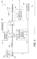
- the Fig. 3 schematically represents an all-optical and isotropic magnetometer, according to a second embodiment of the invention.
- the resonance is induced by a modulation of the wavelength of the pump beam.
- v 0 is the center frequency of the absorption line used for optical pumping (corresponding to the transition frequency between the levels 2 3 S 1 and 2 3 P 0 )
- ⁇ v a is the offset between the carrier frequency and the center frequency of the absorption line
- ⁇ v m is the modulation depth
- the magnetometer 300 does not include an intensity modulator 180 (acousto-optic or electro-optical).
- the laser diode 150 is powered via an AC / DC coupler 190 for modulating the supply current around a given operating point.
- the Fig. 4 represents an example of a power supply circuit of a laser diode, 450.
- This circuit comprises a DC power source, 410, a current generator, 420, generating an AC current having a determined time function, an RLC circuit , 430, serving as an AC / DC coupler (bias-T), a temperature controller 440 and said laser diode 450.
- the current applied to the laser diode is none other than the sum of the DC current supplied by the source 410 and AC current supplied by the generator 420.
- the modulation of the current flowing through the laser diode induces a modulation of the wavelength of the latter.
- the magnetometer comprises a first demodulation module, 140, for demodulating the signal from the photodetector at a first reference frequency f 1 .
- the pair constituted by the rectilinear polarizer 131 and the polarization rotator 135 can be replaced by a polarizer rectilinear mounted on a rotatable support and can be rotated by a non-magnetic motor.
- the magnetometer also comprises a second demodulation module, 160, for demodulating the signal from the photodetector at a second reference frequency f 2 .
- This demodulation makes it possible to slave the modulation frequency of the laser beam f m so as to create a resonance between the Zeeman sub-levels.
- the resonance signal is the continuous signal on which a low frequency modulation is added to mod_BF .
- An amplitude detection makes it possible to obtain an error signal.
- the antisymmetrical signal which makes it possible to slave the modulation frequency is the resonance signal on the harmonic 2 of f mod_BF .
- a third demodulation module, 120 for controlling the wavelength of the laser diode, via the laser controller 155, so that the carrier frequency v 0 + ⁇ v has been maintained at a constant value.
Landscapes
- Physics & Mathematics (AREA)
- Condensed Matter Physics & Semiconductors (AREA)
- General Physics & Mathematics (AREA)
- Investigating Or Analysing Materials By Optical Means (AREA)
- Measuring Magnetic Variables (AREA)
- Lasers (AREA)
Applications Claiming Priority (1)
| Application Number | Priority Date | Filing Date | Title |
|---|---|---|---|
| FR1556485A FR3038730B1 (fr) | 2015-07-08 | 2015-07-08 | Magnetometre tout optique et isotrope |
Publications (2)
| Publication Number | Publication Date |
|---|---|
| EP3115799A1 true EP3115799A1 (de) | 2017-01-11 |
| EP3115799B1 EP3115799B1 (de) | 2017-08-23 |
Family
ID=54329722
Family Applications (1)
| Application Number | Title | Priority Date | Filing Date |
|---|---|---|---|
| EP16178106.7A Active EP3115799B1 (de) | 2015-07-08 | 2016-07-06 | Optisch-isotropes magnetometer |
Country Status (3)
| Country | Link |
|---|---|
| US (1) | US10371764B2 (de) |
| EP (1) | EP3115799B1 (de) |
| FR (1) | FR3038730B1 (de) |
Cited By (3)
| Publication number | Priority date | Publication date | Assignee | Title |
|---|---|---|---|---|
| CN108287322A (zh) * | 2018-01-29 | 2018-07-17 | 中国人民解放军国防科技大学 | 一种无响应盲区的原子磁力仪及其测量外磁场的方法 |
| CN110988757A (zh) * | 2019-11-29 | 2020-04-10 | 山东航天电子技术研究所 | 基于原子磁力仪的微弱磁场矢量测量方法 |
| EP3702797A1 (de) * | 2019-02-28 | 2020-09-02 | Commissariat à l'énergie atomique et aux énergies alternatives | Isotropes, skalares und rein optisches magnetometer |
Families Citing this family (33)
| Publication number | Priority date | Publication date | Assignee | Title |
|---|---|---|---|---|
| FR3049702B1 (fr) | 2016-03-31 | 2018-04-13 | Commissariat A L'energie Atomique Et Aux Energies Alternatives | Dispositif de mesure de rotation, procede et centrale de navigation inertielle associes |
| FR3060114B1 (fr) | 2016-12-13 | 2019-05-17 | Commissariat A L'energie Atomique Et Aux Energies Alternatives | Procede d'aide a la navigation, produit programme d'ordinateur et centrale de navigation inertielle associes |
| US10634738B2 (en) * | 2017-07-31 | 2020-04-28 | Texas Instruments Incorporated | Zeeman splitting vector magnetometer apparatus and method |
| US10976386B2 (en) | 2018-07-17 | 2021-04-13 | Hi Llc | Magnetic field measurement system and method of using variable dynamic range optical magnetometers |
| US11262420B2 (en) | 2018-08-17 | 2022-03-01 | Hi Llc | Integrated gas cell and optical components for atomic magnetometry and methods for making and using |
| WO2020040882A1 (en) | 2018-08-20 | 2020-02-27 | Hi Llc | Magnetic field shaping components for magnetic field measurement systems and methods for making and using |
| US10627460B2 (en) | 2018-08-28 | 2020-04-21 | Hi Llc | Systems and methods including multi-mode operation of optically pumped magnetometer(s) |
| US11237225B2 (en) | 2018-09-18 | 2022-02-01 | Hi Llc | Dynamic magnetic shielding and beamforming using ferrofluid for compact Magnetoencephalography (MEG) |
| US11294008B2 (en) | 2019-01-25 | 2022-04-05 | Hi Llc | Magnetic field measurement system with amplitude-selective magnetic shield |
| WO2020167450A1 (en) | 2019-02-12 | 2020-08-20 | Hi Llc | Neural feedback loop filters for enhanced dynamic range magnetoencephalography (meg) systems and methods |
| FR3093816B1 (fr) | 2019-03-12 | 2021-04-16 | Commissariat Energie Atomique | Magnétomètre asservi en champ nul avec filtrage basse fréquence du champ de compensation |
| US11360164B2 (en) | 2019-03-29 | 2022-06-14 | Hi Llc | Integrated magnetometer arrays for magnetoencephalography (MEG) detection systems and methods |
| US11269027B2 (en) | 2019-04-23 | 2022-03-08 | Hi Llc | Compact optically pumped magnetometers with pump and probe configuration and systems and methods |
| US11131723B2 (en) | 2019-05-03 | 2021-09-28 | Hi Llc | Single controller for wearable sensor unit that includes an array of magnetometers |
| US11839474B2 (en) | 2019-05-31 | 2023-12-12 | Hi Llc | Magnetoencephalography (MEG) phantoms for simulating neural activity |
| US11131729B2 (en) | 2019-06-21 | 2021-09-28 | Hi Llc | Systems and methods with angled input beams for an optically pumped magnetometer |
| US11415641B2 (en) | 2019-07-12 | 2022-08-16 | Hi Llc | Detachable arrangement for on-scalp magnetoencephalography (MEG) calibration |
| WO2021026143A1 (en) | 2019-08-06 | 2021-02-11 | Hi Llc | Systems and methods having an optical magnetometer array with beam splitters |
| US11747413B2 (en) | 2019-09-03 | 2023-09-05 | Hi Llc | Methods and systems for fast field zeroing for magnetoencephalography (MEG) |
| US11474129B2 (en) | 2019-11-08 | 2022-10-18 | Hi Llc | Methods and systems for homogenous optically-pumped vapor cell array assembly from discrete vapor cells |
| US11604236B2 (en) | 2020-02-12 | 2023-03-14 | Hi Llc | Optimal methods to feedback control and estimate magnetic fields to enable a neural detection system to measure magnetic fields from the brain |
| US11980466B2 (en) | 2020-02-12 | 2024-05-14 | Hi Llc | Nested and parallel feedback control loops for ultra-fine measurements of magnetic fields from the brain using a neural detection system |
| US11872042B2 (en) | 2020-02-12 | 2024-01-16 | Hi Llc | Self-calibration of flux gate offset and gain drift to improve measurement accuracy of magnetic fields from the brain using a wearable neural detection system |
| US11801003B2 (en) | 2020-02-12 | 2023-10-31 | Hi Llc | Estimating the magnetic field at distances from direct measurements to enable fine sensors to measure the magnetic field from the brain using a neural detection system |
| US11977134B2 (en) | 2020-02-24 | 2024-05-07 | Hi Llc | Mitigation of an effect of capacitively coupled current while driving a sensor component over an unshielded twisted pair wire configuration |
| US11428756B2 (en) | 2020-05-28 | 2022-08-30 | Hi Llc | Magnetic field measurement or recording systems with validation using optical tracking data |
| US11766217B2 (en) | 2020-05-28 | 2023-09-26 | Hi Llc | Systems and methods for multimodal pose and motion tracking for magnetic field measurement or recording systems |
| WO2021242682A1 (en) | 2020-05-28 | 2021-12-02 | Hi Llc | Systems and methods for recording biomagnetic fields of the human heart |
| US11779251B2 (en) | 2020-05-28 | 2023-10-10 | Hi Llc | Systems and methods for recording neural activity |
| US11604237B2 (en) | 2021-01-08 | 2023-03-14 | Hi Llc | Devices, systems, and methods with optical pumping magnetometers for three-axis magnetic field sensing |
| US11803018B2 (en) | 2021-01-12 | 2023-10-31 | Hi Llc | Devices, systems, and methods with a piezoelectric-driven light intensity modulator |
| US12007454B2 (en) | 2021-03-11 | 2024-06-11 | Hi Llc | Devices, systems, and methods for suppressing optical noise in optically pumped magnetometers |
| CN113671424B (zh) * | 2021-07-23 | 2023-11-03 | 南方科技大学 | 一种磁场梯度测量方法以及原子磁力梯度仪系统 |
Citations (3)
| Publication number | Priority date | Publication date | Assignee | Title |
|---|---|---|---|---|
| EP0579537B1 (de) | 1992-07-16 | 1997-10-08 | Commissariat A L'energie Atomique | Magnetometer mit polarisiertem Licht und gesteuertem Hochfrequenzfeld |
| EP0656545B1 (de) | 1993-12-01 | 2002-01-30 | Commissariat A L'energie Atomique | Magnetometer mit polarisiertem Licht und gekoppeltem Hochfrequenzfeld |
| FR2984519A1 (fr) * | 2011-12-19 | 2013-06-21 | Commissariat Energie Atomique | Magnetometre a pompage optique integre et isotrope |
Family Cites Families (5)
| Publication number | Priority date | Publication date | Assignee | Title |
|---|---|---|---|---|
| JP5424578B2 (ja) * | 2007-06-05 | 2014-02-26 | キヤノン株式会社 | 磁気センシング方法、原子磁気センサ、及び磁気共鳴イメージング装置 |
| WO2009073256A2 (en) * | 2007-09-05 | 2009-06-11 | The Regents Of The Universtiy Of California | Optical atomic magnetometer |
| JP5972006B2 (ja) * | 2012-03-29 | 2016-08-17 | キヤノン株式会社 | 光ポンピング磁力計及び磁力測定方法 |
| JP2015021812A (ja) * | 2013-07-18 | 2015-02-02 | キヤノン株式会社 | 光ポンピング磁力計及び光ポンピング磁力測定方法 |
| JP6391370B2 (ja) * | 2014-08-29 | 2018-09-19 | キヤノン株式会社 | 光ポンピング磁力計及び磁気センシング方法 |
-
2015
- 2015-07-08 FR FR1556485A patent/FR3038730B1/fr active Active
-
2016
- 2016-07-06 EP EP16178106.7A patent/EP3115799B1/de active Active
- 2016-07-07 US US15/204,230 patent/US10371764B2/en active Active
Patent Citations (4)
| Publication number | Priority date | Publication date | Assignee | Title |
|---|---|---|---|---|
| EP0579537B1 (de) | 1992-07-16 | 1997-10-08 | Commissariat A L'energie Atomique | Magnetometer mit polarisiertem Licht und gesteuertem Hochfrequenzfeld |
| EP0656545B1 (de) | 1993-12-01 | 2002-01-30 | Commissariat A L'energie Atomique | Magnetometer mit polarisiertem Licht und gekoppeltem Hochfrequenzfeld |
| FR2984519A1 (fr) * | 2011-12-19 | 2013-06-21 | Commissariat Energie Atomique | Magnetometre a pompage optique integre et isotrope |
| FR2984519B1 (fr) | 2011-12-19 | 2014-02-21 | Commissariat Energie Atomique | Magnetometre a pompage optique integre et isotrope |
Non-Patent Citations (5)
| Title |
|---|
| CASSIMI A ET AL: "4HE OPTICAL PUMPING WITH INTENSITY MODULATED LASER LIGHT", JOURNAL DE PHYSIQUE 2 FRANCE,, vol. 1, no. 2, 1 February 1991 (1991-02-01), pages 123 - 133, XP009054650, ISSN: 1155-4312, DOI: 10.1051/JP2:1991151 * |
| GAWLIK W ET AL: "Nonlinear magneto-optical rotation with amplitude modulated light", APPLIED PHYSICS LETTERS, A I P PUBLISHING LLC, US, vol. 88, no. 13, 29 March 2006 (2006-03-29), pages 131108 - 131108, XP012080785, ISSN: 0003-6951, DOI: 10.1063/1.2190457 * |
| J. RUTKOWSKI ET AL: "Towards a miniature atomic scalar magnetometer using a liquid crystal polarization rotator", SENSORS AND ACTUATORS A., vol. 216, 13 May 2014 (2014-05-13), CH, pages 386 - 393, XP055272789, ISSN: 0924-4247, DOI: 10.1016/j.sna.2014.05.003 * |
| WU T ET AL: "A dead-zone free4He atomic magnetometer with intensity-modulated linearly polarized light and a liquid crystal polarization rotator", REVIEW OF SCIENTIFIC INSTRUMENTS, AIP, MELVILLE, NY, US, vol. 86, no. 10, 13 October 2015 (2015-10-13), pages 103105-1 - 103105-6, XP012201279, ISSN: 0034-6748, [retrieved on 19010101], DOI: 10.1063/1.4932528 * |
| ZHANG J-H ET AL: "Realization and Optimization of all-optical Cs atom magnetometer based on Bell-Bloom structure", GUANGDIANZI-JIGUANG - JOURNAL OF OPTRONICS-LASER, TIANJIN DAXUE JIDIAN FENXIAO, TIANJIN, CN, vol. 26, no. 2, 15 February 2015 (2015-02-15), pages 211 - 216, XP008180255, ISSN: 1005-0086 * |
Cited By (7)
| Publication number | Priority date | Publication date | Assignee | Title |
|---|---|---|---|---|
| CN108287322A (zh) * | 2018-01-29 | 2018-07-17 | 中国人民解放军国防科技大学 | 一种无响应盲区的原子磁力仪及其测量外磁场的方法 |
| CN108287322B (zh) * | 2018-01-29 | 2020-05-08 | 中国人民解放军国防科技大学 | 一种无响应盲区的原子磁力仪及其测量外磁场的方法 |
| EP3702797A1 (de) * | 2019-02-28 | 2020-09-02 | Commissariat à l'énergie atomique et aux énergies alternatives | Isotropes, skalares und rein optisches magnetometer |
| FR3093360A1 (fr) | 2019-02-28 | 2020-09-04 | Commissariat A L'energie Atomique Et Aux Energies Alternatives | Magnétomètre scalaire isotrope et tout optique |
| US11143722B2 (en) | 2019-02-28 | 2021-10-12 | Commissariat à l'énergie atomique et aux énergies alternatives | Isotropic and all-optical scalar magnetometer for measuring an ambient magnetic field |
| CN110988757A (zh) * | 2019-11-29 | 2020-04-10 | 山东航天电子技术研究所 | 基于原子磁力仪的微弱磁场矢量测量方法 |
| CN110988757B (zh) * | 2019-11-29 | 2022-06-07 | 山东航天电子技术研究所 | 基于原子磁力仪的微弱磁场矢量测量方法 |
Also Published As
| Publication number | Publication date |
|---|---|
| FR3038730A1 (fr) | 2017-01-13 |
| EP3115799B1 (de) | 2017-08-23 |
| US20170010337A1 (en) | 2017-01-12 |
| FR3038730B1 (fr) | 2017-12-08 |
| US10371764B2 (en) | 2019-08-06 |
Similar Documents
| Publication | Publication Date | Title |
|---|---|---|
| EP3115799B1 (de) | Optisch-isotropes magnetometer | |
| EP2795354B1 (de) | Isotropes magnetometer mit integriertem optischem pumpen | |
| EP0462002A1 (de) | Resonanzmagnetometer mit optischen Pumpen, das unterschiedliche Polarisationszustände verwendet | |
| Longdell et al. | Experimental demonstration of quantum-state tomography and qubit-qubit interactions for rare-earth-metal-ion-based solid-state qubits | |
| EP3524990A1 (de) | Vektor-magnetometer mit elliptischer polarisation | |
| EP0462000A1 (de) | Optisch gepumptes Resonanz-Magnetometer mit Verwendung einer Vielzahl von geschalteten Strahlen | |
| EP3454139B1 (de) | Optisches messsystem mit stabilisierter davll-steuerung und verfahren dazu | |
| EP3364204B1 (de) | Mittels ac-stark-effekt kontrolliertes nullfeld-magnetometer | |
| Akhmedzhanov et al. | Electromagnetically induced transparency in an isotopically purified Nd 3+: YLiF 4 crystal | |
| EP2261758B1 (de) | Mit Helium-3 angetriebene Atomuhr | |
| FR2853061A1 (fr) | Gyrolaser a etat solide stabilise | |
| WO2009074616A1 (fr) | Horloge atomique reglee par un champ statique et deux champs oscillants | |
| EP0656545B1 (de) | Magnetometer mit polarisiertem Licht und gekoppeltem Hochfrequenzfeld | |
| WO2005066586A1 (fr) | Gyrolaser a etat solide stabilise et a milieu laser anisotrope | |
| EP2541268B1 (de) | Hochauflösender vektorieller Hochpräzisionsmagnetometer | |
| EP2232200A1 (de) | Festkörper multioszillierender gyrolaser mit einem schnittkristallinen ausbeutemedium | |
| EP0461999A1 (de) | Optisch gepumpter Resonanzmagnetometer mit optischem Strahl mit gesteuerter Polarisation | |
| WO2022207905A1 (fr) | Methode d'asservissement d'un dispositif optique comprenant un laser et une cavite permettant de compenser une modulation d'amplitude introduite par un modulateur de phase | |
| EP3702797B1 (de) | Isotropes, skalares und rein optisches magnetometer | |
| FR2876448A1 (fr) | Gyrolaser a etat solide stabilise sans zone aveugle | |
| FR2894663A1 (fr) | Gyrolaser a etat solide active optiquement par biais alternatif | |
| EP3961236B1 (de) | Elliptisch polarisiertes magnetometer mit zwei hochfrequenz-feldkomponenten zur detektion der parametrischen absorptionsresonanz | |
| Chéron et al. | Improvement of the spatial amplitude isotropy of a 4He magnetometer using a modulated pumping beam | |
| EP4075156A1 (de) | Verfahren zum betrieb eines optisch gepumpten nullfeld-magnetometers, das in einem umgebungsfeld ungleich null betrieben wird | |
| FR2668862A1 (fr) | Procede de determination de l'amplitude d'un champ magnetique par pompage optique par laser et magnetometre pour la mise en óoeuvre du procede. |
Legal Events
| Date | Code | Title | Description |
|---|---|---|---|
| PUAI | Public reference made under article 153(3) epc to a published international application that has entered the european phase |
Free format text: ORIGINAL CODE: 0009012 |
|
| 17P | Request for examination filed |
Effective date: 20160706 |
|
| AK | Designated contracting states |
Kind code of ref document: A1 Designated state(s): AL AT BE BG CH CY CZ DE DK EE ES FI FR GB GR HR HU IE IS IT LI LT LU LV MC MK MT NL NO PL PT RO RS SE SI SK SM TR |
|
| AX | Request for extension of the european patent |
Extension state: BA ME |
|
| GRAP | Despatch of communication of intention to grant a patent |
Free format text: ORIGINAL CODE: EPIDOSNIGR1 |
|
| INTG | Intention to grant announced |
Effective date: 20170412 |
|
| GRAS | Grant fee paid |
Free format text: ORIGINAL CODE: EPIDOSNIGR3 |
|
| GRAA | (expected) grant |
Free format text: ORIGINAL CODE: 0009210 |
|
| AK | Designated contracting states |
Kind code of ref document: B1 Designated state(s): AL AT BE BG CH CY CZ DE DK EE ES FI FR GB GR HR HU IE IS IT LI LT LU LV MC MK MT NL NO PL PT RO RS SE SI SK SM TR |
|
| REG | Reference to a national code |
Ref country code: GB Ref legal event code: FG4D Free format text: NOT ENGLISH |
|
| REG | Reference to a national code |
Ref country code: CH Ref legal event code: EP |
|
| REG | Reference to a national code |
Ref country code: AT Ref legal event code: REF Ref document number: 921922 Country of ref document: AT Kind code of ref document: T Effective date: 20170915 |
|
| REG | Reference to a national code |
Ref country code: IE Ref legal event code: FG4D Free format text: LANGUAGE OF EP DOCUMENT: FRENCH |
|
| REG | Reference to a national code |
Ref country code: DE Ref legal event code: R096 Ref document number: 602016000283 Country of ref document: DE |
|
| REG | Reference to a national code |
Ref country code: NL Ref legal event code: MP Effective date: 20170823 |
|
| REG | Reference to a national code |
Ref country code: LT Ref legal event code: MG4D |
|
| REG | Reference to a national code |
Ref country code: AT Ref legal event code: MK05 Ref document number: 921922 Country of ref document: AT Kind code of ref document: T Effective date: 20170823 |
|
| PG25 | Lapsed in a contracting state [announced via postgrant information from national office to epo] |
Ref country code: FI Free format text: LAPSE BECAUSE OF FAILURE TO SUBMIT A TRANSLATION OF THE DESCRIPTION OR TO PAY THE FEE WITHIN THE PRESCRIBED TIME-LIMIT Effective date: 20170823 Ref country code: NO Free format text: LAPSE BECAUSE OF FAILURE TO SUBMIT A TRANSLATION OF THE DESCRIPTION OR TO PAY THE FEE WITHIN THE PRESCRIBED TIME-LIMIT Effective date: 20171123 Ref country code: HR Free format text: LAPSE BECAUSE OF FAILURE TO SUBMIT A TRANSLATION OF THE DESCRIPTION OR TO PAY THE FEE WITHIN THE PRESCRIBED TIME-LIMIT Effective date: 20170823 Ref country code: SE Free format text: LAPSE BECAUSE OF FAILURE TO SUBMIT A TRANSLATION OF THE DESCRIPTION OR TO PAY THE FEE WITHIN THE PRESCRIBED TIME-LIMIT Effective date: 20170823 Ref country code: LT Free format text: LAPSE BECAUSE OF FAILURE TO SUBMIT A TRANSLATION OF THE DESCRIPTION OR TO PAY THE FEE WITHIN THE PRESCRIBED TIME-LIMIT Effective date: 20170823 Ref country code: AT Free format text: LAPSE BECAUSE OF FAILURE TO SUBMIT A TRANSLATION OF THE DESCRIPTION OR TO PAY THE FEE WITHIN THE PRESCRIBED TIME-LIMIT Effective date: 20170823 Ref country code: NL Free format text: LAPSE BECAUSE OF FAILURE TO SUBMIT A TRANSLATION OF THE DESCRIPTION OR TO PAY THE FEE WITHIN THE PRESCRIBED TIME-LIMIT Effective date: 20170823 |
|
| PG25 | Lapsed in a contracting state [announced via postgrant information from national office to epo] |
Ref country code: PL Free format text: LAPSE BECAUSE OF FAILURE TO SUBMIT A TRANSLATION OF THE DESCRIPTION OR TO PAY THE FEE WITHIN THE PRESCRIBED TIME-LIMIT Effective date: 20170823 Ref country code: LV Free format text: LAPSE BECAUSE OF FAILURE TO SUBMIT A TRANSLATION OF THE DESCRIPTION OR TO PAY THE FEE WITHIN THE PRESCRIBED TIME-LIMIT Effective date: 20170823 Ref country code: IS Free format text: LAPSE BECAUSE OF FAILURE TO SUBMIT A TRANSLATION OF THE DESCRIPTION OR TO PAY THE FEE WITHIN THE PRESCRIBED TIME-LIMIT Effective date: 20171223 Ref country code: ES Free format text: LAPSE BECAUSE OF FAILURE TO SUBMIT A TRANSLATION OF THE DESCRIPTION OR TO PAY THE FEE WITHIN THE PRESCRIBED TIME-LIMIT Effective date: 20170823 Ref country code: RS Free format text: LAPSE BECAUSE OF FAILURE TO SUBMIT A TRANSLATION OF THE DESCRIPTION OR TO PAY THE FEE WITHIN THE PRESCRIBED TIME-LIMIT Effective date: 20170823 Ref country code: GR Free format text: LAPSE BECAUSE OF FAILURE TO SUBMIT A TRANSLATION OF THE DESCRIPTION OR TO PAY THE FEE WITHIN THE PRESCRIBED TIME-LIMIT Effective date: 20171124 Ref country code: BG Free format text: LAPSE BECAUSE OF FAILURE TO SUBMIT A TRANSLATION OF THE DESCRIPTION OR TO PAY THE FEE WITHIN THE PRESCRIBED TIME-LIMIT Effective date: 20171123 |
|
| PG25 | Lapsed in a contracting state [announced via postgrant information from national office to epo] |
Ref country code: DK Free format text: LAPSE BECAUSE OF FAILURE TO SUBMIT A TRANSLATION OF THE DESCRIPTION OR TO PAY THE FEE WITHIN THE PRESCRIBED TIME-LIMIT Effective date: 20170823 Ref country code: CZ Free format text: LAPSE BECAUSE OF FAILURE TO SUBMIT A TRANSLATION OF THE DESCRIPTION OR TO PAY THE FEE WITHIN THE PRESCRIBED TIME-LIMIT Effective date: 20170823 |
|
| REG | Reference to a national code |
Ref country code: DE Ref legal event code: R097 Ref document number: 602016000283 Country of ref document: DE |
|
| PG25 | Lapsed in a contracting state [announced via postgrant information from national office to epo] |
Ref country code: SM Free format text: LAPSE BECAUSE OF FAILURE TO SUBMIT A TRANSLATION OF THE DESCRIPTION OR TO PAY THE FEE WITHIN THE PRESCRIBED TIME-LIMIT Effective date: 20170823 Ref country code: SK Free format text: LAPSE BECAUSE OF FAILURE TO SUBMIT A TRANSLATION OF THE DESCRIPTION OR TO PAY THE FEE WITHIN THE PRESCRIBED TIME-LIMIT Effective date: 20170823 Ref country code: IT Free format text: LAPSE BECAUSE OF FAILURE TO SUBMIT A TRANSLATION OF THE DESCRIPTION OR TO PAY THE FEE WITHIN THE PRESCRIBED TIME-LIMIT Effective date: 20170823 Ref country code: EE Free format text: LAPSE BECAUSE OF FAILURE TO SUBMIT A TRANSLATION OF THE DESCRIPTION OR TO PAY THE FEE WITHIN THE PRESCRIBED TIME-LIMIT Effective date: 20170823 |
|
| PLBE | No opposition filed within time limit |
Free format text: ORIGINAL CODE: 0009261 |
|
| STAA | Information on the status of an ep patent application or granted ep patent |
Free format text: STATUS: NO OPPOSITION FILED WITHIN TIME LIMIT |
|
| REG | Reference to a national code |
Ref country code: FR Ref legal event code: PLFP Year of fee payment: 3 |
|
| 26N | No opposition filed |
Effective date: 20180524 |
|
| PG25 | Lapsed in a contracting state [announced via postgrant information from national office to epo] |
Ref country code: SI Free format text: LAPSE BECAUSE OF FAILURE TO SUBMIT A TRANSLATION OF THE DESCRIPTION OR TO PAY THE FEE WITHIN THE PRESCRIBED TIME-LIMIT Effective date: 20170823 |
|
| PG25 | Lapsed in a contracting state [announced via postgrant information from national office to epo] |
Ref country code: MT Free format text: LAPSE BECAUSE OF FAILURE TO SUBMIT A TRANSLATION OF THE DESCRIPTION OR TO PAY THE FEE WITHIN THE PRESCRIBED TIME-LIMIT Effective date: 20170823 |
|
| PG25 | Lapsed in a contracting state [announced via postgrant information from national office to epo] |
Ref country code: LU Free format text: LAPSE BECAUSE OF NON-PAYMENT OF DUE FEES Effective date: 20180706 Ref country code: MC Free format text: LAPSE BECAUSE OF FAILURE TO SUBMIT A TRANSLATION OF THE DESCRIPTION OR TO PAY THE FEE WITHIN THE PRESCRIBED TIME-LIMIT Effective date: 20170823 |
|
| REG | Reference to a national code |
Ref country code: BE Ref legal event code: MM Effective date: 20180731 |
|
| REG | Reference to a national code |
Ref country code: IE Ref legal event code: MM4A |
|
| PG25 | Lapsed in a contracting state [announced via postgrant information from national office to epo] |
Ref country code: IE Free format text: LAPSE BECAUSE OF NON-PAYMENT OF DUE FEES Effective date: 20180706 |
|
| PG25 | Lapsed in a contracting state [announced via postgrant information from national office to epo] |
Ref country code: BE Free format text: LAPSE BECAUSE OF NON-PAYMENT OF DUE FEES Effective date: 20180731 |
|
| REG | Reference to a national code |
Ref country code: CH Ref legal event code: PL |
|
| PG25 | Lapsed in a contracting state [announced via postgrant information from national office to epo] |
Ref country code: TR Free format text: LAPSE BECAUSE OF FAILURE TO SUBMIT A TRANSLATION OF THE DESCRIPTION OR TO PAY THE FEE WITHIN THE PRESCRIBED TIME-LIMIT Effective date: 20170823 |
|
| PG25 | Lapsed in a contracting state [announced via postgrant information from national office to epo] |
Ref country code: LI Free format text: LAPSE BECAUSE OF NON-PAYMENT OF DUE FEES Effective date: 20190731 Ref country code: PT Free format text: LAPSE BECAUSE OF FAILURE TO SUBMIT A TRANSLATION OF THE DESCRIPTION OR TO PAY THE FEE WITHIN THE PRESCRIBED TIME-LIMIT Effective date: 20170823 Ref country code: CH Free format text: LAPSE BECAUSE OF NON-PAYMENT OF DUE FEES Effective date: 20190731 |
|
| PG25 | Lapsed in a contracting state [announced via postgrant information from national office to epo] |
Ref country code: CY Free format text: LAPSE BECAUSE OF FAILURE TO SUBMIT A TRANSLATION OF THE DESCRIPTION OR TO PAY THE FEE WITHIN THE PRESCRIBED TIME-LIMIT Effective date: 20170823 Ref country code: MK Free format text: LAPSE BECAUSE OF NON-PAYMENT OF DUE FEES Effective date: 20170823 Ref country code: RO Free format text: LAPSE BECAUSE OF FAILURE TO SUBMIT A TRANSLATION OF THE DESCRIPTION OR TO PAY THE FEE WITHIN THE PRESCRIBED TIME-LIMIT Effective date: 20170823 Ref country code: HU Free format text: LAPSE BECAUSE OF FAILURE TO SUBMIT A TRANSLATION OF THE DESCRIPTION OR TO PAY THE FEE WITHIN THE PRESCRIBED TIME-LIMIT; INVALID AB INITIO Effective date: 20160706 |
|
| PG25 | Lapsed in a contracting state [announced via postgrant information from national office to epo] |
Ref country code: AL Free format text: LAPSE BECAUSE OF FAILURE TO SUBMIT A TRANSLATION OF THE DESCRIPTION OR TO PAY THE FEE WITHIN THE PRESCRIBED TIME-LIMIT Effective date: 20170823 |
|
| PGFP | Annual fee paid to national office [announced via postgrant information from national office to epo] |
Ref country code: GB Payment date: 20230724 Year of fee payment: 8 |
|
| PGFP | Annual fee paid to national office [announced via postgrant information from national office to epo] |
Ref country code: FR Payment date: 20230724 Year of fee payment: 8 Ref country code: DE Payment date: 20230720 Year of fee payment: 8 |