EP3115743A1 - Measurement system, measurement method, and vision chip - Google Patents
Measurement system, measurement method, and vision chip Download PDFInfo
- Publication number
- EP3115743A1 EP3115743A1 EP15758032.5A EP15758032A EP3115743A1 EP 3115743 A1 EP3115743 A1 EP 3115743A1 EP 15758032 A EP15758032 A EP 15758032A EP 3115743 A1 EP3115743 A1 EP 3115743A1
- Authority
- EP
- European Patent Office
- Prior art keywords
- projection
- image
- pattern
- subject
- imaging
- Prior art date
- Legal status (The legal status is an assumption and is not a legal conclusion. Google has not performed a legal analysis and makes no representation as to the accuracy of the status listed.)
- Granted
Links
- 238000005259 measurement Methods 0.000 title claims abstract description 88
- 238000000691 measurement method Methods 0.000 title claims description 16
- 238000003384 imaging method Methods 0.000 claims abstract description 106
- 230000008859 change Effects 0.000 claims description 23
- 238000000034 method Methods 0.000 claims description 17
- 238000012876 topography Methods 0.000 claims description 12
- 108091008695 photoreceptors Proteins 0.000 claims description 4
- 238000009792 diffusion process Methods 0.000 description 18
- 238000010586 diagram Methods 0.000 description 14
- 238000006243 chemical reaction Methods 0.000 description 12
- 238000012545 processing Methods 0.000 description 12
- 230000006870 function Effects 0.000 description 11
- NRNCYVBFPDDJNE-UHFFFAOYSA-N pemoline Chemical compound O1C(N)=NC(=O)C1C1=CC=CC=C1 NRNCYVBFPDDJNE-UHFFFAOYSA-N 0.000 description 7
- 238000004364 calculation method Methods 0.000 description 6
- 238000013507 mapping Methods 0.000 description 5
- 230000008901 benefit Effects 0.000 description 4
- 238000004590 computer program Methods 0.000 description 4
- 238000007796 conventional method Methods 0.000 description 3
- 239000003814 drug Substances 0.000 description 3
- 238000005516 engineering process Methods 0.000 description 3
- 238000012805 post-processing Methods 0.000 description 3
- 239000004065 semiconductor Substances 0.000 description 3
- 230000001133 acceleration Effects 0.000 description 2
- 238000004422 calculation algorithm Methods 0.000 description 2
- 230000002452 interceptive effect Effects 0.000 description 2
- 230000003287 optical effect Effects 0.000 description 2
- 230000003252 repetitive effect Effects 0.000 description 2
- 230000007423 decrease Effects 0.000 description 1
- 230000001419 dependent effect Effects 0.000 description 1
- 230000006866 deterioration Effects 0.000 description 1
- 238000011161 development Methods 0.000 description 1
- 239000004973 liquid crystal related substance Substances 0.000 description 1
- 238000012986 modification Methods 0.000 description 1
- 230000004048 modification Effects 0.000 description 1
- 238000012544 monitoring process Methods 0.000 description 1
- 230000002093 peripheral effect Effects 0.000 description 1
- 230000008569 process Effects 0.000 description 1
- 230000001360 synchronised effect Effects 0.000 description 1
- 230000002123 temporal effect Effects 0.000 description 1
- 238000012546 transfer Methods 0.000 description 1
- 239000013598 vector Substances 0.000 description 1
- 230000000007 visual effect Effects 0.000 description 1
Images







Classifications
-
- G—PHYSICS
- G01—MEASURING; TESTING
- G01B—MEASURING LENGTH, THICKNESS OR SIMILAR LINEAR DIMENSIONS; MEASURING ANGLES; MEASURING AREAS; MEASURING IRREGULARITIES OF SURFACES OR CONTOURS
- G01B11/00—Measuring arrangements characterised by the use of optical techniques
- G01B11/24—Measuring arrangements characterised by the use of optical techniques for measuring contours or curvatures
- G01B11/25—Measuring arrangements characterised by the use of optical techniques for measuring contours or curvatures by projecting a pattern, e.g. one or more lines, moiré fringes on the object
- G01B11/2509—Color coding
-
- G—PHYSICS
- G01—MEASURING; TESTING
- G01B—MEASURING LENGTH, THICKNESS OR SIMILAR LINEAR DIMENSIONS; MEASURING ANGLES; MEASURING AREAS; MEASURING IRREGULARITIES OF SURFACES OR CONTOURS
- G01B11/00—Measuring arrangements characterised by the use of optical techniques
- G01B11/24—Measuring arrangements characterised by the use of optical techniques for measuring contours or curvatures
- G01B11/25—Measuring arrangements characterised by the use of optical techniques for measuring contours or curvatures by projecting a pattern, e.g. one or more lines, moiré fringes on the object
- G01B11/2513—Measuring arrangements characterised by the use of optical techniques for measuring contours or curvatures by projecting a pattern, e.g. one or more lines, moiré fringes on the object with several lines being projected in more than one direction, e.g. grids, patterns
-
- G—PHYSICS
- G01—MEASURING; TESTING
- G01B—MEASURING LENGTH, THICKNESS OR SIMILAR LINEAR DIMENSIONS; MEASURING ANGLES; MEASURING AREAS; MEASURING IRREGULARITIES OF SURFACES OR CONTOURS
- G01B11/00—Measuring arrangements characterised by the use of optical techniques
- G01B11/24—Measuring arrangements characterised by the use of optical techniques for measuring contours or curvatures
- G01B11/25—Measuring arrangements characterised by the use of optical techniques for measuring contours or curvatures by projecting a pattern, e.g. one or more lines, moiré fringes on the object
- G01B11/2536—Measuring arrangements characterised by the use of optical techniques for measuring contours or curvatures by projecting a pattern, e.g. one or more lines, moiré fringes on the object using several gratings with variable grating pitch, projected on the object with the same angle of incidence
Definitions
- the present application relates to a measurement system, a measurement method used in the measurement system, and a vision chip.
- PTL 1 discloses such a technology.
- a measurement system includes: a projection apparatus that projects, onto a subject, first pattern light indicating a first pattern projection image including a first pattern image corresponding to a certain bit in gray code obtained by gray coding projection coordinates stipulated by a projection coordinate system, and a second pattern image having the same cycle as the first pattern image, but having a different phase from the first pattern image, following a projection sequence where projections of the first and second pattern images coexist; and at least one imaging apparatus that images the first pattern light and generates an imaged image.
- a computer-readable storage medium may include non-volatile recording media, such as a CD-ROM (Compact Disc - Read Only Memory) and so forth.
- tracking capabilities of the motion of objects, and robustness can be improved.
- the measurement system 800 includes an imaging apparatus 801, a light source 802, and a slit board 803.
- the slit board 803 has slits with different patterns based on various gray codes, such as patterns 803a, 803b, and 803c, which exhibit gray codes.
- the imaging apparatus 801 images light corresponding to the patterns 803a, 803b, and 803c, and generates images 805a, 805b, and 805c.
- the images 805a, 805b, and 805c make up an image group 805.
- NPL 1 discloses a technique for high-speed 3D shape measurement technique using light pattern projection.
- the measurement system in NPL 1 has an imaging apparatus, a light source, and a projection apparatus including a lens and digital micro-mirror device.
- the imaging apparatus has a function of performing high-speed photography.
- the imaging apparatus can perform high-speed photography at 6000 fps.
- the projection apparatus can project binary patterns having 1024 ⁇ 768 pixels at 6000 fps or more. It can be said that a feature thereof in comparison with PTL 1 is the point that the light source and slit board have been replaced with the projection apparatus having the digital micro-mirror device which can be controlled from a calculator at an extremely fast rate.
- a pattern obtained by performing Manchester coding of bits obtained by gray coding X-coordinates of a 1024 ⁇ 768 image is set in the digital micro-mirror device at 6000 fps.
- the pattern is projected on a projection object, and the imaging apparatus shoots the projection object upon which the pattern has been projected at 6000 fps.
- the X-coordinate is in a range of 0 to 1023, and accordingly each coordinate is expressed in terms of 10 bits. Further, by performing Manchester coding, each coordinate is expressed in terms of 20 bits. Accordingly, the X coordinates are obtained from 20 frames of imaged images. The distance to the projection object can be obtained for each pixel by triangulation. The results of imaging are transmitted to a calculating apparatus (e.g., a personal computer) and analyzed. New X-coordinate bits can be obtained for recalculation every two frames, by Manchester coding. Accordingly, 3D measurement at resolution of 3000 fps can be realized as the final throughput.
- a calculating apparatus e.g., a personal computer
- a high-speed vision space can be defined where the amount of motion of an object between frames is restricted to within 1 pixel within an imaging pixel space, by performing imaging with regard to the system dynamics of an imaging space at a sufficiently fast frame rate, and such an image processing algorithm is created.
- NPL 1 suggests the possibility of realizing three-dimensional measurement of a moving object at a high frame rate, using a projection apparatus and an imaging apparatus.
- NPL 1 in a case where the projected image of the projection apparatus has 1024 pixels in the X-coordinate direction, for example, 20 frames are used to transmit 10 bits work of X-coordinates. It is true that new three-dimensional measurement results are updated each time a new bit is finalized, so three-dimensional measurement can be performed at a rate of 3000 fps. However, these results include the results before the 20 frames by imaging at the rate of 6000 fps, so the actual time resolution is around 300 fps, which is 1/20 the projection rate. Consequently, the moment speed of a subject which can actually be measured is markedly restricted.
- the frame rates of the projection apparatus and imaging apparatus are restricted to be sufficient for the movement speed of a subject to be measured.
- a new pattern coding system is provided with improved tracking capabilities of the motion of objects, and further improved robustness. For example, in a case of measuring a human body, even in a case of assuming a subject that is performing an exercise such as in sports or the like, movement exceeding a speed of 30 meters per second is extremely unlikely. If the object of measuring the human body is for medical purposes, the subject speed can be restricted to even lower speeds.
- a measurement system includes: a projection apparatus that projects, onto a subject, first pattern light indicating a first pattern projection image including a first pattern image corresponding to a certain bit in gray code obtained by gray coding projection coordinates stipulated by a projection coordinate system, and a second pattern image having the same cycle as the first pattern image, but having a different phase from the first pattern image, following a projection sequence where projections of the first and second pattern images coexist; and at least one imaging apparatus that images the first pattern light and generates an imaged image.
- a measurement system can be provided which can improve tracking capabilities of the motion of objects and improve robustness.
- the measurement system may further include a computing device that measures three-dimensional shape information of the subject based on the imaged image.
- three-dimensional shape information of the subject can be measured in real-time.
- the projection apparatus may project, upon the subject, second pattern light indicating a second pattern projection image including the first pattern image but not including the second pattern image, for one frame period or more, and thereafter projects the first pattern light on the subject for two frame periods or more.
- the computing device may measure second three-dimensional shape information indicating absolute distance to the subject, based on the imaged image of the second pattern light projected on the subject that has been imaged by the imaging apparatus, measure first three-dimensional shape information indicating relative amount of change of the subject based on the imaged image of the first pattern light projected on the subject that has been imaged by the imaging apparatus, and update the second three-dimensional shape information based on the first three-dimensional shape information.
- the first pattern projection image may further include a third pattern image that differs from the first and second pattern images, and the projection sequence further include projection of the third pattern image.
- the pixel value of the pixel within the third pattern image may be 0 when the pixel value of the pixel is 1 within both the first and second pattern images
- the pixel value of the pixel within the third pattern image may be 1 when the pixel value of the pixel is 0 within both the first and second pattern images.
- the pixel value of the pixel within the third pattern image may be a value of 0 or 1 less frequently occurring in past frames of the third pattern image.
- the computing device may selectively switch mixing of projection of the second pattern image in the projection sequence, in accordance with three-dimensional amount of change of the subject.
- the speed of the measurement system can be restricted.
- restriction can be applied to acceleration of the moving object as well.
- the computing device may selectively decide the certain bit in gray code in accordance with three-dimensional amount of change of the subject.
- the range over which the amount of change of the subject can be tracked can be dynamically changed.
- the computing device independently from measurement of the three-dimensional shape of the subject, may search for amount of two-dimensional movement, and decode an image indicating the gray code imaged by the at least one imaging apparatus, referencing the two-dimensional amount of movement.
- the image used for searching for the two-dimensional amount of movement may be obtained by compositing a plurality of images acquired by the three-dimensional shape measurement.
- the composited image can be used for two-dimensional image processing such as motion searching, without new photography being performed.
- the computing device may decode the imaged image, and convert the three-dimensional shape information obtained from the imaging coordinate system into three-dimensional shape information in the projection coordinate system, from the correlation between the decoded projection coordinates and the imaging pixel coordinates stipulated by the imaging coordinate system of the at least one imaging apparatus.
- the at least one imaging apparatus may be a plurality of imaging apparatuses, the plurality of imaging apparatuses imaging the first pattern light complementing the imaging range of the subject of each other.
- the computing device may decode the imaged image, and generate a moiré topography image from the correlation between the decoded projection coordinates and the imaging pixel coordinates stipulated by the imaging coordinate system of the at least one imaging apparatus.
- a moiré topography image can be obtained as a moving image, and the present disclosure can be suitably applied to the field of medicine.
- the computing device may generate a projection image based on the three-dimensional shape information, the projection apparatus projecting projection light indicating the projection image on the subject.
- the present measurement system can be made to function as a projection system.
- a vision chip used in the above measurement system includes a plurality of unit pixels.
- Each of the plurality of unit pixels includes a photoreceptor that receives light and generates charge, a first and second charge accumulating unit that respectively accumulate a first and second charge obtained by the photoreceptor at different points-in-time, and a comparator that compares an amount of the first charge accumulated in the first charge accumulating unit with an amount of the second charge accumulated in the second charge accumulating unit, and generates a first bit indicating the relation in magnitude between the first and second amounts of charge, and a second bit indicating whether or not the difference between the first and second amounts of charge is within a predetermined range, based on the comparison results.
- a measurement method used in a measurement system including a projection apparatus and an imaging apparatus, includes: projecting, using the projecting apparatus, onto a subject to be measured, second pattern light indicating a first pattern projection image including a first pattern image corresponding to a certain bit in gray code obtained by gray coding projection coordinates stipulated by a projection coordinate system, and not including a second pattern projection image having the same cycle as the first pattern image, but having a different phase from the first pattern image, for one frame period or more, and thereafter projecting first pattern light indicating a first pattern projection image including the first and second pattern images on the subject for two frame periods or more; measuring second three-dimensional shape information indicating absolute distance to the subject, based on the imaged image of the second pattern light projected on the subject that has been imaged by the imaging apparatus; measuring first three-dimensional shape information indicating relative amount of change of the subject based on the imaged image of the first pattern light projected on the subject that has been imaged by the imaging apparatus; and updating the second three-dimensional shape information based
- three-dimensional measurement results can be obtained with higher time resolution as to the frame rate of the projection apparatus, as compared to conventional arrangements.
- a measurement method includes: a first projection step, where projection, onto a subject, of first data indicating data of a certain bit in gray code obtained by gray coding projection coordinates stipulated by a projection coordinate system, is repeated at a first cycle; a second projection step where projection of second data onto the subject is repeated at the same cycle as the first cycle; and a step of imaging the first data and second data projected into the subject.
- a first image is consecutively employed as the first data for a first number of times and thereafter a second image is consecutively employed as the first data for the first number of times, which is repeatedly performed.
- a third image is consecutively employed as the second data for the first number of times and thereafter a fourth image is consecutively employed as the second data for the first number of times, which is repeatedly performed.
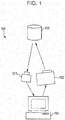
- Fig. 1 schematically illustrates an example of a schematic configuration of the measurement system 100.
- the measurement system 100 includes an imaging apparatus 101, a projection apparatus 102, and a calculator 104.
- the projection apparatus 102 projects, on a subject, a first pattern light indicating a first pattern projection image including a first pattern image and a second pattern image, in accordance with a projection sequence where projection of first and second pattern images coexist.
- the first pattern image is an image corresponding to a particular bit in gray code, obtained by gray coding projection coordinates stipulated by a projection coordinate system.
- the second pattern image is an image having the same cycle as the first pattern image, but having a different phase from the first pattern image.
- projection coordinate system means a coordinate system that identifies the coordinates of the pixels in the pattern images for projection. Also, coordinates which identify the pixels of the pattern images are called "projection coordinates" of the projection coordinate system.
- the projection apparatus 102 includes a light source, lens optical system, and so forth.
- the projection apparatus 102 has resolution of 32 pixels in the X-axis direction and 28 pixels in the Y-axis direction. Note however, that this resolution is a specification to simplify description.
- DLP projectors There are known DLP projectors and so forth, for example.
- a DLP project may have resolution of 1920 pixels in the X-axis direction and 1080 pixels in the Y-axis direction.
- Binary patterns exceeding 20000 fps can be output using such a DLP projector.
- a wide range of such products of this type can be used for the projection apparatus 102.
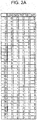
- Fig. 2A illustrates a 5-bit gray code obtained by gray coding the values of 0 through 31 for the X-coordinates.
- Fig. 2B illustrates a 5-bit auxiliary code corresponding to 5-bit gray code.
- Fig. 3 illustrates a part of pattern images corresponding to 5-bit gray code.
- the gray code illustrated in Fig. 2A is obtained by coding 32 types of values by the 5 bits of bit 0 through bit 4. Due to the nature of gray code, only one bit changes between adjacent values.
- (X4a) indicates a pattern image corresponding to bit 4 of the X-coordinates gray code value
- (X4b) indicates a pattern image obtained by inverting (X4a).
- (X3a) indicates a pattern image corresponding to bit 3 of the X-coordinates gray code value
- (X2b) indicates a pattern image obtained by inverting (X2a).
- (X2a) indicates a pattern image corresponding to bit 2 of the X-coordinates gray code value
- (X2b) indicates a pattern image obtained by inverting (X2a).
- (Y4a) indicates a pattern image corresponding to bit 4 of the Y-coordinates gray code value
- (Y4b) indicates a pattern image obtained by inverting (Y4a).
- (Y3a) indicates a pattern image corresponding to bit 3 of the X-coordinates gray code value
- (Y2b) indicates a pattern image obtained by inverting (Y2a).
- (Y2a) indicates a pattern image corresponding to bit 2 of the Y-coordinates gray code value
- (Y2b) indicates a pattern image obtained by inverting (Y2a).
- corresponding pattern images and inverted pattern images may exist for bit 1 and 0 of the X-coordinates and Y-coordinates as well.
- the projection apparatus 102 sequentially projects these patterns on a subject 103.
- the projection apparatus 102 projects projection light, including projection of images according to the gray code and auxiliary code, following a later-described projection sequence.
- the imaging apparatus 101 sequentially images the projected pattern light, and generates an imaged image.
- the imaging apparatus 101 includes an imaging coordinate system which stipulates imaging pixel coordinates.
- the imaging apparatus 101 includes an imaging sensor, lens optical system, and so forth.
- imaging coordinate system means a coordinate system that identifies the coordinates of the pixels in the imaged images acquired by the imaging apparatus 101.
- the coordinates of the pixels of the imaged images are called "imaging coordinates" to distinguish from "projection coordinates" of the imaging coordinate system.
- the calculator 104 has functions of controlling the entire measurement system 100. For example, the calculator 104 performs measurement of three-dimensional shape information of the subject, based on imaged images.
- the calculator 104 may be realized by a computer, an operation device of which a processor is representative, or by a semiconductor integrated circuit, for example. Examples of semiconductor integrated circuits include ASIC (Application Specific Integrated Circuit) and FPGA (Field Programmable Gate Array), for example.
- a computer program which exhibits the functions of the components may be loaded in the memory, with the functions of the components being realized by a processor within the semiconductor integrated circuit successively executing the computer program.
- Fig. 4 illustrates an example of a functional block configuration of the calculator 104.
- the calculator 104 includes an image output unit 400, an image input unit 410, a difference calculation unit 420, a frame memory unit 430, a code decoding unit 440, a coordinate conversion unit 450, a coordinate conversion memory unit 460, a coordinate interpolation unit 470, content generating unit 480, a pattern generating unit 490, and the image output unit 400.
- the memory units in the calculator 104 may be configured including RAM or the like, for example.
- the coordinate conversion unit 450, coordinate conversion memory unit 460, coordinate interpolation unit 470, and content generating unit 480 may be optionally provided.
- the measurement system 100 may function as a projection system, which will be described later. The functions which these functional blocks have can be implemented in the calculator 104 when functioning as a projection system.
- the image input unit 410 receives imaged images (image data) imaged by the imaging apparatus 101, synchronously with the image output unit 400.
- the image input unit 410 transmits the received image data to the difference calculation unit 420.
- the difference calculation unit 420 calculates the difference in pattern images representing inverted bits and non-inverted bits for each bit of the gray code, thereby decoding the Manchester code, and outputs data to the code decoding unit 440 every two frames.
- the difference calculation unit 420 writes the image data to the frame memory unit 430. If the imaged data is an X and Y coordinate bit-inverted image, the difference calculation unit 420 reads to the non-bit-inverted image written to the frame memory unit 430 before, and finds the difference between the two. By finding the difference, the "0"s and "1"s of the projection light can be distinguished without dependency on the color of the subject or the ambient light. A region where the difference is a predetermined value or lower is determined as being a region where no projection light has been projected, and that region can be eliminated from being a region which is the object of measurement.
- a code decoding memory unit 441 is provided with a write region for each pixel of the imaging apparatus 101.
- the bit values of the coordinate data that has been gray coded is written to that write region in increments of bits. This operation is sequentially executed during the exposure time of the imaging apparatus 101.
- the code decoding unit 440 reads out the data recorded in the code decoding memory unit 441 in increments of bits.
- the code decoding unit 440 updates a certain bit in accordance with information indicating the type of pattern currently being output by the pattern generating unit 490 (pattern type information), and writes the updated data in increments of bits to the aforementioned write region within the code decoding memory unit 441.
- the code decoding unit 440 Upon having received imaging data based on the second pattern light indicating the second pattern projection image, the code decoding unit 440 decodes the imaging data and generates second three-dimensional shape information representing the relative distance information to the subject. Upon having received imaging data based on the first pattern light indicating the first pattern projection image, the code decoding unit 440 decodes that image data, and generates first three-dimensional shape information representing relative amount of change of the subject. At this time, the code decoding unit 440 corrects (updates) the absolute distance information to the subject based on the amount of change. That is to say, the code decoding unit 440 updates the second three-dimensional shape information based on the first three-dimensional shape information.
- the code decoding unit 440 finally reconverts the gray code coordinate data recorded in the code decoding memory unit 441 into binary, and outputs to the coordinate conversion unit 450.
- the processing so far it can be found which pixel of the projection apparatus 102 that projection light, imaged at a certain pixel of the imaging apparatus 101, has been projected from. That is to say, the correlation between projection coordinates and imaging coordinates can be known. Accordingly, once the relative positional relationship between the imaging apparatus 101 and the projection apparatus 102 is known, the distance to the subject can be found by triangulation for each imaged pixel. However, the obtained information is distance information corresponding to the imaging pixels of the imaging apparatus 101 accordingly, that information is converted into distance information corresponding to the pixel coordinates of the projection apparatus 102 in the present embodiment.
- the coordinate conversion unit 450 writes the data received from the code decoding unit 440 into a region of the coordinate conversion memory unit 460 identified by an address corresponding to the projection coordinates of the projection apparatus 102. Thereafter, the coordinate conversion unit 450 reads out the second three-dimensional shape information from the coordinate conversion memory unit 460, in order of X-coordinates and Y-coordinates of the projection apparatus 102, thereby generating distance information to the subject corresponding to the projection coordinates of the projection apparatus 102.
- each light corresponding to a certain plurality of pixels can be imaged by one imaging pixel of the imaging apparatus 101.
- the projection pixels with no corresponding points are included on the pixel coordinates of one of the two adjacent projection pixels, due to the nature of gray code, so one projection pixel is in a state of having no correlating destination.
- the coordinate interpolation unit 470 receives distance information corresponding to the projection coordinates of the projection apparatus 102, from the coordinate conversion unit 450.
- the coordinate interpolation unit 470 interpolates distance information regarding projection coordinates having no distance information. This is limited to portions where there are a certain number of projection coordinates having distance information which can be interpolated present in the perimeter thereof, and is performed using an interpolation technique such as linear interpolation or the like, from the distance information of the peripheral coordinates.
- the coordinate interpolation unit 470 outputs the distance information from the projection coordinate system to the content generating unit 480.
- the content generating unit 480 generates video content for projection.
- the content generating unit 480 processes video content recording beforehand based on the distance information received from the coordinate interpolation unit 470, and outputs the processed video content to the image output unit 400.
- the processed video content may be referred to as "post-processing video content", to distinguish from the video content before processing that has been recorded beforehand.
- the content generating unit 480 generates video content accurately corresponding to the distance to the subject, without any coordinate deviation.
- the content generating unit 480 outputs the post-processing video content for projection to the image output unit 400.
- the pattern generating unit 490 has a basic pattern generating unit 491, an auxiliary pattern generating unit 492, and a selector 493.
- the basic pattern generating unit 491 generates a basic pattern indicating gray code obtained by gray coding the projection coordinates stipulated by the projection coordinate system.
- the first image pattern is included in the basic pattern.
- the auxiliary pattern generating unit 492 generates an auxiliary pattern having the same cycle as the basic pattern, but having a different phase from the basic pattern.
- the second image pattern is included in the auxiliary pattern.
- a basic pattern or auxiliary pattern is selected by the selector 493, and output to the image output unit 400.
- the auxiliary pattern and basic pattern are selectively intermingled by switching of the selector 493 in accordance with the three-dimensional amount of change of the subject 103. As a result, a projection sequence where projection of basic patterns and auxiliary patterns coexist is decided.
- the image output unit 400 outputs video content generated by the content generating unit 480, and projection patterns including basic patterns and auxiliary patterns, generated by the pattern generating unit 490, to the projection apparatus 102.
- the projection apparatus 102 projects projection light indicating the post-processing video content on the subject 103.
- Fig. 5 is a flowchart of the measurement method of the measurement system 100.
- the projection apparatus 102 projects second pattern light, indicating a second pattern projection image that includes a first pattern image does not include a second pattern image, on the subject for a period of 1 frame or longer.
- a non-moving object or the like that has a reference plane is set at the position of the subject 103.
- the projection apparatus 102 projects pattern light indicating the pattern image (X4a) in Fig. 3 on the subject 103.
- the imaging apparatus 101 then images this pattern light, and acquires a first calibration image.
- the projection apparatus 102 projects pattern light indicating the pattern image (X4b) in Fig. 3 on the object.
- the imaging apparatus 101 then images this pattern light, and acquires a second calibration image.
- a region where difference is small can be determined to be a region where no projection light has been cast.
- a region where difference is great can be determined to be a region where projection light has been cast, and projection coordinates can be decoded from the code of this difference.
- the difference in the X axial direction as to the reference plane is converted into distance by triangulation.
- Y-axis directional setup error, lens distortion, and so forth may be obtained beforehand in the initial calibration.
- the initial calibration is unnecessary.
- the projection apparatus 102 projects the first pattern light, indicating the first pattern projection image including the first pattern image and second pattern image, on the subject for a period of 2 frames or longer.
- the projection apparatus 102 projects pattern light on the subject following a projection sequence with image projection corresponding to basic patterns and auxiliary patterns coexisting.
- the projection apparatus 102 projects pattern images of each of non-inverted bits and inverted bits.
- the imaging apparatus 101 images the first pattern light.
- the calculator 104 acquires the first three-dimensional shape information from the imaged image based on the first pattern light.
- the calculator 104 updates the second three-dimensional shape information based on the first three-dimensional shape information. Accordingly, a moving object can be tracked based on relative amount of change.
- Fig. 6A illustrates a projection sequence in conventional three-dimensional measurement.
- the conventional projection sequence performs measurement while sequentially projecting projection light for bit 0 through bit 5 for X-coordinates, Two frames including the inverted pattern image are used in measurement of 1 bit, so in the example illustrated in Fig. 6A , measurement is performed in 10-frame cycles.
- the past 5 bits worth is tabulated and X coordinates are acquired, each time measurement results of a new bit are acquired.
- the distance to the subject 103 can be obtained by triangulation.
- this is dependent on images of the past 10 frames, so deterioration in time resolution is unavoidable.
- a certain bit in auxiliary code is used in addition to the gray code illustrated in Fig. 6A that is used in conventional measurement.
- the present embodiment assumes that the distance of object of measurement does not change one pixel worth or more in a section for measuring 3 bits, i.e., in 6 frame sections.
- a measurement method of using bit 0 in auxiliary code corresponding to bit 0 in gray code is described.
- Fig. 6B illustrates a projection sequence in the three-dimensional measurement according to the present embodiment.
- the imaging sequence according to the present embodiment has increment sequences determined by sections of measuring 3 bits.
- An increment sequence includes bit 0 of the gray code and bit 0 of the auxiliary code corresponding thereto.
- the increment sequence also includes bits other than bit 0 of the gray code.
- pattern light indicating an image corresponding to bit 0 of the gray code, bit 0 of the auxiliary code, and bit 1 of the gray code is projected in this order.
- pattern light indicating an image corresponding to bit 0 of gray code, bit 0 of auxiliary code, bit 2 of gray code, bit 0 of gray code, bit 0 of auxiliary code, bit 3 of gray code, bit 0 of gray code, bit 0 of auxiliary code, and bit 4 of gray code is projected in this order. Accordingly, 24 frames are required for all bits to be included. Thereafter, such projection is repeatedly executed.
- auxiliary code is inserted between gray code in the projection sequence according to the present embodiment.
- the absolute value of distance to a subject first appearing in a frame is obtained with a delay of 24 frames. Thereafter, the relative value of change in distance can be obtained every 6 frames. Accordingly, the charge in distance to a subject regarding which the absolute value has been once captured can be tracked using 6 frames. Thus, high time resolution can be obtained as compared to conventional techniques.
- Bit 1 or bit 2 or the like may be used for tracking relative amount of movement, in accordance with the amount of moment of the moving object to be measured.
- a certain bit of gray code may be made to be selectably decidable in accordance with the three-dimensional amount of change of the subject.
- using bit 1 of the auxiliary code enables a moving object changing within a range of 3 pixels to be tracked, as illustrated in Fig. 2B .
- using bit 2 of the auxiliary code enables a moving object changing within a range of 7 pixels to be tracked.
- mixing projection of auxiliary pattern images in the projection sequence while measuring the movement speed of the subject i.e., whether or not to use auxiliary patterns
- the position of the bit in the auxiliary pattern that use used may be dynamically changed.
- Many systems can actually restrict their own speed.
- the acceleration of the moving object by also be subject to restriction. Change in speed does not occur beyond a certain level, so the subject can be tracked within a certain range even if the bit in the auxiliary pattern is dynamically changed.
- a greater number of pattern images can be superimposed in one frame period by changing the color or wavelength for each pattern image, instead of projecting pattern light indicating pattern images in increments of frames.
- the measurement system 100 has one imaging apparatus 101.
- the measurement system 100 may be provided with multiple imaging apparatuses 101.
- the multiple imaging apparatuses 101 can image pattern light so as to compensate for each others' imaging range of the subject 103. Accordingly, occlusion regions where projection light is cast but imaging cannot be performed, can be reduced.
- Disposing at least two imaging apparatuses 101 on both sides of the projection apparatus 102 enables occlusion regions, where projection light is cast but imaging cannot be performed, to be reduced.
- the subject 103 may change in the X-Y coordinate directions on the imaging plane, as well.
- the calculator 104 may, independently from three-dimensional shape measurement of the subject, search for the amount of two-dimensional movement, and decode an image indicating gray code imaged by the imaging apparatus 101, referencing the amount of two-dimensional movement.
- Movement searching by two-dimensional image processing has been conventionally known as a method to track change in the X-Y coordinate directions.
- Obtaining motion vectors of the pixels by conventional movement searching, and decoding gray code based corresponding pixel positions in pas frames, enables an even higher level of measurement to be obtained.
- the amount of movement of the subject can be restricted to within one pixel in high-speed vision space, so even if searching is performed in all directions, the range of the search is no larger than within a 3 x 3 range.
- a method will be proposed to obtaining an image to be handled in two-dimensional image processing, by compositing an imaged image of a non-inverted-bit pattern for projection, such as gray code or an auxiliary pattern or the like, and an imaged image of the inverted-bit pattern thereof.
- a non-inverted-bit pattern for projection such as gray code or an auxiliary pattern or the like
- NPL 1 Using images of non-inverted-bit patterns and inverted-bit patterns is the technique described in NPL 1 to improve robustness by Manchester coding.
- Manchester coding the frequency of occurrence of 0s and 1s in the temporal direction is equal at each bit. Accordingly, compositing multiple measurement images yields images equivalent to images obtained in a state where a constant amount of light is projected to all pixels.
- the composited image can be used for two-dimensional image processing such as movement searching and so forth, without having to perform new photography.
- the projection sequence further includes projection of a third image frame.
- Fig. 7 illustrates the way a projection frame appears when acquiring 0 bit data of X-coordinates.
- first image frame means a frame of an image corresponding to bit 0 of the gray code in Fig. 2A .
- the term second image frame means a frame of an image corresponding to bit 0 of the auxiliary pattern in Fig. 2B .
- the pixel value of the pixel corresponding to that pixel is 0 when the pixel value of the pixel is 1 within both the first and second image frames, and the pixel value of the pixel corresponding to that pixel is 1 when the pixel value of the pixel is 0 within both the first and second image frames.
- pixel values of pixels where the pixel values of both the first and second image frames differ can be handled as a don't-care value. These image frames may be projected in random order.
- each pixel will include 0 and 1, so a place where projection light is not being cast can be detected based on the imaging results. 0/1 determination can be made at places where projection light is being cast.
- a value of 0 or 1 less frequently occurring in past frames of the third image frame may be allocated to the pixel within the third image frame.
- the frequency of occurrence of 0s and 1 s can be made uniform at each pixel, whereby applicability to the above-described two-dimensional image processing can be further improved. Also, flickering of patterns, which can occur in cases of using visible light to perform measurement, can be reduced. Further, in the projection apparatus, burn-in of the liquid crystal can be prevented, and lower life span due to deviation of the micro-mirror device can be prevented.
- the projection apparatus 102 is used for measurement in the present disclosure, so the same projection apparatus 102 can be applied to fields such as projection mapping and so forth.
- the measurement results can be converted into projection coordinates of the projection apparatus 102 since a correlation between the imaging coordinates of the projection apparatus 102 and the projection coordinates of the imaging apparatus 101 is obtained as a characteristic of measurement according to the present disclosure.
- This correlation being obtained means that various contents can be generated using this information, one example thereof being generating moire topography images from that relationship.
- the content generating unit 480 within the calculator 104 generates moire topography images as video content.
- conventional applications using distance information such as 3D computer graphics and so forth may be made as well. Note however, that conventional depth sensors that simply acquire distance information fundamentally cannot generate an exact moiré topography image, so this can be said to be a useful expression format that can be carried out by this method.
- Moiré topography is a technology that uses slits at both the light projection and imaging to image contour lines of the subject.
- the correlation of imaging coordinates and projection coordinates has been obtained in the present embodiment, so moiré topography images can be obtained as a moving image by assuming slits for each and performing recalculation. Further, recording the original data for moiré topography images in memory or the like enables images with changed slit intervals to be obtained at a later time.
- a vision chip according to the present embodiment will be described with reference to Fig. 8A through Fig. 8D .
- the vision chip according to the present embodiment can be used in the measurement system 100 according to the first embodiment.
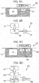
- Fig. 8A schematically illustrating the structure of a unit pixel 700 within a conventional CMOS image sensor having a global shutter function.
- Fig. 8B schematically illustrates the data flow within the unit pixel 700.
- Light received by a photodiode 701 is converted into a charge.
- the charge is transmitted to a floating diffusion 702 at an appropriate timing.
- the potential is amplified by an amplifier 704 in accordance with the amount of charge.
- the light signal is then read out as multi-value information.
- the exposure time is controlled by the timing of resetting the charge at the photodiode 701 and floating diffusion 702, or by the timing of transfer.
- Fig. 8C schematically illustrates the structure of a unit pixel 700 within the vision chip according to the present embodiment.
- Fig. 8D schematically illustrates the data flow within the unit pixel 700.
- the vision chip according to the present embodiment has multiple unit pixels 700.
- Each of the multiple unit pixels 700 typically has a photodiode (PD) 701, a floating diffusion (FD) 702, an extended floating diffusion (EFD) 703, and a comparator 705.
- PD photodiode
- FD floating diffusion
- EFD extended floating diffusion
- the floating diffusion 702 and the extended floating diffusion 703 accumulate the charge generated by the photodiode 701.
- the comparator 705 finds the difference in potential generated in accordance with the charge accumulated in each of the floating diffusion 702 and the extended floating diffusion 703, and compares the relation in magnitude between the two.
- Fig. 9 illustrates an operation sequence of the vision chip according to the present embodiment.
- the charges of the photodiode 701, floating diffusion 702, and extended floating diffusion 703 are each reset at a first point-in-time.
- the charge of the photodiode 701 is transferred to the floating diffusion 702.
- the photodiode 701 is then reset at a third point-in-time.
- the charge of the floating diffusion 702 is transferred to the extended floating diffusion 703 at a fourth point-in-time.
- the charge of the photodiode 701 is transferred to the floating diffusion 702.
- the comparator 705 compares the potential corresponding to the charge of the floating diffusion 702 with the potential corresponding to the charge of the extended floating diffusion 703. As a result of the comparison, a first bit indicating the relation in magnitude between the two, and a second bit indicating whether or not the difference between the two is within a predetermined range, are output.
- the data band of the output of the image sensor will be a bottleneck, leading to increased system cost. Also, in order to find the difference as to past frames, memory to store image data of past frames as it is in multi-value format needs to be provided externally to the image sensor. As a result, memory cost increases in order to secure the memory capacity and bandwidth for accessing the memory.
- output is obtained in which the difference between a first frame exposed between the first point-in-time and the second point-in-time and a second frame exposed between the third point-in-time and the fifth point-in-time is coded.
- the output includes two bits for the two frames for each pixel.
- the vision chip internally holds past frame images as amount of charges, so there is no need to provide external memory, and memory capacity and bandwidth costs can be minimized.
- high-speed measurement of 3000 fps or higher can be realized in three-dimensional measurement of moving objects, and also the time resolution thereof can be maintained at a high level.
- the present disclosure may be suitably applied to the field of machine vision such as FA device control, automobile headlight control, and so forth, interactive projection mapping, and so forth.
- the measurement system and measurement method according to the present disclosure is applicable to medical systems and projection mapping systems, for example
Landscapes
- Engineering & Computer Science (AREA)
- Computer Vision & Pattern Recognition (AREA)
- Physics & Mathematics (AREA)
- General Physics & Mathematics (AREA)
- Length Measuring Devices By Optical Means (AREA)
Abstract
Description
- The present application relates to a measurement system, a measurement method used in the measurement system, and a vision chip.
- A method of acquiring a 3D shape of an object by a structured light has long been known. For example,
PTL 1 discloses such a technology. - PTL 1:
Japanese Unexamined Patent Application Publication No. 60-152903 -
- NPL 1: TAKEI Joji, KAGAMI Shingo, HASHIMOTO Koichi: "Development of a 3,000-fps 3D Imaging Measurement System Using A High-Speed Projector", The Robotics and Mechatronics Conference Proceedings 2007, "1P1-M02(1)" - "1P1-M02(4)", 2007-05-11
- NPL 2: ISHII Idaku, ISHIKAWA Masatoshi: "High Speed Target Tracking Algorithm for 1 ms Visual Feedback System", Journal of the Robotics Society of Japan, vol. 17, No. 2, pp. 195-201 (1999)
- Further improved tracking capabilities of the motion of objects, and further improved robustness, have been demanded with the above-describe conventional measurement systems. One non-limiting and exemplary embodiment of the present disclosure enables improved tracking capabilities of the motion of objects, and further improved robustness.
- Additional benefits and advantages of the embodiment of the disclosure will become apparent from the specification and drawings. The benefits and/or advantages may be individually provided by the various embodiments and features of the specification and drawings, which need not all be provided in order to obtain one or more of such.
- A measurement system according to an aspect of the present disclosure includes: a projection apparatus that projects, onto a subject, first pattern light indicating a first pattern projection image including a first pattern image corresponding to a certain bit in gray code obtained by gray coding projection coordinates stipulated by a projection coordinate system, and a second pattern image having the same cycle as the first pattern image, but having a different phase from the first pattern image, following a projection sequence where projections of the first and second pattern images coexist; and at least one imaging apparatus that images the first pattern light and generates an imaged image.
- These comprehensive or specific embodiments may be implemented as a system, a method, an integrated circuit, a computer program, or a computer-readable storage medium, or any combination of a device, system, method, integrated circuit, computer program, and computer-readable storage medium. Examples of a computer-readable storage medium may include non-volatile recording media, such as a CD-ROM (Compact Disc - Read Only Memory) and so forth.
- According to the present disclosure, tracking capabilities of the motion of objects, and robustness, can be improved.
-
- [
Fig. 1] Fig. 1 is a schematic diagram illustrating a schematic configuration example of ameasurement system 100 according to a first exemplary embodiment. - [
Fig. 2A] Fig. 2A is a diagram illustrating a 5-bit gray code table. - [
Fig. 2B] Fig. 2B is a diagram illustrating a 5-bit auxiliary code corresponding to 5-bit gray code. - [
Fig. 3] Fig. 3 is a conceptual diagram illustrating a part of pattern images corresponding to 5-bit gray code. - [
Fig. 4] Fig. 4 is a schematic functional block diagram of a calculator according to the first exemplary embodiment. - [
Fig. 5] Fig. 5 is a flowchart illustrating a measurement method of the measurement system according to the first exemplary embodiment. - [
Fig. 6A] Fig. 6A is a diagram illustrating a projection sequence in conventional three-dimensional measurement. - [
Fig. 6B] Fig. 6B is a diagram illustrating a projection sequence according to the first exemplary embodiment. - [
Fig. 7] Fig. 7 is a diagram illustrating the way which a projection frame appears when having acquired 0-bit data for X-coordinates. - [
Fig. 8A] Fig. 8A is a schematic diagram illustrating the structure of unit pixels in a conventional CMOS image sensor. - [
Fig. 8B] Fig. 8B is a conceptual diagram schematically illustrating data flow in the unit pixel inFig. 8A . - [
Fig. 8C] Fig. 8C is a schematic diagram illustrating the structure of unit pixels in a vision chip according to a second exemplary embodiment. - [
Fig. 8D] Fig. 8D is a conceptual diagram schematically illustrating data flow in the unit pixel inFig. 8C . - [
Fig. 9] Fig. 9 is a sequence diagram illustrating the operations of the vision chip according to the second exemplary embodiment. - [
Fig. 10] Fig. 10 is a schematic diagram illustrating a schematic configuration example of a conventional measurement system. - Before describing embodiments of the present disclosure, a
conventional measurement system 800 disclosed inPTL 1 will first be described with reference toFig. 10 . - The
measurement system 800 includes animaging apparatus 801, alight source 802, and aslit board 803. Theslit board 803 has slits with different patterns based on various gray codes, such aspatterns imaging apparatus 801 images light corresponding to thepatterns images images image group 805. - According to this configuration, which direction the light from the
light source 802 has been emitted in via theslit board 803 the same light/dark patterns of the three images included in theimage group 805 are based on can be uniquely identified by decoding the gray code. Accordingly, disparity occurring according to the distance to asubject 804 can be identified, and the three-dimensional shape of thesubject 804 can be analogized by triangulation. - Also, besides
PTL 1, in the field of measurement there is known a high-speed 3D shape measurement technique using light pattern projection disclosed inNPL 1. - NPL 1 discloses a technique for high-speed 3D shape measurement technique using light pattern projection. The measurement system in
NPL 1 has an imaging apparatus, a light source, and a projection apparatus including a lens and digital micro-mirror device. The imaging apparatus has a function of performing high-speed photography. For example, the imaging apparatus can perform high-speed photography at 6000 fps. The projection apparatus can project binary patterns having 1024 × 768 pixels at 6000 fps or more. It can be said that a feature thereof in comparison withPTL 1 is the point that the light source and slit board have been replaced with the projection apparatus having the digital micro-mirror device which can be controlled from a calculator at an extremely fast rate. - For example, a pattern obtained by performing Manchester coding of bits obtained by gray coding X-coordinates of a 1024 × 768 image is set in the digital micro-mirror device at 6000 fps. The pattern is projected on a projection object, and the imaging apparatus shoots the projection object upon which the pattern has been projected at 6000 fps.
- The X-coordinate is in a range of 0 to 1023, and accordingly each coordinate is expressed in terms of 10 bits. Further, by performing Manchester coding, each coordinate is expressed in terms of 20 bits. Accordingly, the X coordinates are obtained from 20 frames of imaged images. The distance to the projection object can be obtained for each pixel by triangulation. The results of imaging are transmitted to a calculating apparatus (e.g., a personal computer) and analyzed. New X-coordinate bits can be obtained for recalculation every two frames, by Manchester coding. Accordingly, 3D measurement at resolution of 3000 fps can be realized as the final throughput.
- There is also known the image processing technology regarding high-speed vision space disclosed in
NPL 2. - According to
NPL 2, a high-speed vision space can be defined where the amount of motion of an object between frames is restricted to within 1 pixel within an imaging pixel space, by performing imaging with regard to the system dynamics of an imaging space at a sufficiently fast frame rate, and such an image processing algorithm is created. - Problems of the conventional art that has been considered here will be described.
-
NPL 1 suggests the possibility of realizing three-dimensional measurement of a moving object at a high frame rate, using a projection apparatus and an imaging apparatus. - However, according to the method of
NPL 1, in a case where the projected image of the projection apparatus has 1024 pixels in the X-coordinate direction, for example, 20 frames are used to transmit 10 bits work of X-coordinates. It is true that new three-dimensional measurement results are updated each time a new bit is finalized, so three-dimensional measurement can be performed at a rate of 3000 fps. However, these results include the results before the 20 frames by imaging at the rate of 6000 fps, so the actual time resolution is around 300 fps, which is 1/20 the projection rate. Consequently, the moment speed of a subject which can actually be measured is markedly restricted. - In light of such problems, a measurement system having a new structure, a measurement method and vision chip used therein have been conceived.
- According to the present disclosure, the frame rates of the projection apparatus and imaging apparatus are restricted to be sufficient for the movement speed of a subject to be measured. Thus, a new pattern coding system is provided with improved tracking capabilities of the motion of objects, and further improved robustness. For example, in a case of measuring a human body, even in a case of assuming a subject that is performing an exercise such as in sports or the like, movement exceeding a speed of 30 meters per second is extremely unlikely. If the object of measuring the human body is for medical purposes, the subject speed can be restricted to even lower speeds.
- Also, interactive projection such as projection mapping of amusement facilities and the like is conceivable. Here, in a case of projecting contents synchronized with a ball in a bowling alley, for example, the world record for a ball speed is around 15 meters per second at best. This means that the system will function correctly even if the range of subject speed is restricted according to the usage.
- An overview of an aspect of the present disclosure is as follows.
- A measurement system according to an aspect of the present disclosure includes: a projection apparatus that projects, onto a subject, first pattern light indicating a first pattern projection image including a first pattern image corresponding to a certain bit in gray code obtained by gray coding projection coordinates stipulated by a projection coordinate system, and a second pattern image having the same cycle as the first pattern image, but having a different phase from the first pattern image, following a projection sequence where projections of the first and second pattern images coexist; and at least one imaging apparatus that images the first pattern light and generates an imaged image.
- According to this configuration, a measurement system can be provided which can improve tracking capabilities of the motion of objects and improve robustness.
- In one form, the measurement system may further include a computing device that measures three-dimensional shape information of the subject based on the imaged image.
- According to this configuration, three-dimensional shape information of the subject can be measured in real-time.
- In one form, the projection apparatus may project, upon the subject, second pattern light indicating a second pattern projection image including the first pattern image but not including the second pattern image, for one frame period or more, and thereafter projects the first pattern light on the subject for two frame periods or more. The computing device may measure second three-dimensional shape information indicating absolute distance to the subject, based on the imaged image of the second pattern light projected on the subject that has been imaged by the imaging apparatus, measure first three-dimensional shape information indicating relative amount of change of the subject based on the imaged image of the first pattern light projected on the subject that has been imaged by the imaging apparatus, and update the second three-dimensional shape information based on the first three-dimensional shape information.
- According to this configuration, higher time resolution as compared to conventional techniques can be obtained.
- In one form, the first pattern projection image may further include a third pattern image that differs from the first and second pattern images, and the projection sequence further include projection of the third pattern image. When giving attention to a certain pixel identified by the projection coordinates corresponding among the first, second and third pattern images, the pixel value of the pixel within the third pattern image may be 0 when the pixel value of the pixel is 1 within both the first and second pattern images, and the pixel value of the pixel within the third pattern image may be 1 when the pixel value of the pixel is 0 within both the first and second pattern images.
- According to this configuration, places where pattern light is not being cast can be detected based on the imaging results.
- In one form, in a case where the pixel value of the pixel differs between the first and second pattern images, the pixel value of the pixel within the third pattern image may be a value of 0 or 1 less frequently occurring in past frames of the third pattern image.
- According to this configuration, applicability to two-dimensional image processing can be increased.
- In one form, the computing device may selectively switch mixing of projection of the second pattern image in the projection sequence, in accordance with three-dimensional amount of change of the subject.
- According to this configuration, the speed of the measurement system can be restricted. In the same way, restriction can be applied to acceleration of the moving object as well.
- In one form, the computing device may selectively decide the certain bit in gray code in accordance with three-dimensional amount of change of the subject.
- According to this configuration, the range over which the amount of change of the subject can be tracked can be dynamically changed.
- In one form, the computing device, independently from measurement of the three-dimensional shape of the subject, may search for amount of two-dimensional movement, and decode an image indicating the gray code imaged by the at least one imaging apparatus, referencing the two-dimensional amount of movement.
- According to this configuration, precise three-dimensional measurement can be performed taking into consideration two-dimensional amount of movement.
- In one form, the image used for searching for the two-dimensional amount of movement may be obtained by compositing a plurality of images acquired by the three-dimensional shape measurement.
- According to this configuration, the composited image can be used for two-dimensional image processing such as motion searching, without new photography being performed.
- In one form, the computing device may decode the imaged image, and convert the three-dimensional shape information obtained from the imaging coordinate system into three-dimensional shape information in the projection coordinate system, from the correlation between the decoded projection coordinates and the imaging pixel coordinates stipulated by the imaging coordinate system of the at least one imaging apparatus.
- According to this configuration, three-dimensional shape information in the projection coordinate system can be obtained.
- In one form, the at least one imaging apparatus may be a plurality of imaging apparatuses, the plurality of imaging apparatuses imaging the first pattern light complementing the imaging range of the subject of each other.
- According to this configuration, occlusion regions where pattern light is cast but imaging cannot be performed, can be reduced.
- In one form, the computing device may decode the imaged image, and generate a moiré topography image from the correlation between the decoded projection coordinates and the imaging pixel coordinates stipulated by the imaging coordinate system of the at least one imaging apparatus.
- According to this configuration, a moiré topography image can be obtained as a moving image, and the present disclosure can be suitably applied to the field of medicine.
- In one form, the computing device may generate a projection image based on the three-dimensional shape information, the projection apparatus projecting projection light indicating the projection image on the subject.
- According to this configuration, the present measurement system can be made to function as a projection system.
- According to one form, a vision chip used in the above measurement system includes a plurality of unit pixels. Each of the plurality of unit pixels includes a photoreceptor that receives light and generates charge, a first and second charge accumulating unit that respectively accumulate a first and second charge obtained by the photoreceptor at different points-in-time, and a comparator that compares an amount of the first charge accumulated in the first charge accumulating unit with an amount of the second charge accumulated in the second charge accumulating unit, and generates a first bit indicating the relation in magnitude between the first and second amounts of charge, and a second bit indicating whether or not the difference between the first and second amounts of charge is within a predetermined range, based on the comparison results.
- According to this configuration, there is no need to provide external memory, and memory capacity and band cost can be minimized.
- A measurement method according to an aspect of the present disclosure, used in a measurement system including a projection apparatus and an imaging apparatus, includes: projecting, using the projecting apparatus, onto a subject to be measured, second pattern light indicating a first pattern projection image including a first pattern image corresponding to a certain bit in gray code obtained by gray coding projection coordinates stipulated by a projection coordinate system, and not including a second pattern projection image having the same cycle as the first pattern image, but having a different phase from the first pattern image, for one frame period or more, and thereafter projecting first pattern light indicating a first pattern projection image including the first and second pattern images on the subject for two frame periods or more; measuring second three-dimensional shape information indicating absolute distance to the subject, based on the imaged image of the second pattern light projected on the subject that has been imaged by the imaging apparatus; measuring first three-dimensional shape information indicating relative amount of change of the subject based on the imaged image of the first pattern light projected on the subject that has been imaged by the imaging apparatus; and updating the second three-dimensional shape information based on the first three-dimensional shape information.
- According to this measurement method, tracking capabilities of the motion of objects and robustness can be improved.
- According to the present disclosure, when performing three-dimensional measurement of a moving object using the projection apparatus and imaging apparatus, three-dimensional measurement results can be obtained with higher time resolution as to the frame rate of the projection apparatus, as compared to conventional arrangements.
- A measurement method according to an aspect of the present disclosure includes: a first projection step, where projection, onto a subject, of first data indicating data of a certain bit in gray code obtained by gray coding projection coordinates stipulated by a projection coordinate system, is repeated at a first cycle; a second projection step where projection of second data onto the subject is repeated at the same cycle as the first cycle; and a step of imaging the first data and second data projected into the subject. In the first projection step, a first image is consecutively employed as the first data for a first number of times and thereafter a second image is consecutively employed as the first data for the first number of times, which is repeatedly performed. In the second projection step, a third image is consecutively employed as the second data for the first number of times and thereafter a fourth image is consecutively employed as the second data for the first number of times, which is repeatedly performed.
- Specific embodiments of the present disclosure will be described below with reference to the drawings. Components which are the same or similar in the following description are denoted by the same reference numerals. Redundant description may be omitted. It should be noted that the projection system according to an embodiment of the present disclosure is not restricted to the following exemplary illustrations.
- The structure, functions, and operations of a
measurement system 100 according to the present embodiment will be described with reference toFig. 1 through Fig. 6 . -
Fig. 1 schematically illustrates an example of a schematic configuration of themeasurement system 100. Themeasurement system 100 includes animaging apparatus 101, aprojection apparatus 102, and acalculator 104. - The
projection apparatus 102 projects, on a subject, a first pattern light indicating a first pattern projection image including a first pattern image and a second pattern image, in accordance with a projection sequence where projection of first and second pattern images coexist. The first pattern image is an image corresponding to a particular bit in gray code, obtained by gray coding projection coordinates stipulated by a projection coordinate system. The second pattern image is an image having the same cycle as the first pattern image, but having a different phase from the first pattern image. In the Specification of the Present Application, the term projection coordinate system means a coordinate system that identifies the coordinates of the pixels in the pattern images for projection. Also, coordinates which identify the pixels of the pattern images are called "projection coordinates" of the projection coordinate system. Theprojection apparatus 102 includes a light source, lens optical system, and so forth. - The
projection apparatus 102 has resolution of 32 pixels in the X-axis direction and 28 pixels in the Y-axis direction. Note however, that this resolution is a specification to simplify description. There are known DLP projectors and so forth, for example. a DLP project may have resolution of 1920 pixels in the X-axis direction and 1080 pixels in the Y-axis direction. Binary patterns exceeding 20000 fps can be output using such a DLP projector. A wide range of such products of this type can be used for theprojection apparatus 102. -
Fig. 2A illustrates a 5-bit gray code obtained by gray coding the values of 0 through 31 for the X-coordinates.Fig. 2B illustrates a 5-bit auxiliary code corresponding to 5-bit gray code.Fig. 3 illustrates a part of pattern images corresponding to 5-bit gray code. - The gray code illustrated in
Fig. 2A is obtained by coding 32 types of values by the 5 bits ofbit 0 throughbit 4. Due to the nature of gray code, only one bit changes between adjacent values. - In
Fig. 3 , (X4a) indicates a pattern image corresponding to bit 4 of the X-coordinates gray code value, and (X4b) indicates a pattern image obtained by inverting (X4a). In the same way, (X3a) indicates a pattern image corresponding to bit 3 of the X-coordinates gray code value, and (X2b) indicates a pattern image obtained by inverting (X2a). (X2a) indicates a pattern image corresponding to bit 2 of the X-coordinates gray code value, and (X2b) indicates a pattern image obtained by inverting (X2a). - In
Fig. 3 , (Y4a) indicates a pattern image corresponding to bit 4 of the Y-coordinates gray code value, and (Y4b) indicates a pattern image obtained by inverting (Y4a). In the same way, (Y3a) indicates a pattern image corresponding to bit 3 of the X-coordinates gray code value, and (Y2b) indicates a pattern image obtained by inverting (Y2a). (Y2a) indicates a pattern image corresponding to bit 2 of the Y-coordinates gray code value, and (Y2b) indicates a pattern image obtained by inverting (Y2a). - Although not illustrated, corresponding pattern images and inverted pattern images may exist for
bit - The
projection apparatus 102 sequentially projects these patterns on a subject 103. Theprojection apparatus 102 projects projection light, including projection of images according to the gray code and auxiliary code, following a later-described projection sequence. - The
imaging apparatus 101 sequentially images the projected pattern light, and generates an imaged image. Theimaging apparatus 101 includes an imaging coordinate system which stipulates imaging pixel coordinates. Theimaging apparatus 101 includes an imaging sensor, lens optical system, and so forth. In the Specification of the Present Application, the term imaging coordinate system means a coordinate system that identifies the coordinates of the pixels in the imaged images acquired by theimaging apparatus 101. The coordinates of the pixels of the imaged images are called "imaging coordinates" to distinguish from "projection coordinates" of the imaging coordinate system. - The
calculator 104 has functions of controlling theentire measurement system 100. For example, thecalculator 104 performs measurement of three-dimensional shape information of the subject, based on imaged images. Thecalculator 104 may be realized by a computer, an operation device of which a processor is representative, or by a semiconductor integrated circuit, for example. Examples of semiconductor integrated circuits include ASIC (Application Specific Integrated Circuit) and FPGA (Field Programmable Gate Array), for example. A computer program which exhibits the functions of the components may be loaded in the memory, with the functions of the components being realized by a processor within the semiconductor integrated circuit successively executing the computer program. - Details of the structure and functions of the
calculator 104 will be described with reference toFig. 4 . -
Fig. 4 illustrates an example of a functional block configuration of thecalculator 104. Thecalculator 104 includes animage output unit 400, animage input unit 410, adifference calculation unit 420, aframe memory unit 430, acode decoding unit 440, a coordinateconversion unit 450, a coordinateconversion memory unit 460, a coordinateinterpolation unit 470,content generating unit 480, apattern generating unit 490, and theimage output unit 400. The memory units in thecalculator 104 may be configured including RAM or the like, for example. Note that the coordinateconversion unit 450, coordinateconversion memory unit 460, coordinateinterpolation unit 470, andcontent generating unit 480 may be optionally provided. Themeasurement system 100 may function as a projection system, which will be described later. The functions which these functional blocks have can be implemented in thecalculator 104 when functioning as a projection system. - The
image input unit 410 receives imaged images (image data) imaged by theimaging apparatus 101, synchronously with theimage output unit 400. Theimage input unit 410 transmits the received image data to thedifference calculation unit 420. - The
difference calculation unit 420 calculates the difference in pattern images representing inverted bits and non-inverted bits for each bit of the gray code, thereby decoding the Manchester code, and outputs data to thecode decoding unit 440 every two frames. - Specifically, if the imaged data received from the
image input unit 410 is an X and Y coordinate non-bit-inverted image, thedifference calculation unit 420 writes the image data to theframe memory unit 430. If the imaged data is an X and Y coordinate bit-inverted image, thedifference calculation unit 420 reads to the non-bit-inverted image written to theframe memory unit 430 before, and finds the difference between the two. By finding the difference, the "0"s and "1"s of the projection light can be distinguished without dependency on the color of the subject or the ambient light. A region where the difference is a predetermined value or lower is determined as being a region where no projection light has been projected, and that region can be eliminated from being a region which is the object of measurement. - A code
decoding memory unit 441 is provided with a write region for each pixel of theimaging apparatus 101. The bit values of the coordinate data that has been gray coded is written to that write region in increments of bits. This operation is sequentially executed during the exposure time of theimaging apparatus 101. - The
code decoding unit 440 reads out the data recorded in the codedecoding memory unit 441 in increments of bits. Thecode decoding unit 440 updates a certain bit in accordance with information indicating the type of pattern currently being output by the pattern generating unit 490 (pattern type information), and writes the updated data in increments of bits to the aforementioned write region within the codedecoding memory unit 441. - Upon having received imaging data based on the second pattern light indicating the second pattern projection image, the
code decoding unit 440 decodes the imaging data and generates second three-dimensional shape information representing the relative distance information to the subject. Upon having received imaging data based on the first pattern light indicating the first pattern projection image, thecode decoding unit 440 decodes that image data, and generates first three-dimensional shape information representing relative amount of change of the subject. At this time, thecode decoding unit 440 corrects (updates) the absolute distance information to the subject based on the amount of change. That is to say, thecode decoding unit 440 updates the second three-dimensional shape information based on the first three-dimensional shape information. - The
code decoding unit 440 finally reconverts the gray code coordinate data recorded in the codedecoding memory unit 441 into binary, and outputs to the coordinateconversion unit 450. - Due to the processing so far, it can be found which pixel of the
projection apparatus 102 that projection light, imaged at a certain pixel of theimaging apparatus 101, has been projected from. That is to say, the correlation between projection coordinates and imaging coordinates can be known. Accordingly, once the relative positional relationship between theimaging apparatus 101 and theprojection apparatus 102 is known, the distance to the subject can be found by triangulation for each imaged pixel. However, the obtained information is distance information corresponding to the imaging pixels of theimaging apparatus 101 accordingly, that information is converted into distance information corresponding to the pixel coordinates of theprojection apparatus 102 in the present embodiment. - The coordinate
conversion unit 450 writes the data received from thecode decoding unit 440 into a region of the coordinateconversion memory unit 460 identified by an address corresponding to the projection coordinates of theprojection apparatus 102. Thereafter, the coordinateconversion unit 450 reads out the second three-dimensional shape information from the coordinateconversion memory unit 460, in order of X-coordinates and Y-coordinates of theprojection apparatus 102, thereby generating distance information to the subject corresponding to the projection coordinates of theprojection apparatus 102. - At that time, there may be a projection pixel generated which does not have a corresponding point. Specifically, of the pattern images projected on the subject, each light corresponding to a certain plurality of pixels can be imaged by one imaging pixel of the
imaging apparatus 101. In this case, the projection pixels with no corresponding points are included on the pixel coordinates of one of the two adjacent projection pixels, due to the nature of gray code, so one projection pixel is in a state of having no correlating destination. - The coordinate
interpolation unit 470 receives distance information corresponding to the projection coordinates of theprojection apparatus 102, from the coordinateconversion unit 450. The coordinateinterpolation unit 470 interpolates distance information regarding projection coordinates having no distance information. This is limited to portions where there are a certain number of projection coordinates having distance information which can be interpolated present in the perimeter thereof, and is performed using an interpolation technique such as linear interpolation or the like, from the distance information of the peripheral coordinates. The coordinateinterpolation unit 470 outputs the distance information from the projection coordinate system to thecontent generating unit 480. - The
content generating unit 480 generates video content for projection. Thecontent generating unit 480 processes video content recording beforehand based on the distance information received from the coordinateinterpolation unit 470, and outputs the processed video content to theimage output unit 400. The processed video content may be referred to as "post-processing video content", to distinguish from the video content before processing that has been recorded beforehand. - The
content generating unit 480 generates video content accurately corresponding to the distance to the subject, without any coordinate deviation. Thecontent generating unit 480 outputs the post-processing video content for projection to theimage output unit 400. - The
pattern generating unit 490 has a basicpattern generating unit 491, an auxiliarypattern generating unit 492, and aselector 493. The basicpattern generating unit 491 generates a basic pattern indicating gray code obtained by gray coding the projection coordinates stipulated by the projection coordinate system. The first image pattern is included in the basic pattern. The auxiliarypattern generating unit 492 generates an auxiliary pattern having the same cycle as the basic pattern, but having a different phase from the basic pattern. The second image pattern is included in the auxiliary pattern. - A basic pattern or auxiliary pattern is selected by the
selector 493, and output to theimage output unit 400. The auxiliary pattern and basic pattern are selectively intermingled by switching of theselector 493 in accordance with the three-dimensional amount of change of the subject 103. As a result, a projection sequence where projection of basic patterns and auxiliary patterns coexist is decided. - The
image output unit 400 outputs video content generated by thecontent generating unit 480, and projection patterns including basic patterns and auxiliary patterns, generated by thepattern generating unit 490, to theprojection apparatus 102. Theprojection apparatus 102 projects projection light indicating the post-processing video content on the subject 103. - Operations of the
measurement system 100 will be describe with reference toFig. 5 ,Fig. 6A , andFig. 6B . -
Fig. 5 is a flowchart of the measurement method of themeasurement system 100. - First, an example of an initial calibration method of the
measurement system 100 will be described. In the initial calibration, theprojection apparatus 102 projects second pattern light, indicating a second pattern projection image that includes a first pattern image does not include a second pattern image, on the subject for a period of 1 frame or longer. - In the initial calibration, a non-moving object or the like that has a reference plane is set at the position of the subject 103. The
projection apparatus 102 projects pattern light indicating the pattern image (X4a) inFig. 3 on the subject 103. Theimaging apparatus 101 then images this pattern light, and acquires a first calibration image. - Next, the
projection apparatus 102 projects pattern light indicating the pattern image (X4b) inFig. 3 on the object. Theimaging apparatus 101 then images this pattern light, and acquires a second calibration image. - By comparing the first calibration image and the second calibration image, a region where difference is small can be determined to be a region where no projection light has been cast. On the other hand, a region where difference is great can be determined to be a region where projection light has been cast, and projection coordinates can be decoded from the code of this difference.
- By repeating the above-described processing on all 5 bits of each of the X coordinate and Y coordinate, it can be known from which pixel of the
projection apparatus 102 that the projection light, imaged at a certain pixel of theimaging apparatus 101, has been projected. That is to say, the correlation between the projection coordinates and the imaging coordinates stipulated by the imaging coordinates system of the imaging apparatus can be known. Finally, absolute distance information to the reference plane (second three-dimensional shape information) is obtained by thecalculator 104. - In later-described 3D measurement, the difference in the X axial direction as to the reference plane is converted into distance by triangulation. Y-axis directional setup error, lens distortion, and so forth, may be obtained beforehand in the initial calibration. Of course, in a case where measurement precision is not necessary, it is needless to say that the initial calibration is unnecessary.
- The
projection apparatus 102 projects the first pattern light, indicating the first pattern projection image including the first pattern image and second pattern image, on the subject for a period of 2 frames or longer. In other words, theprojection apparatus 102 projects pattern light on the subject following a projection sequence with image projection corresponding to basic patterns and auxiliary patterns coexisting. At this time, theprojection apparatus 102 projects pattern images of each of non-inverted bits and inverted bits. - The
imaging apparatus 101 images the first pattern light. Thecalculator 104 acquires the first three-dimensional shape information from the imaged image based on the first pattern light. - Thereafter, the
calculator 104 updates the second three-dimensional shape information based on the first three-dimensional shape information. Accordingly, a moving object can be tracked based on relative amount of change. - Next, the measurement method of a moving object according to the present embodiment will be described while comparing with the conventional method.
-
Fig. 6A illustrates a projection sequence in conventional three-dimensional measurement. The conventional projection sequence performs measurement while sequentially projecting projection light forbit 0 throughbit 5 for X-coordinates, Two frames including the inverted pattern image are used in measurement of 1 bit, so in the example illustrated inFig. 6A , measurement is performed in 10-frame cycles. - In a conventional projection sequence, the past 5 bits worth is tabulated and X coordinates are acquired, each time measurement results of a new bit are acquired. Thus, the distance to the subject 103 can be obtained by triangulation. However, this is dependent on images of the past 10 frames, so deterioration in time resolution is unavoidable.
- In the present embodiment, a certain bit in auxiliary code is used in addition to the gray code illustrated in
Fig. 6A that is used in conventional measurement. - Referencing
Figs. 2A and2B again, with particular notice given to the code columns of each bit in the gray code and auxiliary code illustrated respectively inFigs. 2A and2B , it can be seen that the cycle of repetitive patterns of 0s and 1s according to the bit position is the same between the gray code and auxiliary code, with the phase of repetitive patterns being shifted 90 degrees from each other. That is to say, the auxiliary code is obtained by shifting the phase of the gray code by 90 degrees for each bit. - The present embodiment assumes that the distance of object of measurement does not change one pixel worth or more in a section for measuring 3 bits, i.e., in 6 frame sections. Hereinafter, a measurement method of using
bit 0 in auxiliary code corresponding tobit 0 in gray code. -
Fig. 6B illustrates a projection sequence in the three-dimensional measurement according to the present embodiment. - The imaging sequence according to the present embodiment has increment sequences determined by sections of measuring 3 bits. An increment sequence includes
bit 0 of the gray code andbit 0 of the auxiliary code corresponding thereto. The increment sequence also includes bits other thanbit 0 of the gray code. In the illustrated example, first, pattern light indicating an image corresponding to bit 0 of the gray code,bit 0 of the auxiliary code, andbit 1 of the gray code, is projected in this order. Next, pattern light indicating an image corresponding to bit 0 of gray code,bit 0 of auxiliary code,bit 2 of gray code,bit 0 of gray code,bit 0 of auxiliary code,bit 3 of gray code,bit 0 of gray code,bit 0 of auxiliary code, andbit 4 of gray code, is projected in this order. Accordingly, 24 frames are required for all bits to be included. Thereafter, such projection is repeatedly executed. Thus, auxiliary code is inserted between gray code in the projection sequence according to the present embodiment. - However, observing
bit 0 in the gray code inFig. 2A andbit 0 in the auxiliary code inFig. 2B , it can be seen that as long as the change in distance to the subject is smaller than 1 pixel, relative change in the distance of the subject can be tracked by monitoringbit 0 in the gray code and auxiliary code. This measurement method is known as a technique for measuring relative movement amount by a rotary encoder or the like using gray code. - According to the present embodiment, the absolute value of distance to a subject first appearing in a frame is obtained with a delay of 24 frames. Thereafter, the relative value of change in distance can be obtained every 6 frames. Accordingly, the charge in distance to a subject regarding which the absolute value has been once captured can be tracked using 6 frames. Thus, high time resolution can be obtained as compared to conventional techniques.
- While an example of using
bit 0 of the auxiliary code has been illustrated in the present embodiment, the present disclosure is not restricted to this.Bit 1 orbit 2 or the like may be used for tracking relative amount of movement, in accordance with the amount of moment of the moving object to be measured. A certain bit of gray code may be made to be selectably decidable in accordance with the three-dimensional amount of change of the subject. For example, usingbit 1 of the auxiliary code enables a moving object changing within a range of 3 pixels to be tracked, as illustrated inFig. 2B . Also, usingbit 2 of the auxiliary code enables a moving object changing within a range of 7 pixels to be tracked. - Also, mixing projection of auxiliary pattern images in the projection sequence while measuring the movement speed of the subject, i.e., whether or not to use auxiliary patterns, can be selectively switched in accordance to the three-dimensional amount of change of the subject. Further, the position of the bit in the auxiliary pattern that use used may be dynamically changed. Many systems can actually restrict their own speed. In the same way, the acceleration of the moving object by also be subject to restriction. Change in speed does not occur beyond a certain level, so the subject can be tracked within a certain range even if the bit in the auxiliary pattern is dynamically changed.
- Also, a greater number of pattern images can be superimposed in one frame period by changing the color or wavelength for each pattern image, instead of projecting pattern light indicating pattern images in increments of frames.
- Hereinafter, description will be made primarily by way of a modification of the present embodiment.
- The
measurement system 100 according to the present embodiment has oneimaging apparatus 101. However, themeasurement system 100 may be provided withmultiple imaging apparatuses 101. Themultiple imaging apparatuses 101 can image pattern light so as to compensate for each others' imaging range of the subject 103. Accordingly, occlusion regions where projection light is cast but imaging cannot be performed, can be reduced. - Disposing at least two
imaging apparatuses 101 on both sides of theprojection apparatus 102 enables occlusion regions, where projection light is cast but imaging cannot be performed, to be reduced. - Although attention has been given to change in the distance direction (Z direction) between the
projection apparatus 102 and the subject 103 in the present invention, it is needless to say that the subject 103 may change in the X-Y coordinate directions on the imaging plane, as well. - The
calculator 104 may, independently from three-dimensional shape measurement of the subject, search for the amount of two-dimensional movement, and decode an image indicating gray code imaged by theimaging apparatus 101, referencing the amount of two-dimensional movement. - Movement searching by two-dimensional image processing has been conventionally known as a method to track change in the X-Y coordinate directions. Obtaining motion vectors of the pixels by conventional movement searching, and decoding gray code based corresponding pixel positions in pas frames, enables an even higher level of measurement to be obtained. In particular, the amount of movement of the subject can be restricted to within one pixel in high-speed vision space, so even if searching is performed in all directions, the range of the search is no larger than within a 3 x 3 range.
- In a case where the frame rate becomes 1/10, a range of 21 x 21 needs to be searched. This requires 49 times the amount of computations as compared to searching a 3 x 3 range ten times. Thus, there can be cases where the frame rate is increased and the amount of data is increased tenfold, but the amount of computations contrarily decreases to 1/49. This is a feature of image processing with restrictions applied to high-speed vision space.
- Now, a method will be proposed to obtaining an image to be handled in two-dimensional image processing, by compositing an imaged image of a non-inverted-bit pattern for projection, such as gray code or an auxiliary pattern or the like, and an imaged image of the inverted-bit pattern thereof.
- Using images of non-inverted-bit patterns and inverted-bit patterns is the technique described in
NPL 1 to improve robustness by Manchester coding. In Manchester coding, the frequency of occurrence of 0s and 1s in the temporal direction is equal at each bit. Accordingly, compositing multiple measurement images yields images equivalent to images obtained in a state where a constant amount of light is projected to all pixels. Thus, the composited image can be used for two-dimensional image processing such as movement searching and so forth, without having to perform new photography. - Further, a method of using other than inverted-bit pattern images will be proposed as an extension of coding.
- The four frames of an image corresponding to
bit 0 in gray code, the inverted image thereof, an image corresponding tobit 0 in auxiliary pattern, and the inverted image thereof, are used in the above description. In the same way, measurement of a moving object can be realized using three frames, as well. In this method, the projection sequence further includes projection of a third image frame. -
Fig. 7 illustrates the way a projection frame appears when acquiring 0 bit data of X-coordinates. InFig. 7 , the term first image frame means a frame of an image corresponding to bit 0 of the gray code inFig. 2A . The term second image frame means a frame of an image corresponding to bit 0 of the auxiliary pattern inFig. 2B . In the third image frame, at each pixel, the pixel value of the pixel corresponding to that pixel is 0 when the pixel value of the pixel is 1 within both the first and second image frames, and the pixel value of the pixel corresponding to that pixel is 1 when the pixel value of the pixel is 0 within both the first and second image frames. Note that in the third image frame, pixel values of pixels where the pixel values of both the first and second image frames differ can be handled as a don't-care value. These image frames may be projected in random order. - According to this method, if the movement of the object of measurement is sufficiently small in the three frame periods, each pixel will include 0 and 1, so a place where projection light is not being cast can be detected based on the imaging results. 0/1 determination can be made at places where projection light is being cast.
- Further, in a case where, of the pixels in the third image frame, the pixel values of the pixels corresponding to that pixel differ between the first image frame and the second image frame, a value of 0 or 1 less frequently occurring in past frames of the third image frame may be allocated to the pixel within the third image frame.
- Accordingly, the frequency of occurrence of 0s and 1 s can be made uniform at each pixel, whereby applicability to the above-described two-dimensional image processing can be further improved. Also, flickering of patterns, which can occur in cases of using visible light to perform measurement, can be reduced. Further, in the projection apparatus, burn-in of the liquid crystal can be prevented, and lower life span due to deviation of the micro-mirror device can be prevented.
- The
projection apparatus 102 is used for measurement in the present disclosure, so thesame projection apparatus 102 can be applied to fields such as projection mapping and so forth. Particularly, the measurement results can be converted into projection coordinates of theprojection apparatus 102 since a correlation between the imaging coordinates of theprojection apparatus 102 and the projection coordinates of theimaging apparatus 101 is obtained as a characteristic of measurement according to the present disclosure. This correlation being obtained means that various contents can be generated using this information, one example thereof being generating moire topography images from that relationship. In this case, thecontent generating unit 480 within thecalculator 104 generates moire topography images as video content. Of course, conventional applications using distance information such as 3D computer graphics and so forth may be made as well. Note however, that conventional depth sensors that simply acquire distance information fundamentally cannot generate an exact moiré topography image, so this can be said to be a useful expression format that can be carried out by this method. - Moiré topography is a technology that uses slits at both the light projection and imaging to image contour lines of the subject. The correlation of imaging coordinates and projection coordinates has been obtained in the present embodiment, so moiré topography images can be obtained as a moving image by assuming slits for each and performing recalculation. Further, recording the original data for moiré topography images in memory or the like enables images with changed slit intervals to be obtained at a later time.
- There are many users accustomed to seeing moiré topography images in the field of medicine, so being able to convert the image format is extremely meaningful. Further, applying projection mapping as described above enables an image indicating an affected part to be projected on the actual human body.
- A vision chip according to the present embodiment will be described with reference to
Fig. 8A through Fig. 8D . the vision chip according to the present embodiment can be used in themeasurement system 100 according to the first embodiment. -
Fig. 8A schematically illustrating the structure of aunit pixel 700 within a conventional CMOS image sensor having a global shutter function.Fig. 8B schematically illustrates the data flow within theunit pixel 700. - Light received by a
photodiode 701 is converted into a charge. The charge is transmitted to a floatingdiffusion 702 at an appropriate timing. Thereafter, the potential is amplified by anamplifier 704 in accordance with the amount of charge. The light signal is then read out as multi-value information. The exposure time is controlled by the timing of resetting the charge at thephotodiode 701 and floatingdiffusion 702, or by the timing of transfer. -
Fig. 8C schematically illustrates the structure of aunit pixel 700 within the vision chip according to the present embodiment.Fig. 8D schematically illustrates the data flow within theunit pixel 700. - The vision chip according to the present embodiment has
multiple unit pixels 700. Each of themultiple unit pixels 700 typically has a photodiode (PD) 701, a floating diffusion (FD) 702, an extended floating diffusion (EFD) 703, and acomparator 705. - The floating
diffusion 702 and the extended floatingdiffusion 703 accumulate the charge generated by thephotodiode 701. Thecomparator 705 finds the difference in potential generated in accordance with the charge accumulated in each of the floatingdiffusion 702 and the extended floatingdiffusion 703, and compares the relation in magnitude between the two. - An operation sequence of the vision chip according to the present embodiment will be described with reference to
Fig. 9 . -
Fig. 9 illustrates an operation sequence of the vision chip according to the present embodiment. - First, the charges of the
photodiode 701, floatingdiffusion 702, and extended floatingdiffusion 703 are each reset at a first point-in-time. - Next, at a second point-in-time, the charge of the
photodiode 701 is transferred to the floatingdiffusion 702. - The
photodiode 701 is then reset at a third point-in-time. - Next, the charge of the floating
diffusion 702 is transferred to the extended floatingdiffusion 703 at a fourth point-in-time. - Then at a fifth point-in-time, the charge of the
photodiode 701 is transferred to the floatingdiffusion 702. - Finally, the
comparator 705 compares the potential corresponding to the charge of the floatingdiffusion 702 with the potential corresponding to the charge of the extended floatingdiffusion 703. As a result of the comparison, a first bit indicating the relation in magnitude between the two, and a second bit indicating whether or not the difference between the two is within a predetermined range, are output. - If a conventional image sensor is applied to the measurement system according to the first embodiment, the data band of the output of the image sensor will be a bottleneck, leading to increased system cost. Also, in order to find the difference as to past frames, memory to store image data of past frames as it is in multi-value format needs to be provided externally to the image sensor. As a result, memory cost increases in order to secure the memory capacity and bandwidth for accessing the memory.
- According to the vision chip of the present embodiment, output is obtained in which the difference between a first frame exposed between the first point-in-time and the second point-in-time and a second frame exposed between the third point-in-time and the fifth point-in-time is coded. The output includes two bits for the two frames for each pixel.
- The vision chip internally holds past frame images as amount of charges, so there is no need to provide external memory, and memory capacity and bandwidth costs can be minimized.
- According to the measurement system of the present disclosure, high-speed measurement of 3000 fps or higher can be realized in three-dimensional measurement of moving objects, and also the time resolution thereof can be maintained at a high level.
- The following is a description of examples of assumed applications of the present disclosure.
- The present disclosure may be suitably applied to the field of machine vision such as FA device control, automobile headlight control, and so forth, interactive projection mapping, and so forth. Application to measurement fields of measuring quick human movements such as in sports or the like, and to the medical field, is conceivable. There are formats such as moiré topography in the field of medicine with which many are accustomed to using, and as described above, the imaging data according to the present disclosure can be converted into moire topography format images.
- The measurement system and measurement method according to the present disclosure is applicable to medical systems and projection mapping systems, for example
-
- 100, 800
- measurement system
- 101, 801
- imaging apparatus
- 102
- projection apparatus
- 103, 804
- subject
- 104
- calculator
- 400
- image output unit
- 410
- image input unit
- 420
- difference calculation unit
- 430
- frame memory unit
- 440
- code decoding unit
- 441
- code decoding memory unit
- 450
- coordinate conversion unit
- 460
- coordinate conversion memory unit
- 470
- coordinate interpolation unit
- 480
- content generating unit
- 490
- pattern generating unit
- 491
- basic pattern generating unit
- 492
- auxiliary pattern generating unit
- 493
- selector
- 410
- image output unit
- 411
- pattern generating unit
- 701
- photodiode
- 702
- floating diffusion
- 703
- extended floating diffusion
- 704
- amplifier
- 705
- comparator
- 802
- light source
- 803
- slit board
- 805
- image group
Claims (16)
- A measurement system comprising:a projection apparatus that projects, onto a subject, first pattern light indicating a first pattern projection image including a first pattern image corresponding to a certain bit in gray code obtained by gray coding projection coordinates stipulated by a projection coordinate system, and a second pattern image having the same cycle as the first pattern image, but having a different phase from the first pattern image, following a projection sequence where projections of the first and second pattern images coexist; andat least one imaging apparatus that images the first pattern light and generates an imaged image.
- The measurement system according to Claim 1, further comprising:a computing device that measures three-dimensional shape information of the subject based on the imaged image.
- The measurement system according to Claim 2,
wherein the projection apparatus projects, upon the subject, second pattern light indicating a second pattern projection image including the first pattern image but not including the second pattern image, for one frame period or more, and thereafter projects the first pattern light on the subject for two frame periods or more,
and wherein the computing device measures second three-dimensional shape information indicating absolute distance to the subject, based on the imaged image of the second pattern light projected on the subject that has been imaged by the imaging apparatus, measures first three-dimensional shape information indicating relative amount of change of the subject based on the imaged image of the first pattern light projected on the subject that has been imaged by the imaging apparatus, and updates the second three-dimensional shape information based on the first three-dimensional shape information. - The measurement system according to Claim 3,
wherein the first pattern projection image further includes a third pattern image that differs from the first and second pattern images,
wherein the projection sequence further includes projection of the third pattern image,
and wherein, when giving attention to a certain pixel identified by the projection coordinates corresponding among the first, second and third pattern images, the pixel value of the pixel within the third pattern image is 0 when the pixel value of the pixel is 1 within both the first and second pattern images, and the pixel value of the pixel within the third pattern image is 1 when the pixel value of the pixel is 0 within both the first and second pattern images. - The measurement system according to Claim 4,
wherein, in a case where the pixel value of the pixel differs between the first and second pattern images, the pixel value of the pixel within the third pattern image is a value of 0 or 1 less frequently occurring in past frames of the third pattern image. - The measurement system according to Claim 2,
wherein the computing device selectively switches mixing of projection of the second pattern image in the projection sequence, in accordance with three-dimensional amount of change of the subject. - The measurement system according to Claim 2,
wherein the computing device selectively decides the certain bit in gray code in accordance with three-dimensional amount of change of the subject. - The measurement system according to Claim 2,
wherein the computing device, independently from measurement of the three-dimensional shape of the subject, searches for amount of two-dimensional movement, and decodes an image indicating the gray code imaged by the at least one imaging apparatus, referencing the two-dimensional amount of movement. - The measurement system according to Claim 2,
wherein the image used for searching for the two-dimensional amount of movement is obtained by compositing a plurality of images acquired by the three-dimensional shape measurement. - The measurement system according to Claim 2,
wherein the computing device decodes the imaged image, and converts the three-dimensional shape information obtained from the imaging coordinate system into three-dimensional shape information in the projection coordinate system, from the correlation between the decoded projection coordinates and the imaging pixel coordinates stipulated by the imaging coordinate system of the at least one imaging apparatus. - The measurement system according to Claim 1,
wherein the at least one imaging apparatus is a plurality of imaging apparatuses,
and wherein the plurality of imaging apparatuses image the first pattern light complementing the imaging range of the subject of each other. - The measurement system according to Claim 2,
wherein the computing device decodes the imaged image, and generates a moire topography image from the correlation between the decoded projection coordinates and the imaging pixel coordinates stipulated by the imaging coordinate system of the at least one imaging apparatus. - The measurement system according to Claim 2,
wherein the computing device generates a projection image based on the three-dimensional shape information,
and wherein the projection apparatus projects projection light indicating the projection image on the subject. - A vision chip used in the measurement system according to Claim 1, including a plurality of unit pixels,
wherein each of the plurality of unit pixels includesa photoreceptor that receives light and generates charge,a first and second charge accumulating unit that respectively accumulate a first and second charge obtained by the photoreceptor at different points-in-time, anda comparator that compares an amount of the first charge accumulated in the first charge accumulating unit with an amount of the second charge accumulated in the second charge accumulating unit, and generates a first bit indicating the relation in magnitude between the first and second amounts of charge, and a second bit indicating whether or not the difference between the first and second amounts of charge is within a predetermined range, based on the comparison results. - A measurement method used in a measurement system including a projection apparatus and an imaging apparatus, the method comprising:projecting, using the projecting apparatus, onto a subject to be measured, second pattern light indicating a first pattern projection image including a first pattern image corresponding to a certain bit in gray code obtained by gray coding projection coordinates stipulated by a projection coordinate system, and not including a second pattern projection image having the same cycle as the first pattern image, but having a different phase from the first pattern image, for one frame period or more, and thereafter projecting first pattern light indicating a first pattern projection image including the first and second pattern images on the subject for two frame periods or more;measuring second three-dimensional shape information indicating absolute distance to the subject, based on the imaged image of the second pattern light projected on the subject that has been imaged by the imaging apparatus;measuring first three-dimensional shape information indicating relative amount of change of the subject based on the imaged image of the first pattern light projected on the subject that has been imaged by the imaging apparatus; andupdating the second three-dimensional shape information based on the first three-dimensional shape information.
- A measurement method comprising:a first projection step, where projection, onto a subject, of first data indicating data of a certain bit in gray code obtained by gray coding projection coordinates stipulated by a projection coordinate system, is repeated at a first cycle;a second projection step where projection of second data onto the subject is repeated at the same cycle as the first cycle; anda step of imaging the first data and second data projected into the subject;wherein, in the first projection step, a first image is consecutively employed as the first data for a first number of times and thereafter a second image is consecutively employed as the first data for the first number of times, which is repeatedly performed,and wherein, in the second projection step, a third image is consecutively employed as the second data for the first number of times and thereafter a fourth image is consecutively employed as the second data for the first number of times, which is repeatedly performed.
Applications Claiming Priority (3)
| Application Number | Priority Date | Filing Date | Title |
|---|---|---|---|
| JP2014043467 | 2014-03-06 | ||
| JP2014240115A JP6434788B2 (en) | 2014-03-06 | 2014-11-27 | Measuring system, measuring method and vision chip |
| PCT/JP2015/000272 WO2015133053A1 (en) | 2014-03-06 | 2015-01-22 | Measurement system, measurement method, and vision chip |
Publications (3)
| Publication Number | Publication Date |
|---|---|
| EP3115743A1 true EP3115743A1 (en) | 2017-01-11 |
| EP3115743A4 EP3115743A4 (en) | 2017-04-12 |
| EP3115743B1 EP3115743B1 (en) | 2018-09-19 |
Family
ID=54054875
Family Applications (1)
| Application Number | Title | Priority Date | Filing Date |
|---|---|---|---|
| EP15758032.5A Active EP3115743B1 (en) | 2014-03-06 | 2015-01-22 | Measurement system, measurement method, and vision chip |
Country Status (6)
| Country | Link |
|---|---|
| US (1) | US10240915B2 (en) |
| EP (1) | EP3115743B1 (en) |
| JP (1) | JP6434788B2 (en) |
| KR (1) | KR102217934B1 (en) |
| CN (1) | CN106062507B (en) |
| WO (1) | WO2015133053A1 (en) |
Families Citing this family (14)
| Publication number | Priority date | Publication date | Assignee | Title |
|---|---|---|---|---|
| US10032279B2 (en) * | 2015-02-23 | 2018-07-24 | Canon Kabushiki Kaisha | Information processing apparatus, information processing method, and storage medium |
| US10168146B2 (en) * | 2015-05-29 | 2019-01-01 | Canon Kabushiki Kaisha | Measuring shape of specular objects by local projection of coded patterns |
| GB2548827B (en) * | 2016-03-25 | 2020-09-23 | Jaguar Land Rover Ltd | Apparatus, system, method and computer program for providing lighting of a vehicle |
| JP6153050B1 (en) | 2016-06-08 | 2017-06-28 | パナソニックIpマネジメント株式会社 | Projection system |
| EP3273681B1 (en) | 2016-06-08 | 2020-06-17 | Panasonic Intellectual Property Management Co., Ltd. | Projection system |
| JP2019114884A (en) * | 2017-12-22 | 2019-07-11 | セイコーエプソン株式会社 | Detector, display device, detection method |
| JP6880512B2 (en) * | 2018-02-14 | 2021-06-02 | オムロン株式会社 | 3D measuring device, 3D measuring method and 3D measuring program |
| CN108776338B (en) * | 2018-06-19 | 2022-05-24 | 四川大学 | Signal source space sensing method and device and active sensing system |
| JP7130544B2 (en) | 2018-12-20 | 2022-09-05 | 三星電子株式会社 | 3D information calculation device, 3D measurement device, 3D information calculation method, and 3D information calculation program |
| TWI680648B (en) * | 2018-12-26 | 2019-12-21 | 財團法人工業技術研究院 | Code disk, optical detector, optical absolute rotary encoder and method for outputting, error detecting and correcting code values |
| CN112051587B (en) * | 2019-06-07 | 2025-05-16 | 松下知识产权经营株式会社 | Subject position detection system and position detection method |
| JP7184072B2 (en) * | 2020-10-23 | 2022-12-06 | セイコーエプソン株式会社 | IDENTIFICATION METHOD, IDENTIFICATION SYSTEM AND PROGRAM |
| CN117795287A (en) * | 2021-08-13 | 2024-03-29 | 国立大学法人东京大学 | Information processing device, computer program and pattern code |
| CN114363600B (en) * | 2022-03-15 | 2022-06-21 | 视田科技(天津)有限公司 | Remote rapid 3D projection method and system based on structured light scanning |
Family Cites Families (28)
| Publication number | Priority date | Publication date | Assignee | Title |
|---|---|---|---|---|
| JPS5593008A (en) * | 1979-01-09 | 1980-07-15 | Canon Inc | Signal formation unit |
| JPS60152903A (en) | 1984-01-21 | 1985-08-12 | Kosuke Sato | Position measuring method |
| DE4007502A1 (en) * | 1990-03-09 | 1991-09-12 | Zeiss Carl Fa | METHOD AND DEVICE FOR CONTACTLESS MEASUREMENT OF OBJECT SURFACES |
| EP0662600A4 (en) * | 1993-06-10 | 1997-02-12 | Oh Yoh Keisoku Kenkyusho Kk | Apparatus for measuring position of moving object. |
| JP3218889B2 (en) * | 1994-09-30 | 2001-10-15 | スズキ株式会社 | Three-dimensional object shape inspection device |
| JP3525964B2 (en) * | 1995-07-05 | 2004-05-10 | 株式会社エフ・エフ・シー | 3D shape measurement method for objects |
| US6438272B1 (en) * | 1997-12-31 | 2002-08-20 | The Research Foundation Of State University Of Ny | Method and apparatus for three dimensional surface contouring using a digital video projection system |
| US6377353B1 (en) * | 2000-03-07 | 2002-04-23 | Pheno Imaging, Inc. | Three-dimensional measuring system for animals using structured light |
| US6634552B2 (en) * | 2001-09-26 | 2003-10-21 | Nec Laboratories America, Inc. | Three dimensional vision device and method, and structured light bar-code patterns for use in the same |
| JP2003270719A (en) * | 2002-03-13 | 2003-09-25 | Osaka Industrial Promotion Organization | Projection method, projection device, work support method, and work support system |
| US7570368B2 (en) * | 2004-05-12 | 2009-08-04 | Veeco Instruments Inc. | Method and apparatus for measuring the curvature of reflective surfaces |
| JP4883517B2 (en) * | 2004-11-19 | 2012-02-22 | 学校法人福岡工業大学 | Three-dimensional measuring apparatus, three-dimensional measuring method, and three-dimensional measuring program |
| JP4670341B2 (en) * | 2004-12-22 | 2011-04-13 | パナソニック電工株式会社 | Three-dimensional shape measurement method, three-dimensional shape measurement device, and three-dimensional shape measurement program |
| US20070046924A1 (en) * | 2005-08-30 | 2007-03-01 | Chang Nelson L A | Projecting light patterns encoding correspondence information |
| JP2008141737A (en) * | 2006-11-07 | 2008-06-19 | Nippon Signal Co Ltd:The | Charge detection device |
| JP2008145139A (en) * | 2006-12-06 | 2008-06-26 | Mitsubishi Electric Corp | Shape measuring device |
| EP2459960B1 (en) * | 2009-07-29 | 2019-11-13 | Canon Kabushiki Kaisha | Measuring apparatus, measuring method, and computer program |
| JP5576726B2 (en) * | 2010-06-29 | 2014-08-20 | キヤノン株式会社 | Three-dimensional measuring apparatus, three-dimensional measuring method, and program |
| US9007602B2 (en) * | 2010-10-12 | 2015-04-14 | Canon Kabushiki Kaisha | Three-dimensional measurement apparatus, three-dimensional measurement method, and computer-readable medium storing control program |
| WO2012066501A1 (en) * | 2010-11-19 | 2012-05-24 | Primesense Ltd. | Depth mapping using time-coded illumination |
| US20120176478A1 (en) * | 2011-01-11 | 2012-07-12 | Sen Wang | Forming range maps using periodic illumination patterns |
| WO2012099151A1 (en) * | 2011-01-18 | 2012-07-26 | オリンパス株式会社 | Optical scanning device and scanning inspection device |
| US20120242795A1 (en) * | 2011-03-24 | 2012-09-27 | Paul James Kane | Digital 3d camera using periodic illumination |
| KR20130103060A (en) * | 2012-03-09 | 2013-09-23 | 삼성전기주식회사 | Device and method for three-dimensional measurement |
| JP5652883B2 (en) * | 2012-07-11 | 2015-01-14 | 学校法人北里研究所 | Contour image generation method used for morphological observation of subject and scoliosis screening system using the same |
| JP6112807B2 (en) * | 2012-09-11 | 2017-04-12 | 株式会社キーエンス | Shape measuring device, shape measuring method, and shape measuring program |
| JP6029394B2 (en) * | 2012-09-11 | 2016-11-24 | 株式会社キーエンス | Shape measuring device |
| JP6320051B2 (en) * | 2014-01-17 | 2018-05-09 | キヤノン株式会社 | 3D shape measuring device, 3D shape measuring method |
-
2014
- 2014-11-27 JP JP2014240115A patent/JP6434788B2/en active Active
-
2015
- 2015-01-22 EP EP15758032.5A patent/EP3115743B1/en active Active
- 2015-01-22 CN CN201580000218.XA patent/CN106062507B/en active Active
- 2015-01-22 KR KR1020157017118A patent/KR102217934B1/en not_active Expired - Fee Related
- 2015-01-22 WO PCT/JP2015/000272 patent/WO2015133053A1/en not_active Ceased
- 2015-09-10 US US14/850,181 patent/US10240915B2/en active Active
Also Published As
| Publication number | Publication date |
|---|---|
| CN106062507A (en) | 2016-10-26 |
| WO2015133053A1 (en) | 2015-09-11 |
| EP3115743A4 (en) | 2017-04-12 |
| CN106062507B (en) | 2020-03-17 |
| KR102217934B1 (en) | 2021-02-19 |
| US10240915B2 (en) | 2019-03-26 |
| US20160054118A1 (en) | 2016-02-25 |
| JP6434788B2 (en) | 2018-12-05 |
| KR20160130938A (en) | 2016-11-15 |
| EP3115743B1 (en) | 2018-09-19 |
| JP2015180857A (en) | 2015-10-15 |
Similar Documents
| Publication | Publication Date | Title |
|---|---|---|
| EP3115743B1 (en) | Measurement system, measurement method, and vision chip | |
| CN104792277B (en) | 3 d shape measuring apparatus and method for measuring three-dimensional shape | |
| JP6618249B2 (en) | Projection system and semiconductor integrated circuit | |
| JP6601790B2 (en) | Real-time measurement and projection apparatus and three-dimensional projection and measurement apparatus | |
| US20120133954A1 (en) | Measuring apparatus, measuring method, and program | |
| WO2015125401A1 (en) | Projection system, semiconductor integrated circuit, and image correction method | |
| US20150271466A1 (en) | Measuring device, measuring method, and computer program product | |
| KR20150145251A (en) | Determining depth data for a captured image | |
| WO2012066775A1 (en) | Image capture device, image capture method | |
| US20210258558A1 (en) | Method and system for unsynchronized structured lighting | |
| CN101996388A (en) | Method and control unit for rectifying a camera image | |
| JPH043595A (en) | Moving information detection system for moving picture and prediction coding system for inter-frame moving compensation for moving picture | |
| KR102098322B1 (en) | Method and Device of Motion Estimation for Depth Video Coding by Plane Modeling, and NON-TRANSITORY COMPUTER READABLE RECORDING MEDIUM | |
| CN110062894A (en) | Apparatus and method for | |
| JP6361290B2 (en) | Image processing apparatus, display apparatus, and image processing method | |
| US8792012B2 (en) | Image processing device, system, and method for correcting focal plane distortion using a motion vector | |
| JP6604783B2 (en) | Image processing apparatus, imaging apparatus, and image processing program | |
| JP2019095376A (en) | Image processing system | |
| CN118887351A (en) | A method, device, storage medium and chip system for constructing three-dimensional map | |
| JP2007155601A (en) | Three-dimensional shape measuring method and apparatus | |
| JP3601506B2 (en) | Apparatus and method for detecting motion vector, and apparatus and method for correcting image vibration | |
| US8780216B2 (en) | Image processing device, image processing system and image processing method | |
| JP2025165222A (en) | Image processing device | |
| JP2025078918A (en) | Processing device, processing method, and program | |
| JP4100321B2 (en) | Segment unit image encoding apparatus and segment unit image encoding program |
Legal Events
| Date | Code | Title | Description |
|---|---|---|---|
| PUAI | Public reference made under article 153(3) epc to a published international application that has entered the european phase |
Free format text: ORIGINAL CODE: 0009012 |
|
| STAA | Information on the status of an ep patent application or granted ep patent |
Free format text: STATUS: REQUEST FOR EXAMINATION WAS MADE |
|
| 17P | Request for examination filed |
Effective date: 20160803 |
|
| AK | Designated contracting states |
Kind code of ref document: A1 Designated state(s): AL AT BE BG CH CY CZ DE DK EE ES FI FR GB GR HR HU IE IS IT LI LT LU LV MC MK MT NL NO PL PT RO RS SE SI SK SM TR |
|
| AX | Request for extension of the european patent |
Extension state: BA ME |
|
| A4 | Supplementary search report drawn up and despatched |
Effective date: 20170314 |
|
| RIC1 | Information provided on ipc code assigned before grant |
Ipc: G01B 11/25 20060101AFI20170308BHEP Ipc: G06T 7/521 20170101ALI20170308BHEP |
|
| DAX | Request for extension of the european patent (deleted) | ||
| STAA | Information on the status of an ep patent application or granted ep patent |
Free format text: STATUS: EXAMINATION IS IN PROGRESS |
|
| 17Q | First examination report despatched |
Effective date: 20171204 |
|
| GRAP | Despatch of communication of intention to grant a patent |
Free format text: ORIGINAL CODE: EPIDOSNIGR1 |
|
| STAA | Information on the status of an ep patent application or granted ep patent |
Free format text: STATUS: GRANT OF PATENT IS INTENDED |
|
| INTG | Intention to grant announced |
Effective date: 20180523 |
|
| GRAS | Grant fee paid |
Free format text: ORIGINAL CODE: EPIDOSNIGR3 |
|
| GRAA | (expected) grant |
Free format text: ORIGINAL CODE: 0009210 |
|
| STAA | Information on the status of an ep patent application or granted ep patent |
Free format text: STATUS: THE PATENT HAS BEEN GRANTED |
|
| AK | Designated contracting states |
Kind code of ref document: B1 Designated state(s): AL AT BE BG CH CY CZ DE DK EE ES FI FR GB GR HR HU IE IS IT LI LT LU LV MC MK MT NL NO PL PT RO RS SE SI SK SM TR |
|
| REG | Reference to a national code |
Ref country code: GB Ref legal event code: FG4D |
|
| REG | Reference to a national code |
Ref country code: CH Ref legal event code: EP |
|
| REG | Reference to a national code |
Ref country code: AT Ref legal event code: REF Ref document number: 1043766 Country of ref document: AT Kind code of ref document: T Effective date: 20181015 |
|
| REG | Reference to a national code |
Ref country code: IE Ref legal event code: FG4D |
|
| REG | Reference to a national code |
Ref country code: DE Ref legal event code: R096 Ref document number: 602015016686 Country of ref document: DE |
|
| REG | Reference to a national code |
Ref country code: NL Ref legal event code: MP Effective date: 20180919 |
|
| PG25 | Lapsed in a contracting state [announced via postgrant information from national office to epo] |
Ref country code: GR Free format text: LAPSE BECAUSE OF FAILURE TO SUBMIT A TRANSLATION OF THE DESCRIPTION OR TO PAY THE FEE WITHIN THE PRESCRIBED TIME-LIMIT Effective date: 20181220 Ref country code: FI Free format text: LAPSE BECAUSE OF FAILURE TO SUBMIT A TRANSLATION OF THE DESCRIPTION OR TO PAY THE FEE WITHIN THE PRESCRIBED TIME-LIMIT Effective date: 20180919 Ref country code: LT Free format text: LAPSE BECAUSE OF FAILURE TO SUBMIT A TRANSLATION OF THE DESCRIPTION OR TO PAY THE FEE WITHIN THE PRESCRIBED TIME-LIMIT Effective date: 20180919 Ref country code: RS Free format text: LAPSE BECAUSE OF FAILURE TO SUBMIT A TRANSLATION OF THE DESCRIPTION OR TO PAY THE FEE WITHIN THE PRESCRIBED TIME-LIMIT Effective date: 20180919 Ref country code: SE Free format text: LAPSE BECAUSE OF FAILURE TO SUBMIT A TRANSLATION OF THE DESCRIPTION OR TO PAY THE FEE WITHIN THE PRESCRIBED TIME-LIMIT Effective date: 20180919 Ref country code: NO Free format text: LAPSE BECAUSE OF FAILURE TO SUBMIT A TRANSLATION OF THE DESCRIPTION OR TO PAY THE FEE WITHIN THE PRESCRIBED TIME-LIMIT Effective date: 20181219 Ref country code: BG Free format text: LAPSE BECAUSE OF FAILURE TO SUBMIT A TRANSLATION OF THE DESCRIPTION OR TO PAY THE FEE WITHIN THE PRESCRIBED TIME-LIMIT Effective date: 20181219 |
|
| REG | Reference to a national code |
Ref country code: LT Ref legal event code: MG4D |
|
| PG25 | Lapsed in a contracting state [announced via postgrant information from national office to epo] |
Ref country code: LV Free format text: LAPSE BECAUSE OF FAILURE TO SUBMIT A TRANSLATION OF THE DESCRIPTION OR TO PAY THE FEE WITHIN THE PRESCRIBED TIME-LIMIT Effective date: 20180919 Ref country code: HR Free format text: LAPSE BECAUSE OF FAILURE TO SUBMIT A TRANSLATION OF THE DESCRIPTION OR TO PAY THE FEE WITHIN THE PRESCRIBED TIME-LIMIT Effective date: 20180919 Ref country code: AL Free format text: LAPSE BECAUSE OF FAILURE TO SUBMIT A TRANSLATION OF THE DESCRIPTION OR TO PAY THE FEE WITHIN THE PRESCRIBED TIME-LIMIT Effective date: 20180919 |
|
| REG | Reference to a national code |
Ref country code: AT Ref legal event code: MK05 Ref document number: 1043766 Country of ref document: AT Kind code of ref document: T Effective date: 20180919 |
|
| PG25 | Lapsed in a contracting state [announced via postgrant information from national office to epo] |
Ref country code: IT Free format text: LAPSE BECAUSE OF FAILURE TO SUBMIT A TRANSLATION OF THE DESCRIPTION OR TO PAY THE FEE WITHIN THE PRESCRIBED TIME-LIMIT Effective date: 20180919 Ref country code: ES Free format text: LAPSE BECAUSE OF FAILURE TO SUBMIT A TRANSLATION OF THE DESCRIPTION OR TO PAY THE FEE WITHIN THE PRESCRIBED TIME-LIMIT Effective date: 20180919 Ref country code: RO Free format text: LAPSE BECAUSE OF FAILURE TO SUBMIT A TRANSLATION OF THE DESCRIPTION OR TO PAY THE FEE WITHIN THE PRESCRIBED TIME-LIMIT Effective date: 20180919 Ref country code: CZ Free format text: LAPSE BECAUSE OF FAILURE TO SUBMIT A TRANSLATION OF THE DESCRIPTION OR TO PAY THE FEE WITHIN THE PRESCRIBED TIME-LIMIT Effective date: 20180919 Ref country code: NL Free format text: LAPSE BECAUSE OF FAILURE TO SUBMIT A TRANSLATION OF THE DESCRIPTION OR TO PAY THE FEE WITHIN THE PRESCRIBED TIME-LIMIT Effective date: 20180919 Ref country code: PL Free format text: LAPSE BECAUSE OF FAILURE TO SUBMIT A TRANSLATION OF THE DESCRIPTION OR TO PAY THE FEE WITHIN THE PRESCRIBED TIME-LIMIT Effective date: 20180919 Ref country code: EE Free format text: LAPSE BECAUSE OF FAILURE TO SUBMIT A TRANSLATION OF THE DESCRIPTION OR TO PAY THE FEE WITHIN THE PRESCRIBED TIME-LIMIT Effective date: 20180919 Ref country code: AT Free format text: LAPSE BECAUSE OF FAILURE TO SUBMIT A TRANSLATION OF THE DESCRIPTION OR TO PAY THE FEE WITHIN THE PRESCRIBED TIME-LIMIT Effective date: 20180919 Ref country code: IS Free format text: LAPSE BECAUSE OF FAILURE TO SUBMIT A TRANSLATION OF THE DESCRIPTION OR TO PAY THE FEE WITHIN THE PRESCRIBED TIME-LIMIT Effective date: 20190119 |
|
| PG25 | Lapsed in a contracting state [announced via postgrant information from national office to epo] |
Ref country code: SK Free format text: LAPSE BECAUSE OF FAILURE TO SUBMIT A TRANSLATION OF THE DESCRIPTION OR TO PAY THE FEE WITHIN THE PRESCRIBED TIME-LIMIT Effective date: 20180919 Ref country code: PT Free format text: LAPSE BECAUSE OF FAILURE TO SUBMIT A TRANSLATION OF THE DESCRIPTION OR TO PAY THE FEE WITHIN THE PRESCRIBED TIME-LIMIT Effective date: 20190119 Ref country code: SM Free format text: LAPSE BECAUSE OF FAILURE TO SUBMIT A TRANSLATION OF THE DESCRIPTION OR TO PAY THE FEE WITHIN THE PRESCRIBED TIME-LIMIT Effective date: 20180919 |
|
| REG | Reference to a national code |
Ref country code: DE Ref legal event code: R097 Ref document number: 602015016686 Country of ref document: DE |
|
| PLBE | No opposition filed within time limit |
Free format text: ORIGINAL CODE: 0009261 |
|
| STAA | Information on the status of an ep patent application or granted ep patent |
Free format text: STATUS: NO OPPOSITION FILED WITHIN TIME LIMIT |
|
| PG25 | Lapsed in a contracting state [announced via postgrant information from national office to epo] |
Ref country code: DK Free format text: LAPSE BECAUSE OF FAILURE TO SUBMIT A TRANSLATION OF THE DESCRIPTION OR TO PAY THE FEE WITHIN THE PRESCRIBED TIME-LIMIT Effective date: 20180919 |
|
| 26N | No opposition filed |
Effective date: 20190620 |
|
| PG25 | Lapsed in a contracting state [announced via postgrant information from national office to epo] |
Ref country code: MC Free format text: LAPSE BECAUSE OF FAILURE TO SUBMIT A TRANSLATION OF THE DESCRIPTION OR TO PAY THE FEE WITHIN THE PRESCRIBED TIME-LIMIT Effective date: 20180919 |
|
| REG | Reference to a national code |
Ref country code: CH Ref legal event code: PL |
|
| GBPC | Gb: european patent ceased through non-payment of renewal fee |
Effective date: 20190122 |
|
| PG25 | Lapsed in a contracting state [announced via postgrant information from national office to epo] |
Ref country code: LU Free format text: LAPSE BECAUSE OF NON-PAYMENT OF DUE FEES Effective date: 20190122 |
|
| REG | Reference to a national code |
Ref country code: BE Ref legal event code: MM Effective date: 20190131 |
|
| REG | Reference to a national code |
Ref country code: IE Ref legal event code: MM4A |
|
| PG25 | Lapsed in a contracting state [announced via postgrant information from national office to epo] |
Ref country code: SI Free format text: LAPSE BECAUSE OF FAILURE TO SUBMIT A TRANSLATION OF THE DESCRIPTION OR TO PAY THE FEE WITHIN THE PRESCRIBED TIME-LIMIT Effective date: 20180919 Ref country code: FR Free format text: LAPSE BECAUSE OF NON-PAYMENT OF DUE FEES Effective date: 20190131 |
|
| PG25 | Lapsed in a contracting state [announced via postgrant information from national office to epo] |
Ref country code: BE Free format text: LAPSE BECAUSE OF NON-PAYMENT OF DUE FEES Effective date: 20190131 |
|
| PG25 | Lapsed in a contracting state [announced via postgrant information from national office to epo] |
Ref country code: GB Free format text: LAPSE BECAUSE OF NON-PAYMENT OF DUE FEES Effective date: 20190122 Ref country code: LI Free format text: LAPSE BECAUSE OF NON-PAYMENT OF DUE FEES Effective date: 20190131 Ref country code: CH Free format text: LAPSE BECAUSE OF NON-PAYMENT OF DUE FEES Effective date: 20190131 |
|
| PG25 | Lapsed in a contracting state [announced via postgrant information from national office to epo] |
Ref country code: IE Free format text: LAPSE BECAUSE OF NON-PAYMENT OF DUE FEES Effective date: 20190122 |
|
| PG25 | Lapsed in a contracting state [announced via postgrant information from national office to epo] |
Ref country code: TR Free format text: LAPSE BECAUSE OF FAILURE TO SUBMIT A TRANSLATION OF THE DESCRIPTION OR TO PAY THE FEE WITHIN THE PRESCRIBED TIME-LIMIT Effective date: 20180919 |
|
| PG25 | Lapsed in a contracting state [announced via postgrant information from national office to epo] |
Ref country code: MT Free format text: LAPSE BECAUSE OF NON-PAYMENT OF DUE FEES Effective date: 20190122 |
|
| PG25 | Lapsed in a contracting state [announced via postgrant information from national office to epo] |
Ref country code: CY Free format text: LAPSE BECAUSE OF FAILURE TO SUBMIT A TRANSLATION OF THE DESCRIPTION OR TO PAY THE FEE WITHIN THE PRESCRIBED TIME-LIMIT Effective date: 20180919 |
|
| PG25 | Lapsed in a contracting state [announced via postgrant information from national office to epo] |
Ref country code: HU Free format text: LAPSE BECAUSE OF FAILURE TO SUBMIT A TRANSLATION OF THE DESCRIPTION OR TO PAY THE FEE WITHIN THE PRESCRIBED TIME-LIMIT; INVALID AB INITIO Effective date: 20150122 |
|
| PG25 | Lapsed in a contracting state [announced via postgrant information from national office to epo] |
Ref country code: MK Free format text: LAPSE BECAUSE OF FAILURE TO SUBMIT A TRANSLATION OF THE DESCRIPTION OR TO PAY THE FEE WITHIN THE PRESCRIBED TIME-LIMIT Effective date: 20180919 |
|
| PGFP | Annual fee paid to national office [announced via postgrant information from national office to epo] |
Ref country code: DE Payment date: 20250121 Year of fee payment: 11 |