EP3115709A2 - Indoor unit of air conditioner and blade unit applied to same - Google Patents
Indoor unit of air conditioner and blade unit applied to same Download PDFInfo
- Publication number
- EP3115709A2 EP3115709A2 EP15754617.7A EP15754617A EP3115709A2 EP 3115709 A2 EP3115709 A2 EP 3115709A2 EP 15754617 A EP15754617 A EP 15754617A EP 3115709 A2 EP3115709 A2 EP 3115709A2
- Authority
- EP
- European Patent Office
- Prior art keywords
- blade
- buffer
- coupled
- indoor unit
- coupling
- Prior art date
- Legal status (The legal status is an assumption and is not a legal conclusion. Google has not performed a legal analysis and makes no representation as to the accuracy of the status listed.)
- Withdrawn
Links
Images


Classifications
-
- F—MECHANICAL ENGINEERING; LIGHTING; HEATING; WEAPONS; BLASTING
- F25—REFRIGERATION OR COOLING; COMBINED HEATING AND REFRIGERATION SYSTEMS; HEAT PUMP SYSTEMS; MANUFACTURE OR STORAGE OF ICE; LIQUEFACTION SOLIDIFICATION OF GASES
- F25D—REFRIGERATORS; COLD ROOMS; ICE-BOXES; COOLING OR FREEZING APPARATUS NOT OTHERWISE PROVIDED FOR
- F25D17/00—Arrangements for circulating cooling fluids; Arrangements for circulating gas, e.g. air, within refrigerated spaces
- F25D17/04—Arrangements for circulating cooling fluids; Arrangements for circulating gas, e.g. air, within refrigerated spaces for circulating air, e.g. by convection
- F25D17/06—Arrangements for circulating cooling fluids; Arrangements for circulating gas, e.g. air, within refrigerated spaces for circulating air, e.g. by convection by forced circulation
- F25D17/067—Evaporator fan units
-
- F—MECHANICAL ENGINEERING; LIGHTING; HEATING; WEAPONS; BLASTING
- F24—HEATING; RANGES; VENTILATING
- F24F—AIR-CONDITIONING; AIR-HUMIDIFICATION; VENTILATION; USE OF AIR CURRENTS FOR SCREENING
- F24F1/00—Room units for air-conditioning, e.g. separate or self-contained units or units receiving primary air from a central station
- F24F1/0007—Indoor units, e.g. fan coil units
- F24F1/0011—Indoor units, e.g. fan coil units characterised by air outlets
-
- F—MECHANICAL ENGINEERING; LIGHTING; HEATING; WEAPONS; BLASTING
- F24—HEATING; RANGES; VENTILATING
- F24F—AIR-CONDITIONING; AIR-HUMIDIFICATION; VENTILATION; USE OF AIR CURRENTS FOR SCREENING
- F24F1/00—Room units for air-conditioning, e.g. separate or self-contained units or units receiving primary air from a central station
- F24F1/0007—Indoor units, e.g. fan coil units
- F24F1/0043—Indoor units, e.g. fan coil units characterised by mounting arrangements
- F24F1/0047—Indoor units, e.g. fan coil units characterised by mounting arrangements mounted in the ceiling or at the ceiling
-
- F—MECHANICAL ENGINEERING; LIGHTING; HEATING; WEAPONS; BLASTING
- F24—HEATING; RANGES; VENTILATING
- F24F—AIR-CONDITIONING; AIR-HUMIDIFICATION; VENTILATION; USE OF AIR CURRENTS FOR SCREENING
- F24F13/00—Details common to, or for air-conditioning, air-humidification, ventilation or use of air currents for screening
- F24F13/08—Air-flow control members, e.g. louvres, grilles, flaps or guide plates
- F24F13/10—Air-flow control members, e.g. louvres, grilles, flaps or guide plates movable, e.g. dampers
- F24F13/14—Air-flow control members, e.g. louvres, grilles, flaps or guide plates movable, e.g. dampers built up of tilting members, e.g. louvre
- F24F13/1426—Air-flow control members, e.g. louvres, grilles, flaps or guide plates movable, e.g. dampers built up of tilting members, e.g. louvre characterised by actuating means
-
- F—MECHANICAL ENGINEERING; LIGHTING; HEATING; WEAPONS; BLASTING
- F24—HEATING; RANGES; VENTILATING
- F24F—AIR-CONDITIONING; AIR-HUMIDIFICATION; VENTILATION; USE OF AIR CURRENTS FOR SCREENING
- F24F13/00—Details common to, or for air-conditioning, air-humidification, ventilation or use of air currents for screening
- F24F13/24—Means for preventing or suppressing noise
-
- F—MECHANICAL ENGINEERING; LIGHTING; HEATING; WEAPONS; BLASTING
- F24—HEATING; RANGES; VENTILATING
- F24F—AIR-CONDITIONING; AIR-HUMIDIFICATION; VENTILATION; USE OF AIR CURRENTS FOR SCREENING
- F24F13/00—Details common to, or for air-conditioning, air-humidification, ventilation or use of air currents for screening
- F24F13/08—Air-flow control members, e.g. louvres, grilles, flaps or guide plates
- F24F13/10—Air-flow control members, e.g. louvres, grilles, flaps or guide plates movable, e.g. dampers
- F24F13/14—Air-flow control members, e.g. louvres, grilles, flaps or guide plates movable, e.g. dampers built up of tilting members, e.g. louvre
- F24F13/1426—Air-flow control members, e.g. louvres, grilles, flaps or guide plates movable, e.g. dampers built up of tilting members, e.g. louvre characterised by actuating means
- F24F2013/1433—Air-flow control members, e.g. louvres, grilles, flaps or guide plates movable, e.g. dampers built up of tilting members, e.g. louvre characterised by actuating means with electric motors
-
- F—MECHANICAL ENGINEERING; LIGHTING; HEATING; WEAPONS; BLASTING
- F24—HEATING; RANGES; VENTILATING
- F24F—AIR-CONDITIONING; AIR-HUMIDIFICATION; VENTILATION; USE OF AIR CURRENTS FOR SCREENING
- F24F13/00—Details common to, or for air-conditioning, air-humidification, ventilation or use of air currents for screening
- F24F13/08—Air-flow control members, e.g. louvres, grilles, flaps or guide plates
- F24F13/10—Air-flow control members, e.g. louvres, grilles, flaps or guide plates movable, e.g. dampers
- F24F13/14—Air-flow control members, e.g. louvres, grilles, flaps or guide plates movable, e.g. dampers built up of tilting members, e.g. louvre
- F24F13/1426—Air-flow control members, e.g. louvres, grilles, flaps or guide plates movable, e.g. dampers built up of tilting members, e.g. louvre characterised by actuating means
- F24F2013/146—Air-flow control members, e.g. louvres, grilles, flaps or guide plates movable, e.g. dampers built up of tilting members, e.g. louvre characterised by actuating means with springs
-
- F—MECHANICAL ENGINEERING; LIGHTING; HEATING; WEAPONS; BLASTING
- F24—HEATING; RANGES; VENTILATING
- F24F—AIR-CONDITIONING; AIR-HUMIDIFICATION; VENTILATION; USE OF AIR CURRENTS FOR SCREENING
- F24F2221/00—Details or features not otherwise provided for
- F24F2221/14—Details or features not otherwise provided for mounted on the ceiling
Abstract
Description
- The present invention relates to an indoor unit of an air conditioner, and a blade unit applied to the indoor unit, and more particularly, to an indoor unit of an air conditioner having an improved structure for preventing vibrations and noise due to rotation of a blade, and a blade unit applied to the indoor unit.
- In general, an air conditioner is an electronic appliance for maintaining indoor air at pleasant temperature using a cooling cycle of refrigerants. The air conditioner includes an indoor unit, an outdoor unit, and a refrigerant pipe, wherein the indoor unit includes a heat exchanger, a blower fan, etc. and is installed indoor, the outdoor unit includes a heat exchanger, a blower fan, a compressor, a condenser, etc. and is installed outdoor, and the refrigerant pipe connects the indoor unit to the outdoor unit and circulates refrigerants.
- The air conditioner can be classified into a stand type air conditioner in which an indoor unit is installed on the floor, a wall-mounted air conditioner in which an indoor unit is mounted on a wall, and a ceiling type air conditioner in which an indoor unit is mounted on a ceiling, according to places where the indoor unit is installed. In the ceiling type air conditioner, the indoor unit is embedded into or hung on the ceiling.
- Since the indoor unit of the ceiling type air conditioner is mounted on the ceiling, an inlet for inhaling indoor air, and an outlet for discharging air heat-exchanged through the heat exchanger to the indoor space are disposed in the lower part of the main body. The indoor unit of the ceiling type air conditioner can be classified into a 1-way type with a single outlet and a 4-way type with four outlets forming a quadrangle, according to the number of outlets.
- Generally, the indoor unit of the air conditioner includes a blade for adjusting a direction in which heat-exchanged air is discharged, in the outlet. The blade is rotatably coupled with one part of the outlet. The blade is coupled with a motor at one end, and receives a rotatory force generated by the motor to rotate.
- The blade is configured to be rotatable in both directions. The blade rotates in both directions in the outlet to adjust the movement direction of heat-exchanged air in the up-down direction. However, since the blade is directly connected to the motor, vibrations and noise may be generated when the motor transfers a rotatory force to the blade. Also, when the indoor unit of the ceiling type air conditioner is installed non-horizontally to the ceiling, a connection axis along which the blade is coupled with the motor is misaligned so that vibration sound of the motor and friction sound of the blade may be loudly generated.
- An aspect of the present invention is to provide an indoor unit of an air conditioner having an improved structure for preventing vibrations and noise of a blade due to vibrations of a motor when the blade rotates, and a blade unit applied to the indoor unit.
- Another aspect of the present invention is to provide an indoor unit of a ceiling type air conditioner having an improved structure for enabling a blade to easily rotate in an outlet even when the indoor unit is installed non-horizontally to a ceiling, and a blade unit applied to the indoor unit.
- In accordance with an aspect of the present disclosure, an indoor unit of an air conditioner includes a main body including an outlet, and a blade unit configured to adjust a direction in which air discharged from the outlet is discharged, wherein the blade unit comprises, a blade coupled with the main body to be rotatable in the outlet, a motor including a rotation transfer member, and configured to generate a rotatory force that is transferred to the blade, and a buffer member made of a material having a restoring force, coupled with the blade at one end, and surrounding a part of the rotation transfer member.
- The buffer member may be inserted into one end of the blade while surrounding the part of the rotation transfer member.
- The blade may include a coupling member in which a coupling groove is formed, at one edge, and the buffer member has a shape corresponding to the coupling groove to be inserted into the coupling groove.
- The buffer member may include a buffer groove into which the rotation transfer member is inserted.
- The coupling member may include a first coupling member connected to the rotation transfer member, and a second coupling member disposed at the blade to face the first coupling member, and connected to the main body such that the blade is rotatable.
- The coupling member may further include a third coupling member positioned between the first coupling member and the second coupling member, and the third coupling member may couple the blade with the main body such that the blade is rotatable.
- The third coupling member may include a protrusion coupled with a part of the main body, and a buffer part made of a material having a restoring force, and surrounding the protrusion.
- The rotation transfer member may include a rotation shaft extending from the motor, and configured to transfer a rotatory force generated by the motor, and a connection member coupled with the rotation shaft at one end, and coupled with the buffer member at the other end.
- The connection member may include a connection body part coupled with the rotation shaft, and a connection protrusion extending from the connection body part, and coupled with the buffer member.
- The connection member may be made of a material having stiffness that is lower than stiffness of the rotation shaft.
- In accordance with another aspect of the present disclosure, a blade unit configured to adjust a direction of air heat-exchanged and then discharged from an outlet provided in an indoor unit of an air conditioner, the blade unit includes a blade coupled with a main body to be rotatable in the outlet, a motor including a rotation transfer member, and configured to generate a rotatory force that is transferred to the blade, and a buffer member made of a material having a restoring force, and coupled with the blade at one end, wherein a part of the rotation transfer member is inserted into and coupled with the buffer member.
- The blade may include a coupling member in which a coupling groove is formed, at one edge, and the buffer member is inserted into the coupling groove.
- The buffer member may include a buffer groove into which the rotation transfer member is inserted.
- The rotation transfer member may include a rotation shaft extending from the motor, and configured to transfer a rotatory force generated by the motor, and a connection member coupled with the rotation shaft at one end, and coupled with the buffer member at the other end.
- The connection member may include a connection body part coupled with the rotation shaft, and a connection protrusion extending from the connection body part, and coupled with the buffer member.
- The connection member may be made of a material having stiffness that is lower than stiffness of the rotation shaft.
- In accordance with another aspect of the present disclosure an indoor unit of an air conditioner includes a main body mounted on a ceiling, a bottom panel having an outlet at one part, and coupled with a lower part of the main body , and a blade unit configured to adjust a direction in which air discharged from the outlet is discharged, wherein the blade unit includes a blade coupled with the bottom panel to be rotatable in the outlet, a motor including a rotation transfer member, and configured to generate a rotatory force that is transferred to the blade, and a buffer member made of a material having a restoring force, and connected to the rotation transfer member and the blade such that the blade is maintained horizontally in the outlet even when the main body is installed non-horizontally.
- The buffer member may include a buffer groove into which a part of the rotation transfer member is inserted.
- The blade may include a coupling member in which a coupling groove is formed, at one edge, and the buffer member is inserted into the coupling groove.
- The rotation transfer member may include a rotation shaft extending from the motor, and configured to transfer a rotatory force generated by the motor, and a connection member coupled with the rotation shaft at one end, and coupled with the buffer member at the other end.
- The connection member may be made of a material having stiffness that is lower than stiffness of the rotation shaft.
- The indoor unit of the air conditioner according to a technical concept of the present invention, and the blade unit applied to the indoor unit can prevent vibrations and noise of the blade due to vibrations of the motor when the blade rotates.
- Also, in the indoor unit of the ceiling type air conditioner according to a technical concept of the present invention, and the blade unit applied to the indoor unit, the blade can easily rotate in the outlet even when the indoor unit is installed non-horizontally to the ceiling.
-
-
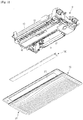
FIG. 1 is an exploded perspective view showing an indoor unit of an air conditioner according to an embodiment of the present invention, and a blade unit applied to the indoor unit. -
FIG. 2 is a cross-sectional view schematically showing an indoor unit of an air conditioner according to an embodiment of the present invention. -
FIG. 3 is an exploded perspective view showing the blade unit according to an embodiment of the present invention. -
FIG. 4 is a cross-sectional view of the blade unit cut along a line A-A ofFIG. 3 . -
FIG. 5 is a side view showing a blade in which a coupling member ofFIG. 3 is formed. -
FIG. 6 shows a buffer member in the blade unit ofFIG. 3 . -
FIG. 7 shows a side of the butter member ofFIG. 6 in which a buffer groove is formed. -
FIG. 8 shows a connection member of the blade unit ofFIG. 3 -
FIG. 9 is a front view showing a side of the connection member ofFIG. 8 in which a connection groove is formed. -
FIG. 10 shows a third coupling member of the blade unit ofFIG. 3 . -
FIG. 11 is an exploded perspective view showing a configuration of the third coupling member ofFIG. 10 . -
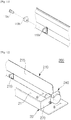
FIG. 12 shows a blade unit according to another embodiment of the present invention. -
FIG. 13 is an exploded perspective view showing a configuration of the blade unit ofFIG. 12 . -
FIG. 14 is a cross-sectional view of the blade unit cut along a line B-B ofFIG. 12 . -
FIG. 15 shows a modified example of the blade unit ofFIG. 12 . -
FIG. 16 is an exploded perspective view showing a blade unit ofFIG. 15 . -
FIG. 17 shows a blade unit according to another embodiment of the present invention. - Hereinafter, preferred embodiments of the present invention will be described in detail.
- Also, hereinafter, for convenience of description, an indoor unit of a ceiling type air conditioner will be described as an example. However, a blade unit according to an embodiment of the present invention can be applied to an indoor unit of another type air conditioner, such as an indoor unit of a stand type air conditioner and an indoor unit of a wall-mounted air conditioner.
-
FIG. 1 is an exploded perspective view showing an indoor unit of an air conditioner according to an embodiment of the present invention, and a blade unit applied to the indoor unit, andFIG. 2 is a cross-sectional view schematically showing an indoor unit of an air conditioner according to an embodiment of the present invention. - Referring to
FIGS. 1 and2 , anindoor unit 1 of an air conditioner according to an embodiment of the present invention may include amain body 10 configured to be hung on or embedded into a ceiling, and abottom panel 20 coupled with the lower part of themain body 10. - The
main body 10 may be in the shape of a box, and may include aheat exchanger 12 configured to heat-exchange inhaled indoor air with refrigerants, ablower fan 11 configured to make air flow forcedly, and acontrol unit 17 configured to control operations of theindoor unit 1 of the air conditioner. - The
main body 10 may include anupper plate 10a andside plates 10b forming the front, back, left, and right appearances of the air conditioner. Themain body 10 may include ascroll part 15 configured to guide air heat-exchanged through theheat exchanger 12 towards anoutlet 13. - In the lower part of the
main body 10, aninlet 14 configured to inhale indoor air to the inside of themain body 10, and theoutlet 13 configured to discharge heat-exchanged air to the indoor space may be provided. In theoutlet 13, a wind-direction control member 19 may be provided to adjust the left-right direction of discharged air. - The
heat exchanger 12 may include atube 12b through which refrigerants flow, and a plurality of heat-exchange pins 12b contacting thetube 12a to widen a heat transfer area. Theheat exchanger 12 may be inclined to be at nearly right angles to the direction of air flow. - Between the heat-
exchanger 12 and theinlet 14, aguide rib 16 may be provided to guide indoor air inhaled into the inside of themain body 10 through theinlet 14 towards theheat exchanger 12. Theguide rib 16 may be inclined to be at nearly right angles to the position of theheat exchanger 12. - Below the
heat exchanger 12, adrain cover 18 may be provided to collect condensation water generated from theheat exchanger 12. Condensation water collected in thedrain cover 18 may be drained to the outside through a drainage hose (not shown). - The
blower fan 11 may be rotated by a driving force of a driving motor (not shown) to make air flow forcedly. A rotatingshaft 11 a of theblower fan 11 may be disposed to be nearly horizontal to the ground. Theblower fan 11 may be a crossflow fan. - The
bottom panel 20 may include agrill 30 disposed to correspond to theinlet 14 in order to prevent foreign materials from entering the inside of themain body 10, and apanel outlet 21 disposed to correspond to theoutlet 13. In thepanel outlet 21, ablade unit 100 may be rotatably disposed to open or close thepanel outlet 21 or to adjust the up-down direction of discharged air. Thepanel outlet 21, which is formed at thebottom panel 20, may be connected to theoutlet 13. Accordingly, in the following description, theoutlet 13 and thepanel outlet 21 will be collectively called anoutlet 21. - The
bottom panel 20 may include afilter member 24 configured to filter out foreign materials from air entered the inside of themain body 10 through theinlet 14. - If the
filter member 24 is used for long periods of time to collect many foreign materials therein, thefilter member 24 may be cleaned or replaced with new one. In this case, in order to easily detach thefilter member 24, thegrill 30 may be configured to be selectively opened with respect to thebottom panel 20. - The
grill 30 may rotate to be opened or closed in the state in which it is fixed and supported on thebottom panel 20 at its rear part. - The
grill 30 may be disposed in front of thefilter member 24 of thebottom panel 20, and at least one part of thegrill 30 may be cut to form agrill inlet 31. - Hereinafter, the
blade unit 100 according to an embodiment of the present invention will be described in detail. -
FIG. 3 is an exploded perspective view showing theblade unit 100 according to an embodiment of the present invention,FIG. 4 is a cross-sectional view of theblade unit 100 cut along a line A-A ofFIG. 3 ,FIG. 5 is a side view showing a blade in which a coupling member ofFIG. 3 is formed,FIG. 6 shows a buffer member in theblade unit 100 ofFIG. 3 ,FIG. 7 shows a side of the butter member ofFIG. 6 in which a buffer groove is formed,FIG. 8 shows a connection member of theblade unit 100 ofFIG. 3 ,FIG. 9 is a front view showing a side of the connection member ofFIG. 8 in which a connection groove is formed,FIG. 10 shows a third coupling member of theblade unit 100 ofFIG. 3 , andFIG. 11 is an exploded perspective view showing a configuration of the third coupling member ofFIG. 10 . - Referring to
FIGS. 3 to 11 , theblade unit 100 may include ablade 110. Theblade unit 100 may be configured such that theblade 110 disposed in theoutlet 21 rotates to adjust the direction of air heat-exchanged in and discharged from the inside of themain body 10. - The
blade 110 may be coupled with one edge of thebottom panel 20 so as to be rotatable in theoutlet 21, as shown inFIG. 1 . More specifically, theblade 110 may be hinge-coupled with one edge of thebottom panel 20 to be rotatable. Theblade 110 may have a shape corresponding to theoutlet 21 in order to open or close theoutlet 21. Theblade 110 may be disposed in the inside of theoutlet 21, and configured to rotate on the axis of its one edge hinge-coupled with thebottom panel 20. - According to an example, the
blade 110 may include abody part 115, andcoupling members - The
body part 115 may have a shape corresponding to theoutlet 21. Thebody part 115 may be in the shape of a rectangular plate. The section of thebody part 115 may be smaller than the section of theoutlet 21 so that thebody part 115 can be positioned in the inside of theoutlet 21. - The
coupling members body part 115. Thecoupling members body part 115 with themain body 10 or thebottom panel 20 such that thebody part 115 is rotatable. - The
coupling members coupling members body part 115. Accordingly, theblade 110 can rotate on the axis of the straight line formed by the plurality ofcoupling members - The plurality of
coupling members body part 115. The plurality ofcoupling members first coupling member 111 and a second coupling member (not shown). Thefirst coupling member 111 may be, as shown inFIG. 3 , connected to amotor 140 which will be described later. The second coupling member may be positioned to face thefirst coupling member 111 on theblade 110. The second coupling member may be connected to themain body 10 or thebottom panel 20 such that theblade 110 is rotatable. - As shown in
FIG. 5 , thefirst coupling member 111 may include acoupling groove 112 and a fixinghole 113. - The
coupling groove 112 may be formed in one side of thefirst coupling member 111. Thecoupling groove 112 may be, as shown inFIG. 3 , formed in the side of thefirst coupling member 111 facing themotor 140 which will be described later. Abuffer member 120 which will be described later may be inserted into thecoupling groove 112. Thecoupling groove 112 may have a shape corresponding to the shape of thebuffer member 120 which will be described. - The fixing
hole 113 may be formed in a surface of thecoupling groove 112 which is face the opening of thecoupling groove 112. Abuffer protrusion 122 of thebuffer member 120 which will be described later may be inserted into the fixinghole 113. If thebuffer protrusion 122 is inserted into the fixinghole 113, the fixinghole 113 may fix thebuffer member 120 at thefirst coupling member 111. However, the fixinghole 113 may be omitted. - The second coupling member may be positioned to face the
first coupling member 111 on theblade 110. The second coupling member may be hinge-coupled with themain body 10 or thebottom panel 20 so that theblade 110 can rotate. - As shown in
FIG. 3 , thecoupling members third coupling member 119. Thethird coupling member 119 may be positioned between thefirst coupling member 111 and the second coupling member. Thethird coupling member 119 may be positioned on the straight line formed by thefirst coupling member 111 and the second coupling member. Thethird coupling member 119 may be hinge-coupled with themain body 10 or thebottom panel 20 so that theblade 110 can rotate. Also, a plurality ofthird coupling members 119 may be arranged at regular intervals between thefirst coupling member 111 and the second coupling member. - As shown in
FIGS. 10 and11 , thethird coupling member 119 may include anexternal frame 119a, abuffer part 119b, and aprotrusion 119c. - The
external frame 119a may form the outer side portion of thethird coupling member 119. Thebuffer part 119b may be inserted into the inside of theexternal frame 119a. Thebuffer part 119b may be made of a material having a restoring force. Also, thebutter part 119b may be made of a material having elasticity. One end of theprotrusion 119c may be inserted into thebuffer part 119b, and the other end of theprotrusion 119c may extend from thebuffer part 119b. Theprotrusion 119c may be coupled with themain body 10 or thebottom panel 20. According to the above-described configuration, thethird coupling member 119 may enable theblade 110 to rotate in theoutlet 21 by changing the shape of thebuffer part 119b. - The
blade unit 100 may further include themotor 140. - The
motor 140 may be installed in the inside of themain body 10 to generate a rotatory force that is transferred to theblade 110. Themotor 140 may include arotation transfer member 150. Therotation transfer member 150 may transfer a rotatory force generated by themotor 140 to theblade 110. The configuration of therotation transfer member 150 will be described later. - The
blade unit 100 may further include thebuffer member 120. - The
buffer member 120 may be connected to theblade 110 and therotation transfer member 150 of themotor 140. Thebuffer member 120 may be coupled with theblade 110 at one end, while surrounding a part of therotation transfer member 150. Thebuffer member 120 may be inserted into one end of theblade 110, while surrounding a part of therotation transfer member 150. Thebuffer member 120 may transfer a rotatory force to theblade 110, while rotating together with therotation transfer member 150. - The
buffer member 120 may be inserted into thecoupling groove 112 of thefirst coupling part 111. Thebuffer member 120 may have a shape corresponding to thecoupling groove 112. Thebuffer member 120 may be in the shape of a faceted pillar having at least one edge in the longitudinal direction. Accordingly, thebuffer member 120 may rotate together with thefirst coupling member 111 in the state in which it is inserted into thecoupling groove 112. - According to an example, the
buffer member 120 may include abuffer body part 121, abuffer protrusion 122, and abuffer groove 123. - The
buffer body part 121 may have a shape corresponding to thecoupling groove 112. As shown inFIG. 4 , thebuffer body part 121 may be inserted into and rested in the inside of thecoupling groove 112 of thefirst coupling member 111. Thebuffer body part 121 may include a stoppingpart 121 a at one end. The stoppingpart 121 a may extend from one end of thebuffer body part 121, and be caught by thefirst coupling member 111 when thebuffer body part 121 is completely inserted into thecoupling groove 112. However, the stoppingpart 121 a may be omitted. - The
buffer protrusion 122 may be formed at one end of thebuffer body part 121. Thebuffer protrusion 122 may be positioned to correspond to the fixinghole 113 when thebuffer body part 121 is inserted into thecoupling groove 112. Thebuffer protrusion 122 may extend from thebuffer body part 121. Thebuffer protrusion 122 may be inserted into the fixinghole 113 of thefirst coupling member 111. - The
buffer protrusion 122 may include afirst protrusion 122b and asecond protrusion 122a. Thefirst protrusion 122b may extend from thebuffer body part 121. Thefirst protrusion 122b may connect thebuffer body part 121 to thesecond protrusion 122a. Thefirst protrusion 122b may be inserted into the fixinghole 113. The section of thefirst protrusion 122b may correspond to the inside section of the fixinghole 113. - The
second protrusion 122a may be positioned at one end of thefirst protrusion 122b. Thesecond protrusion 122a may have a shape tapering from its part connected to thefirst protrusion 122b. Thesecond protrusion 122a may be in the shape of a cone. The section of one end of thesecond protrusion 122a may be larger than that of the fixinggroove 113. One end of thesecond protrusion 122a may be caught by the outer edge of the fixinghole 113 when thebuffer member 120 is completely inserted into thecoupling groove 112. - The
buffer groove 123 may be formed in a portion of thebuffer body part 121. Thebuffer groove 123 may be formed in a portion of thebuffer body part 121 that is opposite to thebuffer protrusion 122. Therotation transfer member 150 which will be described later may be inserted into thebuffer groove 123. Thebuffer groove 123 may have a shape corresponding to therotation transfer member 150. - The
buffer groove 123 may be in the shape of a pillar having at least one edge in the longitudinal direction. Thebuffer groove 123 may be in the shape of a pillar whose section is in the shape of "+". Thebuffer groove 123 may be in the shape of a faceted pillar having at least one edge at the side. Thebuffer groove 123 may rotate together with therotation transfer member 150 inserted thereinto to receive a rotatory force. - The
buffer member 120 may be made of a material having a restoring force. Also, thebuffer member 120 may be made of a material having elasticity. Accordingly, even when therotation transfer member 150 and theblade 110 are not aligned on a straight line, the shape of thebuffer member 120 may change so as to locate theblade 110 at a predetermined position. Also, thebuffer member 120 may prevent vibrations and noise from being generated by vibrations of themotor 140 and rotation of theblade 110. According to an example, thebuffer member 120 may include rubber. - The
rotation transfer member 150 may be connected to themotor 140 to transfer a rotatory force generated by themotor 140 to theblade 110. Therotation transfer member 150 may include arotation shaft 151 and aconnection member 152. - The
rotation shaft 151 may extend from one part of themotor 140. Therotation shaft 151 may receive a rotatory force directly from themotor 140 and rotate. - The
connection member 152 may be coupled with therotation shaft 151 at one end, and coupled with thebuffer member 120 at the other end. Theconnection member 152 may rotate together with therotation shaft 151 to transfer a rotatory force to thebuffer member 120 connected thereto. - As shown in
FIG. 8 , theconnection member 152 may include aconnection body part 152a, aconnection protrusion 152b, and aconnection groove 152c. - The
connection body part 152a may be coupled with therotation shaft 151 at one end. In the one end of theconnection body part 152a, aconnection groove 152c may be formed. Therotation shaft 151 may be inserted into theconnection groove 152c. Theconnection groove 152c may be configured such that theconnection member 152 can rotate together with therotation shaft 151 in the state in which therotation shaft 151 is inserted into theconnection groove 152c. Theconnection groove 152c may have a shape corresponding to therotation shaft 151. - The
connection protrusion 152b may extend from the other end of theconnection body part 152a. Theconnection protrusion 152b may be formed in a portion of theconnection body part 152a that is opposite to theconnection groove 152. - The
connection protrusion 152b may be coupled with thebuffer member 120. Theconnection protrusion 152b may be inserted into thebuffer groove 123. Theconnection protrusion 152b may have a shape corresponding to thebuffer groove 123. Theconnection protrusion 152b and thebuffer groove 123 may be in the shape of a pillar whose section is in the shape of "+". Theconnection protrusion 152b and thebuffer groove 123 may be in the shape of a faceted pillar having at least one edge at the side. Theconnection protrusion 152b may rotate together with thebuffer member 120 in the state in which it is inserted into thebuffer groove 123. - The
connection member 152 may be made of a material having stiffness that is lower than that of therotation shaft 151 of themotor 140. For example, therotation shaft 151 of themotor 140 may be made of a metal material, and theconnection member 152 may be made of a plastic material. Accordingly, theconnection member 152 may prevent thebuffer member 120 from being damaged upon rotation, compared to when therotation shaft 151 made of a metal material is directly connected to thebuffer member 120. - In general, if the
main body 10 is installed non-horizontally, therotation transfer member 150 and theblade 110 may be not aligned on a straight line. In this case, the rotation axis of theblade 110 may change to disable theblade 110 to rotate, or theblade 110 may make vibrations and noise upon rotation. - However, in the
blade unit 100 according to the above-described embodiment of the present invention, thebuffer member 120 may be provided between themotor 140 and theblade 110. Thebuffer member 120 may be made of a material having a restoring force to change its shape according to an external force. Accordingly, when therotation transfer member 150 and theblade 110 are not aligned on a straight line, the shape of thebuffer member 120 may change partially so as to locate theblade 110 at an appropriate position where it can rotate. Therefore, theblade 110 can be easily rotated, and also, vibrations and noise that can be generated due to rotation of theblade 110 can be prevented. - Hereinafter, a blade unit according to another embodiment of the present invention will be described.
-
FIG. 12 shows a blade unit according to another embodiment of the present invention,FIG. 13 is an exploded perspective view showing a configuration of the blade unit ofFIG. 12 , andFIG. 14 is a cross-sectional view of the blade unit cut along a line B-B ofFIG. 12 . - Referring to
FIGS. 12 ,13, and 14 , ablade unit 200 may include ablade 210, abuffer member 220, amotor 240, arotation transfer member 250, and aguide hole 271 to guide therotation transfer member 250. Comparing to theblade unit 100 ofFIG. 3 , theblade unit 200 may further include theguide hole 271 to guide therotation transfer member 250, and the remaining components of theblade unit 200 may be the same as those of theblade unit 100 ofFIG. 3 . Hereinafter, descriptions about the same components of theblade unit 200 as those of theblade unit 100 ofFIG. 3 will be omitted, and theblade unit 200 will be described based on differences from theblade unit 100 ofFIG. 3 . - The
guide hole 271 may be disposed in apartition wall 270 forming theoutlet 21 in the inside of thebottom panel 20. Theguide hole 271 may be formed on a straight line on which afirst coupling member 211 of theblade 210 and therotation transfer member 250 are aligned. Theguide hole 271 may function as a passage through which themotor 240 is connected to theblade 210. - The
guide hole 271 may guide the position of therotation transfer member 250 connected to themotor 240 when themain body 10 or thebottom panel 20 is installed non-horizontally. Therotation transfer member 250 may be supported by theguide hole 271 when themain body 10 or thebottom panel 20 is maintained non-horizontally. Accordingly, therotation transfer member 250 may be maintained at a predetermined position even when themain body 10 or thebottom panel 20 is installed non-horizontally. Also, since therotation transfer member 250 is supported by theguide hole 271 when themain body 10 or thebottom panel 20 is installed non-horizontally, theguide hole 271 can reduce load transferred to therotation transfer member 250. Accordingly, it is possible to prevent theblade unit 200 from being damaged, while improving the reliability of theblade unit 200. - Hereinafter, a modified example of the
blade unit 200 will be described. -
FIG. 15 shows a modified example of theblade unit 200 ofFIG. 12 , andFIG. 16 is an exploded perspective view showing a blade unit ofFIG. 15 . - Referring to
FIGS. 15 and 16 , ablade unit 201 may include theblade 210, thebuffer member 220, themotor 240, therotation transfer member 250, theguide hole 271, and agear unit 280. Comparing to theblade unit 200 ofFIG. 14 , theblade unit 201 may further include thegear unit 280, and the remaining components of theblade unit 201 may be the same as those of theblade unit 200 ofFIG. 14 . Hereinafter, theblade unit 201 will be described based on differences from theblade unit 200 ofFIG. 14 . - The
gear unit 280 may be configured to transfer greater torque to theblade 210 although thesame motor 240 is used. According to an example, thegear unit 280 may include afirst gear 281 and asecond gear 282. Thefirst gear 281 may connect arotation shaft 281 a to themotor 240. Thesecond gear 282 may couple arotation shaft 282a with theblade 210. Thesecond gear 282 may have a greater diameter than thefirst gear 281. - The
first gear 281 may be interlocked with thesecond gear 282. According to the above-described configuration, thesecond gear 282 can transfer greater torque to theblade 210 than thefirst gear 281. Thegear unit 280 may generate great torque although the same motor is used, so as to reduce vibrations and noise that are generated upon use of thehigh capacity motor 240. - Hereinafter, a blade unit according to another embodiment of the present invention will be described.
-
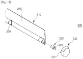
FIG. 17 shows a blade unit according to another embodiment of the present invention. - Referring to
FIG. 17 , ablade unit 300 may include ablade 310, abuffer member 320, amotor 340, and arotation transfer member 341. Comparing to theblade unit 100 ofFIG. 3 , therotation transfer member 341 of theblade unit 300 is different from the corresponding one of theblade unit 100 ofFIG. 3 , and the remaining components of theblade unit 300 are the same as those of theblade unit 100 ofFIG. 3 . Hereinafter, theblade unit 300 will be described based on differences from theblade unit 100 ofFIG. 3 . - The
rotation transfer member 341 may be provided as a rotation shaft extending from one end of themotor 340. Unlike theblade unit 100 ofFIG. 3 , in theblade unit 300, therotation shaft 341 may be directly coupled with thebuffer member 320. Therotation shaft 341 may be inserted into abuffer groove 323 formed in thebuffer member 320. Accordingly, therotation shaft 341 may rotate due to a rotatory force transferred from themotor 340 in the state in which it is inserted into the buffer groove 232, and transfer the rotatory force to theblade 310. - It will be apparent to those skilled in the art that various modifications and variations can be made in the present invention without departing from the spirit or scope of the inventions. Thus, it is intended that the present invention covers the modifications and variations of this invention provided they come within the scope of the appended claims and their equivalents.
Claims (21)
- An indoor unit of an air conditioner, comprising:a main body including an outlet; anda blade unit configured to adjust a direction in which air discharged from the outlet is discharged,wherein the blade unit comprises:a blade coupled with the main body to be rotatable in the outlet;a motor including a rotation transfer member, and configured to generate a rotatory force that is transferred to the blade; anda buffer member made of a material having a restoring force, coupled with the blade at one end, and surrounding a part of the rotation transfer member.
- The indoor unit according to claim 1, wherein the buffer member is inserted into one end of the blade while surrounding the part of the rotation transfer member.
- The indoor unit according to claim 2, wherein the blade comprises a coupling member in which a coupling groove is formed, at one edge, and the buffer member has a shape corresponding to the coupling groove to be inserted into the coupling groove.
- The indoor unit according to claim 1, wherein the buffer member includes a buffer groove into which the rotation transfer member is inserted.
- The indoor unit according to claim 3, wherein the coupling member comprises:a first coupling member connected to the rotation transfer member; anda second coupling member disposed at the blade to face the first coupling member, and connected to the main body such that the blade is rotatable.
- The indoor unit according to claim 5, wherein the coupling member further comprises a third coupling member positioned between the first coupling member and the second coupling member, and
wherein the third coupling member couples the blade with the main body such that the blade is rotatable. - The indoor unit according to claim 6, wherein the third coupling member comprises:a protrusion coupled with a part of the main body; anda buffer part made of a material having a restoring force, and surrounding the protrusion.
- The indoor unit according to claim 1, wherein the rotation transfer member comprises:a rotation shaft extending from the motor, and configured to transfer a rotatory force generated by the motor; anda connection member coupled with the rotation shaft at one end, and coupled with the buffer member at the other end.
- The indoor unit according to claim 8, wherein the connection member comprises:a connection body part coupled with the rotation shaft; anda connection protrusion extending from the connection body part, and coupled with the buffer member.
- The indoor unit according to claim 8, wherein the connection member is made of a material having stiffness that is lower than stiffness of the rotation shaft.
- A blade unit configured to adjust a direction of air heat-exchanged and then discharged from an outlet provided in an indoor unit of an air conditioner, the blade unit comprising:a blade coupled with a main body to be rotatable in the outlet;a motor including a rotation transfer member, and configured to generate a rotatory force that is transferred to the blade; anda buffer member made of a material having a restoring force, and coupled with the blade at one end, wherein a part of the rotation transfer member is inserted into and coupled with the buffer member.
- The blade unit according to claim 11, wherein the blade comprises a coupling member in which a coupling groove is formed, at one edge, and the buffer member is inserted into the coupling groove.
- The blade unit according to claim 11, wherein the buffer member includes a buffer groove into which the rotation transfer member is inserted.
- The blade unit according to claim 11, wherein the rotation transfer member comprises:a rotation shaft extending from the motor, and configured to transfer a rotatory force generated by the motor; anda connection member coupled with the rotation shaft at one end, and coupled with the buffer member at the other end.
- The blade unit according to claim 14, wherein the connection member comprises:a connection body part coupled with the rotation shaft; anda connection protrusion extending from the connection body part, and coupled with the buffer member.
- The blade unit according to claim 14, wherein the connection member is made of a material having stiffness that is lower than stiffness of the rotation shaft.
- An indoor unit of an air conditioner, comprising:a main body mounted on a ceiling;a bottom panel having an outlet at one part, and coupled with a lower part of the main body; anda blade unit configured to adjust a direction in which air discharged from the outlet is discharged,wherein the blade unit comprises:a blade coupled with the bottom panel to be rotatable in the outlet;a motor including a rotation transfer member, and configured to generate a rotatory force that is transferred to the blade; anda buffer member made of a material having a restoring force, and connected to the rotation transfer member and the blade such that the blade is maintained horizontally in the outlet even when the main body is installed non-horizontally.
- The indoor unit according to claim 17, wherein the buffer member includes a buffer groove into which a part of the rotation transfer member is inserted.
- The indoor unit according to claim 17, wherein the blade comprises a coupling member in which a coupling groove is formed, at one edge, and the buffer member is inserted into the coupling groove.
- The indoor unit according to claim 17, wherein the rotation transfer member comprises:a rotation shaft extending from the motor, and configured to transfer a rotatory force generated by the motor; anda connection member coupled with the rotation shaft at one end, and coupled with the buffer member at the other end.
- The indoor unit according to claim 20, wherein the connection member is made of a material having stiffness that is lower than stiffness of the rotation shaft.
Priority Applications (2)
| Application Number | Priority Date | Filing Date | Title |
|---|---|---|---|
| EP20201610.1A EP3783273B1 (en) | 2014-02-28 | 2015-02-25 | Indoor unit of air conditioner and blade unit applied to same |
| EP22150375.8A EP3998430A1 (en) | 2014-02-28 | 2015-02-25 | Indoor unit of air conditioner and blade unit applied to same |
Applications Claiming Priority (3)
| Application Number | Priority Date | Filing Date | Title |
|---|---|---|---|
| KR20140024564 | 2014-02-28 | ||
| KR1020140155572A KR102335152B1 (en) | 2014-02-28 | 2014-11-10 | Indoor unit of air-conditioner and blade unit applying the same |
| PCT/KR2015/001808 WO2015130073A2 (en) | 2014-02-28 | 2015-02-25 | Indoor unit of air conditioner and blade unit applied to same |
Related Child Applications (2)
| Application Number | Title | Priority Date | Filing Date |
|---|---|---|---|
| EP20201610.1A Division EP3783273B1 (en) | 2014-02-28 | 2015-02-25 | Indoor unit of air conditioner and blade unit applied to same |
| EP22150375.8A Division EP3998430A1 (en) | 2014-02-28 | 2015-02-25 | Indoor unit of air conditioner and blade unit applied to same |
Publications (2)
| Publication Number | Publication Date |
|---|---|
| EP3115709A2 true EP3115709A2 (en) | 2017-01-11 |
| EP3115709A4 EP3115709A4 (en) | 2018-01-24 |
Family
ID=54243407
Family Applications (3)
| Application Number | Title | Priority Date | Filing Date |
|---|---|---|---|
| EP22150375.8A Pending EP3998430A1 (en) | 2014-02-28 | 2015-02-25 | Indoor unit of air conditioner and blade unit applied to same |
| EP15754617.7A Withdrawn EP3115709A4 (en) | 2014-02-28 | 2015-02-25 | Indoor unit of air conditioner and blade unit applied to same |
| EP20201610.1A Active EP3783273B1 (en) | 2014-02-28 | 2015-02-25 | Indoor unit of air conditioner and blade unit applied to same |
Family Applications Before (1)
| Application Number | Title | Priority Date | Filing Date |
|---|---|---|---|
| EP22150375.8A Pending EP3998430A1 (en) | 2014-02-28 | 2015-02-25 | Indoor unit of air conditioner and blade unit applied to same |
Family Applications After (1)
| Application Number | Title | Priority Date | Filing Date |
|---|---|---|---|
| EP20201610.1A Active EP3783273B1 (en) | 2014-02-28 | 2015-02-25 | Indoor unit of air conditioner and blade unit applied to same |
Country Status (6)
| Country | Link |
|---|---|
| US (1) | US10746456B2 (en) |
| EP (3) | EP3998430A1 (en) |
| KR (3) | KR102335152B1 (en) |
| CN (2) | CN110986158B (en) |
| DE (1) | DE202015009877U1 (en) |
| ES (1) | ES2909737T3 (en) |
Cited By (1)
| Publication number | Priority date | Publication date | Assignee | Title |
|---|---|---|---|---|
| EP3779316A4 (en) * | 2018-03-30 | 2022-01-05 | Fujitsu General Limited | Ceiling-embedded air conditioner |
Families Citing this family (12)
| Publication number | Priority date | Publication date | Assignee | Title |
|---|---|---|---|---|
| EP4160097A3 (en) * | 2016-12-21 | 2023-07-05 | Samsung Electronics Co., Ltd. | Air conditioner |
| KR102401787B1 (en) * | 2017-04-28 | 2022-05-26 | 삼성전자주식회사 | Air conditioner |
| KR102466274B1 (en) | 2017-04-28 | 2022-11-11 | 삼성전자주식회사 | Air conditioner |
| CN111295553B (en) * | 2017-09-06 | 2021-08-20 | Lg电子株式会社 | Ceiling type indoor unit of air conditioner |
| JP7106284B2 (en) * | 2018-02-05 | 2022-07-26 | 三菱重工サーマルシステムズ株式会社 | Louver, air conditioner, and method for assembling air conditioner |
| KR102562554B1 (en) | 2018-02-13 | 2023-08-03 | 삼성전자주식회사 | Air cleaner and home appliance |
| JP7319767B2 (en) * | 2018-09-14 | 2023-08-02 | シャープ株式会社 | Wind direction change member |
| KR102600958B1 (en) * | 2018-09-21 | 2023-11-14 | 삼성전자주식회사 | Air Conditioner |
| CN112797597B (en) * | 2021-01-07 | 2022-05-27 | 珠海格力电器股份有限公司 | Air conditioning equipment control method and device, electronic equipment and storage medium |
| CN113503584B (en) * | 2021-07-30 | 2022-11-18 | 青岛海尔空调器有限总公司 | Air conditioner indoor unit and air conditioner |
| CN114087686B (en) * | 2021-11-24 | 2022-12-02 | 华祥(中国)高纤有限公司 | Energy-saving type temperature and humidity automatic adjusting air conditioning unit |
| CN117847762A (en) * | 2022-10-07 | 2024-04-09 | Lg电子株式会社 | Air conditioner |
Family Cites Families (37)
| Publication number | Priority date | Publication date | Assignee | Title |
|---|---|---|---|---|
| US2117529A (en) * | 1936-08-22 | 1938-05-17 | Detroit Lubricator Co | Temperature control apparatus |
| US2698570A (en) * | 1951-11-07 | 1955-01-04 | Archie S Feinberg | Temperature control air deflecting louver |
| US3063357A (en) * | 1960-11-25 | 1962-11-13 | Westinghouse Electric Corp | Air distributing device |
| GB2143028B (en) | 1983-07-01 | 1986-11-19 | Matsushita Electric Ind Co Ltd | Discharge direction control device for air conditioner |
| US4782999A (en) * | 1987-08-21 | 1988-11-08 | Kabushiki Kaisha Toshiba | Air conditioning apparatus and grille control method thereof |
| US5022583A (en) * | 1990-07-16 | 1991-06-11 | Bruens Jean Marie | Register blade mover |
| GB2270154B (en) * | 1992-08-26 | 1996-08-28 | Toshiba Kk | Air conditioner |
| JP3320550B2 (en) * | 1994-04-28 | 2002-09-03 | 豊田合成株式会社 | Oscillating blade mounting device for air conditioner |
| JP3356257B2 (en) * | 1996-06-06 | 2002-12-16 | 株式会社富士通ゼネラル | Air conditioner |
| JPH10148349A (en) * | 1996-11-19 | 1998-06-02 | Matsushita Electric Ind Co Ltd | Air flow direction changing device for air conditioner |
| JPH1114134A (en) * | 1997-06-20 | 1999-01-22 | Fujitsu General Ltd | Indoor machine of air conditioner |
| JP3765357B2 (en) * | 1997-06-20 | 2006-04-12 | 株式会社富士通ゼネラル | Air conditioner |
| JP3885845B2 (en) * | 1998-03-16 | 2007-02-28 | 株式会社富士通ゼネラル | Air conditioner |
| JP2002310448A (en) * | 2001-04-05 | 2002-10-23 | Fujitsu General Ltd | Air conditioner |
| US6890159B2 (en) * | 2002-03-19 | 2005-05-10 | Denso Corporation | Air blower with fan unable to contact motor housing |
| CN2567496Y (en) * | 2002-07-04 | 2003-08-20 | 珠海格力电器股份有限公司 | Indoor unit of cabinet air conditioner |
| JP4110863B2 (en) * | 2002-07-12 | 2008-07-02 | 株式会社富士通ゼネラル | Air conditioner |
| KR100530893B1 (en) * | 2002-10-21 | 2005-11-24 | 위니아만도 주식회사 | An installing structure of horizontal blade for a room air-conditioner |
| KR100596254B1 (en) * | 2004-06-17 | 2006-07-03 | 엘지전자 주식회사 | Indoor unit for air conditioner |
| EP1783437A4 (en) * | 2004-07-14 | 2009-04-01 | Daikin Ind Ltd | Indoor unit for air conditioner |
| AU2005265485B2 (en) * | 2004-07-27 | 2009-02-05 | Lg Electronics Inc. | Air conditioner |
| KR101271060B1 (en) * | 2005-12-21 | 2013-06-04 | 삼성전자주식회사 | Ceiling Type Air Conditioner |
| ES2442690T3 (en) | 2005-12-26 | 2014-02-12 | Lg Electronics Inc. | Indoor unit of air conditioner |
| WO2007081083A1 (en) * | 2006-01-16 | 2007-07-19 | Lg Electronics, Inc. | Indoor unit for air conditioner |
| CN101114185B (en) * | 2006-07-26 | 2010-12-29 | 鸿富锦精密工业(深圳)有限公司 | Air flow automatically guiding device |
| KR20080078188A (en) | 2007-02-22 | 2008-08-27 | 삼성전자주식회사 | Air-conditioner |
| KR101340528B1 (en) * | 2008-02-04 | 2013-12-11 | 엘지전자 주식회사 | Ceiling type air conditioner |
| CN201246854Y (en) * | 2008-07-03 | 2009-05-27 | Tcl集团股份有限公司 | Wind guide apparatus of split wall hanging type air conditioner indoor machine |
| CN101762005B (en) * | 2008-12-24 | 2012-10-10 | 珠海格力电器股份有限公司 | Air-out panel of air-conditioner |
| US20130167579A1 (en) * | 2010-10-28 | 2013-07-04 | Roberta Jean Delgadillo | Salad Bar Cooler |
| KR20120075996A (en) | 2010-12-29 | 2012-07-09 | 위니아만도 주식회사 | Moving freely prevention device of blade for air-conditioner |
| CN102620399B (en) * | 2011-01-30 | 2013-12-11 | 昌硕科技(上海)有限公司 | Air conditioner |
| CN103765119B (en) * | 2011-10-14 | 2016-08-17 | 松下电器产业株式会社 | Air conditioner and the indoor set of air conditioner |
| CN103375841B (en) | 2012-04-13 | 2015-07-08 | 珠海格力电器股份有限公司 | Wall-mounted air conditioner indoor unit |
| CN103486715B (en) * | 2012-06-12 | 2016-03-16 | 珠海格力电器股份有限公司 | Air deflector drive structure and comprise the air-conditioner of this transmission mechanism |
| JP5590081B2 (en) * | 2012-09-04 | 2014-09-17 | ダイキン工業株式会社 | Cross flow fan |
| KR102626405B1 (en) * | 2016-05-09 | 2024-01-18 | 엘지전자 주식회사 | Charging device for cleaner |
-
2014
- 2014-11-10 KR KR1020140155572A patent/KR102335152B1/en active IP Right Grant
-
2015
- 2015-02-25 DE DE202015009877.0U patent/DE202015009877U1/en active Active
- 2015-02-25 US US15/122,407 patent/US10746456B2/en active Active
- 2015-02-25 EP EP22150375.8A patent/EP3998430A1/en active Pending
- 2015-02-25 CN CN201911353219.9A patent/CN110986158B/en active Active
- 2015-02-25 ES ES20201610T patent/ES2909737T3/en active Active
- 2015-02-25 CN CN201580011189.7A patent/CN106662358B/en active Active
- 2015-02-25 EP EP15754617.7A patent/EP3115709A4/en not_active Withdrawn
- 2015-02-25 EP EP20201610.1A patent/EP3783273B1/en active Active
-
2021
- 2021-11-30 KR KR1020210168726A patent/KR102458329B1/en active IP Right Grant
-
2022
- 2022-10-19 KR KR1020220135171A patent/KR102646110B1/en active IP Right Grant
Cited By (2)
| Publication number | Priority date | Publication date | Assignee | Title |
|---|---|---|---|---|
| EP3779316A4 (en) * | 2018-03-30 | 2022-01-05 | Fujitsu General Limited | Ceiling-embedded air conditioner |
| US11898762B2 (en) | 2018-03-30 | 2024-02-13 | Fujitsu General Limited | Ceiling-embedded air conditioner |
Also Published As
| Publication number | Publication date |
|---|---|
| KR102458329B1 (en) | 2022-10-25 |
| EP3115709A4 (en) | 2018-01-24 |
| EP3783273A1 (en) | 2021-02-24 |
| US10746456B2 (en) | 2020-08-18 |
| DE202015009877U1 (en) | 2020-12-21 |
| KR20220147057A (en) | 2022-11-02 |
| CN110986158A (en) | 2020-04-10 |
| ES2909737T3 (en) | 2022-05-10 |
| KR20210151736A (en) | 2021-12-14 |
| CN106662358B (en) | 2020-01-21 |
| CN106662358A (en) | 2017-05-10 |
| CN110986158B (en) | 2021-07-13 |
| KR20150102674A (en) | 2015-09-07 |
| EP3998430A1 (en) | 2022-05-18 |
| KR102335152B1 (en) | 2021-12-06 |
| KR102646110B1 (en) | 2024-03-12 |
| US20170067681A1 (en) | 2017-03-09 |
| EP3783273B1 (en) | 2022-02-16 |
Similar Documents
| Publication | Publication Date | Title |
|---|---|---|
| EP3783273B1 (en) | Indoor unit of air conditioner and blade unit applied to same | |
| EP2821716B1 (en) | air conditioner indoor unit comprising a wind-visor for air discharge opening | |
| EP3060855B1 (en) | Indoor unit of ceiling type air-conditioner | |
| EP2997312B1 (en) | Indoor unit of air conditioner | |
| KR102401787B1 (en) | Air conditioner | |
| EP3593061B1 (en) | Air conditioner | |
| KR102425866B1 (en) | Method for controlling air conditioner | |
| KR102217013B1 (en) | Indoor unit of ceiling type air-conditioner | |
| KR20090078477A (en) | A drainage structure of condensate for indoor unit of air conditioner | |
| KR100714591B1 (en) | Inner-door unit of air-conditioner | |
| KR102343464B1 (en) | Indoor unit of ceiling type air-conditioner | |
| KR20080060845A (en) | Indoor unit for air conditioner | |
| KR102425867B1 (en) | Method for controlling air conditioner | |
| KR102451312B1 (en) | Indoor unit of air conditioner | |
| KR100584303B1 (en) | Air conditioner |
Legal Events
| Date | Code | Title | Description |
|---|---|---|---|
| STAA | Information on the status of an ep patent application or granted ep patent |
Free format text: STATUS: THE INTERNATIONAL PUBLICATION HAS BEEN MADE |
|
| PUAI | Public reference made under article 153(3) epc to a published international application that has entered the european phase |
Free format text: ORIGINAL CODE: 0009012 |
|
| STAA | Information on the status of an ep patent application or granted ep patent |
Free format text: STATUS: REQUEST FOR EXAMINATION WAS MADE |
|
| 17P | Request for examination filed |
Effective date: 20160822 |
|
| AK | Designated contracting states |
Kind code of ref document: A2 Designated state(s): AL AT BE BG CH CY CZ DE DK EE ES FI FR GB GR HR HU IE IS IT LI LT LU LV MC MK MT NL NO PL PT RO RS SE SI SK SM TR |
|
| AX | Request for extension of the european patent |
Extension state: BA ME |
|
| R17D | Deferred search report published (corrected) |
Effective date: 20170112 |
|
| DAX | Request for extension of the european patent (deleted) | ||
| A4 | Supplementary search report drawn up and despatched |
Effective date: 20180103 |
|
| RIC1 | Information provided on ipc code assigned before grant |
Ipc: F24F 13/14 20060101ALI20171220BHEP Ipc: F24F 1/00 20110101ALI20171220BHEP Ipc: F24F 13/24 20060101ALI20171220BHEP Ipc: F24F 13/08 20060101AFI20171220BHEP |
|
| STAA | Information on the status of an ep patent application or granted ep patent |
Free format text: STATUS: EXAMINATION IS IN PROGRESS |
|
| 17Q | First examination report despatched |
Effective date: 20200526 |
|
| STAA | Information on the status of an ep patent application or granted ep patent |
Free format text: STATUS: THE APPLICATION HAS BEEN WITHDRAWN |
|
| 18W | Application withdrawn |
Effective date: 20201020 |