EP3115598A1 - Wind power generation device - Google Patents
Wind power generation device Download PDFInfo
- Publication number
- EP3115598A1 EP3115598A1 EP14884755.1A EP14884755A EP3115598A1 EP 3115598 A1 EP3115598 A1 EP 3115598A1 EP 14884755 A EP14884755 A EP 14884755A EP 3115598 A1 EP3115598 A1 EP 3115598A1
- Authority
- EP
- European Patent Office
- Prior art keywords
- blade
- suction surface
- windmill
- aperture
- space
- Prior art date
- Legal status (The legal status is an assumption and is not a legal conclusion. Google has not performed a legal analysis and makes no representation as to the accuracy of the status listed.)
- Withdrawn
Links
- 238000010248 power generation Methods 0.000 title 1
- 238000000926 separation method Methods 0.000 claims abstract description 80
- 238000005192 partition Methods 0.000 claims description 25
- 230000002787 reinforcement Effects 0.000 claims description 21
- 230000007423 decrease Effects 0.000 description 14
- 230000003247 decreasing effect Effects 0.000 description 12
- 238000010586 diagram Methods 0.000 description 11
- 238000005259 measurement Methods 0.000 description 3
- 238000007664 blowing Methods 0.000 description 1
- 238000001514 detection method Methods 0.000 description 1
- 230000000694 effects Effects 0.000 description 1
- 238000004519 manufacturing process Methods 0.000 description 1
- 230000002093 peripheral effect Effects 0.000 description 1
- 238000003466 welding Methods 0.000 description 1
Images


Classifications
-
- F—MECHANICAL ENGINEERING; LIGHTING; HEATING; WEAPONS; BLASTING
- F03—MACHINES OR ENGINES FOR LIQUIDS; WIND, SPRING, OR WEIGHT MOTORS; PRODUCING MECHANICAL POWER OR A REACTIVE PROPULSIVE THRUST, NOT OTHERWISE PROVIDED FOR
- F03D—WIND MOTORS
- F03D7/00—Controlling wind motors
- F03D7/02—Controlling wind motors the wind motors having rotation axis substantially parallel to the air flow entering the rotor
- F03D7/022—Adjusting aerodynamic properties of the blades
-
- F—MECHANICAL ENGINEERING; LIGHTING; HEATING; WEAPONS; BLASTING
- F03—MACHINES OR ENGINES FOR LIQUIDS; WIND, SPRING, OR WEIGHT MOTORS; PRODUCING MECHANICAL POWER OR A REACTIVE PROPULSIVE THRUST, NOT OTHERWISE PROVIDED FOR
- F03D—WIND MOTORS
- F03D1/00—Wind motors with rotation axis substantially parallel to the air flow entering the rotor
- F03D1/06—Rotors
- F03D1/065—Rotors characterised by their construction elements
- F03D1/0675—Rotors characterised by their construction elements of the blades
-
- F—MECHANICAL ENGINEERING; LIGHTING; HEATING; WEAPONS; BLASTING
- F05—INDEXING SCHEMES RELATING TO ENGINES OR PUMPS IN VARIOUS SUBCLASSES OF CLASSES F01-F04
- F05B—INDEXING SCHEME RELATING TO WIND, SPRING, WEIGHT, INERTIA OR LIKE MOTORS, TO MACHINES OR ENGINES FOR LIQUIDS COVERED BY SUBCLASSES F03B, F03D AND F03G
- F05B2240/00—Components
- F05B2240/20—Rotors
- F05B2240/30—Characteristics of rotor blades, i.e. of any element transforming dynamic fluid energy to or from rotational energy and being attached to a rotor
-
- F—MECHANICAL ENGINEERING; LIGHTING; HEATING; WEAPONS; BLASTING
- F05—INDEXING SCHEMES RELATING TO ENGINES OR PUMPS IN VARIOUS SUBCLASSES OF CLASSES F01-F04
- F05B—INDEXING SCHEME RELATING TO WIND, SPRING, WEIGHT, INERTIA OR LIKE MOTORS, TO MACHINES OR ENGINES FOR LIQUIDS COVERED BY SUBCLASSES F03B, F03D AND F03G
- F05B2240/00—Components
- F05B2240/20—Rotors
- F05B2240/30—Characteristics of rotor blades, i.e. of any element transforming dynamic fluid energy to or from rotational energy and being attached to a rotor
- F05B2240/306—Surface measures
- F05B2240/3062—Vortex generators
-
- F—MECHANICAL ENGINEERING; LIGHTING; HEATING; WEAPONS; BLASTING
- F05—INDEXING SCHEMES RELATING TO ENGINES OR PUMPS IN VARIOUS SUBCLASSES OF CLASSES F01-F04
- F05B—INDEXING SCHEME RELATING TO WIND, SPRING, WEIGHT, INERTIA OR LIKE MOTORS, TO MACHINES OR ENGINES FOR LIQUIDS COVERED BY SUBCLASSES F03B, F03D AND F03G
- F05B2260/00—Function
- F05B2260/60—Fluid transfer
-
- Y—GENERAL TAGGING OF NEW TECHNOLOGICAL DEVELOPMENTS; GENERAL TAGGING OF CROSS-SECTIONAL TECHNOLOGIES SPANNING OVER SEVERAL SECTIONS OF THE IPC; TECHNICAL SUBJECTS COVERED BY FORMER USPC CROSS-REFERENCE ART COLLECTIONS [XRACs] AND DIGESTS
- Y02—TECHNOLOGIES OR APPLICATIONS FOR MITIGATION OR ADAPTATION AGAINST CLIMATE CHANGE
- Y02E—REDUCTION OF GREENHOUSE GAS [GHG] EMISSIONS, RELATED TO ENERGY GENERATION, TRANSMISSION OR DISTRIBUTION
- Y02E10/00—Energy generation through renewable energy sources
- Y02E10/70—Wind energy
- Y02E10/72—Wind turbines with rotation axis in wind direction
Definitions
- the present invention relates to wind power generators.
- the lift that is formed on the blade suction surface of the windmill blade increases as an angle of attack that is an angle formed by a linear direction (a blade chord direction) that connects a leading edge and a trailing edge of the windmill blade and a direction of wind that the wind blade receives becomes greater.
- a linear direction a blade chord direction
- a boundary layer separation phenomenon in which airflow separates from a blade suction surface occurs and the lift of the windmill blade decreases.
- the boundary layer separation phenomenon occurs in the blade suction surface
- a negative pressure region is formed in a downstream side of the separation point, and a difference in pressure is formed between the space in the blades and on the blade suction surface, and a force pulling the blade suction surface to the outer side is applied to the blade suction surface.
- the blade suction surface deforms, a fracture is formed in a leading edge of the windmill blade, and the like, and the windmill blade is damaged.
- An aspect of this invention to achieve the above object is a wind power generator in which a rotor including lift-type windmill blades receives wind and rotates, to drive a generator to generate electric power, the wind power generator including: at least one aperture that connects a closed space in the windmill blade and an outside of the windmill blade, provided on a blade suction surface of the windmill blade, the aperture being openable and closable.
- the aperture is closed, thus the flow of airflow between the space in the blade and the blade suction surface can be prevented. Further, the turbulent flows caused by the depression and the projection in the aperture can be prevented from occurring. Thus, the airflow can be made to flow along the blade suction surface, and the windmill blades can be rotated efficiently.
- the wind power generator wherein when a boundary layer separation phenomenon or a precursory phenomenon thereof occurs on the blade suction surface, the aperture is opened, and after the boundary layer separation phenomenon has resolved, or after a predetermined time has passed from when the aperture has opened, or after a predetermined time has passed after the boundary layer separation phenomenon has resolved, the aperture is closed.
- the wind power generator wherein a partition wall that divides the closed space in the windmill blade into a space on the blade suction surface side and a space on the blade pressure surface side is provided in the closed space.
- the wind power generator wherein a rotary shaft of the rotor extends in a horizontal direction, and the windmill blades are attached radially such that a longitudinal direction of the windmill blades is along a radial direction of the rotary shaft, and the aperture is provided in a section, of the blade suction surface, on the rotary shaft side in the longitudinal direction.
- the wind power generator wherein a partition wall that divides the closed space in the windmill blade in the longitudinal direction is provided in the closed space, the partition wall dividing the closed space into a space in which the aperture is provided in the blade suction surface and a space in which the aperture is not provided in the blade suction surface.
- the wind power generator wherein the aperture is provided in a section nearer to a trailing edge side than a position where a blade thickness from the blade suction surface to the blade pressure surface is thickest, of the blade suction surface.
- the wind power generator wherein the aperture is provided in a section nearer to a leading edge side than a position where the blade thickness is thickest, of the blade suction surface.
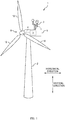
- Fig. 1 is a schematic perspective view of a wind power generator 1.
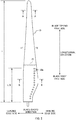
- Fig. 2 is a plan view of a windmill blade 10.
- Fig. 3A is a diagram describing an airflow around a section of a windmill blade 10 along line A-A in Fig. 2 .
- Fig. 3B is a diagram describing an airflow around a section of a windmill blade 10 along line B-B in Fig. 2 .
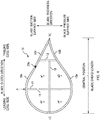
- Fig. 4 is a sectional view of a windmill blade 10 along line B-B in Fig. 2 .
- the wind power generator 1 includes a tower 2 installed on a base such as the ground, a nacelle 5 installed to a tip part of the tower 2 and housing such as a generator 3 and a rotary shaft 4 of the generator, a rotor 6 that has three lift-type windmill blades 10 and rotates around the rotary shaft 4 elongated in a horizontal direction, and an anemometer 7 attached to the nacelle 5.
- the windmill blades 10 are attached radially such that the longitudinal direction is along a radial direction of the rotary shaft 4.
- the wind power generator 1 of the present embodiment is a generator using a horizontal axis lift-type windmill.
- the wind power generator 1 may be a generator using a windmill in which a rotary shaft of the windmill blades is along a horizontal direction.
- the direction in which the rotary shaft 4 extends is not limited to a precise horizontal direction and includes a direction that is slightly misaligned.
- the number of the windmill blades 10 is not limited to three.
- a linear direction that connects a leading edge LE and a trailing edge TE of the windmill blade 10 is referred to as a "blade chord direction”
- a length of a line connecting the leading edge LE and the trailing edge TE is referred to as a “blade chord length”
- a direction that intersects a plane formed in the longitudinal direction and the blade chord direction of the windmill blades 10 namely, a direction perpendicular to a paper plane in Fig.
- blade thickness direction a length in the blade thickness direction from a blade suction surface 10a to a blade pressure surface 10b is referred to as a "blade thickness”
- blade root part a section on the rotary shaft 4 side in the longitudinal direction of the windmill blade 10
- blade tip end part a section on the rotary shaft 4 side in the longitudinal direction of the windmill blade 10
- the windmill blade 10 is formed such that the blade suction surface 10a and the blade pressure surface 10b form a streamline shape over an entire length in the longitudinal direction.
- the blade thickness becomes gradually thicker from the leading edge LE toward the trailing edge TE, and after the blade becomes thickest at a position P, the blade thickness becomes gradually thinner toward the trailing edge TE.
- the windmill blade 10 receives a combined airflow Vc of an airflow Vw that occurs naturally from wind and an airflow Vr that occurs from rotation of the windmill blade 10.
- an angle of attack ⁇ that is an angle formed by the direction of the combined airflow Vc and the blade chord direction becomes larger, the lift of the windmill blade 10 increases, and the rotational force of the windmill blade 10 increases.
- the angle of attack ⁇ is equal to or greater than a predetermined angle, however, airflow does not flow along the blade suction surface 10a, and a boundary layer separation phenomenon in which airflow separates from the blade suction surface 10a occurs, and the lift of the windmill blade 10 decreases.
- a pitch control that adjusts an attachment angle (pitch angle) of the windmill blades 10 such that the windmill blades 10 are connected rotatably with respect to the rotary shaft 4 and an optimal angle of attack ⁇ is made according to wind direction and wind speed
- a yaw control to change the direction of the rotor 6 (the nacelle 35) according to the wind direction such that the rotor 6 can receive wind from the front are performed.
- pitch control and yaw control cannot cope with this situation, and there is a problem that a boundary layer separation phenomenon in the blade suction surface 10a occurred frequently.
- the blade root part ( Fig. 3B ) of the windmill blade 10 has a slower rotational speed compared to the blade tip end part ( Fig. 3A ), and the speed of airflow Vr due to the rotation of the windmill blade 10 is slow.
- the blade root part has a greater angle of attack ⁇ compared to the blade tip end part, and the pitch control cannot cope with this situation.
- the ratio of decrease in speed (Vc' ⁇ Vc) of the combined airflow is large due to the decrease in speed of natural wind (Vw' ⁇ Vw), the wind speed easily decreases, and the boundary layer separation phenomenon easily occurs.
- the boundary layer separation phenomenon easily occurs in the blade root part, and the blade root part has a section with a large curvature compared to the blade tip end part with a thin blade thickness. This also makes the boundary layer separation phenomenon occur easily in the blade suction surface 10a in the blade root part compared to the blade tip end part.
- the object is to suppress damage to the windmill blade 10 due to the boundary layer separation phenomenon occurring in the blade suction surface 10a, in particular, to suppress damage to the windmill blade 10 due to a boundary layer separation phenomenon that easily occurs in the blade root part.
- openable and closable apertures 20a that connect the closed space in the windmill blade 10 and the outside are provided.
- the apertures 20a are opened, and after the boundary layer separation phenomenon has resolved, or after a predetermined time has passed from when the apertures have opened, or after a predetermined time has passed after the boundary layer separation phenomenon has resolved, the apertures 20a are closed.
- airflow can be made to flow from the closed space in the windmill blade 10 via the apertures 20a, toward the negative pressure region of the blade suction surface 10a generated due to the boundary layer separation phenomenon.
- pressure in the negative region of the blade suction surface 10a can be increased, and pressure of the space in the blade can be decreased.
- turbulent flow caused by depressions and projections (for example, edges of the depressions or lid members) in the apertures 20a can stop the boundary layer separation phenomenon or decrease influence of the boundary layer separation phenomenon.
- the apertures 20 are closed, and thus the flow of airflow between the space in the blade and the blade suction surface 10a can be prevented, and forming of the turbulent flow caused by the depressions and projections in the apertures 20a can be prevented.
- airflow can be made to flow along the blade suction surface 10a, and the windmill blade 10 can be rotated efficiently.
- the apertures 20a are provided in a section on the blade root part side (a section to the rotary shaft 4 side in the longitudinal direction) of the blade suction surface 10a. Specifically, a plurality of the apertures 20a are aligned with an interval in the longitudinal direction, over a range of 1/3 of a length (L/3) of an entire length (L) of the windmill blade 10 from an end on the blade root part side of the windmill blade 10 toward the blade tip end part side.
- a region to the downstream side of the separation point of the blade suction surface 10a becomes a negative pressure region.
- the apertures 20a are provided in a section on the trailing edge side than the thickest blade position P of the blade suction surface 10a. Furthermore, the apertures 20a are provided in a section on the trailing edge side than the central position of the blade chord length of the blade suction surface 10a.
- the apertures 20a are easily positioned in a position to a negative pressure region that is formed due to the boundary layer separation phenomenon.
- the airflow can be certainly made to flow from the space in the blade toward the negative pressure region and efficiently, and the pressure difference between the space in the blade and above the blade suction surface 10a can be made small.
- a hole 14 is provided in the first reinforcement member 11 in a section near to the blade suction surface side than the first partition wall 13, the hole connecting a space a2 in the blade on the leading edge side than the first reinforcement member 11 and a space a1 in the blade on the trailing edge side.
- the pressure in the spaces a3, a4 in the blade to the blade pressure surface side can be prevented from decreasing to lower than the outside pressure and a force applying to the blade pressure surface 10b can be prevented, thus being able to suppress damage to the windmill blade 10.
- a second partition wall 15 is provided in the windmill blade 10.
- the second partition wall 15 divides the closed space in the windmill blade 10 in the longitudinal direction to a space in which the apertures 20a are not provided to the blade suction surface 10a (a space to the blade tip end part side) and a space provided with the apertures 20a in the blade suction surface 10a (a space to the blade root part side).
- the second partition wall 15 by providing the second partition wall 15 in the windmill blade 10, the flow of air between the space on the blade tip end part side and the space on the blade root part side is restricted, and even when the apertures 20a are opened, the pressure of the space to the blade tip end part side can be prevented from decreasing to lower than the outside pressure.
- a force can be prevented from applying to the outer peripheral surface of the blade tip end part, and damage to the windmill blade 10 can be suppressed.
- the first reinforcement member 11 is provided with a hole 14 that connects the space a2 in the blade on the leading edge side of the windmill blade 10 than the first reinforcement member 11 and the space a1 in the blade on the trailing edge side, near to the blade suction surface side than the first partition wall 13.
Landscapes
- Engineering & Computer Science (AREA)
- Life Sciences & Earth Sciences (AREA)
- Sustainable Development (AREA)
- Sustainable Energy (AREA)
- Chemical & Material Sciences (AREA)
- Combustion & Propulsion (AREA)
- Mechanical Engineering (AREA)
- General Engineering & Computer Science (AREA)
- Physics & Mathematics (AREA)
- Fluid Mechanics (AREA)
- Wind Motors (AREA)
Abstract
Description
- The present invention relates to wind power generators.
- With a wind power generator including lift-type windmill blades, when speed of air current flowing along a blade suction surface is faster than speed of air current flowing along a blade pressure surface, lift toward the blade suction surface is formed. With this lift the windmill blades rotate to drive a generator, and the wind power energy is converted to obtain electric energy. As the lift increases in proportion to the speed of airflow forming in the periphery of the wind blade surface, for example, there has been proposed a wind power generator provided with vortex generating sections on a blade suction surface of windmill blades, to prevent decrease in speed of airflow due to friction with the blade suction surface (for example, refer to PTL 1).
- PTL 1: Patent Application Laid-open Publication No.
2009-127448 - Further, the lift that is formed on the blade suction surface of the windmill blade increases as an angle of attack that is an angle formed by a linear direction (a blade chord direction) that connects a leading edge and a trailing edge of the windmill blade and a direction of wind that the wind blade receives becomes greater. When the angle of attack becomes equal to or greater than a predetermined angle, however, a boundary layer separation phenomenon in which airflow separates from a blade suction surface occurs and the lift of the windmill blade decreases. Further, when the boundary layer separation phenomenon occurs in the blade suction surface, a negative pressure region is formed in a downstream side of the separation point, and a difference in pressure is formed between the space in the blades and on the blade suction surface, and a force pulling the blade suction surface to the outer side is applied to the blade suction surface. As a result, the blade suction surface deforms, a fracture is formed in a leading edge of the windmill blade, and the like, and the windmill blade is damaged.
- This invention has been made in view of the above matters, and an object is to suppress damage to a windmill blade due to a boundary layer separation phenomenon that occurs on a blade suction surface of the windmill blade.
- An aspect of this invention to achieve the above object is a wind power generator in which a rotor including lift-type windmill blades receives wind and rotates, to drive a generator to generate electric power, the wind power generator including: at least one aperture that connects a closed space in the windmill blade and an outside of the windmill blade, provided on a blade suction surface of the windmill blade, the aperture being openable and closable.
- With this wind power generator, airflow can be made to flow from the closed space in the windmill blade, toward a negative pressure region on the blade suction surface which has formed with the boundary layer separation phenomenon. Thus, the pressure of the negative pressure region on the blade suction surface increases, and the pressure in the space in the blade decreases, decreasing a pressure difference between the two and decreasing a force that applies to the blade suction surface. Thus, damage to the windmill blade can be suppressed. Further, the boundary layer separation phenomenon may be stopped due to forming of turbulent flows caused by a depression and a projection (for example, an edge of the depression and a lid member) in the aperture, and influence of the boundary layer separation phenomenon can be decreased. Further, when the boundary layer separation phenomenon is not occurring on the blade suction surface the aperture is closed, thus the flow of airflow between the space in the blade and the blade suction surface can be prevented. Further, the turbulent flows caused by the depression and the projection in the aperture can be prevented from occurring. Thus, the airflow can be made to flow along the blade suction surface, and the windmill blades can be rotated efficiently.
- The wind power generator, wherein when a boundary layer separation phenomenon or a precursory phenomenon thereof occurs on the blade suction surface, the aperture is opened, and after the boundary layer separation phenomenon has resolved, or after a predetermined time has passed from when the aperture has opened, or after a predetermined time has passed after the boundary layer separation phenomenon has resolved, the aperture is closed.
- With this wind power generator, the airflow can be made to flow from the closed space in the windmill blade toward the negative pressure region on the blade suction surface that has formed with the boundary layer separation phenomenon, and damage to the windmill blade can be suppressed. Further, boundary layer separation phenomenon may be stopped due to forming of the turbulent flows caused by the depression and the projection (for example, an edge of the depression and the lid member) in the aperture, and influence of the boundary layer separation phenomenon may be decreased. Further, when the boundary layer separation phenomenon is not occurring on the blade suction surface, by preventing the flow of airflow between the space in the blade and the blade suction surface, and by preventing occurring of turbulent flows caused by the depression and projection in the aperture, the airflow can be made to flow along the blade suction surface. Thus, the windmill blade can be efficiently rotated.
- The wind power generator, wherein a partition wall that divides the closed space in the windmill blade into a space on the blade suction surface side and a space on the blade pressure surface side is provided in the closed space.
- With this wind power generator, when the aperture opens, the pressure in the space in the blade on the blade pressure surface side decreasing and combining with pressure of wind blowing on the blade pressure surface and applying a force to destroy the blade can be suppressed, and damage to the windmill blade can be suppressed.
- The wind power generator, wherein a rotary shaft of the rotor extends in a horizontal direction, and the windmill blades are attached radially such that a longitudinal direction of the windmill blades is along a radial direction of the rotary shaft, and the aperture is provided in a section, of the blade suction surface, on the rotary shaft side in the longitudinal direction.
- With this wind power generator, damage to the section to the blade root part side (the rotary shaft side) in which the boundary layer separation phenomenon easily occurs can be certainly suppressed.
- The wind power generator, wherein a partition wall that divides the closed space in the windmill blade in the longitudinal direction is provided in the closed space, the partition wall dividing the closed space into a space in which the aperture is provided in the blade suction surface and a space in which the aperture is not provided in the blade suction surface.
- With this wind power generator, when the apertures open, the pressure decreasing in the space not provided with apertures (a space to the blade tip end part side) on the blade suction surface and a force applying on the outer circumferential surface of the windmill blade can be suppressed, and damage to the windmill blade can be suppressed.
- The wind power generator, wherein the aperture is provided in a section nearer to a trailing edge side than a position where a blade thickness from the blade suction surface to the blade pressure surface is thickest, of the blade suction surface.
- With this wind power generator, the apertures can be easily positioned in the position of the negative pressure region formed with the boundary layer separation phenomenon, and the airflow can be made to flow from the space in the blade toward the negative pressure region, certainly and efficiently, and the pressure difference between the space in the blade and above the blade suction surface can be made small.
- The wind power generator, wherein the aperture is provided in a section nearer to a leading edge side than a position where the blade thickness is thickest, of the blade suction surface.
- With this wind power generator, even when the negative pressure region due to the boundary layer separation phenomenon is formed on the leading edge side of the blade suction surface, damage to the windmill blade can be suppressed. Further, by opening the apertures on the leading edge side and the trailing edge side simultaneously, a large amount of airflow can be made to flow continuously toward the negative pressure region, and the pressure difference between the space in the blade and above the blade suction surface can be made small more certainly.
- The wind power generator, wherein a reinforcement member that extends from a suction side member forming the blade suction surface to a pressure side member forming the blade pressure surface is provided in the closed space, and a hole that connects a space on the leading edge side of the windmill blade than the reinforcement member and a space on the trailing edge side of the windmill blade than the reinforcement member is provided in the reinforcement member.
- With this wind power generator, even when the negative pressure region due to the boundary layer separation phenomenon is formed on the leading edge side of the blade suction surface, the pressure difference between the space in the blade on the leading edge side and above the blade suction surface can be made small, and damage to the windmill blade can be suppressed. Further, a large amount of airflow can be made to flow from the larger space in the blade toward the negative pressure region, and the pressure difference between the space in the blade and the blade suction surface can be made small more certainly.
- Other features of this invention will become clear from the attached drawings and descriptions in this specification.
- According to this invention, damage to a windmill blade due to a boundary layer separation phenomenon that occurs on a blade suction surface of the windmill blade can be suppressed.
-
- [
Fig. 1] Fig. 1 is a schematic perspective view of a wind power generator. - [
Fig. 2] Fig. 2 is a plan view of a windmill blade. - [
Fig. 3A] Fig. 3A is a diagram describing an airflow around a windmill blade in section along line A-A inFig. 2 . - [
Fig. 3B] Fig. 3B is a diagram describing an airflow around a windmill blade in section along line B-B inFig. 2 . - [
Fig. 4] Fig. 4 is a sectional view of a windmill blade along line B-B inFig. 2 . - [
Fig. 5A] Fig. 5A is a diagram describing an aperture unit provided to a blade suction surface. - [
Fig. 5B] Fig. 5B is a diagram describing an aperture unit provided to a blade suction surface. - [
Fig. 5C] Fig. 5C is a diagram describing an aperture unit provided to a blade suction surface. - [
Fig. 5D] Fig. 5D is a diagram describing an aperture unit provided to a blade suction surface. - [
Fig. 6] Fig. 6 is a diagram describing a modified example of a windmill blade. -
Fig. 1 is a schematic perspective view of a wind power generator 1.Fig. 2 is a plan view of awindmill blade 10.Fig. 3A is a diagram describing an airflow around a section of awindmill blade 10 along line A-A inFig. 2 .Fig. 3B is a diagram describing an airflow around a section of awindmill blade 10 along line B-B inFig. 2 .Fig. 4 is a sectional view of awindmill blade 10 along line B-B inFig. 2 . - The wind power generator 1 includes a
tower 2 installed on a base such as the ground, anacelle 5 installed to a tip part of thetower 2 and housing such as agenerator 3 and arotary shaft 4 of the generator, arotor 6 that has three lift-type windmill blades 10 and rotates around therotary shaft 4 elongated in a horizontal direction, and ananemometer 7 attached to thenacelle 5. Thewindmill blades 10 are attached radially such that the longitudinal direction is along a radial direction of therotary shaft 4. In other words, the wind power generator 1 of the present embodiment is a generator using a horizontal axis lift-type windmill. It is not limited to the above, however, and, for example the wind power generator 1 may be a generator using a windmill in which a rotary shaft of the windmill blades is along a horizontal direction. Further, the direction in which therotary shaft 4 extends is not limited to a precise horizontal direction and includes a direction that is slightly misaligned. Further, the number of thewindmill blades 10 is not limited to three. - In the below description, a linear direction that connects a leading edge LE and a trailing edge TE of the
windmill blade 10 is referred to as a "blade chord direction", a length of a line connecting the leading edge LE and the trailing edge TE is referred to as a "blade chord length", a direction that intersects a plane formed in the longitudinal direction and the blade chord direction of the windmill blades 10 (namely, a direction perpendicular to a paper plane inFig. 2 ) is referred to as a "blade thickness direction", a length in the blade thickness direction from ablade suction surface 10a to ablade pressure surface 10b is referred to as a "blade thickness", a section on therotary shaft 4 side in the longitudinal direction of thewindmill blade 10 is referred to as a "blade root part" and the opposite side section is referred to as a "blade tip end part". - The
windmill blade 10 is formed such that theblade suction surface 10a and theblade pressure surface 10b form a streamline shape over an entire length in the longitudinal direction. In more detail, as shown inFig. 4 , the blade thickness becomes gradually thicker from the leading edge LE toward the trailing edge TE, and after the blade becomes thickest at a position P, the blade thickness becomes gradually thinner toward the trailing edge TE. It should be noted that, with thewindmill blade 10 of this embodiment, a circumferential edge of asuction side member 101 forming theblade suction surface 10a and a circumferential edge of apressure side member 102 forming theblade pressure surface 10b are joined by such as welding, and a closed space is formed inside thewindmill blade 10 with thesuction side member 101 and thepressure side member 102. Further, as shown inFig. 2 , in thewindmill blade 10, the blade chord length gradually decreases and the blade thickness is made thinner from the blade root part toward the blade tip end part. - When the
windmill blade 10 receives wind, and an airflow flows from the leading edge LE to the trailing edge TE of thewindmill blade 10, a lift toward an outer side of theblade suction surface 10a is generated due to a speed difference between airflows in theblade suction surface 10a side and theblade pressure surface 10b side. As a result, the windmill blade 10 (the rotor 6) rotates with therotary shaft 4, and the rotational force of therotary shaft 4 is transmitted to thegenerator 3, and thegenerator 3 is driven to generate electric power. - As shown in
Fig. 3 , thewindmill blade 10 receives a combined airflow Vc of an airflow Vw that occurs naturally from wind and an airflow Vr that occurs from rotation of thewindmill blade 10. As an angle of attack α that is an angle formed by the direction of the combined airflow Vc and the blade chord direction becomes larger, the lift of thewindmill blade 10 increases, and the rotational force of thewindmill blade 10 increases. When the angle of attack α is equal to or greater than a predetermined angle, however, airflow does not flow along theblade suction surface 10a, and a boundary layer separation phenomenon in which airflow separates from theblade suction surface 10a occurs, and the lift of thewindmill blade 10 decreases. - Thus, in the wind power generator, for example, such as a pitch control that adjusts an attachment angle (pitch angle) of the
windmill blades 10 such that thewindmill blades 10 are connected rotatably with respect to therotary shaft 4 and an optimal angle of attack α is made according to wind direction and wind speed, and a yaw control to change the direction of the rotor 6 (the nacelle 35) according to the wind direction such that therotor 6 can receive wind from the front are performed. But, for example, in a region where the wind direction and wind speed changes greatly, such as in a mountainous region of Japan, pitch control and yaw control cannot cope with this situation, and there is a problem that a boundary layer separation phenomenon in theblade suction surface 10a occurred frequently. - In particular, the blade root part (
Fig. 3B ) of thewindmill blade 10 has a slower rotational speed compared to the blade tip end part (Fig. 3A ), and the speed of airflow Vr due to the rotation of thewindmill blade 10 is slow. Thus, the blade root part has a greater angle of attack α compared to the blade tip end part, and the pitch control cannot cope with this situation. Additionally, since the ratio of decrease in speed (Vc' → Vc) of the combined airflow is large due to the decrease in speed of natural wind (Vw' → Vw), the wind speed easily decreases, and the boundary layer separation phenomenon easily occurs. Further, since the blade root part with slow rotational speed has a low Reynolds number compared to the blade tip end part, and a laminar boundary layer is formed in the periphery of the blade root part, the boundary layer separation phenomenon easily occurs in the blade root part, and the blade root part has a section with a large curvature compared to the blade tip end part with a thin blade thickness. This also makes the boundary layer separation phenomenon occur easily in theblade suction surface 10a in the blade root part compared to the blade tip end part. - When the boundary layer separation phenomenon occurs in the
blade suction surface 10a, other than the lift decreasing, as shown inFig. 3B , a pressure above theblade suction surface 10a to a downstream side of the boundary layer separation phenomenon decreases, and a negative pressure region is generated. Thus, a pressure difference between the space in the blade and above the blade suction surface occurs, and a force pulling theblade suction surface 10a to the outer side is applied to theblade suction surface 10a (the suction side member 101). Then, an outer shape of theblade suction surface 10a deforms, or a fracture forms in a leading edge LE section of thewindmill blade 10 in which thesuction side member 101 and thepressure side member 102 are joined as in this embodiment, and there is a possibility that thewindmill blade 10 is damaged. With the wind power generator 1 of this embodiment, the object is to suppress damage to thewindmill blade 10 due to the boundary layer separation phenomenon occurring in theblade suction surface 10a, in particular, to suppress damage to thewindmill blade 10 due to a boundary layer separation phenomenon that easily occurs in the blade root part. - To suppress damage of the
windmill blade 10 due to the boundary layer separation phenomenon, in the wind power generator 1 of this embodiment, openable andclosable apertures 20a (anaperture unit 20 to be described later) that connect the closed space in thewindmill blade 10 and the outside are provided. When the boundary layer separation phenomenon in theblade suction surface 10a of thewindmill blade 10 or the precursory phenomenon thereof occurs, theapertures 20a are opened, and after the boundary layer separation phenomenon has resolved, or after a predetermined time has passed from when the apertures have opened, or after a predetermined time has passed after the boundary layer separation phenomenon has resolved, theapertures 20a are closed. - By doing so, airflow can be made to flow from the closed space in the
windmill blade 10 via theapertures 20a, toward the negative pressure region of theblade suction surface 10a generated due to the boundary layer separation phenomenon. Thus, pressure in the negative region of theblade suction surface 10a can be increased, and pressure of the space in the blade can be decreased. In other words, since the pressure difference between the space in the blade and above theblade suction surface 10a can be made small, and a force pulling theblade suction surface 10a to the outer side can be decreased, damage to thewindmill blade 10 can be suppressed. Further, turbulent flow caused by depressions and projections (for example, edges of the depressions or lid members) in theapertures 20a can stop the boundary layer separation phenomenon or decrease influence of the boundary layer separation phenomenon. On the other hand, when the boundary layer separation phenomenon is not occurring in theblade suction surface 10a, theapertures 20 are closed, and thus the flow of airflow between the space in the blade and theblade suction surface 10a can be prevented, and forming of the turbulent flow caused by the depressions and projections in theapertures 20a can be prevented. Thus, airflow can be made to flow along theblade suction surface 10a, and thewindmill blade 10 can be rotated efficiently. - Further, as described above, the boundary layer separation phenomenon in the
blade suction surface 10a easily occurs in the blade root part of thewindmill blade 10 than in the blade tip end part. For this reason, with thewindmill blade 10 of this embodiment, as shown inFig. 2 , theapertures 20a are provided in a section on the blade root part side (a section to therotary shaft 4 side in the longitudinal direction) of theblade suction surface 10a. Specifically, a plurality of theapertures 20a are aligned with an interval in the longitudinal direction, over a range of 1/3 of a length (L/3) of an entire length (L) of thewindmill blade 10 from an end on the blade root part side of thewindmill blade 10 toward the blade tip end part side. On the other hand,apertures 20a are not provided in a section of theblade suction surface 10a on the blade tip end part side. This is because the boundary layer separation phenomenon does not easily occur in the blade tip end part as compared in the blade root part and there is little possibility of damage to thewindmill blade 10 due to the boundary layer separation phenomenon even without providingapertures 20a, and there is no problem in this. In other words, by providing theapertures 20a in only the section to the blade root part side of theblade suction surface 10a, in which the boundary layer separation phenomenon easily occurs, the number of theapertures 20a can be kept small, thereby increasing manufacturing cost of thewindmill blade 20 and suppressing decrease in strength of the windmill blade while certainly suppressing damage to thewindmill blade 10 due to the boundary layer separation phenomenon. It should be noted that, inFig. 2 , the plane shape of theaperture 20a is circular, but it is not limited to the above, and the plane shape may be such as a quadrangle, for example. - Further, a region to the downstream side of the separation point of the
blade suction surface 10a becomes a negative pressure region. In the case where a curvature of the section of the blade root part is large as in thewindmill blade 10 shown inFig. 4 , since the inclination directions of theblade suction surface 10a greatly differ on both sides of the thickest blade position P, the boundary layer separation phenomenon easily occurs near the thickest blade position P. For this reason, with thewindmill blade 10 of this embodiment, theapertures 20a are provided in a section on the trailing edge side than the thickest blade position P of theblade suction surface 10a. Furthermore, theapertures 20a are provided in a section on the trailing edge side than the central position of the blade chord length of theblade suction surface 10a. By doing so, theapertures 20a are easily positioned in a position to a negative pressure region that is formed due to the boundary layer separation phenomenon. Thus, the airflow can be certainly made to flow from the space in the blade toward the negative pressure region and efficiently, and the pressure difference between the space in the blade and above theblade suction surface 10a can be made small. - Further, as shown in
Fig. 4 , in thewindmill blade 10, a first reinforcement member 11 is provided at the thickest blade position P, and asecond reinforcement member 12 is provided at a position on the trailing edge side than theapertures 20a. Each of the first reinforcement member 11 and thesecond reinforcement member 12 is extended from an inner side surface of thesuction side member 101 to an inner side surface of thepressure side member 102 in the blade thickness direction. Afirst partition wall 13 that extends in the blade chord direction from thesecond reinforcement member 12 to an inner side surface corresponding to the leading edge LE is provided in thewindmill blade 10. Further, ahole 14 is provided in the first reinforcement member 11 in a section near to the blade suction surface side than thefirst partition wall 13, the hole connecting a space a2 in the blade on the leading edge side than the first reinforcement member 11 and a space a1 in the blade on the trailing edge side. - With the
first partition wall 13, the closed space in thewindmill blade 10 is divided into spaces a1, a2 in the blade on the blade suction surface side and spaces a3, a4 in the blade on the blade pressure surface side, and the flow of air between the spaces a1, a2 in the blade on the blade suction surface side and the spaces a3, a4 in the blade on the blade pressure surface side is restricted. In other words, with thefirst partition wall 13, the closed surface in thewindmill blade 10 is divided to the spaces a1, a2 in the blade that are connected to the outside above theblade suction surface 10a via theapertures 20a, and the spaces a3, a4 in the blade that are not connected to the outside above theblade suction surface 10a. Supposing that thefirst partition wall 13 is not provided in thewindmill blade 10, the pressure of the spaces a3, a4 in the blade on the blade pressure surface side will decrease when theapertures 20a open. But a negative pressure region is not formed in theblade pressure surface 10b as in theblade suction surface 10a. Thus, a difference in pressure is formedbetween the spaces a3, a4 in the blade to the blade pressure surface side and outside on the bladepressure surface side 10b, and a force to press the bladepressure surface side 10b to the inner side acts on theblade pressure surface 10b (the pressure side member 102), and theblade pressure surface 10b is deformed with such as a depression. Thus, by providing thefirst partition wall 13 in thewindmill blade 10, even when theapertures 20a open, the pressure in the spaces a3, a4 in the blade to the blade pressure surface side can be prevented from decreasing to lower than the outside pressure and a force applying to theblade pressure surface 10b can be prevented, thus being able to suppress damage to thewindmill blade 10. - Similarly, as shown in
Fig. 2 , asecond partition wall 15 is provided in thewindmill blade 10. Thesecond partition wall 15 divides the closed space in thewindmill blade 10 in the longitudinal direction to a space in which theapertures 20a are not provided to theblade suction surface 10a (a space to the blade tip end part side) and a space provided with theapertures 20a in theblade suction surface 10a (a space to the blade root part side). In other words, by providing thesecond partition wall 15 in thewindmill blade 10, the flow of air between the space on the blade tip end part side and the space on the blade root part side is restricted, and even when theapertures 20a are opened, the pressure of the space to the blade tip end part side can be prevented from decreasing to lower than the outside pressure. Thus, a force can be prevented from applying to the outer peripheral surface of the blade tip end part, and damage to thewindmill blade 10 can be suppressed. - The
first partition wall 13 and thesecond partition wall 15 are preferably formed with a flexible member. In this case, when theapertures 20a open and the pressure in the space connected with theapertures 20a decreases, thefirst partition wall 13 and thesecond partition wall 15 bend to prevent a strong force from being applied to a connection part between the inner side surface of thewindmill blade 10 and thepartition walls - Further, as described above, the first reinforcement member 11 is provided with a
hole 14 that connects the space a2 in the blade on the leading edge side of thewindmill blade 10 than the first reinforcement member 11 and the space a1 in the blade on the trailing edge side, near to the blade suction surface side than thefirst partition wall 13. By doing so, when theapertures 20a open, the pressure in the space a1 in the blade to the trailing edge side as well as the space a2 on the leading edge side can be decreased. Thus, when a negative pressure region due to a boundary layer separation phenomenon is generated on the leading edge side of theblade suction surface 10a, the difference in pressure between the space a2 in the blade on the leading edge side and above theblade suction surface 10a can be made small, and damage to thewindmill blade 10 can be suppressed. Further, by providing thehole 14 to the first reinforcement member 11, a large amount of airflow can be made to flow from the larger spaces a1, a2 in the blade toward the negative pressure region, and the difference in pressure can certainly be made smaller between the spaces a1, a2 in the blade and above theblade suction surface 10a. -
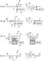
Fig. 5A to Fig. 5D are diagrams describing an embodiment of anaperture unit 20 provided to theblade suction surface 10a, namely, an opening and closing mechanism of theapertures 20a. It should be noted that, the actualblade suction surface 10a is a curved surface, but inFig. 5 theblade suction surface 10a is shown as a plane to simplify the description. Further, theaperture unit 20 shown inFig. 5 is merely one example, and the mechanism can be any mechanism as long as the mechanism can open and close theapertures 20a. - For example, the
aperture unit 20 shown inFig. 5A includes alid member 21 that is a part of thesuction side member 101, ahinge 22 that connects one end of thelid member 21 and thesuction side member 101, amotor 23 that rotationally moves thelid member 21 via thehinge 22, and acontroller 24 that controls themotor 23. In this case, when thecontroller 24 detects the boundary layer separation phenomenon or the precursory phenomenon thereof in theblade suction surface 10a, themotor 23 is driven to rotationally move thehinge 22. In this way, with thehinge 22 as a fulcrum, thelid member 21 is rotationally moved to the space a1 side in the blade to open theaperture 20a, and the space a1 in the blade and the outside above theblade suction surface 10a are connected. Further, thecontroller 24, after detecting that the boundary layer separation phenomenon has been resolved, or after a predetermined time has passed since theaperture 20a has been opened, or after a predetermined time has passed after detecting that the boundary layer separation phenomenon has been resolved, drives themotor 23 again to rotationally move thelid member 21 to close theaperture 20a, and shields connection between the space a1 in the blade and the outside above theblade suction surface 10a. - As shown in
Fig. 5B , there may be anaperture unit 20 including alid member 21 that is a part of asuction side member 101, amotor 23 with arotary shaft 23a connected to thelid member 21, and acontroller 24 that controls themotor 23. In this case, thecontroller 24 drives themotor 23, to rotationally move thelid member 21 around therotary shaft 23a of themotor 23, and theaperture 20a can be opened and closed. - Further, for example, as shown in
Fig. 5C , there may be anaperture unit 20 including alid member 21 that is a part of asuction side member 101, acontroller 24, ahousing 25 provided to a space a1 in the blade, anelectromagnetic solenoid 26 provided in thehousing 25, and aspring 27. It should be noted that, thelid member 21 includes alid part 21a covering anaperture 20a, an operatingshaft 21b that extends from a rear surface of thelid part 21a, and a lockingpart 21c that protrudes from the operatingshaft 21b. Thespring 27 is passed through the operatingshaft 21b that is below the lockingpart 21c. In this case, when thecontroller 24 excites a coil of theelectromagnetic solenoid 26, thelid member 21 is attracted to the side of the space a1 in the blade against a restoring force of thespring 27, to open theaperture 20a between thelid part 21a and thesuction side member 101. When thecontroller 24 demagnetizes the coil of theelectromagnetic solenoid 26, thelid member 21 is moved to the outer side with the restoring force of thespring 27, and theaperture 20a is closed with thelid part 21a. It should be noted that, when a ceiling part of thehousing 25 and the lockingpart 21c come into contact, the movement of thelid member 21 is restricted, and thelid part 21a and thesuction side member 101 are maintained in a flat state. - Further, an
aperture unit 20 shown inFig. 5D includes alid member 21 that is a part of asuction side member 101, ahinge 22 that connects an end of thelid member 21 and thesuction side member 101, and amagnet 28 provided in a position that comes in contact with another end (a rear surface) of thelid member 21. Theaperture 20a is opened and closed using a pressure difference between the space a1 in the blade and above theblade suction surface 10a. In this case, when a boundary layer separation phenomenon occurs on theblade suction surface 10a, thelid member 21 is pulled with the negative pressure region, and theaperture 20a is opened. Then, when the boundary layer separation phenomenon on theblade suction surface 10a is resolved, thelid member 21 is rotationally moved to the side of the space a1 in the blade due to thelid member 21's own weight or the attracting force of themagnet 28, and theaperture 20a is closed. - As with the
aperture unit 20 shown inFig. 5A to Fig. 5C described above, when thecontroller 24 is controlling opening and closing of theaperture 20a, thecontroller 24 needs to detect the boundary layer separation phenomenon. As described above, when the angle of attack α becomes too great, the boundary layer separation phenomenon occurs. Thus, for example, by calculating the angle of attack α based on the value measured by theanemometer 7, the boundary layer separation phenomenon can be detected. Specifically, thecontroller 24 can perform control to determine that the boundary layer separation phenomenon is occurring when the calculated angle of attack α is equal to or greater than a threshold value and make theaperture part 20a open, and thecontroller 24 can determine that the boundary layer separation phenomenon has resolved when the calculated angle of attack α is smaller than a threshold value and close theaperture part 20a. Further, to more accurately detect the boundary layer separation phenomenon, in the case of the wind power generator 1 performing pitch control or yaw control, the angle of attack α may be calculated in consideration of the attaching angle of thewindmills blade 10 and the orientation of therotor 6, in addition to the wind direction and the wind speed. - Further, when the boundary layer separation phenomenon occurs, the pressure on the
blade suction surface 10a decreases. Thus, a pressure sensor (not shown) that measures pressure above theblade suction surface 10a may be provided on theblade suction surface 10a, in order to detect occurrence and resolving of the boundary layer separation phenomenon based on the measurement value of the pressure sensor. Further, when the boundary layer separation phenomenon occurs, separation and re-contacting of airflow to theblade suction surface 10a are repeated, and vibration on theblade suction surface 10a occurs. Thus, a vibration sensor (not shown) that measures vibration on theblade suction surface 10a may be provided to theblade suction surface 10a, and the occurring and resolving of the boundary layer separation phenomenon may be detected based on measurement values of the vibration sensor. - Further, there are cases in which measurement values of such as wind direction and wind speed, pressure, and vibration change in a short period of time, and there is a possibility that the opening and closing of the
apertures 20a are repeated in a short period of time. For this reason, from when occurring of a boundary layer separation phenomenon has been detected with thecontroller 24 based on such as calculation results of an angle of attack α and theapertures 20a are opened, theapertures 20a may be closed after a predetermined time has passed. In other words, thecontroller 24 may close theaperture 20a without detecting resolving of the boundary layer separation phenomenon. In this case, control with thecontroller 24 also becomes easy. It should be noted that, the predetermined time from when theapertures 20a are opened to when theapertures 20a are closed is equal to or greater than a time needed from when theapertures 20a are opened to when there is no pressure difference between a space in the blade and above theblade suction surface 10a or when the pressure difference becomes small, and the time is to be decided based on such as calculation or experience. Further, theaperture 20a may be closed after a predetermined time has passed from when the boundary layer separation phenomenon has resolved. In this case, theaperture 20a can be closed after the boundary layer separation phenomenon has certainly been resolved, and further theapertures 20a are closed after detecting the resolving of the boundary layer separation phenomenon, thus damage to thewindmill blade 10 can be certainly suppressed. - Further, the boundary layer separation phenomenon does not have to be detected based on any one of the parameters of the angle of attack α, the pressure above the
blade suction surface 10a, and vibration. The boundary layer separation phenomenon may be detected based on a plurality of the parameters. Further, theaperture 20a may be opened at a timing in which a precursory phenomenon of the boundary layer separation phenomenon has been detected based on such as the angle of attack α, the pressure above theblade suction surface 10a, and vibration. - Further, in the section where the
apertures 20a have been provided which is a section on the blade root part side of theblade suction surface 10a, a plurality of pressure sensors and vibration sensors to detect the boundary layer separation phenomenon can be arranged with an interval in between in the longitudinal direction. Then, the position in which the negative pressure region is formed due to the boundary layer separation phenomenon in the longitudinal direction may be specified, and only theaperture 20a in the region in which the negative pressure region is occurring may be opened. In this way, airflow can be made to flow along theblade suction surface 10a in the section of theblade suction surface 10a where the boundary layer separation phenomenon has not occurred. -
Fig. 6 is a diagram describing a modified example of thewindmill blade 10, and is a section view of the blade root part. In the above described windmill blade 10 (Fig. 4 ), theapertures 20a are provided in only the section on the trailing edge side than the thickest blade position P of theblade suction surface 10a, but it is not limited to the above, and theapertures 20a may be provided in the section to the leading edge side than the blade thickest position P of theblade suction surface 10a, as in thewindmill blade 10 inFig. 6 . In this case, even when the negative pressure region due to the boundary layer separation phenomenon occurs on the leading edge side of theblade suction surface 10a, by opening theapertures 20a on the leading edge side, the pressure difference between the space a2 in the blade on the leading edge side and above theblade suction surface 10a can be made small. As a result, damage to thewindmill blade 10 can be suppressed. Further, when the negative pressure region is formed on the trailing edge side of theblade suction surface 10a, by opening theapertures 20a on the leading edge side and on the trailing edge side simultaneously, a large amount of airflow can be made to flow continuously toward the negative pressure region, and the pressure difference between the spaces a1, a2 in the blade and above theblade suction surface 10a can be made certainly small. - Further, in the above described
windmill blade 10, theapertures 20a are provided in only the section on the blade root part side of theblade suction surface 10a, but it is not limited to the above, and a windmill blade may be provided with theapertures 20a over an entire region of theblade suction surface 10a in the longitudinal direction, for example. Further, with the above-describedwindmill blade 10, thefirst partition wall 13 and thesecond partition wall 15 are provided in the space in the blade and thehole 14 is provided in the first reinforcement member 11, but the windmill does not have to be provided with the above. Further, the windmill may have oneaperture 20a. Further, the windmill may have a plurality (for example, three or more) ofapertures 20a aligned with an interval in between along a direction from the leading edge LE to the trailing edge TE of theblade suction surface 10a. - The above embodiment is to facilitate understanding of this invention and does not limit the invention in any way. This invention may be changed and modified without departing from the gist thereof, and equivalents of this invention are included.
-
- 1
- wind power generator,
- 2
- tower,
- 3
- generator,
- 4
- rotary shaft,
- 5
- nacelle,
- 6
- rotor,
- 7
- anemometer,
- 10
- windmill blade,
- 10a
- blade suction surface,
- 10b
- blade pressure surface,
- 101
- suction side member,
- 102
- pressure side member,
- 11
- first reinforcement member,
- 12
- second reinforcement member,
- 13
- first partition wall,
- 14
- hole,
- 15
- second partition wall,
- 20
- aperture unit,
- 20a
- aperture,
- 21
- lid member,
- 22
- hinge,
- 23
- motor,
- 24
- controller,
- 25
- housing,
- 26
- electromagnetic solenoid,
- 27
- spring,
- 28
- magnet
Claims (8)
- A wind power generator in which a rotor including lift-type windmill blades receives wind and rotates, to drive a generator to generate electric power, the wind power generator comprising:at least one aperture that connects a closed space in the windmill blade and an outside of the windmill blade, provided on a blade suction surface of the windmill blade, the aperture being openable and closable.
- The wind power generator according to claim 1, wherein
when a boundary layer separation phenomenon or a precursory phenomenon thereof occurs on the blade suction surface, the aperture is opened, and
after the boundary layer separation phenomenon has resolved, or after a predetermined time has passed from when the aperture has opened, or after a predetermined time has passed after the boundary layer separation phenomenon has resolved, the aperture is closed. - The wind power generator according to claim 1 or 2, wherein
a partition wall that divides the closed space in the windmill blade into a space on the blade suction surface side and a space on the blade pressure surface side is provided in the closed space. - The wind power generator according to any one of claims 1 to 3, wherein
a rotary shaft of the rotor extends in a horizontal direction, and the windmill blades are attached radially such that a longitudinal direction of the windmill blades is along a radial direction of the rotary shaft, and
the aperture is provided in a section, of the blade suction surface, on the rotary shaft side in the longitudinal direction. - The wind power generator according to claim 4, wherein
a partition wall that divides the closed space in the windmill blade in the longitudinal direction is provided in the closed space, the partition wall dividing the closed space into a space in which the aperture is provided in the blade suction surface and a space in which the aperture is not provided in the blade suction surface. - The wind power generator according to any one of claims 1 to 5, wherein
the aperture is provided in a section nearer to a trailing edge side than a position where a blade thickness from the blade suction surface to the blade pressure surface is thickest, of the blade suction surface. - The wind power generator according to claim 6, wherein
the aperture is provided in a section nearer to a leading edge side than a position where the blade thickness is thickest, of the blade suction surface. - The wind power generator according to any one of claims 1 to 7, wherein
a reinforcement member that extends from a suction side member forming the blade suction surface to a pressure side member forming the blade pressure surface is provided in the closed space, and
a hole that connects a space on the leading edge side of the windmill blade than the reinforcement member and a space on the trailing edge side of the windmill blade than the reinforcement member is provided in the reinforcement member.
Applications Claiming Priority (1)
| Application Number | Priority Date | Filing Date | Title |
|---|---|---|---|
| PCT/JP2014/055480 WO2015132884A1 (en) | 2014-03-04 | 2014-03-04 | Wind power generation device |
Publications (2)
| Publication Number | Publication Date |
|---|---|
| EP3115598A1 true EP3115598A1 (en) | 2017-01-11 |
| EP3115598A4 EP3115598A4 (en) | 2017-03-29 |
Family
ID=54054724
Family Applications (1)
| Application Number | Title | Priority Date | Filing Date |
|---|---|---|---|
| EP14884755.1A Withdrawn EP3115598A4 (en) | 2014-03-04 | 2014-03-04 | Wind power generation device |
Country Status (3)
| Country | Link |
|---|---|
| EP (1) | EP3115598A4 (en) |
| JP (1) | JP5886475B2 (en) |
| WO (1) | WO2015132884A1 (en) |
Cited By (3)
| Publication number | Priority date | Publication date | Assignee | Title |
|---|---|---|---|---|
| EP3798443A1 (en) * | 2019-09-24 | 2021-03-31 | Wobben Properties GmbH | Wind energy system |
| CN112639283A (en) * | 2018-08-30 | 2021-04-09 | 乌本产权有限公司 | Rotor blade, wind power plant and method for optimizing a wind power plant |
| US20230167800A1 (en) * | 2020-04-28 | 2023-06-01 | Lm Wind Power A/S | Wind turbine rotor blade with covered access window |
Families Citing this family (2)
| Publication number | Priority date | Publication date | Assignee | Title |
|---|---|---|---|---|
| US10240579B2 (en) * | 2016-01-27 | 2019-03-26 | General Electric Company | Apparatus and method for aerodynamic performance enhancement of a wind turbine |
| JP6154050B1 (en) | 2016-08-08 | 2017-06-28 | 三菱重工業株式会社 | Wind turbine blade, wind turbine rotor, wind power generator, and vortex generator mounting method |
Family Cites Families (17)
| Publication number | Priority date | Publication date | Assignee | Title |
|---|---|---|---|---|
| DE2944718A1 (en) * | 1979-11-06 | 1981-05-21 | Hans-Dietrich Ing.(grad.) 2000 Hamburg Goslich | ROTOR FOR LIGHTWEIGHT WIND TURBINES |
| DK174319B1 (en) * | 2000-06-20 | 2002-12-02 | Lm Glasfiber As | Wind turbine blade with noise canceling means |
| JP2003254226A (en) * | 2002-03-05 | 2003-09-10 | Ebara Corp | Device for reducing airflow noise of windmill |
| FR2846382B1 (en) * | 2003-02-12 | 2006-01-13 | Georges Boulisset | DEVICE FOR IMPROVING THE PERFORMANCE OF WINDMILL BLADES |
| DE10319246A1 (en) * | 2003-04-28 | 2004-12-16 | Aloys Wobben | Rotor blade of a wind turbine |
| EP1857671A1 (en) * | 2005-03-07 | 2007-11-21 | Intellectual Property Bank Corp. | Blade for vertical shaft windmill and lift type vertical shaft windmill |
| JP2007092716A (en) * | 2005-09-30 | 2007-04-12 | Toray Ind Inc | Wing structure and manufacturing method thereof |
| CN102165185B (en) * | 2008-08-29 | 2013-07-24 | 维斯塔斯风力系统有限公司 | Control system in wind turbine blades |
| US8267665B2 (en) * | 2008-09-25 | 2012-09-18 | The Boeing Company | Laminar flow rotor and related methods and systems |
| EP2253836A1 (en) * | 2009-05-18 | 2010-11-24 | Lm Glasfiber A/S | Wind turbine blade |
| US20110103950A1 (en) * | 2009-11-04 | 2011-05-05 | General Electric Company | System and method for providing a controlled flow of fluid to or from a wind turbine blade surface |
| US20110293421A1 (en) * | 2010-05-28 | 2011-12-01 | Lockheed Martin Corporation | Rotor blade having passive bleed path |
| US20110142595A1 (en) * | 2010-07-02 | 2011-06-16 | General Electric Company | Wind turbine blades with controlled active flow and vortex elements |
| JP2012163049A (en) * | 2011-02-07 | 2012-08-30 | Mitsubishi Heavy Ind Ltd | Wind turbine blade, and wind turbine generator including the same |
| US20120020803A1 (en) * | 2011-02-14 | 2012-01-26 | Paul Lees | Turbine blades, systems and methods |
| US9133819B2 (en) * | 2011-07-18 | 2015-09-15 | Kohana Technologies Inc. | Turbine blades and systems with forward blowing slots |
| JP5594740B2 (en) * | 2011-12-28 | 2014-09-24 | 株式会社日本製鋼所 | Wind power blade and wind power generator |
-
2014
- 2014-03-04 JP JP2015512412A patent/JP5886475B2/en active Active
- 2014-03-04 EP EP14884755.1A patent/EP3115598A4/en not_active Withdrawn
- 2014-03-04 WO PCT/JP2014/055480 patent/WO2015132884A1/en not_active Ceased
Cited By (6)
| Publication number | Priority date | Publication date | Assignee | Title |
|---|---|---|---|---|
| CN112639283A (en) * | 2018-08-30 | 2021-04-09 | 乌本产权有限公司 | Rotor blade, wind power plant and method for optimizing a wind power plant |
| US11459999B2 (en) * | 2018-08-30 | 2022-10-04 | Wobben Properties Gmbh | Rotor blade, wind turbine, and method for optimizing a wind turbine |
| CN112639283B (en) * | 2018-08-30 | 2024-04-30 | 乌本产权有限公司 | Rotor blade, wind power installation and method for optimizing a wind power installation |
| EP3798443A1 (en) * | 2019-09-24 | 2021-03-31 | Wobben Properties GmbH | Wind energy system |
| US11536248B2 (en) | 2019-09-24 | 2022-12-27 | Wobben Properties Gmbh | Wind power installation |
| US20230167800A1 (en) * | 2020-04-28 | 2023-06-01 | Lm Wind Power A/S | Wind turbine rotor blade with covered access window |
Also Published As
| Publication number | Publication date |
|---|---|
| WO2015132884A1 (en) | 2015-09-11 |
| EP3115598A4 (en) | 2017-03-29 |
| JPWO2015132884A1 (en) | 2017-03-30 |
| JP5886475B2 (en) | 2016-03-16 |
Similar Documents
| Publication | Publication Date | Title |
|---|---|---|
| CN102297080B (en) | Vortex generator assembly and the method for assembling wind turbine rotor blade | |
| KR101477213B1 (en) | Wind power generation system and control method thereof | |
| EP2497944B1 (en) | System and method of manipulating a boundary layer across a rotor blade of a wind turbine | |
| US8267653B2 (en) | System and method of operating an active flow control system to manipulate a boundary layer across a rotor blade of a wind turbine | |
| CN102933841B (en) | Wind turbine | |
| US8616846B2 (en) | Aperture control system for use with a flow control system | |
| EP2520799B1 (en) | Wind power generation system and control method for the same | |
| CN101321949A (en) | Blades for wind turbine rotors | |
| EP3115599A1 (en) | Wind power generation device | |
| WO2014207015A1 (en) | Rotor blade with noise reduction means | |
| JP5886475B2 (en) | Wind power generator | |
| EP2998571B1 (en) | Lift influencing device for a rotor blade of a wind turbine | |
| JP2013068221A (en) | Method and device for controlling revolution speed of blade by centrifugal force of the blade in vertical axis wind turbine | |
| JP2013137006A (en) | Wind power generation blade and wind power generation apparatus | |
| CN104736844A (en) | Wind turbine | |
| CN101784790A (en) | Windmill blade and wind power generation device using the windmill blade | |
| JP2014501357A (en) | Wind turbine with vertical axis | |
| KR20180017101A (en) | A rotor blade shaped to improve wake diffusion | |
| JP7477866B2 (en) | Wind turbine control device, wind turbine control program, and wind turbine control method | |
| EP2940292A1 (en) | Device for a rotor blade of a wind turbine | |
| EP3098436B1 (en) | Noise reducing flap with opening | |
| US20140169965A1 (en) | Wind turbine and the operation method of the same | |
| JP2010133416A (en) | Power-generating turbine in rotor-stator arrangement | |
| CN112639283A (en) | Rotor blade, wind power plant and method for optimizing a wind power plant | |
| JP6524396B2 (en) | Wave power generation turbine |
Legal Events
| Date | Code | Title | Description |
|---|---|---|---|
| STAA | Information on the status of an ep patent application or granted ep patent |
Free format text: STATUS: THE INTERNATIONAL PUBLICATION HAS BEEN MADE |
|
| PUAI | Public reference made under article 153(3) epc to a published international application that has entered the european phase |
Free format text: ORIGINAL CODE: 0009012 |
|
| STAA | Information on the status of an ep patent application or granted ep patent |
Free format text: STATUS: REQUEST FOR EXAMINATION WAS MADE |
|
| 17P | Request for examination filed |
Effective date: 20161004 |
|
| AK | Designated contracting states |
Kind code of ref document: A1 Designated state(s): AL AT BE BG CH CY CZ DE DK EE ES FI FR GB GR HR HU IE IS IT LI LT LU LV MC MK MT NL NO PL PT RO RS SE SI SK SM TR |
|
| AX | Request for extension of the european patent |
Extension state: BA ME |
|
| A4 | Supplementary search report drawn up and despatched |
Effective date: 20170227 |
|
| RIC1 | Information provided on ipc code assigned before grant |
Ipc: F03D 7/02 20060101ALI20170221BHEP Ipc: F03D 1/06 20060101AFI20170221BHEP |
|
| DAX | Request for extension of the european patent (deleted) | ||
| STAA | Information on the status of an ep patent application or granted ep patent |
Free format text: STATUS: THE APPLICATION IS DEEMED TO BE WITHDRAWN |
|
| 18D | Application deemed to be withdrawn |
Effective date: 20170927 |