EP3115263B1 - Rollover danger warning device - Google Patents
Rollover danger warning device Download PDFInfo
- Publication number
- EP3115263B1 EP3115263B1 EP15758162.0A EP15758162A EP3115263B1 EP 3115263 B1 EP3115263 B1 EP 3115263B1 EP 15758162 A EP15758162 A EP 15758162A EP 3115263 B1 EP3115263 B1 EP 3115263B1
- Authority
- EP
- European Patent Office
- Prior art keywords
- vehicle
- limit
- lateral rollover
- external force
- index
- Prior art date
- Legal status (The legal status is an assumption and is not a legal conclusion. Google has not performed a legal analysis and makes no representation as to the accuracy of the status listed.)
- Active
Links
- 238000001514 detection method Methods 0.000 claims description 77
- 238000005096 rolling process Methods 0.000 claims description 57
- 230000000052 comparative effect Effects 0.000 claims description 22
- 230000001133 acceleration Effects 0.000 description 57
- 230000010355 oscillation Effects 0.000 description 42
- 230000005484 gravity Effects 0.000 description 34
- 239000000725 suspension Substances 0.000 description 21
- 230000033001 locomotion Effects 0.000 description 17
- 238000012545 processing Methods 0.000 description 14
- 238000000034 method Methods 0.000 description 10
- 238000004364 calculation method Methods 0.000 description 8
- 230000006870 function Effects 0.000 description 8
- 230000035945 sensitivity Effects 0.000 description 6
- 230000008859 change Effects 0.000 description 4
- 230000008901 benefit Effects 0.000 description 3
- 238000002474 experimental method Methods 0.000 description 3
- 238000005259 measurement Methods 0.000 description 3
- 238000010586 diagram Methods 0.000 description 2
- 238000005516 engineering process Methods 0.000 description 2
- 230000010365 information processing Effects 0.000 description 2
- 238000005381 potential energy Methods 0.000 description 2
- 230000008569 process Effects 0.000 description 2
- 101100129500 Caenorhabditis elegans max-2 gene Proteins 0.000 description 1
- 230000005856 abnormality Effects 0.000 description 1
- 238000004458 analytical method Methods 0.000 description 1
- 238000013459 approach Methods 0.000 description 1
- 239000013078 crystal Substances 0.000 description 1
- 230000001419 dependent effect Effects 0.000 description 1
- 238000011161 development Methods 0.000 description 1
- 238000006073 displacement reaction Methods 0.000 description 1
- 238000009434 installation Methods 0.000 description 1
- 239000004973 liquid crystal related substance Substances 0.000 description 1
- 238000000926 separation method Methods 0.000 description 1
- 230000007306 turnover Effects 0.000 description 1
- 230000000007 visual effect Effects 0.000 description 1
- XLYOFNOQVPJJNP-UHFFFAOYSA-N water Substances O XLYOFNOQVPJJNP-UHFFFAOYSA-N 0.000 description 1
Images


Classifications
-
- B—PERFORMING OPERATIONS; TRANSPORTING
- B60—VEHICLES IN GENERAL
- B60R—VEHICLES, VEHICLE FITTINGS, OR VEHICLE PARTS, NOT OTHERWISE PROVIDED FOR
- B60R21/00—Arrangements or fittings on vehicles for protecting or preventing injuries to occupants or pedestrians in case of accidents or other traffic risks
- B60R21/01—Electrical circuits for triggering passive safety arrangements, e.g. airbags, safety belt tighteners, in case of vehicle accidents or impending vehicle accidents
- B60R21/013—Electrical circuits for triggering passive safety arrangements, e.g. airbags, safety belt tighteners, in case of vehicle accidents or impending vehicle accidents including means for detecting collisions, impending collisions or roll-over
- B60R21/0132—Electrical circuits for triggering passive safety arrangements, e.g. airbags, safety belt tighteners, in case of vehicle accidents or impending vehicle accidents including means for detecting collisions, impending collisions or roll-over responsive to vehicle motion parameters, e.g. to vehicle longitudinal or transversal deceleration or speed value
-
- B—PERFORMING OPERATIONS; TRANSPORTING
- B63—SHIPS OR OTHER WATERBORNE VESSELS; RELATED EQUIPMENT
- B63B—SHIPS OR OTHER WATERBORNE VESSELS; EQUIPMENT FOR SHIPPING
- B63B43/00—Improving safety of vessels, e.g. damage control, not otherwise provided for
-
- B—PERFORMING OPERATIONS; TRANSPORTING
- B60—VEHICLES IN GENERAL
- B60R—VEHICLES, VEHICLE FITTINGS, OR VEHICLE PARTS, NOT OTHERWISE PROVIDED FOR
- B60R16/00—Electric or fluid circuits specially adapted for vehicles and not otherwise provided for; Arrangement of elements of electric or fluid circuits specially adapted for vehicles and not otherwise provided for
- B60R16/02—Electric or fluid circuits specially adapted for vehicles and not otherwise provided for; Arrangement of elements of electric or fluid circuits specially adapted for vehicles and not otherwise provided for electric constitutive elements
- B60R16/023—Electric or fluid circuits specially adapted for vehicles and not otherwise provided for; Arrangement of elements of electric or fluid circuits specially adapted for vehicles and not otherwise provided for electric constitutive elements for transmission of signals between vehicle parts or subsystems
- B60R16/0231—Circuits relating to the driving or the functioning of the vehicle
- B60R16/0232—Circuits relating to the driving or the functioning of the vehicle for measuring vehicle parameters and indicating critical, abnormal or dangerous conditions
- B60R16/0233—Vehicle tilting, overturning or roll over
-
- B—PERFORMING OPERATIONS; TRANSPORTING
- B60—VEHICLES IN GENERAL
- B60W—CONJOINT CONTROL OF VEHICLE SUB-UNITS OF DIFFERENT TYPE OR DIFFERENT FUNCTION; CONTROL SYSTEMS SPECIALLY ADAPTED FOR HYBRID VEHICLES; ROAD VEHICLE DRIVE CONTROL SYSTEMS FOR PURPOSES NOT RELATED TO THE CONTROL OF A PARTICULAR SUB-UNIT
- B60W40/00—Estimation or calculation of non-directly measurable driving parameters for road vehicle drive control systems not related to the control of a particular sub unit, e.g. by using mathematical models
- B60W40/12—Estimation or calculation of non-directly measurable driving parameters for road vehicle drive control systems not related to the control of a particular sub unit, e.g. by using mathematical models related to parameters of the vehicle itself, e.g. tyre models
- B60W40/13—Load or weight
-
- G—PHYSICS
- G01—MEASURING; TESTING
- G01M—TESTING STATIC OR DYNAMIC BALANCE OF MACHINES OR STRUCTURES; TESTING OF STRUCTURES OR APPARATUS, NOT OTHERWISE PROVIDED FOR
- G01M1/00—Testing static or dynamic balance of machines or structures
- G01M1/12—Static balancing; Determining position of centre of gravity
- G01M1/122—Determining position of centre of gravity
-
- B—PERFORMING OPERATIONS; TRANSPORTING
- B60—VEHICLES IN GENERAL
- B60W—CONJOINT CONTROL OF VEHICLE SUB-UNITS OF DIFFERENT TYPE OR DIFFERENT FUNCTION; CONTROL SYSTEMS SPECIALLY ADAPTED FOR HYBRID VEHICLES; ROAD VEHICLE DRIVE CONTROL SYSTEMS FOR PURPOSES NOT RELATED TO THE CONTROL OF A PARTICULAR SUB-UNIT
- B60W40/00—Estimation or calculation of non-directly measurable driving parameters for road vehicle drive control systems not related to the control of a particular sub unit, e.g. by using mathematical models
- B60W40/12—Estimation or calculation of non-directly measurable driving parameters for road vehicle drive control systems not related to the control of a particular sub unit, e.g. by using mathematical models related to parameters of the vehicle itself, e.g. tyre models
- B60W40/13—Load or weight
- B60W2040/1315—Location of the centre of gravity
-
- B—PERFORMING OPERATIONS; TRANSPORTING
- B60—VEHICLES IN GENERAL
- B60W—CONJOINT CONTROL OF VEHICLE SUB-UNITS OF DIFFERENT TYPE OR DIFFERENT FUNCTION; CONTROL SYSTEMS SPECIALLY ADAPTED FOR HYBRID VEHICLES; ROAD VEHICLE DRIVE CONTROL SYSTEMS FOR PURPOSES NOT RELATED TO THE CONTROL OF A PARTICULAR SUB-UNIT
- B60W2300/00—Indexing codes relating to the type of vehicle
- B60W2300/14—Tractor-trailers, i.e. combinations of a towing vehicle and one or more towed vehicles, e.g. caravans; Road trains
-
- B—PERFORMING OPERATIONS; TRANSPORTING
- B63—SHIPS OR OTHER WATERBORNE VESSELS; RELATED EQUIPMENT
- B63B—SHIPS OR OTHER WATERBORNE VESSELS; EQUIPMENT FOR SHIPPING
- B63B39/00—Equipment to decrease pitch, roll, or like unwanted vessel movements; Apparatus for indicating vessel attitude
- B63B39/14—Equipment to decrease pitch, roll, or like unwanted vessel movements; Apparatus for indicating vessel attitude for indicating inclination or duration of roll
Definitions
- the present invention relates to a lateral rollover risk warning device that reports the risk that a vehicle may be rolled over laterally.
- the present inventor has proposed a technique that uses the 3-D center-of-gravity detection theory to calculate a limit center-of-gravity height beyond which a structure will be rolled over laterally, as the lateral rollover limit height, thereby determining the lateral rollover risk of a structure for which the weight or the weight distribution has not been clarified in advance, on the basis of the lateral rollover limit height that has been calculated.
- the lateral rollover risk warning device of the present invention is a lateral rollover risk warning device that is installed in a vehicle that is supported by spring structures on both sides in the right-left direction across a vehicle axis of a vehicle body, respectively, reporting the risk of the vehicle being rolled over
- the lateral rollover risk warning device including: a vertical direction physical amount detection means for detecting an external force applied in the vertical direction of the vehicle body; a rotational direction physical amount detection means for detecting a rotation around the vehicle axis of the vehicle body; a limit condition calculating means that uses the results of detection by the vertical direction physical amount detection means and the rotational direction physical amount detection means to calculate a combination of the traveling speed and the horizontal direction deflection angle with which the vehicle is led to a rollover, as a limit condition; a traveling information receiving means that receives either or both of the traveling speed and the horizontal direction deflection angle from the vehicle in real time as a piece of traveling information; and a reporting means that uses the limit condition and the piece of traveling information to report
- the external force detector 10 is installed at the center in the right-left direction of the cargo bed 2, and the data processing apparatus 20 is installed in a driver's seat 5.
- the installation location of the external force detector 10 is not limited to the cargo bed 2, provided that the external force detector 10 is installed in the vehicle body of the vehicle 1 that is supported by the elastic forces.
- the external force detector 10 may be disposed in the tractor.
- the external force detector 10 may be installed in a location that is away from the center to a certain degree, being displaced forward or backward, or rightward or leftward, within a range in which there occurs no problem of a wrong detection for motions affected by another axis.
- the external force detector 10 includes a first acceleration sensor 11, an angular velocity sensor 12, a second acceleration sensor 13, and an A-D converter 14.
- the first acceleration sensor 11 the sensitivity axis is adjusted such that the acceleration in the up-down (self-weight) direction (the Z-axis direction shown in Figure 1 and Figure 2 ), in other words, the vertical oscillation of the cargo bed 2 in the up-down direction is detected.
- the angular velocity sensor 12 the sensitivity axis is adjusted such that the angular velocity in a direction of rotation around the vehicle axis 6.
- the direction of rotation around the vehicle axis 6 is referred to as the rolling direction.
- the second acceleration sensor 13 the sensitivity axis is adjusted such that the acceleration in the right and left direction (the X-axis direction shown in Figure 2 ), in other words, the external force in the right-left direction that is applied to the cargo bed 2 is detected.
- the first acceleration sensor 11, the angular velocity sensor 12, and the second acceleration sensor 13 are not particularly limited, and, for example, a crystal tuning fork type sensor or an oscillation type sensor may be used, and as the first acceleration sensor 11, the angular velocity sensor 12, and the second acceleration sensor 13, a three-axis (three dimensional) acceleration/angular velocity sensor may also be used.
- the A-D converter 14 converts analog signals (detection results) outputted from the first acceleration sensor 11, the angular velocity sensor 12, and the second acceleration sensor 13 into digital signals to output them to the data processing apparatus 20.
- an angular velocity sensor that detects a yaw angular velocity is installed horizontally, and with the detection result obtained, a trigonometric function may be used to determine the acceleration in the right-left direction.
- the data processing apparatus 20 is an information processing apparatus, such as a personal computer, and generates a piece of lateral rollover risk warning information on the basis of the result of detection that has been performed by the external force detector 10.
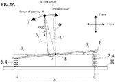
- the vehicle body of the vehicle 1 When the vehicle 1 is traveled, the vehicle body of the vehicle 1 will make an oscillation (characteristic vibration) as shown in Figure 4A on the basis of a motion having a natural period (frequency) that is dependent on the cushioning elastic force comprised of the tires 3 and the suspensions 4, the weight of the vehicle body (including the cargo, and the like) that is oscillated, being supported by the cushioning elastic force for the vehicle 1 (the tires 3 and the suspensions 4), and the location of the center of gravity, W.
- This motion is provided in the state in which the movement in the right-left direction (the X-axis direction) is restricted by the vehicle axis 6.
- the first acceleration sensor 11 accurately detects the reciprocating motion of the center of gravity, W, of the vehicle body in the up-down direction as a vertical oscillation in the up-down direction, while the angular velocity sensor 12 detects the simple pendulum motion of the center of gravity, W, of the vehicle body around the vehicle axis 6 as a horizontal oscillation in the direction of rotation.
- the result of detection by the first acceleration sensor 11 (the acceleration in the up-down direction) and the result of detection by the angular velocity sensor 12 (the angular velocity in the rolling direction) are inputted to the data processing apparatus 20, and the detection results are stored in a certain period of time in the storage part 22.
- the arithmetic part 21 of the data processing apparatus 20 determines the vertical oscillation frequency "v'" for the vertical oscillation in the up-down direction from the result of detection by the first acceleration sensor 11 (the acceleration in the up-down direction), which is stored in the storage part 22, while determining the horizontal oscillation frequency "V'" for the horizontal oscillation in the rolling direction from the result of detection by the angular velocity sensor 12 (the angular velocity in the rolling direction), which is stored in the storage part 22.
- the arithmetic part 21 determines the angle between the perpendicular center line passing through the vehicle axis 6 and the rolling center line giving the center of horizontal oscillation as an oscillation central angle " ⁇ ".
- detection by the first acceleration sensor 11 and the angular velocity sensor 12; calculation of the vertical oscillation frequency "v'” and the horizontal oscillation frequency “V'”; calculation of the lateral rollover limit height “L max " and the center-of-gravity height “L”; and calculation of the restoring force losing lateral rollover limit angle " ⁇ max " need not be performed in real time, and can be conducted at the start of traveling the vehicle 1 or at predetermined time intervals.
- [Math 09] indicates that, once the lateral rollover limit height "L max " and the center-of-gravity height "L” have been determined, based on the 3-D center-of-gravity detection theory, thereafter, simply by measuring the lateral G (the lateral acceleration), the rolling inclination angle " ⁇ " of the vehicle 1 as a mobile body during traveling can be determined in real time.
- the arithmetic part 21 uses the result of detection by the second acceleration sensor 13 that is performed in real time (the acceleration in the right-left direction), the lateral rollover limit height "L max ", and the center-of-gravity height “L” to operate [Math 09], thereby calculating the rolling inclination angle " ⁇ " of the vehicle 1 in real time.
- the result of detection by the second acceleration sensor 13 (the acceleration in the right-left direction) is varied depending upon the steering angle and the vehicle speed, and the rolling inclination angle " ⁇ " is continuously varied in correspondence to the result of detection by the second acceleration sensor 13 (the acceleration in the right-left direction). Then, once the arrow of the rolling inclination angle " ⁇ " has reached that of the restoring force losing lateral rollover limit angle " ⁇ max ", an external force that exceeds the restoring force of the spring structures (the tires 3 and the suspensions 4) that support the vehicle 1 acts in the right-left direction, resulting in the vehicle 1 being rolled over in the right-left direction.
- the arithmetic part 21 may determine the "q", which is a value of the ratio of the external force to the gravity "g", as a comparative index from the result of detection by the second acceleration sensor 13 (the acceleration in the right-left direction), and cause the reporting part 24 to output the restoring force losing lateral rollover limit external force "q max " as a limit index, which has been determined by means of [Math 10], and the external force "q" as a comparative index as a piece of lateral rollover risk warning information for notifying the driver thereof.
- the driver can identify the change in the external force "q” in real time, and can drive the vehicle 1, being careful not to allow the continuously varying external force "q” to reach the restoring force losing lateral rollover limit external force "q max ", and thus can prevent the vehicle 1 from rolling over.
- the first embodiment is based on a lateral rollover phenomenon that occurs when an external force "f" exceeding the restoring force of the spring structures (the tires 3 and the suspensions 4) supporting the vehicle 1 is exerted.
- a piece of lateral rollover risk warning information is generated based on another lateral rollover phenomenon.
- the condition of a lateral rollover limit on the geometrical structure can be expressed by the following equation.
- the external force of limit on the geometrical structure with which the vehicle 1 is led to a lateral rollover in the right-left direction is referred to as the lateral rollover limit external force on the geometrical structure, "q ⁇ max ".
- the values of " ⁇ min " and "q ⁇ max " are a function of " ⁇ ".
- the angle " ⁇ ” is at maximum when the center of gravity is at the center in the right-left direction, while it is at minimum when the vehicle 1 reaches the lateral rollover limit on the geometrical structure.
- the angle " ⁇ ” is at maximum when the vehicle 1 reaches the lateral rollover limit on the geometrical structure.
- the value of "q” that holds [Math 14] is the value of "q ⁇ max ". It is difficult to analytically solve [Math 14], however, if a well-known technique for solving an equation by numerical value analysis is applied, the value of "q ⁇ max " can be obtained. In other words, with the arithmetic part 21, the lateral rollover limit height "L max " and the center-of-gravity height "L” are substituted into [Math 14] to solve it for calculating a lateral rollover limit external force on the geometrical structure, "q ⁇ max ", for the vehicle 1 as a limit index.
- the arithmetic part 21 determines the "q", which is a value of the ratio of the external force to the gravity "g", as a comparative index from the result of detection by the second acceleration sensor 13, and causes the reporting part 24 to output the lateral rollover limit external force on the geometrical structure, "q ⁇ max ", as a limit index, and the "q" as a comparative index as a piece of lateral rollover risk warning information for notifying the driver thereof.
- Figure 7A gives an example of output of the external force "q", the restoring force losing lateral rollover limit external force “q max ", and the lateral rollover limit external force on the geometrical structure, "q ⁇ max ", which were obtained as a result of completing the 3-D center-of-gravity detection (calculating the lateral rollover limit height "L max " and the center-of-gravity height "L”) at the time of straight-path traveling shortly after the start of the demonstration experiment, and using a personal computer, which functions as the data processing apparatus 20, to process them.
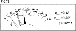
- Figure 7B gives an example of output of the external force "q", the restoring force losing lateral rollover limit external force “q max ", and the lateral rollover limit external force on the geometrical structure, "q ⁇ max ", which were obtained as a result of using a personal computer, which functions as the data processing apparatus 20, to process the external force measured in the middle of the vehicle 1 being subjected to a lateral G while traveling on a curved path, and the lateral rollover limit height "L max " and the center-of-gravity height "L”, which were obtained in advance by completing the 3-D center-of-gravity detection at the time of straight-line traveling.
- the first and second embodiments provide a lateral rollover risk warning device that is installed in a vehicle 1 that is supported by spring structures (tires 3 and suspensions 4) on both sides in the right-left direction across a vehicle axis 6 of a vehicle body, respectively, reporting the risk of the vehicle 1 being rolled over
- the lateral rollover risk warning device including a first acceleration sensor 11, which is a vertical direction physical amount detection means for detecting an external force applied in the vertical direction of the vehicle body; an angular velocity sensor 12, which is a rotational direction physical amount detection means for detecting a rotation around the vehicle axis 6 of the vehicle body; a limit index calculating means (an arithmetic part 21) that uses the results of detection by the first acceleration sensor 11 and the angular velocity sensor 12 to calculate an index of the limit at which the vehicle 1 is led to be rolled over; a second acceleration sensor 13, which is a right-left direction physical amount detection means for detecting an external force applied in the right-left direction of the vehicle body; a real-time
- the risk of the vehicle 1 rolling over laterally can be reported in real time during traveling on the basis of the results of detection by the first acceleration sensor 11, the angular velocity sensor 12, and the second acceleration sensor 13 installed on the vehicle body with no need for inputting the radius of a curved path in advance, and thus the vehicle 1 can be prevented from rolling over.
- the limit index calculating means (the arithmetic part 21) is configured to calculate a restoring force losing lateral rollover limit external force "q max ", which indicates the angle of the vehicle body 1, " ⁇ ", at a time when an external force exceeding the restoring force of the spring structures (the tires 3 and the suspensions 4) acts in the right-left direction, and thus the vehicle 1 is led to a rollover in the right-left direction, as a limit index.
- the driver can drive the vehicle 1, being careful not to allow the continuously varying rolling inclination angle " ⁇ " to reach the restoring force losing lateral rollover limit angle " ⁇ max ", and thus can prevent the vehicle 1 from rolling over.
- the limit index calculating means (the arithmetic part 21) is configured to calculate a restoring force losing lateral rollover limit angle "q max ", which indicates the external force "q" that exceeds the restoring force of the spring structures (the tires 3 and the suspensions 4), being applied in the right-left direction of the vehicle body, as a limit index.
- the driver can drive the vehicle 1, being careful not to allow the continuously varying external force "q" to reach the restoring force losing lateral rollover limit external force "q max ", and thus can prevent the vehicle 1 from rolling over.
- the limit index calculating means (the arithmetic part 21) is configured to calculate a lateral rollover limit external force on the geometrical structure, "q ⁇ max ", which indicates the external force that leads the vehicle 1 to a rollover on the geometrical structure, being applied in the right-left direction, even if the restoring force by the spring structures (the tires 3 and the suspensions 4) is sufficient, as a limit index.
- the driver can drive the vehicle 1, being careful not to allow the continuously varying rolling inclination angle " ⁇ " to reach the lateral rollover limit external force on the geometrical structure, "q ⁇ max ", while determining the level of the risk of rolling over on the geometrical structure in real time, and thus can prevent the vehicle 1 from rolling over.
- the lateral rollover limit external force on the geometrical structure, "q ⁇ max " can be determined from [Math 14]
- " ⁇ min " can be determined from [Math 13]. This can also be used as a lateral rollover limit index.
- the rolling inclination angle " ⁇ ” is obtained from [Math 09], and then if it is substituted into [Math 11], the angle " ⁇ " that is formed by a perpendicular drawn from the center of gravity, W, and the pertinent rolling-over radius "r” can be derived.
- the driver can identify the lateral rollover limit and the lateral rollover risk that depend upon the loading condition of the load.
- the arithmetic part 21a of the data processing apparatus 20a calculates a combination of the traveling speed "V" and the horizontal direction deflection angle " ⁇ " (the steering angle) with which the vehicle 1 is led to a rollover, as a limit condition, and, from the reporting part 24, outputs the pertinent limit condition and the piece of traveling information that has been received, as a piece of lateral rollover risk warning information.
- Figure 11A gives an example of output in the case where the traveling speed "V” has been received from the vehicle 1 as a piece of traveling information.
- a horizontal line X which indicates the traveling speed "V” that has been received, is displayed on the graph, and by the intersection point between the horizontal line X and [Math 17], the driver is notified of the limit horizontal direction deflection angle, " ⁇ max ", at which the vehicle 1 is led to a rollover.
- Figure 11B gives an example of output in the case where the horizontal direction deflection angle " ⁇ " has been received from the vehicle 1 as a piece of traveling information.
- a vertical line Y which indicates the horizontal direction deflection angle " ⁇ " that has been received, is displayed on the graph, and by the intersection point between the vertical line Y and [Math 17], the driver is notified of the limit traveling speed "V max ", at which the vehicle 1 is led to a rollover.
- the driver can compare the current traveling speed "V” with the limit traveling speed "V max ", and further can compare the current horizontal direction deflection angle " ⁇ " with the limit horizontal direction deflection angle, " ⁇ max ", whereby the driver can reliably determine the lateral rollover risk.
- the driver can grasp that, if the acceleration pedal is stepped down to raise the traveling speed "V", or the steering wheel is turned more to increase the horizontal direction deflection angle " ⁇ ", the vehicle 1 can be led to a lateral rollover, whereby the driver can prevent the vehicle 1 from being rolled over.
- the limit condition and the piece of traveling information are outputted from the reporting part 24 as a piece of lateral rollover risk warning information
- a result of comparison between the limit condition and the piece of traveling information may be outputted from the reporting part 24 as a piece of lateral rollover risk warning information, or a warning telling that the piece of traveling information has too closely approached the limit condition may be outputted from the reporting part 24 as a piece of lateral rollover risk warning information.
- a floating structure such as the vessel 7, that floats on the water surface has a maximum restoring force when it is located at the center of oscillation in the right-left direction, and as the floating structure is displaced in the lateral direction, the restoring force is gradually lost, resulting in all the restoring force being lost when the angle of horizontal oscillation inclination of ⁇ max being reached.
- the energy that horizontally moves the hull from the center of the oscillation in the right-left direction until it is at an angle of horizontal oscillation inclination of ⁇ max is equal to the potential energy that is required to bring up the center of gravity of the vessel 7 from a level corresponding to the oscillation radius "L" to that corresponding to the capsize limit oscillation radius "L max ".
- the rotational motion energy for changing the position of the vessel 7 for the oscillation radius L through the angle " ⁇ " is represented by the following expression, which can be obtained by integrating, by angle, the restoring moment towards the horizontal direction that is received from, for example, the floating force.
- V' denotes the natural frequency (the rolling frequency) of oscillation in the right-left direction of the center of gravity. 1 6 ⁇ V ′ m g L ⁇ tan ⁇
- the risk of capsize at the time of the vessel 7 being exposed to a lateral wind or a lateral wave, or the vessel 7 being steered into a turning-round motion can be estimated in real time.
- the same estimation as mentioned above may be performed.
- the capsize risk is discussed, however, the method allows calculation of a hull inclination angle that is estimated from a wave height when the wavelength becomes equal to "2b". Contrarily to this, the present invention as given in the fourth embodiment allows real-time determination of the risk of capsize at the time of exposure to a lateral wind, the risk of capsize at the time of turning-round by steering, and the risk of capsize of exposure to a lateral wave with a wavelength or wave height when the wavelength is not equal to "2b".
- the piece of lateral rollover warning information can be used as a piece of information notifying the driver of a risk of slip.
- the gripping force of the tires causes a lateral rollover, and, on a frozen path, there would occur a slip at the moment when the lateral rollover conditions in the present invention has been met. Therefore, the driver can identify the change in the external force "q" in real time, and can drive the vehicle, being careful not to allow the continuously varying external force "q" to too closely approach the restoring force losing lateral rollover limit external force "q max ", and thus can prevent the vehicle from slipping.
- the present invention is not limited to the above-mentioned embodiments, and within the technical scope of the present invention, the above-mentioned embodiments may be altered as appropriate.
- the number, location, geometry, and the like, of the above-mentioned component members are not limited to those as given in the above-mentioned embodiments, and may be altered into a number, location, geometry, and the like, that are suited for implementing the present invention. In each figure, the same component is provided with the same reference sign.
- the symbol 1 denotes a vehicle; 2 a cargo bed; 3 tires; 4 suspensions; 5 a driver's seat; 6 a vehicle axis; 7 a vessel; 10 an external force detector; 11 a first acceleration sensor; 12 an angular velocity sensor; 13 a second acceleration sensor; 14 an A/D converter; 20, 20a a data processing apparatus; 21, 21a an arithmetic part; 22 a storage part; 23 an operation part; 24 a reporting part; 25, 25a a receiving part; 26 a bus; and 30 a road surface.
Landscapes
- Engineering & Computer Science (AREA)
- Mechanical Engineering (AREA)
- Physics & Mathematics (AREA)
- Automation & Control Theory (AREA)
- Combustion & Propulsion (AREA)
- Ocean & Marine Engineering (AREA)
- Aviation & Aerospace Engineering (AREA)
- Chemical & Material Sciences (AREA)
- General Physics & Mathematics (AREA)
- Mathematical Physics (AREA)
- Transportation (AREA)
- Control Of Driving Devices And Active Controlling Of Vehicle (AREA)
- Testing Of Balance (AREA)
- Vehicle Body Suspensions (AREA)
Description
- The present invention relates to a lateral rollover risk warning device that reports the risk that a vehicle may be rolled over laterally.
- With the
Patent Document 1, the present inventor has proposed a technique that uses the 3-D center-of-gravity detection theory to calculate a limit center-of-gravity height beyond which a structure will be rolled over laterally, as the lateral rollover limit height, thereby determining the lateral rollover risk of a structure for which the weight or the weight distribution has not been clarified in advance, on the basis of the lateral rollover limit height that has been calculated. - Patent Document 1:
WO2008062867 - The biggest problem that has been presented in putting the technology of the
Patent Document 1 into service that utilizes the 3-D center-of-gravity detection theory for preventing a lateral rollover of a vehicle, such as various types of trains, various types of trucks, various types of buses, and various types of passenger vehicles, which are mobile bodies, is that the radius of a curved path of a road or a railway must be known in advance. For utilizing not only the lateral rollover limit speed expression in thePatent Document 1, but also any conventional lateral rollover limit speed expression, it is indispensable to input the radius of the curved path in advance. Particularly, in case of a general automobile traveling, it is difficult for the driver to know the radius of a curved path on which he or she is traveling, and in addition, since his or her handling of the wheel at the time of right or left turn at an intersection or at the time of a lane change is at his or her discretion, what curved path traveling would be made and the radius of the curved path that would be followed are far beyond the prediction ability of any technology. - In view of the above problem, the present invention has been made in order to solve the problem of the prior art, and it is an object of the present invention to provide a lateral rollover risk warning device that can report the risk of a vehicle rolling over laterally in real time during traveling with no need for inputting the radius of a curved path in advance.
- The lateral rollover risk warning device of the present invention is a lateral rollover risk warning device that is installed in a vehicle that is supported by spring structures on both sides in the right-left direction across a vehicle axis of a vehicle body, respectively, reporting the risk of the vehicle being rolled over, the lateral rollover risk warning device including: a vertical direction physical amount detection means for detecting an external force applied in the vertical direction of the vehicle body; a rotational direction physical amount detection means for detecting a rotation around the vehicle axis of the vehicle body; a limit index calculating means that uses the results of detection by the vertical direction physical amount detection means and the rotational direction physical amount detection means to calculate an index of the limit at which the vehicle is led to be rolled over; a right-left direction physical amount detection means for detecting an external force applied in the right-left direction of the vehicle body; a real-time index calculating means that uses the result of detection by the right-left direction physical amount detection means to calculate a comparative index to be compared with the limit index in real time; and a reporting means that uses the limit index and the comparative index to report a piece of lateral rollover risk warning information telling the risk of rolling over.
- Further, in the lateral rollover risk warning device of the present invention, the limit index calculating means may calculate a restoring force losing lateral rollover limit external force, which indicates an external force that exceeds the restoring force of the spring structures, being applied to the vehicle, as the limit index.
- Further, in the lateral rollover risk warning device of the present invention, the limit index calculating means may calculate a restoring force losing lateral rollover limit angle, which indicates the angle of the vehicle body at a time when an external force exceeding the restoring force of the spring structures acts in the right-left direction, and thus the vehicle is led to a rollover in the right-left direction, as the limit index.
- Further, in the lateral rollover risk warning device of the present invention, the limit index calculating means may calculate a lateral rollover limit external force on the geometrical structure, which indicates the external force that leads the vehicle to a rollover on the geometrical structure, being applied in the right-left direction, even if the restoring force by the spring structures is sufficient, as the limit index.
- In addition, the lateral rollover risk warning device of the present invention is a lateral rollover risk warning device that is installed in a vehicle that is supported by spring structures on both sides in the right-left direction across a vehicle axis of a vehicle body, respectively, reporting the risk of the vehicle being rolled over, the lateral rollover risk warning device including: a vertical direction physical amount detection means for detecting an external force applied in the vertical direction of the vehicle body; a rotational direction physical amount detection means for detecting a rotation around the vehicle axis of the vehicle body; a limit condition calculating means that uses the results of detection by the vertical direction physical amount detection means and the rotational direction physical amount detection means to calculate a combination of the traveling speed and the horizontal direction deflection angle with which the vehicle is led to a rollover, as a limit condition; a traveling information receiving means that receives either or both of the traveling speed and the horizontal direction deflection angle from the vehicle in real time as a piece of traveling information; and a reporting means that uses the limit condition and the piece of traveling information to report a piece of lateral rollover risk warning information telling the risk of rolling over.
- In addition, the lateral rollover risk warning device of the present invention is a lateral rollover risk warning device that is installed in a vessel that is supported by a floating force on both sides in the right-left direction across the centerline, respectively, reporting the risk of the vessel being rolled over, the lateral rollover risk warning device including: a vertical direction physical amount detection means for detecting an external force applied in the vertical direction of the vessel; a rotational direction physical amount detection means for detecting a rotation around the centerline of the vessel; a limit index calculating means that uses the results of detection by the vertical direction physical amount detection means and the rotational direction physical amount detection means to calculate an index of the limit at which the vessel is led to be rolled over; a right-left direction physical amount detection means for detecting an external force applied in the right-left direction of the vessel; a real-time index calculating means that uses the result of detection by the right-left direction physical amount detection means to calculate a comparative index to be compared with the limit index in real time; and a reporting means that uses the limit index and the comparative index to report a piece of lateral rollover risk warning information telling the risk of rolling over.
- In accordance with the present invention, there is provided an advantage that it is capable of reporting the risk of a vehicle rolling over laterally in real time on the basis of the result of detection by a detection means installed on a vehicle with no need for inputting the radius of a curved path in advance.
-
-
Figure 1 is a side view illustrating a configuration of a vehicle on which a lateral rollover risk warning device according to a first embodiment of the present invention is installed; -
Figure 2 is a rear view illustrating a configuration of a vehicle on which a lateral rollover risk warning device according to the first embodiment of the present invention is installed; -
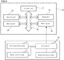
Figure 3 is a block diagram illustrating a configuration of a lateral rollover risk warning device according to the first embodiment of the present invention; -
Figure 4 is an explanatory drawing for explaining the limit of lateral rollover due to the loss of a restoring force; -
Figure 5 is a drawing illustrating an example of output of a piece of lateral rollover risk warning information on a lateral rollover risk warning device according to the first embodiment of the present invention; -
Figure 6 is an explanatory drawing for explaining the limit of lateral rollover on the geometrical structure; -
Figure 7 is a drawing illustrating an example of output of a piece of lateral rollover risk warning information on a lateral rollover risk warning device according to a second embodiment of the present invention; -
Figure 8 is a graph for explaining a method of calculating a lateral rollover limit external force on the geometrical structure with a lateral rollover risk warning device according to the second embodiment of the present invention; -
Figure 9 is a block diagram illustrating a configuration of a lateral rollover risk warning device according to a third embodiment of the present invention; -
Figure 10 is an explanatory drawing for explaining the turning-round motion of a vehicle at the time of traveling on a curved path; -
Figure 11 is a drawing illustrating an example of output of a piece of lateral rollover risk warning information on a lateral rollover risk warning device according to the third embodiment of the present invention; -
Figure 12 is a drawing illustrating an example of loading of an external force detector in a lateral rollover risk warning device according to a fourth embodiment of the present invention on a vessel; and -
Figure 13 is a drawing illustrating the relationship among the metacenter M, the center of gravity G, the center of buoyancy, the oscillation center axis O, and the GZ in the case where a vessel as a floating body structure that is loaded with a lateral rollover risk warning device according to the fourth embodiment of the present invention is brought to a greatly inclined state. - Next, embodiments of the present invention will be specifically explained with reference to the drawings.
- With reference to
Figure 1 , a lateral rollover risk warning device according to a first embodiment is loaded on avehicle 1, such as various types of trains, various types of trucks, various types of buses, and various types of passenger vehicles, which are mobile bodies, and includes anexternal force detector 10 that detects an external force applied to thevehicle 1, and adata processing apparatus 20 that, on the basis of the external force that has been detected by theexternal force detector 10, generates a piece of lateral rollover risk warning information telling the risk of lateral rollover. - With reference to
Figure 1 andFigure 2 , thevehicle 1 is a truck including acargo bed 2 on which a cargo is loaded, and is erected at a certain level from theroad surface 30, the mass (including the load of the cargo) of thevehicle 1 being supported by a cushioning elastic force comprised oftires 3 andsuspensions 4. Then, when thevehicle 1 is traveled, thetires 3 continue to tread on the irregularities of theroad surface 30, thereby a random external disturbance being transmitted to thecargo bed 2 of thevehicle 1 through thetires 3 and thesuspensions 4. As shown inFigure 1 andFigure 2 , the direction perpendicular to the placing surface of thecargo bed 2 is defined as an up-down direction; the direction along the longitudinal width of thevehicle 1 as a front-rear direction; and the direction along the crosswise width of thevehicle 1 as a right-left direction. In addition, the self-weight direction in which the gravity acts is defined as a Z-axis direction; the direction which is orthogonal to the Z-axis direction and the front-rear direction, respectively, as an X-axis direction; and the direction which is orthogonal to the Z-axis direction and the right-left direction, respectively, as a Y-axis direction. In the state in which thecargo bed 2 is level, the up-down direction coincides with the Z-axis direction; the front-rear direction with the Y-axis direction; and the right-left direction with the X-axis direction, respectively. - The right and left cushioning elastic forces each comprised of
tires 3 andsuspensions 4 are disposed in a linear symmetry with respect to avehicle axis 6 that is located at the center in the right-left direction of thecargo bed 2 and extends in the front-rear direction thereof. Therefore, thecargo bed 2 is supported by approximately the same elastic force on both sides across thevehicle axis 6, and when an external disturbance is transmitted to thecargo bed 2 of thevehicle 1 through thetires 3 andsuspensions 4, there is brought about a state in which a horizontal oscillation in the direction of rotation around thevehicle axis 6 as the oscillation central axis, and a vertical oscillation in the up-down direction can be made. - The
external force detector 10 is installed at the center in the right-left direction of thecargo bed 2, and thedata processing apparatus 20 is installed in a driver'sseat 5. The installation location of theexternal force detector 10 is not limited to thecargo bed 2, provided that theexternal force detector 10 is installed in the vehicle body of thevehicle 1 that is supported by the elastic forces. In addition, for a trailer truck that is configured such that a container chassis and a tractor can be disconnected, theexternal force detector 10 may be disposed in the tractor. Further, theexternal force detector 10 may be installed in a location that is away from the center to a certain degree, being displaced forward or backward, or rightward or leftward, within a range in which there occurs no problem of a wrong detection for motions affected by another axis. - With reference to
Figure 3 , theexternal force detector 10 includes afirst acceleration sensor 11, anangular velocity sensor 12, asecond acceleration sensor 13, and anA-D converter 14. With thefirst acceleration sensor 11, the sensitivity axis is adjusted such that the acceleration in the up-down (self-weight) direction (the Z-axis direction shown inFigure 1 andFigure 2 ), in other words, the vertical oscillation of thecargo bed 2 in the up-down direction is detected. With theangular velocity sensor 12, the sensitivity axis is adjusted such that the angular velocity in a direction of rotation around thevehicle axis 6. Hereinafter, the direction of rotation around thevehicle axis 6 is referred to as the rolling direction. With thesecond acceleration sensor 13, the sensitivity axis is adjusted such that the acceleration in the right and left direction (the X-axis direction shown inFigure 2 ), in other words, the external force in the right-left direction that is applied to thecargo bed 2 is detected. - In addition, the
first acceleration sensor 11, theangular velocity sensor 12, and thesecond acceleration sensor 13 are not particularly limited, and, for example, a crystal tuning fork type sensor or an oscillation type sensor may be used, and as thefirst acceleration sensor 11, theangular velocity sensor 12, and thesecond acceleration sensor 13, a three-axis (three dimensional) acceleration/angular velocity sensor may also be used. TheA-D converter 14 converts analog signals (detection results) outputted from thefirst acceleration sensor 11, theangular velocity sensor 12, and thesecond acceleration sensor 13 into digital signals to output them to thedata processing apparatus 20. Further, instead of thesecond acceleration sensor 13, an angular velocity sensor that detects a yaw angular velocity is installed horizontally, and with the detection result obtained, a trigonometric function may be used to determine the acceleration in the right-left direction. - The
data processing apparatus 20 is an information processing apparatus, such as a personal computer, and generates a piece of lateral rollover risk warning information on the basis of the result of detection that has been performed by theexternal force detector 10. - Referring to
Figure 3 , thedata processing apparatus 20, which is an information processing apparatus, includes anarithmetic part 21 comprised of a microprocessor, and the like; astorage part 22 comprised of an ROM (read-only memory), an RAM (random access memory), and the like; anoperation part 23, such as a keyboard; a reportingpart 24, such as a liquid crystal display or a speaker; and areception part 25, the respective parts being connected by abus 26. - In the
storage part 22, a calculation program for generating a piece of lateral rollover risk warning information, and various constants to be inputted that are required for the calculation in question are stored. Thearithmetic part 21 stores the outputs from theexternal force detector 10 in thestorage part 22 for a certain period of time; generates a piece of lateral rollover risk warning information in accordance with the calculation program stored in thestorage part 2; and outputs the piece of lateral rollover risk warning information from thereporting part 24. - Next, the method of generating a piece of lateral rollover risk warning information will be explained in detail.
- When the
vehicle 1 is traveled, the vehicle body of thevehicle 1 will make an oscillation (characteristic vibration) as shown inFigure 4A on the basis of a motion having a natural period (frequency) that is dependent on the cushioning elastic force comprised of thetires 3 and thesuspensions 4, the weight of the vehicle body (including the cargo, and the like) that is oscillated, being supported by the cushioning elastic force for the vehicle 1 (thetires 3 and the suspensions 4), and the location of the center of gravity, W. This motion is provided in the state in which the movement in the right-left direction (the X-axis direction) is restricted by thevehicle axis 6. Therefore, thefirst acceleration sensor 11 accurately detects the reciprocating motion of the center of gravity, W, of the vehicle body in the up-down direction as a vertical oscillation in the up-down direction, while theangular velocity sensor 12 detects the simple pendulum motion of the center of gravity, W, of the vehicle body around thevehicle axis 6 as a horizontal oscillation in the direction of rotation. - The result of detection by the first acceleration sensor 11 (the acceleration in the up-down direction) and the result of detection by the angular velocity sensor 12 (the angular velocity in the rolling direction) are inputted to the
data processing apparatus 20, and the detection results are stored in a certain period of time in thestorage part 22. Then, thearithmetic part 21 of thedata processing apparatus 20 determines the vertical oscillation frequency "v'" for the vertical oscillation in the up-down direction from the result of detection by the first acceleration sensor 11 (the acceleration in the up-down direction), which is stored in thestorage part 22, while determining the horizontal oscillation frequency "V'" for the horizontal oscillation in the rolling direction from the result of detection by the angular velocity sensor 12 (the angular velocity in the rolling direction), which is stored in thestorage part 22. In addition, from the result of detection by the angular velocity sensor 12 (the angular velocity in the rolling direction), thearithmetic part 21 determines the angle between the perpendicular center line passing through thevehicle axis 6 and the rolling center line giving the center of horizontal oscillation as an oscillation central angle "α". - The central angle "α" for the oscillation is an inclination angle "α" in a rolling direction of the vehicle body (the cargo bed 2) with respect to the horizontal plane in a standstill state (hereinafter to be referred to as an inclination angle "α" in a standstill state). Therefore, a sensor for measuring the angle of the vehicle body (the cargo bed 2) in a standstill state, such as an inclination angle sensor, may be mounted to the vehicle body (the cargo bed 2) for measuring the inclination angle "α" in a standstill state. In addition, although labor and time are required, it is possible to use a level, or the like, to make a visual measurement of the inclination angle "α" in a standstill state, and input the measurement from the
operation part 23 for setting. Further, a measuring means, such as a gyro, which can measure the angle of the vehicle body (the cargo bed 2) may be provided for measuring the inclination angle "α" in a standstill state, or determining the central angle "α" for the oscillation from the result of measurement. Further, the inclination angle "α" may be determined by the inclination angle calculation device that has been proposed by the present applicant withEP2508404A e.g.PCT/JP2010/007060 vehicle 1 is any one of the various types of trains, various types of buses, various types of passenger vehicles, and the like, and the inclination of the vehicle body in the loaded state can be expected to be small, the inclination angle "α" in a standstill state may be changed into a constant, being assumed to be equal to 0. - Next, the
arithmetic part 21 calculates, on the basis of the vertical oscillation frequency "v'" that has been determined, a lateral rollover limit height Lmax, which indicates the limit of center-of-gravity height beyond which thevehicle 1 comes to a lateral rollover in a right-left direction, while, on the basis of the vertical oscillation frequency "v'", the horizontal oscillation frequency "V'", and the central angle "α" that have been determined, calculating a center-of-gravity height in the up-down direction, "L", from thevehicle axis 6 to the center of gravity, W, of the vehicle body, on the assumption that the center of gravity, W, of the vehicle body is above thevehicle axis 6. The lateral rollover limit height Lmax is a height at which thevehicle 1 will be rolled over laterally, if the center of gravity of thevehicle 1 is located at a level higher than the lateral rollover limit height Lmax. In addition, the terms, such as lateral rollover, overturning, and turnover, are considered as synonyms which express the phenomenon that the stability of the center of gravity of a matter cannot be held, the rotational motion being progressed, resulting in the matter inevitably falling or collapsing in the gravitational direction. Hereinbelow, in the present embodiment and the other embodiments, the term "lateral rollover" will be used as a word that is representative of such synonyms. - The lateral rollover limit height Lmax and the center-of-gravity height "l" can be determined by using the following equations ([Math 01] and [Math 02]), which have been proposed by the present inventor with
WO2013084857A e.g.PCT/JP2012/081322 vehicle axis 6 as the oscillation central axis and the center of gravity, W, "L'", is expressed by the equation: L'2 = l2 + s2.

- In [Math 01], the symbol "π" denotes the circular constant; "g" the gravitational acceleration; and "b" the distance between the elastic forces (the
tires 3 and the suspensions 4) on the right and left sides across thevehicle axis 6. In [Math 02], the quadratic coefficient, the linear coefficient, and the constant terms can be defined using the vertical oscillation frequency "v'", the horizontal oscillation frequency "V'", and the central angle "α" that have been determined. Therefore, thearithmetic part 21 calculates a center-of-gravity height "l" by operating [Math 02] with the vertical oscillation frequency "v'", the horizontal oscillation frequency "V'", and the central angle "α". - As indicated in Japanese Patent Application
2013-220098 - Considering the state as depicted in
Figure 4B in which the center of gravity is not displaced rightward or leftward, i.e., the state in which s = 0, although the same restoring force as that in [Math 02] being provided (the values of "v'" and "V'" are the same as those in [Math 02]), and assuming that the center-of-gravity height at that time is "L", [Math 02] can be rewritten as the following equation [Math 03].
- Since the restoring force in [Math 03] is the same as that in [Math 02], the lateral rollover limit is also the same. Therefore, once the values of "v"' and "V"' have been obtained, use of [Math 03] will reduce the labor required to derive the lateral rollover limit, and lower the cost of the device. Specifically, the need for determining the inclination angle "α" in a standstill state is eliminated, whereby the variety of schemes as mentioned in the paragraph [0020] can be excluded.
- Next, on the basis of the lateral rollover limit height "Lmax" and the center-of-gravity height "L" that have been determined, the
arithmetic part 21 calculates an angle of limit in the rolling direction at which thevehicle 1 will lose the restoring force by the right and left elastic forces (thetires 3 and the suspensions 4), leading to a lateral rollover in the right or left direction (hereinafter to be referred to as a restoring force losing lateral rollover limit angle "θmax"), as a limit index. Hereinafter, the method of calculating the restoring force losing lateral rollover limit angle "θmax" will be explained. - In the state in which the
vehicle 1 is traveling straight while not rolling over, the location of the lateral rollover limit height "Lmax" is always above that of the center-of-gravity height "L". In other words, in order to cause the mobile body to be rolled over laterally, it is required to give potential energy equal to the energy for bringing up the location of the center-of-gravity height "L" to that of the lateral rollover limit height "Lmax". In addition, if thevehicle 1 is inclined (rotated) in a lateral direction (the rolling direction) with a force, it is finally rolled over, losing the restoring force, when a certain limit angle in the rolling direction (the restoring force losing lateral rollover limit angle "θmax") is reached. The restoring force is the elastic energy that supports thevehicle 1 from the right and left sides. Therefore, the relationship between the positional energy that causes thevehicle 1 to be rolled over and the elastic energy can be expressed by the following equation.
- In [Math 04], the symbol "m" denotes the weight of the vehicle body (including the cargo, and the like) that is oscillated, being supported by the cushioning elastic forces (the
tires 3 and the suspensions 4), and the symbol "k" denotes the respective spring constants for the right and left elastic forces (thetires 3 and the suspensions 4). - Here, since k/m can be expressed as k/m = 2π2v'2, [Math 04] can be deformed into the following equation.

- Further, using [Math 01] to deform [Math 05] will give the following equation.

- [Math 06] indicates that the restoring force losing lateral rollover limit angle "θmax" can be calculated with the use of the lateral rollover limit height "Lmax" and the center-of-gravity height "L". The lateral rollover limit height "Lmax", the center-of-gravity height "L", and the restoring force losing lateral rollover limit angle "θmax" are theoretically invariable so long as the situation of the vehicle body is not changed. Therefore, detection by the
first acceleration sensor 11 and theangular velocity sensor 12; calculation of the vertical oscillation frequency "v'" and the horizontal oscillation frequency "V'"; calculation of the lateral rollover limit height "Lmax" and the center-of-gravity height "L"; and calculation of the restoring force losing lateral rollover limit angle "θmax" need not be performed in real time, and can be conducted at the start of traveling thevehicle 1 or at predetermined time intervals. - Next, on the basis of the result of detection by the second acceleration sensor 13 (the acceleration in the right-left direction), the
arithmetic part 21 calculates an inclination angle of thevehicle 1 in the rolling direction (hereinafter to be referred to as the rolling inclination angle "θ") as a comparative index that is to be compared with the restoring force losing lateral rollover limit angle "θmax" as a limit index, and outputs it from the reportingpart 24 as a piece of lateral rollover warning information together with the restoring force losing lateral rollover limit "θmax" that has been determined. Hereinafter, the method of calculating the rolling inclination angle "θ". - If an external force is applied to the
vehicle 1 from a lateral direction, thevehicle 1 is caused to be inclined (turned in the rolling direction), the rolling moment and the restoring force by the right and left springs are faced against each other. Therefore, as shown inFigure 4B , if the external force is formulated on the assumption that the force applied to the center of gravity, W, of thevehicle 1 in the tangential direction is "f", and the rolling inclination angle of thevehicle 1 is "θ", the following equation can be obtained.
- Here, in order to make the development of the later-mentioned equation smooth, if the component "f" of the external force in the tangential direction is expressed by using a value of "q" of the ratio of the external force to the gravity "g", an equation of f = mqg × cos θ is obtained, and from [Math 07], the external force "q" (the value of the ratio to the gravity) can be expressed by the following equation.

- Here, if k/m is expressed as k/m = 2π2v'2, and [Math 08] is deformed by using [Math 09], the following equation can be obtained.

- [Math 09] indicates that, once the lateral rollover limit height "Lmax" and the center-of-gravity height "L" have been determined, based on the 3-D center-of-gravity detection theory, thereafter, simply by measuring the lateral G (the lateral acceleration), the rolling inclination angle "θ" of the
vehicle 1 as a mobile body during traveling can be determined in real time. Thearithmetic part 21 uses the result of detection by thesecond acceleration sensor 13 that is performed in real time (the acceleration in the right-left direction), the lateral rollover limit height "Lmax", and the center-of-gravity height "L" to operate [Math 09], thereby calculating the rolling inclination angle "θ" of thevehicle 1 in real time. - Next, the
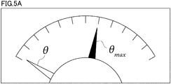
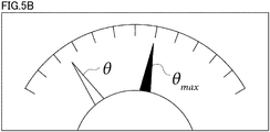
arithmetic part 21 causes the reportingpart 24 to output the restoring force losing lateral rollover limit angle "θmax", which has been calculated as a limit index by using [Math 06], and the rolling inclination angle "θ" of thevehicle 1, which has been calculated as a comparative index using [Math 09], as a piece of lateral rollover risk warning information for notifying the driver thereof.Figure 5A andFigure 5B show examples of output as meter readings of the restoring force losing lateral rollover limit angle "θmax" and the rolling inclination angle "θ". The result of detection by the second acceleration sensor 13 (the acceleration in the right-left direction) is varied depending upon the steering angle and the vehicle speed, and the rolling inclination angle "θ" is continuously varied in correspondence to the result of detection by the second acceleration sensor 13 (the acceleration in the right-left direction). Then, once the arrow of the rolling inclination angle "θ" has reached that of the restoring force losing lateral rollover limit angle "θmax", an external force that exceeds the restoring force of the spring structures (thetires 3 and the suspensions 4) that support thevehicle 1 acts in the right-left direction, resulting in thevehicle 1 being rolled over in the right-left direction. -
Figure 5A shows the state at the time of traveling substantially straight, the arrow of the rolling inclination angle "θ" indicating approximately zero. On the other hand,Figure 5B shows the state in which thevehicle 1 is subjected to a lateral G at the time of traveling on a curved path, the arrow of the rolling inclination angle "θ" approaching that of the restoring force losing lateral rollover limit angle "θmax". In either of the examples shown inFigure 5A andFigure 5B , the arrow of the rolling inclination angle "θ" is sufficiently away from that of the restoring force losing lateral rollover limit angle "θmax", whereby it can be confirmed in real time during traveling that there is no lateral rollover risk. Thereby, the driver can drive thevehicle 1, being careful not to allow the continuously varying rolling inclination angle "θ" to reach the restoring force losing lateral rollover limit angle "θmax", and thus can prevent thevehicle 1 from rolling over. - In [Math 09], if it is assumed that the rolling inclination angle "θ" is equal to the restoring force losing lateral rollover limit angle "θmax", and [Math 06] is substituted into [Math 09], the limit external force with which the restoring force by the right and left elastic forces (the
tires 3 and the suspensions 4) is lost, thevehicle 1 being led to a lateral rollover in the right-left direction (hereinafter to be referred to as the restoring force losing lateral rollover limit external force "qmax") can be determined as a limit index by using the following equation.
- Therefore, the
arithmetic part 21 may determine the "q", which is a value of the ratio of the external force to the gravity "g", as a comparative index from the result of detection by the second acceleration sensor 13 (the acceleration in the right-left direction), and cause the reportingpart 24 to output the restoring force losing lateral rollover limit external force "qmax" as a limit index, which has been determined by means of [Math 10], and the external force "q" as a comparative index as a piece of lateral rollover risk warning information for notifying the driver thereof. Also in this case, the driver can identify the change in the external force "q" in real time, and can drive thevehicle 1, being careful not to allow the continuously varying external force "q" to reach the restoring force losing lateral rollover limit external force "qmax", and thus can prevent thevehicle 1 from rolling over. - The negative sign in [Math 09] and [Math 10] means that the direction of the restoring force by the springs always acts in a direction opposite to the direction of an external force. Therefore, in the case where the magnitude of the external force itself is required, the absolute value of the pertinent value in [Math 09] and [Math 10] can be used. Accordingly, in
Figure 5A andFigure 5B , the angle is indicated as the absolute value on the basis of this concept. - In addition, in the first embodiment, there has been provided a configuration in which the limit index and the comparative index are outputted from the reporting
part 24 as a piece of lateral rollover risk warning information, however, a result of comparison between the limit index and the comparative index may be outputted from the reportingpart 24 as a piece of lateral rollover risk warning information, or a warning telling that the comparative index has too closely approached the limit index may be outputted from the reportingpart 24 as a piece of lateral rollover risk warning information. - The first embodiment is based on a lateral rollover phenomenon that occurs when an external force "f" exceeding the restoring force of the spring structures (the
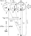
tires 3 and the suspensions 4) supporting thevehicle 1 is exerted. In a lateral rollover risk warning device according to a second embodiment, a piece of lateral rollover risk warning information is generated based on another lateral rollover phenomenon. In other words, even if the restoring force by the spring structures (thetires 3 and the suspensions 4) is sufficient, the center of gravity, W, is rolled over with a straight line connecting between the location of the center of gravity, W, and the edge of thevehicle 1 on the rolling-over side (the point of contact with the road surface) being given as a rolling-over radius "r", as shown inFigure 6 . Such lateral rollover phenomenon is referred to as a lateral rollover on the geometrical structure. Here, an angle "ϕ" that is formed by a perpendicular drawn from the center of gravity, W, and the pertinent rolling-over radius "r" can be expressed by the following equation. The symbol "h" denotes the height from theroad surface 30 to thevehicle axis 6.
- At this time, when the moment with which the external force acts to roll over the center of gravity, W, in the tangential direction of a locus of the center of gravity, W, exceeds the moment with which the gravity "mg" always holds down the center of gravity, W, in a direction opposite to the direction of lateral rollover, there occurs a lateral rollover on the geometrical structure. Therefore, the condition of a lateral rollover limit on the geometrical structure can be expressed by the following equation. Hereinafter, the external force of limit on the geometrical structure with which the
vehicle 1 is led to a lateral rollover in the right-left direction is referred to as the lateral rollover limit external force on the geometrical structure, "qϕmax".
- Accordingly, by finding the value of "q" that holds [Math 12], the lateral rollover limit external force on the geometrical structure, "qϕmax", for the
vehicle 1 can be expressed by the following equation. The symbol "ϕmin" denotes a minimum value of "ϕ" that provides the lateral rollover limit external force on the geometrical structure, "qφmax".
- As can be seen from
Figure 6 , the values of "ϕmin" and "qϕmax" are a function of "θ". In other words, the angle "ϕ" is at maximum when the center of gravity is at the center in the right-left direction, while it is at minimum when thevehicle 1 reaches the lateral rollover limit on the geometrical structure. Contrarily to this, the angle "θ" is at maximum when thevehicle 1 reaches the lateral rollover limit on the geometrical structure. Then, by substituting [Math 11] into [Math 13], and further [Math 09] thereinto, the lateral rollover limit external force on the geometrical structure, "qϕmax", for thevehicle 1 can be expressed by the following equation.
- The value of "q" that holds [Math 14] is the value of "qϕmax". It is difficult to analytically solve [Math 14], however, if a well-known technique for solving an equation by numerical value analysis is applied, the value of "qϕmax" can be obtained. In other words, with the
arithmetic part 21, the lateral rollover limit height "Lmax" and the center-of-gravity height "L" are substituted into [Math 14] to solve it for calculating a lateral rollover limit external force on the geometrical structure, "qϕmax", for thevehicle 1 as a limit index. In the second embodiment, thearithmetic part 21 determines the "q", which is a value of the ratio of the external force to the gravity "g", as a comparative index from the result of detection by thesecond acceleration sensor 13, and causes the reportingpart 24 to output the lateral rollover limit external force on the geometrical structure, "qϕmax", as a limit index, and the "q" as a comparative index as a piece of lateral rollover risk warning information for notifying the driver thereof. Thereby, the driver can identify the change in the external force "q" in real time, and can drive thevehicle 1, being careful not to allow the continuously varying external force "q" to reach the lateral rollover limit external force on the geometrical structure, "qϕmax", for thevehicle 1, while determining the level of risk of rolling over on the geometrical structure in real time, and thus can prevent thevehicle 1 from rolling over. - In addition, in the second embodiment, there has been provided a configuration in which the limit index and the comparative index are outputted from the reporting
part 24 as a piece of lateral rollover risk warning information, however, a result of comparison between the limit index and the comparative index may be outputted from the reportingpart 24 as a piece of lateral rollover risk warning information, or a warning telling that the comparative index has too closely approached the limit index may be outputted from the reportingpart 24 as a piece of lateral rollover risk warning information. - In order to verify the advantages of the first and second embodiments, a demonstration experiment was conducted using a large-sized sightseeing bus as the
vehicle 1. By installing theexternal force detector 10 on a vehicle floor, and using a personal computer that functions as thedata processing apparatus 20, the external force "q"; the restoring force losing lateral rollover limit external force "qmax", which has been mentioned in the first embodiment; and the lateral rollover limit external force on the geometrical structure, "qϕmax", which has been mentioned in the second embodiment, were generated as pieces of lateral rollover risk warning information to be displayed. -
Figure 7A gives an example of output of the external force "q", the restoring force losing lateral rollover limit external force "qmax", and the lateral rollover limit external force on the geometrical structure, "qϕmax", which were obtained as a result of completing the 3-D center-of-gravity detection (calculating the lateral rollover limit height "Lmax" and the center-of-gravity height "L") at the time of straight-path traveling shortly after the start of the demonstration experiment, and using a personal computer, which functions as thedata processing apparatus 20, to process them.Figure 7B gives an example of output of the external force "q", the restoring force losing lateral rollover limit external force "qmax", and the lateral rollover limit external force on the geometrical structure, "qϕmax", which were obtained as a result of using a personal computer, which functions as thedata processing apparatus 20, to process the external force measured in the middle of thevehicle 1 being subjected to a lateral G while traveling on a curved path, and the lateral rollover limit height "Lmax" and the center-of-gravity height "L", which were obtained in advance by completing the 3-D center-of-gravity detection at the time of straight-line traveling. - In
Figure 7A , because thevehicle 1 was traveling on a straight path, the arrow that indicates the external force "q" points to approx. zero. In addition, the arrow indicating the external force "q" is located sufficiently away from the arrow for the restoring force losing lateral rollover limit external force "qmax", and that for the lateral rollover limit external force on the geometrical structure, "qϕmax", whereby it can be identified in real time during traveling that thevehicle 1 is free from lateral rollover risk. - In
Figure 7B , because thevehicle 1 was being subjected to a lateral G, traveling on a curved path, the arrow that indicates the external force "q" is distinctly deflected towards right, telling a rise in the external force "q". Also in this case, the arrow indicating the external force "q" is yet located sufficiently away from the arrow for the restoring force losing lateral rollover limit external force "qmax", and that for the lateral rollover limit external force on the geometrical structure, "qϕmax", whereby it can be identified in real time during traveling that thevehicle 1 is free from lateral rollover risk. In this way, since the driver of thevehicle 1 can acquire a piece of lateral rollover risk warning information of the present invention in real time, he or she can make an appropriate safe drive even in, for example, transportation of a cargo that is unknown about the loading condition. - If
Figure 7A andFigure 7B are compared with each other, it can be known that the arrow of the restoring force losing lateral rollover limit external force "qmax" is substantially unchanged in its position. This is attributable to the fact that the restoring force losing lateral rollover limit external force "qmax" is a lateral rollover limit that is based on the restoring energy as can be seen from [Math 10]. If, with thevehicle 1, the vehicle body has no abnormality, and the loading weight is unchanged, the restoring force is constant during traveling. Therefore, calculation of the restoring force losing lateral rollover limit external force "qmax" need not be performed in real time, and can be conducted at the start of traveling thevehicle 1 or at predetermined time intervals. - The graph given in
Figure 8 is a graph that has been prepared on the basis of the results of the demonstration experiment, indicating that [Math 14] has a solution. InFigure 8 , the abscissa represents the value of "q", while the ordinate gives the result of substituting the value of "q" into both sides of [Math 14], and then subtracting the left side from the right side of [Math 14] . The value on the abscissa at a location where the curve inFigure 8 intersects with the abscissa (the value on the ordinate is equal to 0), i.e., approximately 0.255 is the value of the lateral rollover limit external force on the geometrical structure, "qϕmax". - As described above, the first and second embodiments provide a lateral rollover risk warning device that is installed in a vehicle 1 that is supported by spring structures (tires 3 and suspensions 4) on both sides in the right-left direction across a vehicle axis 6 of a vehicle body, respectively, reporting the risk of the vehicle 1 being rolled over, the lateral rollover risk warning device including a first acceleration sensor 11, which is a vertical direction physical amount detection means for detecting an external force applied in the vertical direction of the vehicle body; an angular velocity sensor 12, which is a rotational direction physical amount detection means for detecting a rotation around the vehicle axis 6 of the vehicle body; a limit index calculating means (an arithmetic part 21) that uses the results of detection by the first acceleration sensor 11 and the angular velocity sensor 12 to calculate an index of the limit at which the vehicle 1 is led to be rolled over; a second acceleration sensor 13, which is a right-left direction physical amount detection means for detecting an external force applied in the right-left direction of the vehicle body; a real-time index calculating means (the arithmetic part 21) that uses the result of detection by the second acceleration sensor 13 to calculate a comparative index to be compared with the limit index in real time; and a reporting part 24 that uses the limit index and the comparative index to report a piece of lateral rollover risk warning information telling the risk of rolling over.
- With this configuration, the risk of the
vehicle 1 rolling over laterally can be reported in real time during traveling on the basis of the results of detection by thefirst acceleration sensor 11, theangular velocity sensor 12, and thesecond acceleration sensor 13 installed on the vehicle body with no need for inputting the radius of a curved path in advance, and thus thevehicle 1 can be prevented from rolling over. - In addition, in the first embodiment, the limit index calculating means (the arithmetic part 21) is configured to calculate a restoring force losing lateral rollover limit external force "qmax", which indicates the angle of the
vehicle body 1, "θ", at a time when an external force exceeding the restoring force of the spring structures (thetires 3 and the suspensions 4) acts in the right-left direction, and thus thevehicle 1 is led to a rollover in the right-left direction, as a limit index. - With this configuration, the driver can drive the
vehicle 1, being careful not to allow the continuously varying rolling inclination angle "θ" to reach the restoring force losing lateral rollover limit angle "θmax", and thus can prevent thevehicle 1 from rolling over. - In addition, in the first embodiment, the limit index calculating means (the arithmetic part 21) is configured to calculate a restoring force losing lateral rollover limit angle "qmax", which indicates the external force "q" that exceeds the restoring force of the spring structures (the
tires 3 and the suspensions 4), being applied in the right-left direction of the vehicle body, as a limit index. - With this configuration, the driver can drive the
vehicle 1, being careful not to allow the continuously varying external force "q" to reach the restoring force losing lateral rollover limit external force "qmax", and thus can prevent thevehicle 1 from rolling over. - In addition, in the second embodiment, the limit index calculating means (the arithmetic part 21) is configured to calculate a lateral rollover limit external force on the geometrical structure, "qϕmax", which indicates the external force that leads the
vehicle 1 to a rollover on the geometrical structure, being applied in the right-left direction, even if the restoring force by the spring structures (thetires 3 and the suspensions 4) is sufficient, as a limit index. - With this configuration, the driver can drive the
vehicle 1, being careful not to allow the continuously varying rolling inclination angle "θ" to reach the lateral rollover limit external force on the geometrical structure, "qϕmax", while determining the level of the risk of rolling over on the geometrical structure in real time, and thus can prevent thevehicle 1 from rolling over. Further, if the lateral rollover limit external force on the geometrical structure, "qϕmax", can be determined from [Math 14], "φmin" can be determined from [Math 13]. This can also be used as a lateral rollover limit index. If the external force "q" is obtained from thesecond acceleration sensor 13, the rolling inclination angle "θ" is obtained from [Math 09], and then if it is substituted into [Math 11], the angle "φ" that is formed by a perpendicular drawn from the center of gravity, W, and the pertinent rolling-over radius "r" can be derived. By observing the "φ" with respect to the "φmin" in real time, the driver can identify the lateral rollover limit and the lateral rollover risk that depend upon the loading condition of the load. - In the first and second embodiments, the rolling inclination angle "θ" for the
vehicle 1 and the external force "q" are calculated in real time on the basis of the result of detection by the second acceleration sensor 13 (the acceleration in the right-left direction), thereby the driver being caused to recognize the lateral rollover risk. Contrarily to this, in the third embodiment, as shown inFigure 9 , the receivingpart 25a of thedata processing apparatus 20a receives either or both of the traveling speed "V" and the horizontal direction deflection angle "β" (the steering angle) from thevehicle 1 in real time as a piece of traveling information. Then, thearithmetic part 21a of thedata processing apparatus 20a calculates a combination of the traveling speed "V" and the horizontal direction deflection angle "β" (the steering angle) with which thevehicle 1 is led to a rollover, as a limit condition, and, from the reportingpart 24, outputs the pertinent limit condition and the piece of traveling information that has been received, as a piece of lateral rollover risk warning information. - Here, the method of calculating a limit condition will be explained.
- As shown in
Figure 1 , it is assumed that thevehicle 1 is making a turning-round motion at a definite angle in the horizontal direction during cornering at the time of traveling on a curved path. If thevehicle 1 is a train or automobile, the horizontal direction deflection angle "β" is equal to the steering angle (for an automobile, the angle at which thetires 3 are directed with respect to the direction of straight-line advance), so long as thevehicle 1 makes no side skip. Here, assuming that the centrifugal force acting on thevehicle 1 in the horizontal direction (the lateral direction) is "fβ", the wheel space between the front and rear axles of thevehicle 1 is "H", and the radius of a traveling circle for thevehicle 1 is "R", then, fromFigure 4 and the formula of uniform circular motion, the relationship between the traveling speed "V" and the external force "q" can be expressed by the following equation.
- Here, from
Figure 10 , since R = H/2 × sin β, the relationship among the horizontal direction deflection angle "β", the traveling speed "V", and the external force "q" can be expressed by the following equation.
- Since the gravity acceleration "g" and the wheel space "H" are constants, by substituting the restoring force losing lateral rollover limit external force "qmax" into [Math 16], the relationship between the horizontal direction deflection angle "β" and the traveling speed "V" that lead the
vehicle 1 to a rollover can be expressed by the following equation.
- In other words, [Math 17] is a relational expression of lateral rollover limit between the traveling speed "V" and the horizontal direction deflection angle "β", being a limit condition indicating a combination of the traveling speed "V" and the horizontal direction deflection angle "β" (the steering angle) with which the
vehicle 1 is led to a lateral rollover. In [Math 17], if the traveling speed "V" is defined, the limit horizontal direction deflection angle, "βmax", at which thevehicle 1 is led to a rollover, is determined, and, if the horizontal direction deflection angle "β" is defined, the limit traveling speed "Vmax", at which thevehicle 1 is led to a rollover, is determined. - As shown in
Figure 11A ,Figure 11B , andFigure 11C , thearithmetic part 21a generates a graph in which [Math 17], which is the limit condition, and the piece of traveling information that has been received from thevehicle 1 are plotted, as a piece of lateral rollover risk warning information, and outputs it from the reportingpart 24. InFigure 11A ,Figure 11B , andFigure 11C , the abscissa represents the horizontal direction deflection angle "β", while the ordinate the traveling speed "V". As can be seen fromFigure 11A ,Figure 11B , andFigure 11C , with [Math 17], as the traveling speed "V" is raised, the range of the horizontal direction deflection angle "β" (the range in which safe steering is possible) is rapidly narrowed down. Further, it can be seen that, when the traveling speed "V" is increased, a slight amount of steering can immediately lead to a lateral rollover of thevehicle 1. Such understanding agrees with a testimony of a driver who caused a lateral rollover accident. -
Figure 11A gives an example of output in the case where the traveling speed "V" has been received from thevehicle 1 as a piece of traveling information. A horizontal line X, which indicates the traveling speed "V" that has been received, is displayed on the graph, and by the intersection point between the horizontal line X and [Math 17], the driver is notified of the limit horizontal direction deflection angle, "βmax", at which thevehicle 1 is led to a rollover.Figure 11B gives an example of output in the case where the horizontal direction deflection angle "β" has been received from thevehicle 1 as a piece of traveling information. A vertical line Y, which indicates the horizontal direction deflection angle "β" that has been received, is displayed on the graph, and by the intersection point between the vertical line Y and [Math 17], the driver is notified of the limit traveling speed "Vmax", at which thevehicle 1 is led to a rollover. - Further,
Figure 11C gives an example of output in the case where the traveling speed "V" and the horizontal direction deflection angle "β" have been received from thevehicle 1 as a piece of traveling information. A horizontal line X, which indicates the traveling speed "V" that has been received, and a vertical line Y, which indicates the horizontal direction deflection angle "β" that has been received, are displayed on the graph, and by the intersection point between the horizontal line X and [Math 17], the driver is notified of the limit horizontal direction deflection angle, "βmax", at which thevehicle 1 is led to a rollover, while, by the intersection point between the vertical line Y and [Math 17], the driver is notified of the limit traveling speed "Vmax", at which thevehicle 1 is led to a rollover. Therefore, the driver can compare the current traveling speed "V" with the limit traveling speed "Vmax", and further can compare the current horizontal direction deflection angle "β" with the limit horizontal direction deflection angle, "βmax", whereby the driver can reliably determine the lateral rollover risk. For example, from the graph shown inFigure 11C , the driver can grasp that, if the acceleration pedal is stepped down to raise the traveling speed "V", or the steering wheel is turned more to increase the horizontal direction deflection angle "β", thevehicle 1 can be led to a lateral rollover, whereby the driver can prevent thevehicle 1 from being rolled over. - In the third embodiment, there has been provided a configuration in which, by substituting the restoring force losing lateral rollover limit external force "qmax" into [Math 16], the relational expression between the horizontal direction deflection angle "β" and the traveling speed "V" with which the
vehicle 1 is led to a lateral rollover is determined, however, by substituting the restoring force losing lateral rollover limit external force on the geometrical structure, "qϕmax", into [Math 16], the relational expression between the horizontal direction deflection angle "β" and the traveling speed "V" with which thevehicle 1 is led to a lateral rollover may be determined. In addition, the relational expression that is obtained by substituting the restoring force losing lateral rollover limit external force "qmax" into [Math 16], and the relational expression that is obtained by substituting the restoring force losing lateral rollover limit external force on the geometrical structure, "qϕmax", into [Math 16], may be both determined. - In addition, in the third embodiment, there has been provided a configuration in which the limit condition and the piece of traveling information are outputted from the reporting
part 24 as a piece of lateral rollover risk warning information, however, a result of comparison between the limit condition and the piece of traveling information may be outputted from the reportingpart 24 as a piece of lateral rollover risk warning information, or a warning telling that the piece of traveling information has too closely approached the limit condition may be outputted from the reportingpart 24 as a piece of lateral rollover risk warning information. - As described above, the third embodiment provides a lateral rollover risk warning device that is installed in a vehicle 1 that is supported by spring structures (tires 3 and suspensions 4) on both sides in the right-left direction across a vehicle axis 6 of a vehicle body, respectively, reporting the risk of the vehicle 1 being rolled over, the lateral rollover risk warning device including a first acceleration sensor 11, which is a vertical direction physical amount detection means for detecting an external force applied in the vertical direction of the vehicle body; an angular velocity sensor 12, which is a rotational direction physical amount detection means for detecting a rotation around the vehicle axis 6 of the vehicle body; a limit condition calculating means (an arithmetic part 21) that uses the results of detection by the first acceleration sensor 11 and the angular velocity sensor 12 to calculate a combination of the traveling speed "V" and the horizontal direction deflection angle "β" (the steering angle) with which the vehicle 1 is led to a rollover, as a limit condition; a traveling information receiving means (the receiving part 25) that receives either or both of the traveling speed "V" and the horizontal direction deflection angle "β" (the steering angle) from the vehicle 1 in real time as a piece of traveling information; and a reporting part 24 that uses the limit condition and the piece of traveling information to report a piece of lateral rollover risk warning information telling the risk of rolling over.
- With this configuration, the driver can drive the
vehicle 1, being careful not to allow the continuously varying piece of traveling information to reach the limit condition, while determining the level of the risk of rolling over in real time, and thus can prevent thevehicle 1 from rolling over. - The lateral rollover risk warning device in the first to third embodiments is configured to generate a piece of lateral rollover risk warning information telling the risk of rolling over of the
vehicle 1 that is supported by the spring structures (thetires 3 and the suspensions 4) on both sides in the right-left direction across thevehicle axis 6 of the vehicle body, respectively, however, the lateral rollover risk warning device of the present invention is not limited to this. In other words, the structure that is a target of the present invention may be a matter having a structure that is subjected to a restoring force in the right-left direction. - The lateral rollover risk warning device in the fourth embodiment includes an
external force detector 10 and adata processing apparatus 20 that are the same as those in the first embodiment, being installed on a floating body structure, such as a vessel, and generates a piece of lateral rollover risk warning information telling the risk of a capsize (a lateral rollover) of the floating body structure, such as a vessel. - With reference to
Figure 12 , mounting of anexternal force detector 10 to avessel 7 is performed with the centerline of thevessel 7 being used as a datum. The centerline of thevessel 7 is an imaginary axis in the front-back direction on which the gravity G of thevessel 7 is located. With afirst acceleration sensor 11, the sensitivity axis is adjusted such that a vertical oscillation in an up-down direction of thevessel 7 is detected, and thefirst acceleration sensor 11 functions as an up-down direction physical amount detecting means for detecting a reciprocating motion in the up-down direction of thevessel 7. In addition, with anangular velocity sensor 12, the sensitivity axis is adjusted such that a horizontal oscillation in the rolling direction around the center axis of thevessel 7 is detected, and theangular velocity sensor 12 functions as a rotational direction physical amount detecting means for detecting a simple pendulum motion in the rolling direction around the center axis of thevessel 7. With asecond acceleration sensor 13, the sensitivity axis is adjusted such that an acceleration in the right-left direction (the X-axis direction shown inFigure 12 ), i.e., an external force in the right-left direction that is orthogonal to the center axis of thevessel 7, and thesecond acceleration sensor 13 functions as a right-left direction physical amount detecting means for detecting an external force that is applied to thevessel 7 in the right-left direction thereof. Theexternal force detector 10 may be installed in a location that is away from the centerline to a certain degree, being displaced forward or backward, or rightward or leftward, within a range in which there occurs no problem of a wrong detection for motions affected by another axis. - According to the capsize risk level calculation system that has been proposed in
PCT/JP2013/063647 vessel 7, which is a floating structure, is led to a great inclination is as shown inFigure 13 . InFigure 13 , thevessel 7 represented by (a) is in the state in which it is at an angle of horizontal oscillation inclination of 0°; thevessel 7 represented by (b) is in the state in which it is inclined at an angle of horizontal oscillation inclination of θ; and thevessel 7 represented by (c) is in the state in which it is further inclined at an angle of horizontal oscillation inclination of θmax. - With reference to
Figure 13 , a floating structure, such as thevessel 7, that floats on the water surface has a maximum restoring force when it is located at the center of oscillation in the right-left direction, and as the floating structure is displaced in the lateral direction, the restoring force is gradually lost, resulting in all the restoring force being lost when the angle of horizontal oscillation inclination of θmax being reached. In other words, the energy that horizontally moves the hull from the center of the oscillation in the right-left direction until it is at an angle of horizontal oscillation inclination of θmax is equal to the potential energy that is required to bring up the center of gravity of thevessel 7 from a level corresponding to the oscillation radius "L" to that corresponding to the capsize limit oscillation radius "Lmax". Here, it is assumed that "x" is the horizontal distance over which thevessel 7 has been moved from the center of oscillation in the right-left direction. In the event that thevessel 7 is subjected to a lateral wind or a lateral wave, or steered into a turning-round motion, a lateral acceleration (a lateral G) is applied to thevessel 7. If this is represented by "q" (a ratio to the gravity) as given inFigure 12 , the moving energy for the hull in the horizontal direction is expressed by "mqgx". In addition, the rotational motion energy for changing the position of thevessel 7 for the oscillation radius L through the angle "θ" is represented by the following expression, which can be obtained by integrating, by angle, the restoring moment towards the horizontal direction that is received from, for example, the floating force. Here, the symbol "V'" denotes the natural frequency (the rolling frequency) of oscillation in the right-left direction of the center of gravity.
- Since this rotational motion energy is equal to the moving energy in the horizontal direction, the following expression can be obtained.

- Here, since, from
Figure 13 , tan θ = x/L, the following equation can be obtained from [Math 19], and if a value of "q", which is an external force in the right-left direction, is obtained by means of thesecond acceleration sensor 13, a value of "θ" can also be obtained.
- Here, when "θ" = "θmax", "q" = "qmax" (the external force in the right-left direction with which the
vessel 7 is led to a capsize), and thus the following equation can be obtained from [Math 20]. *
- Further, from
Figure 13 , "tan θmax" =b/2L, and thus the following equation can be obtained.
- Accordingly, by determining the "qmax" from [Math 22], and, from the
second acceleration sensor 13, obtaining the "q", which is the external force in the right-left direction, to always compare both with each other, the risk of capsize at the time of thevessel 7 being exposed to a lateral wind or a lateral wave, or thevessel 7 being steered into a turning-round motion can be estimated in real time. In addition, by determining the "θmax" from [Math 21], and obtaining the "θ" from [Math 20] in real time to compare both with each other, the same estimation as mentioned above may be performed. - Also in
WO2013172408A e.g.PCT/JP2013/063647 - In addition, in the case where the present invention is implemented on a frozen path in a northern district, the piece of lateral rollover warning information can be used as a piece of information notifying the driver of a risk of slip. In other words, at the time of traveling on a curved path, the gripping force of the tires causes a lateral rollover, and, on a frozen path, there would occur a slip at the moment when the lateral rollover conditions in the present invention has been met. Therefore, the driver can identify the change in the external force "q" in real time, and can drive the vehicle, being careful not to allow the continuously varying external force "q" to too closely approach the restoring force losing lateral rollover limit external force "qmax", and thus can prevent the vehicle from slipping.
- It is obvious that the present invention is not limited to the above-mentioned embodiments, and within the technical scope of the present invention, the above-mentioned embodiments may be altered as appropriate. In addition, the number, location, geometry, and the like, of the above-mentioned component members are not limited to those as given in the above-mentioned embodiments, and may be altered into a number, location, geometry, and the like, that are suited for implementing the present invention. In each figure, the same component is provided with the same reference sign.
- The
symbol 1 denotes a vehicle; 2 a cargo bed; 3 tires; 4 suspensions; 5 a driver's seat; 6 a vehicle axis; 7 a vessel; 10 an external force detector; 11 a first acceleration sensor; 12 an angular velocity sensor; 13 a second acceleration sensor; 14 an A/D converter; 20, 20a a data processing apparatus; 21, 21a an arithmetic part; 22 a storage part; 23 an operation part; 24 a reporting part; 25, 25a a receiving part; 26 a bus; and 30 a road surface.
Claims (6)
- A lateral rollover risk warning device that is installed in a vehicle that is supported by spring structures on both sides in the right-left direction across a vehicle axis of a vehicle body, respectively, reporting the risk of said vehicle being rolled over, said lateral rollover risk warning device comprising:a vertical direction physical amount detection means for detecting an external force applied in the vertical direction of said vehicle body,a rotational direction physical amount detection means for detecting a rotation around said vehicle axis of said vehicle body,a limit index calculating means that uses the results of detection by said vertical direction physical amount detection means and said rotational direction physical amount detection means to calculate an index of the limit at which said vehicle is led to be rolled over,a right-left direction physical amount detection means for detecting an external force applied in the right-left direction of said vehicle body,a real-time index calculating means that uses the result of detection by said right-left direction physical amount detection means to calculate a comparative index to be compared with said limit index in real time; anda reporting means that uses said limit index and said comparative index to report a piece of lateral rollover risk warning information telling the risk of rolling over.
- The lateral rollover risk warning device according to claim 1, wherein said limit index calculating means calculates a restoring force losing lateral rollover limit external force, which indicates an external force that exceeds the restoring force of said spring structures, being applied to said vehicle, as said limit index.
- The lateral rollover risk warning device according to claim 1, wherein said limit index calculating means calculates a restoring force losing lateral rollover limit angle, which indicates the angle of said vehicle body at a time when an external force exceeding the restoring force of said spring structures acts in the right-left direction, and thus said vehicle is led to a rollover in the right-left direction, as said limit index.
- The lateral rollover risk warning device according to any one of claims 1 to 3, wherein said limit index calculating means calculates a lateral rollover limit external force on the geometrical structure, which indicates the external force that leads said vehicle to a rollover on the geometrical structure, being applied in the right-left direction, even if the restoring force by said spring structures is sufficient, as said limit index.
- A lateral rollover risk warning device that is installed in a vehicle that is supported by spring structures on both sides in the right-left direction across a vehicle axis of a vehicle body, respectively, reporting the risk of said vehicle being rolled over, said lateral rollover risk warning device comprising:a vertical direction physical amount detection means for detecting an external force applied in the vertical direction of said vehicle body,a rotational direction physical amount detection means for detecting a rotation around said vehicle axis of said vehicle body,a limit condition calculating means that uses the results of detection by said vertical direction physical amount detection means and said rotational direction physical amount detection means to calculate a combination of the traveling speed and the horizontal direction deflection angle with which said vehicle is led to a rollover, as a limit condition,a traveling information receiving means that receives either or both of said traveling speed and said horizontal direction deflection angle from said vehicle in real time as a piece of traveling information, anda reporting means that uses said limit condition and said piece of traveling information to report a piece of lateral rollover risk warning information telling the risk of rolling over.
- A lateral rollover risk warning device that is installed in a vessel that is supported by a floating force on both sides in the right-left direction across the centerline, respectively, reporting the risk of said vessel being rolled over, said lateral rollover risk warning device comprising:a vertical direction physical amount detection means for detecting an external force applied in the vertical direction of said vessel,a rotational direction physical amount detection means for detecting a rotation around said centerline of said vessel,a limit index calculating means that uses the results of detection by said vertical direction physical amount detection means and said rotational direction physical amount detection means to calculate an index of the limit at which said vessel is led to be rolled over,a right-left direction physical amount detection means for detecting an external force applied in the right-left direction of said vessel,a real-time index calculating means that uses the result of detection by said right-left direction physical amount detection means to calculate a comparative index to be compared with said limit index in real time, anda reporting means that uses said limit index and said comparative index to report a piece of lateral rollover risk warning information telling the risk of rolling over.
Applications Claiming Priority (2)
| Application Number | Priority Date | Filing Date | Title |
|---|---|---|---|
| JP2014042314A JP6391945B2 (en) | 2014-03-05 | 2014-03-05 | Rollover warning device |
| PCT/JP2015/055310 WO2015133339A1 (en) | 2014-03-05 | 2015-02-25 | Rollover danger warning device |
Publications (3)
| Publication Number | Publication Date |
|---|---|
| EP3115263A1 EP3115263A1 (en) | 2017-01-11 |
| EP3115263A4 EP3115263A4 (en) | 2017-11-01 |
| EP3115263B1 true EP3115263B1 (en) | 2018-12-05 |
Family
ID=54055148
Family Applications (1)
| Application Number | Title | Priority Date | Filing Date |
|---|---|---|---|
| EP15758162.0A Active EP3115263B1 (en) | 2014-03-05 | 2015-02-25 | Rollover danger warning device |
Country Status (4)
| Country | Link |
|---|---|
| US (1) | US10377330B2 (en) |
| EP (1) | EP3115263B1 (en) |
| JP (1) | JP6391945B2 (en) |
| WO (1) | WO2015133339A1 (en) |
Families Citing this family (8)
| Publication number | Priority date | Publication date | Assignee | Title |
|---|---|---|---|---|
| JP6972924B2 (en) * | 2017-10-27 | 2021-11-24 | コベルコ建機株式会社 | Driving route guidance device |
| JP7359549B2 (en) * | 2019-02-18 | 2023-10-11 | 矢崎エナジーシステム株式会社 | Safety monitoring device and safety monitoring method |
| CN111186445B (en) * | 2020-01-20 | 2021-11-30 | 北京主线科技有限公司 | Lateral control method and system for automatic driving vehicle |
| EP4233029A4 (en) * | 2020-10-20 | 2024-09-25 | Polaris Inc | Systems and methods for vehicle hazardous condition detection |
| US12081052B2 (en) | 2020-10-20 | 2024-09-03 | Polaris Industries Inc. | Vehicle communication and monitoring |
| KR20220091671A (en) * | 2020-12-23 | 2022-07-01 | 현대자동차주식회사 | Personal mobility and method for controlling thereof |
| CN112706778B (en) * | 2021-01-15 | 2022-04-08 | 一汽解放汽车有限公司 | Vehicle mass center identification method, vehicle and storage medium |
| JP2023001712A (en) * | 2021-06-21 | 2023-01-06 | 本田技研工業株式会社 | Attitude detector |
Family Cites Families (39)
| Publication number | Priority date | Publication date | Assignee | Title |
|---|---|---|---|---|
| US5189920A (en) * | 1991-03-21 | 1993-03-02 | Electronics & Space Corp. | Corner stability testing apparatus |
| US7085637B2 (en) * | 1997-10-22 | 2006-08-01 | Intelligent Technologies International, Inc. | Method and system for controlling a vehicle |
| US5825284A (en) * | 1996-12-10 | 1998-10-20 | Rollover Operations, Llc | System and method for the detection of vehicle rollover conditions |
| US6002974A (en) * | 1998-02-06 | 1999-12-14 | Delco Electronics Corporation | Vehicle rollover sensing using extended kalman filter |
| GB2335522B (en) * | 1998-03-17 | 2002-06-05 | Autoliv Dev | Improvements in or relating to a safety arrangement |
| US6185489B1 (en) * | 1998-06-12 | 2001-02-06 | Roger Dean Strickler | Vehicle overturn monitor |
| US6170594B1 (en) * | 1999-06-01 | 2001-01-09 | Micky G. Gilbert | Method and apparatus for reducing vehicle rollover |
| US6611784B2 (en) * | 2000-03-17 | 2003-08-26 | Honda Giken Kogyo Kabushiki Kaisha | Process for determining lateral overturning of vehicle |
| US6542073B2 (en) * | 2000-12-20 | 2003-04-01 | Trw Inc. | System and method for sensing vehicle rollover |
| EP1236620B1 (en) * | 2001-03-01 | 2007-01-24 | Automotive Systems Laboratory Inc. | Vehicle rollover detection system |
| JP2002274214A (en) * | 2001-03-22 | 2002-09-25 | Nissan Diesel Motor Co Ltd | Rollover preventer of vehicle |
| DE10130407A1 (en) * | 2001-06-23 | 2003-01-02 | Daimler Chrysler Ag | Method for avoiding rollover on semi-trailers |
| US7107136B2 (en) * | 2001-08-29 | 2006-09-12 | Delphi Technologies, Inc. | Vehicle rollover detection and mitigation using rollover index |
| US6556908B1 (en) * | 2002-03-04 | 2003-04-29 | Ford Global Technologies, Inc. | Attitude sensing system for an automotive vehicle relative to the road |
| JP4317032B2 (en) * | 2002-03-19 | 2009-08-19 | オートモーティブ システムズ ラボラトリー インコーポレーテッド | Vehicle rollover detection system |
| US20070004513A1 (en) * | 2002-08-06 | 2007-01-04 | Igt | Gaming machine with layered displays |
| JP2004262316A (en) * | 2003-02-28 | 2004-09-24 | Calsonic Kansei Corp | Vehicle turnover detection device and vehicle occupant protective system using the detection device |
| JP3890477B2 (en) * | 2003-06-12 | 2007-03-07 | 日産自動車株式会社 | Vehicle rollover judging method and vehicle rollover judging device |
| JP4380253B2 (en) * | 2003-07-23 | 2009-12-09 | 株式会社アドヴィックス | Vehicle motion control device |
| US7165008B2 (en) * | 2003-11-21 | 2007-01-16 | Kelsey-Hayes Company | Vehicle anti-rollover monitor using kinetic energy and lateral acceleration |
| US7522982B2 (en) * | 2004-09-15 | 2009-04-21 | Ford Global Technologies, Llc | Methods and systems for detecting automobile rollover |
| JP4795706B2 (en) * | 2004-10-07 | 2011-10-19 | カルソニックカンセイ株式会社 | Crew protection device |
| US7826948B2 (en) * | 2004-10-15 | 2010-11-02 | Ford Global Technologies | Vehicle loading based vehicle dynamic and safety related characteristic adjusting system |
| US7581750B2 (en) | 2004-12-28 | 2009-09-01 | Mazda Motor Corporation | Airbag device for rollover countermeasure of vehicle |
| JP2007055392A (en) * | 2005-08-24 | 2007-03-08 | Mazda Motor Corp | Protection device for vehicle against its rolling-over |
| JP4517107B2 (en) * | 2006-11-22 | 2010-08-04 | 国立大学法人東京海洋大学 | Center of gravity detection device, rollover limit speed prediction device, cargo weight prediction device and calculation program |
| US8019514B2 (en) * | 2007-02-28 | 2011-09-13 | Caterpillar Inc. | Automated rollover prevention system |
| DE102007044536A1 (en) * | 2007-09-18 | 2009-03-19 | Bayerische Motoren Werke Aktiengesellschaft | Device for monitoring the environment of a motor vehicle |
| JP2010120444A (en) * | 2008-11-18 | 2010-06-03 | Showa Aircraft Ind Co Ltd | Warning device for vehicle rollover suppression |
| DE102009033760A1 (en) * | 2009-07-17 | 2011-01-27 | Continental Automotive Gmbh | Method for roll detection |
| US8275516B2 (en) * | 2009-07-21 | 2012-09-25 | Trimble Navigation Limited | Agricultural vehicle autopilot rollover risk assessment system |
| JP2011110952A (en) * | 2009-11-24 | 2011-06-09 | Advics Co Ltd | Device for controlling vehicle motion |
| US8498773B2 (en) * | 2010-05-20 | 2013-07-30 | GM Global Technology Operations LLC | Stability enhancing system and method for enhancing the stability of a vehicle |
| BR112012029625A2 (en) | 2010-05-21 | 2016-08-02 | Univ Tokyo Nat Univ Corp | center of gravity detection system |
| WO2013061989A1 (en) * | 2011-10-26 | 2013-05-02 | 国立大学法人東京海洋大学 | Center-of-gravity detection system |
| JP6106602B2 (en) * | 2011-12-06 | 2017-04-05 | 国立大学法人東京海洋大学 | Rollover limit detection system |
| US20150246654A1 (en) * | 2012-01-13 | 2015-09-03 | Pulse Function F6 Ltd | Telematics system with 3d intertial sensors |
| US9434307B2 (en) * | 2013-03-05 | 2016-09-06 | Thomas Richard Alexander | Dynamic rollover meter |
| US20140257633A1 (en) * | 2013-03-05 | 2014-09-11 | Thomas Richard Alexander | Dynamic Rollover Meter |
-
2014
- 2014-03-05 JP JP2014042314A patent/JP6391945B2/en active Active
-
2015
- 2015-02-25 US US15/123,671 patent/US10377330B2/en active Active
- 2015-02-25 EP EP15758162.0A patent/EP3115263B1/en active Active
- 2015-02-25 WO PCT/JP2015/055310 patent/WO2015133339A1/en active Application Filing
Non-Patent Citations (1)
| Title |
|---|
| None * |
Also Published As
| Publication number | Publication date |
|---|---|
| US10377330B2 (en) | 2019-08-13 |
| JP6391945B2 (en) | 2018-09-19 |
| EP3115263A1 (en) | 2017-01-11 |
| JP2015169453A (en) | 2015-09-28 |
| WO2015133339A1 (en) | 2015-09-11 |
| US20170015265A1 (en) | 2017-01-19 |
| EP3115263A4 (en) | 2017-11-01 |
Similar Documents
| Publication | Publication Date | Title |
|---|---|---|
| EP3115263B1 (en) | Rollover danger warning device | |
| US10132674B2 (en) | Loading weight detection device for weighing cargo of a mobile body | |
| US9523622B2 (en) | Lateral rollover limit detection system | |
| EP2573536B1 (en) | Center-of-gravity detecting system | |
| US7783392B2 (en) | Traveling apparatus and method of controlling the same | |
| US9651371B2 (en) | Inclination angle calculation device | |
| CN102343912B (en) | Method for estimating state during running process of automobile | |
| CN102470873B (en) | Method of determining the lateral velocity of a vehicle during abnormal driving situations | |
| CN110626353A (en) | Vehicle dangerous state early warning method based on roll risk index | |
| US20140012468A1 (en) | Real-Time Center-of-Gravity Height Estimation | |
| JP2012202882A (en) | Centroid measurement system for traveling type vehicle | |
| JP2016132422A (en) | Derailment detection device and derailment detection method | |
| JP5611706B2 (en) | Vehicle weighing device | |
| CN113212353A (en) | Liquid cargo road transportation rollover prevention method, vehicle and storage medium | |
| JP5582892B2 (en) | Railway vehicle running safety system | |
| JP5770153B2 (en) | Measuring unit for vehicle weighing device | |
| JP6637572B2 (en) | Derailment detection device and derailment detection method | |
| JP2015038518A (en) | Measuring part for vehicle measurement device | |
| Dang et al. | Three-Dimensional Center of Gravity Detection for Trucks Hauling Marine Containers | |
| Fan et al. | The safety speed calculation model and verification of the elliptic section tank truck steering rollover based on computer simulation | |
| Fundowicz et al. | Estimation of Wheels' Normal Reaction Forces of Automobile in Steady-State Curvilinear Motion | |
| CN103930311B (en) | There is the sensing system of auto model unit | |
| CN103930311A (en) | Sensor system comprising a vehicle model unit | |
| JP2015093494A (en) | Inverted two-wheel vehicle |
Legal Events
| Date | Code | Title | Description |
|---|---|---|---|
| PUAI | Public reference made under article 153(3) epc to a published international application that has entered the european phase |
Free format text: ORIGINAL CODE: 0009012 |
|
| STAA | Information on the status of an ep patent application or granted ep patent |
Free format text: STATUS: REQUEST FOR EXAMINATION WAS MADE |
|
| 17P | Request for examination filed |
Effective date: 20160913 |
|
| AK | Designated contracting states |
Kind code of ref document: A1 Designated state(s): AL AT BE BG CH CY CZ DE DK EE ES FI FR GB GR HR HU IE IS IT LI LT LU LV MC MK MT NL NO PL PT RO RS SE SI SK SM TR |
|
| AX | Request for extension of the european patent |
Extension state: BA ME |
|
| DAX | Request for extension of the european patent (deleted) | ||
| A4 | Supplementary search report drawn up and despatched |
Effective date: 20171005 |
|
| RIC1 | Information provided on ipc code assigned before grant |
Ipc: B63B 43/00 20060101ALI20170928BHEP Ipc: B60R 21/0132 20060101AFI20170928BHEP Ipc: G01M 1/12 20060101ALI20170928BHEP |
|
| INTG | Intention to grant announced |
Effective date: 20180611 |
|
| GRAP | Despatch of communication of intention to grant a patent |
Free format text: ORIGINAL CODE: EPIDOSNIGR1 |
|
| STAA | Information on the status of an ep patent application or granted ep patent |
Free format text: STATUS: GRANT OF PATENT IS INTENDED |
|
| GRAS | Grant fee paid |
Free format text: ORIGINAL CODE: EPIDOSNIGR3 |
|
| GRAA | (expected) grant |
Free format text: ORIGINAL CODE: 0009210 |
|
| STAA | Information on the status of an ep patent application or granted ep patent |
Free format text: STATUS: THE PATENT HAS BEEN GRANTED |
|
| AK | Designated contracting states |
Kind code of ref document: B1 Designated state(s): AL AT BE BG CH CY CZ DE DK EE ES FI FR GB GR HR HU IE IS IT LI LT LU LV MC MK MT NL NO PL PT RO RS SE SI SK SM TR |
|
| REG | Reference to a national code |
Ref country code: GB Ref legal event code: FG4D |
|
| REG | Reference to a national code |
Ref country code: CH Ref legal event code: EP |
|
| REG | Reference to a national code |
Ref country code: AT Ref legal event code: REF Ref document number: 1072617 Country of ref document: AT Kind code of ref document: T Effective date: 20181215 |
|
| REG | Reference to a national code |
Ref country code: IE Ref legal event code: FG4D |
|
| REG | Reference to a national code |
Ref country code: DE Ref legal event code: R096 Ref document number: 602015020966 Country of ref document: DE |
|
| REG | Reference to a national code |
Ref country code: NL Ref legal event code: MP Effective date: 20181205 |
|
| REG | Reference to a national code |
Ref country code: AT Ref legal event code: MK05 Ref document number: 1072617 Country of ref document: AT Kind code of ref document: T Effective date: 20181205 |
|
| REG | Reference to a national code |
Ref country code: LT Ref legal event code: MG4D |
|
| PG25 | Lapsed in a contracting state [announced via postgrant information from national office to epo] |
Ref country code: HR Free format text: LAPSE BECAUSE OF FAILURE TO SUBMIT A TRANSLATION OF THE DESCRIPTION OR TO PAY THE FEE WITHIN THE PRESCRIBED TIME-LIMIT Effective date: 20181205 Ref country code: NO Free format text: LAPSE BECAUSE OF FAILURE TO SUBMIT A TRANSLATION OF THE DESCRIPTION OR TO PAY THE FEE WITHIN THE PRESCRIBED TIME-LIMIT Effective date: 20190305 Ref country code: AT Free format text: LAPSE BECAUSE OF FAILURE TO SUBMIT A TRANSLATION OF THE DESCRIPTION OR TO PAY THE FEE WITHIN THE PRESCRIBED TIME-LIMIT Effective date: 20181205 Ref country code: LV Free format text: LAPSE BECAUSE OF FAILURE TO SUBMIT A TRANSLATION OF THE DESCRIPTION OR TO PAY THE FEE WITHIN THE PRESCRIBED TIME-LIMIT Effective date: 20181205 Ref country code: BG Free format text: LAPSE BECAUSE OF FAILURE TO SUBMIT A TRANSLATION OF THE DESCRIPTION OR TO PAY THE FEE WITHIN THE PRESCRIBED TIME-LIMIT Effective date: 20190305 Ref country code: LT Free format text: LAPSE BECAUSE OF FAILURE TO SUBMIT A TRANSLATION OF THE DESCRIPTION OR TO PAY THE FEE WITHIN THE PRESCRIBED TIME-LIMIT Effective date: 20181205 Ref country code: ES Free format text: LAPSE BECAUSE OF FAILURE TO SUBMIT A TRANSLATION OF THE DESCRIPTION OR TO PAY THE FEE WITHIN THE PRESCRIBED TIME-LIMIT Effective date: 20181205 Ref country code: FI Free format text: LAPSE BECAUSE OF FAILURE TO SUBMIT A TRANSLATION OF THE DESCRIPTION OR TO PAY THE FEE WITHIN THE PRESCRIBED TIME-LIMIT Effective date: 20181205 |
|
| PG25 | Lapsed in a contracting state [announced via postgrant information from national office to epo] |
Ref country code: GR Free format text: LAPSE BECAUSE OF FAILURE TO SUBMIT A TRANSLATION OF THE DESCRIPTION OR TO PAY THE FEE WITHIN THE PRESCRIBED TIME-LIMIT Effective date: 20190306 Ref country code: RS Free format text: LAPSE BECAUSE OF FAILURE TO SUBMIT A TRANSLATION OF THE DESCRIPTION OR TO PAY THE FEE WITHIN THE PRESCRIBED TIME-LIMIT Effective date: 20181205 Ref country code: AL Free format text: LAPSE BECAUSE OF FAILURE TO SUBMIT A TRANSLATION OF THE DESCRIPTION OR TO PAY THE FEE WITHIN THE PRESCRIBED TIME-LIMIT Effective date: 20181205 Ref country code: SE Free format text: LAPSE BECAUSE OF FAILURE TO SUBMIT A TRANSLATION OF THE DESCRIPTION OR TO PAY THE FEE WITHIN THE PRESCRIBED TIME-LIMIT Effective date: 20181205 |
|
| PG25 | Lapsed in a contracting state [announced via postgrant information from national office to epo] |
Ref country code: NL Free format text: LAPSE BECAUSE OF FAILURE TO SUBMIT A TRANSLATION OF THE DESCRIPTION OR TO PAY THE FEE WITHIN THE PRESCRIBED TIME-LIMIT Effective date: 20181205 |
|
| PG25 | Lapsed in a contracting state [announced via postgrant information from national office to epo] |
Ref country code: PL Free format text: LAPSE BECAUSE OF FAILURE TO SUBMIT A TRANSLATION OF THE DESCRIPTION OR TO PAY THE FEE WITHIN THE PRESCRIBED TIME-LIMIT Effective date: 20181205 Ref country code: IT Free format text: LAPSE BECAUSE OF FAILURE TO SUBMIT A TRANSLATION OF THE DESCRIPTION OR TO PAY THE FEE WITHIN THE PRESCRIBED TIME-LIMIT Effective date: 20181205 Ref country code: PT Free format text: LAPSE BECAUSE OF FAILURE TO SUBMIT A TRANSLATION OF THE DESCRIPTION OR TO PAY THE FEE WITHIN THE PRESCRIBED TIME-LIMIT Effective date: 20190405 Ref country code: CZ Free format text: LAPSE BECAUSE OF FAILURE TO SUBMIT A TRANSLATION OF THE DESCRIPTION OR TO PAY THE FEE WITHIN THE PRESCRIBED TIME-LIMIT Effective date: 20181205 |
|
| PG25 | Lapsed in a contracting state [announced via postgrant information from national office to epo] |
Ref country code: RO Free format text: LAPSE BECAUSE OF FAILURE TO SUBMIT A TRANSLATION OF THE DESCRIPTION OR TO PAY THE FEE WITHIN THE PRESCRIBED TIME-LIMIT Effective date: 20181205 Ref country code: EE Free format text: LAPSE BECAUSE OF FAILURE TO SUBMIT A TRANSLATION OF THE DESCRIPTION OR TO PAY THE FEE WITHIN THE PRESCRIBED TIME-LIMIT Effective date: 20181205 Ref country code: SM Free format text: LAPSE BECAUSE OF FAILURE TO SUBMIT A TRANSLATION OF THE DESCRIPTION OR TO PAY THE FEE WITHIN THE PRESCRIBED TIME-LIMIT Effective date: 20181205 Ref country code: IS Free format text: LAPSE BECAUSE OF FAILURE TO SUBMIT A TRANSLATION OF THE DESCRIPTION OR TO PAY THE FEE WITHIN THE PRESCRIBED TIME-LIMIT Effective date: 20190405 Ref country code: SK Free format text: LAPSE BECAUSE OF FAILURE TO SUBMIT A TRANSLATION OF THE DESCRIPTION OR TO PAY THE FEE WITHIN THE PRESCRIBED TIME-LIMIT Effective date: 20181205 |
|
| REG | Reference to a national code |
Ref country code: DE Ref legal event code: R097 Ref document number: 602015020966 Country of ref document: DE |
|
| REG | Reference to a national code |
Ref country code: CH Ref legal event code: PL |
|
| PLBE | No opposition filed within time limit |
Free format text: ORIGINAL CODE: 0009261 |
|
| STAA | Information on the status of an ep patent application or granted ep patent |
Free format text: STATUS: NO OPPOSITION FILED WITHIN TIME LIMIT |
|
| PG25 | Lapsed in a contracting state [announced via postgrant information from national office to epo] |
Ref country code: MC Free format text: LAPSE BECAUSE OF FAILURE TO SUBMIT A TRANSLATION OF THE DESCRIPTION OR TO PAY THE FEE WITHIN THE PRESCRIBED TIME-LIMIT Effective date: 20181205 Ref country code: DK Free format text: LAPSE BECAUSE OF FAILURE TO SUBMIT A TRANSLATION OF THE DESCRIPTION OR TO PAY THE FEE WITHIN THE PRESCRIBED TIME-LIMIT Effective date: 20181205 Ref country code: SI Free format text: LAPSE BECAUSE OF FAILURE TO SUBMIT A TRANSLATION OF THE DESCRIPTION OR TO PAY THE FEE WITHIN THE PRESCRIBED TIME-LIMIT Effective date: 20181205 Ref country code: LU Free format text: LAPSE BECAUSE OF NON-PAYMENT OF DUE FEES Effective date: 20190225 |
|
| 26N | No opposition filed |
Effective date: 20190906 |
|
| REG | Reference to a national code |
Ref country code: BE Ref legal event code: MM Effective date: 20190228 |
|
| GBPC | Gb: european patent ceased through non-payment of renewal fee |
Effective date: 20190305 |
|
| REG | Reference to a national code |
Ref country code: IE Ref legal event code: MM4A |
|
| PG25 | Lapsed in a contracting state [announced via postgrant information from national office to epo] |
Ref country code: LI Free format text: LAPSE BECAUSE OF NON-PAYMENT OF DUE FEES Effective date: 20190228 Ref country code: CH Free format text: LAPSE BECAUSE OF NON-PAYMENT OF DUE FEES Effective date: 20190228 |
|
| PG25 | Lapsed in a contracting state [announced via postgrant information from national office to epo] |
Ref country code: GB Free format text: LAPSE BECAUSE OF NON-PAYMENT OF DUE FEES Effective date: 20190305 Ref country code: IE Free format text: LAPSE BECAUSE OF NON-PAYMENT OF DUE FEES Effective date: 20190225 |
|
| PG25 | Lapsed in a contracting state [announced via postgrant information from national office to epo] |
Ref country code: FR Free format text: LAPSE BECAUSE OF NON-PAYMENT OF DUE FEES Effective date: 20190228 Ref country code: BE Free format text: LAPSE BECAUSE OF NON-PAYMENT OF DUE FEES Effective date: 20190228 |
|
| PG25 | Lapsed in a contracting state [announced via postgrant information from national office to epo] |
Ref country code: TR Free format text: LAPSE BECAUSE OF FAILURE TO SUBMIT A TRANSLATION OF THE DESCRIPTION OR TO PAY THE FEE WITHIN THE PRESCRIBED TIME-LIMIT Effective date: 20181205 |
|
| PG25 | Lapsed in a contracting state [announced via postgrant information from national office to epo] |
Ref country code: MT Free format text: LAPSE BECAUSE OF NON-PAYMENT OF DUE FEES Effective date: 20190225 |
|
| REG | Reference to a national code |
Ref country code: DE Ref legal event code: R082 Ref document number: 602015020966 Country of ref document: DE Representative=s name: GRUENECKER PATENT- UND RECHTSANWAELTE PARTG MB, DE |
|
| PG25 | Lapsed in a contracting state [announced via postgrant information from national office to epo] |
Ref country code: CY Free format text: LAPSE BECAUSE OF FAILURE TO SUBMIT A TRANSLATION OF THE DESCRIPTION OR TO PAY THE FEE WITHIN THE PRESCRIBED TIME-LIMIT Effective date: 20181205 |
|
| PG25 | Lapsed in a contracting state [announced via postgrant information from national office to epo] |
Ref country code: HU Free format text: LAPSE BECAUSE OF FAILURE TO SUBMIT A TRANSLATION OF THE DESCRIPTION OR TO PAY THE FEE WITHIN THE PRESCRIBED TIME-LIMIT; INVALID AB INITIO Effective date: 20150225 |
|
| PG25 | Lapsed in a contracting state [announced via postgrant information from national office to epo] |
Ref country code: MK Free format text: LAPSE BECAUSE OF FAILURE TO SUBMIT A TRANSLATION OF THE DESCRIPTION OR TO PAY THE FEE WITHIN THE PRESCRIBED TIME-LIMIT Effective date: 20181205 |
|
| PGFP | Annual fee paid to national office [announced via postgrant information from national office to epo] |
Ref country code: DE Payment date: 20240226 Year of fee payment: 10 |