EP3115184A1 - Improved method and system for vacuum bagging - Google Patents
Improved method and system for vacuum bagging Download PDFInfo
- Publication number
- EP3115184A1 EP3115184A1 EP15175926.3A EP15175926A EP3115184A1 EP 3115184 A1 EP3115184 A1 EP 3115184A1 EP 15175926 A EP15175926 A EP 15175926A EP 3115184 A1 EP3115184 A1 EP 3115184A1
- Authority
- EP
- European Patent Office
- Prior art keywords
- membrane
- film
- component
- vacuum bagging
- shape
- Prior art date
- Legal status (The legal status is an assumption and is not a legal conclusion. Google has not performed a legal analysis and makes no representation as to the accuracy of the status listed.)
- Granted
Links
- 238000000034 method Methods 0.000 title claims abstract description 47
- 239000012528 membrane Substances 0.000 claims abstract description 134
- 229920002430 Fibre-reinforced plastic Polymers 0.000 claims abstract description 19
- 239000011151 fibre-reinforced plastic Substances 0.000 claims abstract description 19
- 238000000465 moulding Methods 0.000 claims abstract description 14
- 238000003856 thermoforming Methods 0.000 claims description 10
- 238000007493 shaping process Methods 0.000 claims description 3
- 239000002131 composite material Substances 0.000 description 12
- 238000010438 heat treatment Methods 0.000 description 6
- 238000004519 manufacturing process Methods 0.000 description 6
- 229920005989 resin Polymers 0.000 description 5
- 239000011347 resin Substances 0.000 description 5
- 238000001802 infusion Methods 0.000 description 3
- 239000007788 liquid Substances 0.000 description 3
- 229920000642 polymer Polymers 0.000 description 3
- 239000002952 polymeric resin Substances 0.000 description 3
- 230000003014 reinforcing effect Effects 0.000 description 3
- 230000010076 replication Effects 0.000 description 3
- 229920003002 synthetic resin Polymers 0.000 description 3
- 238000010586 diagram Methods 0.000 description 2
- 230000014509 gene expression Effects 0.000 description 2
- 238000005470 impregnation Methods 0.000 description 2
- 239000000463 material Substances 0.000 description 2
- 229920003023 plastic Polymers 0.000 description 2
- 239000004033 plastic Substances 0.000 description 2
- 238000009745 resin transfer moulding Methods 0.000 description 2
- 238000007789 sealing Methods 0.000 description 2
- 239000004677 Nylon Substances 0.000 description 1
- 239000004952 Polyamide Substances 0.000 description 1
- 239000004793 Polystyrene Substances 0.000 description 1
- 230000006978 adaptation Effects 0.000 description 1
- 238000010276 construction Methods 0.000 description 1
- 238000001816 cooling Methods 0.000 description 1
- 230000001419 dependent effect Effects 0.000 description 1
- 238000009826 distribution Methods 0.000 description 1
- 230000002708 enhancing effect Effects 0.000 description 1
- 229920000840 ethylene tetrafluoroethylene copolymer Polymers 0.000 description 1
- 239000000835 fiber Substances 0.000 description 1
- 229920005669 high impact polystyrene Polymers 0.000 description 1
- 239000004797 high-impact polystyrene Substances 0.000 description 1
- 238000010030 laminating Methods 0.000 description 1
- 229920001778 nylon Polymers 0.000 description 1
- 229920000058 polyacrylate Polymers 0.000 description 1
- 229940070721 polyacrylate Drugs 0.000 description 1
- 229920002647 polyamide Polymers 0.000 description 1
- 229920006254 polymer film Polymers 0.000 description 1
- 239000002861 polymer material Substances 0.000 description 1
- 229920005597 polymer membrane Polymers 0.000 description 1
- 229920002223 polystyrene Polymers 0.000 description 1
- 239000004810 polytetrafluoroethylene Substances 0.000 description 1
- 229920001343 polytetrafluoroethylene Polymers 0.000 description 1
- 238000003825 pressing Methods 0.000 description 1
- 239000002994 raw material Substances 0.000 description 1
- 229920001169 thermoplastic Polymers 0.000 description 1
- 238000009756 wet lay-up Methods 0.000 description 1
Images
Classifications
-
- B—PERFORMING OPERATIONS; TRANSPORTING
- B29—WORKING OF PLASTICS; WORKING OF SUBSTANCES IN A PLASTIC STATE IN GENERAL
- B29C—SHAPING OR JOINING OF PLASTICS; SHAPING OF MATERIAL IN A PLASTIC STATE, NOT OTHERWISE PROVIDED FOR; AFTER-TREATMENT OF THE SHAPED PRODUCTS, e.g. REPAIRING
- B29C43/00—Compression moulding, i.e. applying external pressure to flow the moulding material; Apparatus therefor
- B29C43/32—Component parts, details or accessories; Auxiliary operations
- B29C43/56—Compression moulding under special conditions, e.g. vacuum
-
- B—PERFORMING OPERATIONS; TRANSPORTING
- B29—WORKING OF PLASTICS; WORKING OF SUBSTANCES IN A PLASTIC STATE IN GENERAL
- B29C—SHAPING OR JOINING OF PLASTICS; SHAPING OF MATERIAL IN A PLASTIC STATE, NOT OTHERWISE PROVIDED FOR; AFTER-TREATMENT OF THE SHAPED PRODUCTS, e.g. REPAIRING
- B29C37/00—Component parts, details, accessories or auxiliary operations, not covered by group B29C33/00 or B29C35/00
- B29C37/0025—Applying surface layers, e.g. coatings, decorative layers, printed layers, to articles during shaping, e.g. in-mould printing
-
- B—PERFORMING OPERATIONS; TRANSPORTING
- B29—WORKING OF PLASTICS; WORKING OF SUBSTANCES IN A PLASTIC STATE IN GENERAL
- B29C—SHAPING OR JOINING OF PLASTICS; SHAPING OF MATERIAL IN A PLASTIC STATE, NOT OTHERWISE PROVIDED FOR; AFTER-TREATMENT OF THE SHAPED PRODUCTS, e.g. REPAIRING
- B29C70/00—Shaping composites, i.e. plastics material comprising reinforcements, fillers or preformed parts, e.g. inserts
- B29C70/04—Shaping composites, i.e. plastics material comprising reinforcements, fillers or preformed parts, e.g. inserts comprising reinforcements only, e.g. self-reinforcing plastics
- B29C70/28—Shaping operations therefor
- B29C70/30—Shaping by lay-up, i.e. applying fibres, tape or broadsheet on a mould, former or core; Shaping by spray-up, i.e. spraying of fibres on a mould, former or core
- B29C70/34—Shaping by lay-up, i.e. applying fibres, tape or broadsheet on a mould, former or core; Shaping by spray-up, i.e. spraying of fibres on a mould, former or core and shaping or impregnating by compression, i.e. combined with compressing after the lay-up operation
- B29C70/342—Shaping by lay-up, i.e. applying fibres, tape or broadsheet on a mould, former or core; Shaping by spray-up, i.e. spraying of fibres on a mould, former or core and shaping or impregnating by compression, i.e. combined with compressing after the lay-up operation using isostatic pressure
-
- B—PERFORMING OPERATIONS; TRANSPORTING
- B29—WORKING OF PLASTICS; WORKING OF SUBSTANCES IN A PLASTIC STATE IN GENERAL
- B29C—SHAPING OR JOINING OF PLASTICS; SHAPING OF MATERIAL IN A PLASTIC STATE, NOT OTHERWISE PROVIDED FOR; AFTER-TREATMENT OF THE SHAPED PRODUCTS, e.g. REPAIRING
- B29C70/00—Shaping composites, i.e. plastics material comprising reinforcements, fillers or preformed parts, e.g. inserts
- B29C70/04—Shaping composites, i.e. plastics material comprising reinforcements, fillers or preformed parts, e.g. inserts comprising reinforcements only, e.g. self-reinforcing plastics
- B29C70/28—Shaping operations therefor
- B29C70/40—Shaping or impregnating by compression not applied
- B29C70/42—Shaping or impregnating by compression not applied for producing articles of definite length, i.e. discrete articles
- B29C70/44—Shaping or impregnating by compression not applied for producing articles of definite length, i.e. discrete articles using isostatic pressure, e.g. pressure difference-moulding, vacuum bag-moulding, autoclave-moulding or expanding rubber-moulding
-
- B—PERFORMING OPERATIONS; TRANSPORTING
- B29—WORKING OF PLASTICS; WORKING OF SUBSTANCES IN A PLASTIC STATE IN GENERAL
- B29C—SHAPING OR JOINING OF PLASTICS; SHAPING OF MATERIAL IN A PLASTIC STATE, NOT OTHERWISE PROVIDED FOR; AFTER-TREATMENT OF THE SHAPED PRODUCTS, e.g. REPAIRING
- B29C70/00—Shaping composites, i.e. plastics material comprising reinforcements, fillers or preformed parts, e.g. inserts
- B29C70/04—Shaping composites, i.e. plastics material comprising reinforcements, fillers or preformed parts, e.g. inserts comprising reinforcements only, e.g. self-reinforcing plastics
- B29C70/28—Shaping operations therefor
- B29C70/54—Component parts, details or accessories; Auxiliary operations, e.g. feeding or storage of prepregs or SMC after impregnation or during ageing
-
- B—PERFORMING OPERATIONS; TRANSPORTING
- B29—WORKING OF PLASTICS; WORKING OF SUBSTANCES IN A PLASTIC STATE IN GENERAL
- B29D—PRODUCING PARTICULAR ARTICLES FROM PLASTICS OR FROM SUBSTANCES IN A PLASTIC STATE
- B29D99/00—Subject matter not provided for in other groups of this subclass
- B29D99/001—Producing wall or panel-like structures, e.g. for hulls, fuselages, or buildings
- B29D99/0014—Producing wall or panel-like structures, e.g. for hulls, fuselages, or buildings provided with ridges or ribs, e.g. joined ribs
-
- Y—GENERAL TAGGING OF NEW TECHNOLOGICAL DEVELOPMENTS; GENERAL TAGGING OF CROSS-SECTIONAL TECHNOLOGIES SPANNING OVER SEVERAL SECTIONS OF THE IPC; TECHNICAL SUBJECTS COVERED BY FORMER USPC CROSS-REFERENCE ART COLLECTIONS [XRACs] AND DIGESTS
- Y02—TECHNOLOGIES OR APPLICATIONS FOR MITIGATION OR ADAPTATION AGAINST CLIMATE CHANGE
- Y02T—CLIMATE CHANGE MITIGATION TECHNOLOGIES RELATED TO TRANSPORTATION
- Y02T50/00—Aeronautics or air transport
- Y02T50/40—Weight reduction
Abstract
Description
- The invention relates to an improved system and method for vacuum bagging a component, especially a fibre-reinforced polymer component for an aircraft or spacecraft.
- Vacuum bagging, or vacuum bag laminating as it is also known, is a technique widely used in the aircraft and aerospace industries to fabricate high strength-to-weight ratio fibre-reinforced composite components. Indeed, efforts are being made in aircraft construction to employ components on an increasing scale that are comprised either completely or at least partly of fibre-reinforced composite components, e.g. carbon-fibre-reinforced polymer/plastic (CFRP), as structural or load-bearing elements. Vacuum bagging involves arranging and sealing a vacuum bagging film or membrane over a component, which may be positioned on a moulding tool. The component may, for example, be in the form of a wet laid-up laminate, or may comprise a core and/or reinforcing fibres into which a liquid polymer or resin is infused, for example in a process of resin transfer moulding.
- One area in which vacuum bagging techniques have been subject to difficulties in achieving reliable production results is in the area of very extensive or long component manufacture. In the aircraft and aerospace industries, for example, wing components which may include structural sections of more than 10 metres in length, and sometimes over 30 meters in length, have proven very challenging.
- It is therefore an object of the present invention to provide a new and improved technique for use in vacuum bagging which is particularly suited to enhancing reliability and quality of component production when the components have extensive dimensions, and especially for relatively long components.
- In accordance with the invention, a system for vacuum bagging a fibre-reinforced polymer component as recited in
claim 1, and a method of vacuum bagging a fibre-reinforced polymer component as recited inclaim 6 is provided. A number of preferred features of the present invention are recited in the dependent claims. - According to one aspect, therefore, the invention provides a vacuum bagging system for vacuum bagging a fibre-reinforced polymer component, especially a component of an aircraft or spacecraft, the system comprising: a vacuum bagging film or membrane configured to cover and seal the component during moulding, wherein the vacuum bagging film or membrane is pre-formed, especially thermoformed, to a shape or to an external geometry of the component.
- In a preferred embodiment, the component comprises at least one elongate structural member, such as a rib or a stringer, the shape or the external geometry of which is substantially uniform along a length thereof. For example, the at least one elongate structural member may have a substantially constant or uniform cross-section or profile; e.g. a T-section, an L-section, C-section, Z-section, Q- or hat-section, or also an I-section. Accordingly, the vacuum bagging film or membrane is pre-formed to the shape or the external geometry of the at least one elongate structural member. In this regard, the component may include a plurality of elongate structural members and the vacuum bagging film or membrane may be pre-formed to the shape or external geometry of the plurality of elongate structural members. That is, the film or membrane is preferably configured to conform to the shape or geometry of several elongate members, which may, for example, extend parallel with one another on or as part of the component. This enables the vacuum bagging film or membrane to cover or extend continuously over a broad expanse of the component, which in turn reduces or minimizes the need to join or interconnect different film or membrane segments and then ensure that each of those joins is properly sealed.
- In a particularly preferred embodiment, the vacuum bagging film or membrane is provided as a continuous elongate strip or sheet and is pre-formed, e.g. thermoformed, to the shape or external geometry of the component over an entire length of the component. Accordingly, the film or membrane may have a longitudinal extent or length of up to 2 metres, optionally up to 5 metres or more, preferably more than 10 metres, and potentially even more than 20 metres. Thus, the vacuum bagging of wing components having structural sections of more than 30 meters in length becomes possible with a continuous pre-formed vacuum bagging film or membrane. In this way, it becomes possible to reduce or minimize the need to join or interconnect a number of film or membrane segments and then ensure that each of the joins is properly sealed.
- In a particularly preferred embodiment, the vacuum bagging film or membrane is thermoformed to the shape or external geometry of the component, typically under the application of heat and pressure, e.g. differential pressure. The pre-formed film or membrane thereby typically has a predetermined shape corresponding to the component to be moulded prior to the vacuum moulding. In other words, the pre-formed film or membrane may be formed to be relatively stiff or fixed in the predetermined shape. This results in better surface quality in the vacuum moulded component.
- In a particularly preferred embodiment, the vacuum bagging film or membrane comprises a sheet or expanse of a polymer material, especially of a thermoplastic polymer. Thus, the film or membrane may, for example, be selected from the group consisting of polystyrene (such as high-impact polystyrene sheet), polyamide (e.g. nylon), PTFE, ETFE, and poly-acrylate or acrylic polymers. The film or membrane can optionally be multi-layered and may comprise different material in the different layers to provide different and desired properties, such as vacuum tightness, sealing, and/or release properties. The vacuum bagging film or membrane preferably has a thickness in the range of 0.1 mm to 5 mm, more preferably in the range of 0.5 mm to 3 mm, and desirably in the range of about 1 mm to 2 mm.
- According to another aspect, the invention provides a method of vacuum bagging a component, especially a fibre-reinforced polymer component for an aircraft or spacecraft, comprising the steps of:
- arranging a component to be moulded in a vacuum bagging assembly for forming a fibre-reinforced polymer component;
- pre-forming a vacuum bagging film or membrane to a shape or an external geometry of the component to be moulded; and
- arranging the pre-formed vacuum bagging film or membrane on or over the component to be moulded in the vacuum bagging assembly such that the film or membrane form-fittingly covers the component during moulding.
- In a preferred embodiment, the step of pre-forming the vacuum bagging film or membrane to the shape or external geometry of the component comprises arranging, e.g. laying, the vacuum bagging film or membrane on or over a pre-forming tool having the shape or external geometry of the component to be formed. In other words, the pre-forming tool is configured to have the same or a corresponding shape or external geometry as the component to be moulded, such that the moulding tool forms a replica or reproduction of the desired geometry.
- In a preferred embodiment, the step of pre-forming the vacuum bagging film or membrane to the shape or external geometry of the component comprises thermoforming the film or membrane, e.g. on the pre-forming tool, by applying heat to the film or membrane for softening and forming or shaping same to that shape or external geometry of the component. In this regard, the pre-forming tool is preferably heated. Alternatively and/ or in addition, the step of applying heat may be performed locally and/or in an autoclave or oven.
- In a preferred embodiment, the step of arranging or laying the vacuum bagging film or membrane on the pre-forming tool comprises extruding the film or membrane directly onto or over the pre-forming tool. This can be advantageous because the film or membrane exiting an extruder assembly and being applied directly onto or over the tool will typically already be at a thermoforming temperature such that the pre-forming of the film or membrane may then take place immediately. This step of extruding the film or membrane may involve moving the tool relative to the extruder assembly, and/or moving the extruder assembly relative to the tool, in order to ensure that the vacuum bagging film or membrane is distributed or applied over the pre-forming tool substantially uniformly or evenly.
- In a particularly preferred embodiment, the extruder assembly may include a slot-like nozzle through which the polymer film or membrane is extruded. The nozzle may be configured to give the film or membrane a greater thickness in specific regions, such as those regions which may be subject to a higher degree of elongation or thinning during the pre-forming, e.g. on the pre-forming tool.
- In an alternative preferred embodiment, the step of arranging or laying the vacuum bagging film or membrane on or over the pre-forming tool comprises drawing or extending a sheet of the film or membrane from a supply roll. That is, the film or membrane may be pre-supplied in bulk on a roll or spool for then pre-forming to the shape or geometry of the component.
- In a preferred embodiment, the step of pre-forming the vacuum bagging film or membrane to the shape or external geometry of the component includes applying positive pressure to an upper surface of the film or membrane. Specifically, this step of applying positive pressure may involve a pressure applicator device, such as one or more contact roller or pressure die, for physically contacting the film or membrane to press same, e.g. locally, against the external geometry of the component, for example, while the film or membrane is on the pre-forming tool. Alternatively, and/or in addition, the step of applying positive pressure may include directing an air stream, e.g. a heated air stream, onto the film or membrane (e.g. by means of a blower/heater arrangement) to press the film or membrane against the external geometry of the component; e.g. while the film or membrane is on the pre-forming tool. Such a blower device may be particularly useful for providing higher pressure onto the film or membrane at or within the smaller radii of the tool.
- In a preferred embodiment, the step of pre-forming the vacuum bagging film or membrane to the shape or external geometry of the component includes applying suction or negative pressure to at least partially evacuate a space between the film or membrane and the desired geometry - e.g. of the pre-forming tool. In this way, the negative pressure generated below the film or membrane can be used to draw the film or membrane against the shape or external geometry of the component (i.e. under the action of the external atmospheric pressure) during pre-forming. This technique is particularly convenient as a vacuum bagging assembly typically already has suction means available.
- In a preferred embodiment, the component comprises at least one elongate structural member, such as a rib or a stringer, the shape or the external geometry of which is substantially uniform along a length thereof, e.g. a T-section, L-section, C-section, Z-section, Ω- or hat-section, or an I-section, whereby the film or membrane is pre-formed to the shape or the external geometry of the at least one elongate structural member in the component. In a particularly preferred embodiment, the component comprises a plurality of elongate structural members and the vacuum bagging film or membrane is pre-formed to the shape or the external geometry of the plurality of elongate structural members in the component. That is, the film or membrane may be sized to cover a number of elongate structural members in the component and over a length of those structural members.
- In a preferred embodiment, the method comprises the step of fixing a periphery or an edge region of the film or membrane prior to and/or during the step of pre-forming the film or membrane to the shape or external geometry of the component.
- In a preferred embodiment, the method of vacuum bagging the component comprises one or more of an open moulding process and/or a resin infusion moulding process. For example, the component may be formed from fibre-reinforced prepregs or a wet lay-up of reinforcing fibres which are covered and sealed with the pre-formed vacuum bagging film or membrane and cured under pressure. In an alternative embodiment, the component may be formed by infusing a dry lay-up of reinforcing fibres with a liquid resin within the pre-formed vacuum bagging film or membrane and then curing same under elevated temperature and pressure.
- According to a further aspect, the present invention provides a method of pre-forming a vacuum bagging film or membrane to a shape or an external geometry of a component to be moulded, especially a fibre-reinforced polymer component for aircraft or spacecraft, wherein the step of pre-forming the vacuum bagging film or membrane to the shape or external geometry of the component comprises arranging, e.g. laying, the vacuum bagging film or membrane on or over a pre-forming tool having the shape or external geometry of the component to be formed.
- As already noted above, the pre-forming tool is configured to have the same or a corresponding shape or external geometry as the component to be moulded in a subsequent vacuum bagging process, such that the moulding tool forms a replica or reproduction of the desired geometry.
- In a preferred embodiment, the step of pre-forming the vacuum bagging film or membrane to the shape or external geometry of the component comprises thermoforming the film or membrane on the pre-forming tool by applying heat to the film or membrane for softening and forming or shaping same. Further preferred features of the method of pre-forming the vacuum bagging film or membrane are described above.
- According to another aspect, the present invention provides a pre-formed vacuum bagging film or membrane for vacuum bagging a component, especially a fibre-reinforced polymer component for an aircraft or spacecraft, produced by the method of the invention described above. The invention may also provide a component, and particularly a composite component, such as a fibre-reinforced plastic component, formed according to the vacuum bagging method of the invention described above.
- The present invention thus provides a system and method which are able to significantly enhance reliability, robustness, ease and/or convenience in the manufacture of composite components, while also enabling a substantial improvement in the manufacturing speed.
- For a more complete understanding of the invention and the advantages thereof, exemplary embodiments of the invention are explained in more detail in the following description with reference to the accompanying drawing figures, in which like reference characters designate like parts and in which:
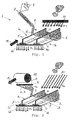
- Fig. 1
- is a schematic perspective view of a system for pre-forming a film or membrane for a vacuum bagging assembly and method according to one embodiment;
- Fig. 2
- is a schematic perspective view of a system for pre-forming a film or membrane for a vacuum bagging system and method according to another embodiment;
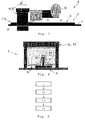
- Fig. 3
- is a schematic side view of a system to pre-form a film or membrane for a vacuum bagging system and method according to a further embodiment;
- Fig. 4
- is a schematic end view of a system for pre-forming a film or membrane for a vacuum bagging system and method according to yet another embodiment; and
- Fig. 5
- is a flow diagram which schematically represents a method of vacuum bagging according to an embodiment of the invention.
- The accompanying drawings are included to provide a further understanding of the present invention and are incorporated in and constitute a part of this specification. The drawings illustrate particular embodiments of the invention and together with the description serve to explain the principles of the invention. Other embodiments of the invention and many of the attendant advantages of the invention will be readily appreciated as they become better understood with reference to the following detailed description.
- It will be appreciated that common and well understood elements that may be useful or necessary in a commercially feasible embodiment are not necessarily depicted in order to facilitate a less abstracted view of the embodiments. The elements of the drawings are not necessarily illustrated to scale relative to each other. It will further be appreciated that certain actions and/or steps in an embodiment of a method may be described or depicted in a particular order of occurrences while those skilled in the art will understand that such specificity with respect to sequence is not actually required. It will also be understood that the terms and expressions used in the present specification have the ordinary meaning as it accorded to such terms and expressions with respect to their corresponding respective areas of enquiry and study, except where specific meanings have otherwise been set forth herein.
- With reference to
Fig. 1 of the drawings, a schematic view of system orassembly 1 for pre-forming a vacuum bagging film ormembrane 2 for use in a vacuum bagging assembly (not shown) according to an embodiment of the invention is illustrated. The vacuum bagging assembly will typically include a moulding tool that forms a base of the assembly. The moulding tool is configured to support the component to be moulded thereon and may comprise a mould or profile for imparting or maintaining a desired form at a side of the component supported thereon. The composite component to be moulded is covered and sealed by the pre-formed film ormembrane 2, and a space between the component and the film or membrane is typically evacuated under a partial vacuum. The partial vacuum is applied during the curing of pre-pregs or wet laid-up fibre-reinforcement of the component covered by the pre-formed film ormembrane 2, or during infusion or impregnation of dry fibre-reinforcement of the component with a polymer resin and then its subsequent curing. - With this embodiment, a significantly improved vacuum bagging assembly is provided via a development of the vacuum bagging film or
membrane 2. Referring toFig. 1 , apre-forming tool 3 for pre-forming the vacuum bagging film ormembrane 2 to a shape or anexternal geometry 4 of the composite component to be moulded is illustrated schematically. In this regard, thepre-forming tool 3 is configured as a replica or reproduction of the shape or theexternal geometry 4 of the component to be moulded. In particular, the shape orexternal geometry 4 of thetool 3 includes the shapes orexternal geometries 5 of a plurality of structural members (e.g. stringers) having a T-section or profile. These stringer shapes orprofiles 5 are arranged extending parallel to one another over the shape orexternal geometry 6 of a panel profile (e.g. skin panel). Thepanel profile 6 of thepre-forming tool 3 in this example is substantially flat, although it could also be curved in other alternative embodiments. -
Fig. 1 of the drawings shows anextruder assembly 7 which is configured to process rawplastic material 8 and to extrude a sheet S of the film ormembrane 2 through a broad slot-like nozzle 9 directly onto thepre-forming tool 3 to cover the shape orexternal geometry 4. In this regard, thetool 3 may be moved in a direction M relative to theextruder assembly 7 to ensure an even distribution of the sheet S of the film ormembrane 2 over the tool. Because the sheet S is extruded at an elevated temperature T+ and is soft as it emerges from theslot nozzle 9 of theextruder assembly 7, it is typically at a temperature suitable for thermoforming as it is applied to thetool 3. To this end, thepre-forming tool 3 is typically also heated to a desired, predetermined temperature T+ to promote the thermoforming. A pressure applicator device in the form of ablower device 10 is configured to apply positive pressure P+ to an upper side orsurface 11 of the film ormembrane 2 to press that film ormembrane 2 against the shape orgeometry 4 of thetool 3. In addition, suction means 12 is provided which cooperates with thetool 13 for generating an under-pressure between thetool 3 and the film ormembrane 2. In this regard, thetool 3 may include holes or apertures for communicating under-pressure generated by the suction means 12 to the film ormembrane 2. - Referring now to
Fig. 2 of the drawings, another embodiment of the system orassembly 1 for pre-forming a vacuum bagging film ormembrane 2 is shown. In this embodiment, the sheet S of the film ormembrane 2 is provided on asupply roll 13 and the sheet S is drawn or extended from thesupply roll 13 over thepre-forming tool 3. The sheet S of the film ormembrane 2 may again be drawn through a slot-like channel 9 within which it may undergo heating T+ before being laid onto and/or over thegeometry 4 of thetool 3. As before, thepre-forming tool 3 is typically heated to a specific desired temperature T+ and the sheet S of the film ormembrane 2 is exposed to both positive pressure P+ fromblower device 10 and under-pressure or negative pressure P- from suction means 12. Accordingly, in each of the embodiments ofFigs. 1 and 2 , the film ormembrane 2 is thermoformed to the shape orgeometry 4 of thetool 3 and which it maintains, i.e. in a relatively stiff or fixed form, upon cooling. - By thermoforming the
film 2 in this way, a pre-formedvacuum bagging film 2 is produced having a predetermined shape or geometry for the vacuum bagging assembly. When a composite component to be moulded is arranged or laid-up in the vacuum bagging assembly of the preferred embodiment and prepared for curing of the pre-impregnated (pre-preg) fibre-reinforcement, or, in the case of a dry lay-up, is prepared for impregnation with a liquid polymer resin and then curing, the composite component has the shape or theexternal geometry 4 of thepre-forming tool 3. Thus, when the vacuum bagging film ormembrane 2 pre-formed according to the method andsystem 1 described above is placed on or over the laid-up component, it is configured to form-fittingly cover the component in the vacuum bagging assembly during the vacuum bagging. As thepre-forming tool 3 corresponds in size and shape to the laid-up composite component to be moulded, thesystem 1 shown in the drawings may be imagined also to correspond essentially in its layout or configuration to a vacuum bagging system or assembly according to the invention. - Referring to
Fig. 3 of the drawings, a schematic side view of asystem 1 for pre-forming a vacuum bagging film ormembrane 2 according to a further embodiment is shown. In this example the sheet S of the film ormembrane 2 is drawn from asupply roll 13 and may be fed and laid over thetool 3 progressively or semi-continuously in conjunction with the movement of a movable pressure chamber 14 and/or movable heating chamber or oven 15 for the localised application of positive pressure P+ and/or heat T+ for pre-forming (e.g. thermoforming) the film ormembrane 2 to the desired shape orgeometry 4.Fig. 4 of the drawings illustrates an end view of a pressure chamber 14 and/or a heating chamber or oven 15 as shown and described with reference toFig. 3 . As shown inFig. 4 , a pressure die 16 may be provided for applying positive pressure via contact with theupper side 11 of thefilm 2 and suction means may be provide to generate a negative pressure P- below thefilm 2. - The
system 1 and method for pre-forming a vacuum bagging film ormembrane 2 as described above may be operated or performed on a continuous basis, e.g. with an essentially continuous sheet S of the film ormembrane 2 from anextruder assembly 7 orsupply roll 13, or on a discontinuous basis, e.g. with discrete or separate sheets S. - With reference now to
Fig. 5 of the drawings, a method of vacuum bagging a fibre-reinforced polymer component, e.g. of an aircraft or spacecraft according to an embodiment is shown schematically, with the numbered boxes I to IV of the diagram representing steps of the method. The first box I represents the step of arranging a component in a vacuum bagging system or assembly, in particular for forming a fibre-reinforced plastic component by resin transfer moulding or impregnating same with a polymer or resin. The second box II represents the step of pre-forming a vacuum bagging film ormembrane 2 to a shape or anexternal geometry 4 of the component to be moulded. As noted above, this may involve thermoforming the film ormembrane 2 on apre-forming tool 3 which has the shape orexternal geometry 4 of the component to be moulded. For example, this may include extruding a sheet or strip S of the film ormembrane 2 or simply drawing such a sheet S of film ormembrane 2 from asupply roll 13 over thetool 3. Further, this step may include heating the film ormembrane 2 to a thermoforming temperature and then applying pressure to press the film ormembrane 2 into contact with thetool 3. The third box III ofFig. 5 represents the step of arranging the pre-formed vacuum bagging film ormembrane 2 on or over the component in the vacuum bagging assembly so that the film ormembrane 2 form-fittingly covers the composite component to be moulded. The fourth box IV then represents the step of either curing the laid-up component comprising prepreg fibre polymer composite, or impregnating the dry fibre-reinforced component with polymer resin in a resin infusion process, and then curing to complete fabrication of the fibre-reinforced polymer component. - Although specific embodiments of the invention have been illustrated and described herein, it will be appreciated by those of ordinary skill in the art that a variety of alternate and/or equivalent implementations exist. It should be appreciated that the exemplary embodiment or exemplary embodiments are only examples, and are not intended to limit the scope, applicability, or configuration in any way. Rather, the foregoing summary and detailed description will provide those skilled in the art with a convenient road map for implementing at least one exemplary embodiment, it being understood that various changes may be made in the function and arrangement of elements described in an exemplary embodiment without departing from the scope as set forth in the appended claims and their legal equivalents. Generally, this application is intended to cover any adaptations or variations of the specific embodiments discussed herein.
- In this document, the terms "comprise", "comprising", "include", "including", "contain", "containing", "have", "having", and any variations thereof, are intended to be understood in an inclusive (i.e. non-exclusive) sense, such that the process, method, device, apparatus or system described herein is not limited to those features or parts or elements or steps recited but may include other elements, features, parts or steps not expressly listed or inherent to such process, method, article, or apparatus. Furthermore, the terms "a" and "an" used herein are intended to be understood as meaning one or more unless explicitly stated otherwise. Moreover, the terms "first", "second", "third", etc. are used merely as labels, and are not intended to impose numerical requirements on or to establish a certain ranking of importance of their objects.
-
- 1
- pre-forming system or assembly
- 2
- vacuum bagging film or membrane
- 3
- pre-forming tool
- 4
- shape or geometry of composite component to be moulded
- 5
- shape or geometry of structural member
- 6
- shape or geometry of panel or skin
- 7
- extruder assembly
- 8
- plastic raw material
- 9
- broad slot-like nozzle
- 10
- blower device
- 11
- upper side or surface of film
- 12
- suction means
- 13
- supply roll
- 14
- pressure chamber
- 15
- oven or autoclave
- 16
- pressure die
- S
- sheet
- M
- movement direction
- P-
- under-pressure or negative pressure
- P+
- positive pressure
- T+
- heating or heating means
Claims (15)
- A vacuum bagging system for vacuum bagging a component, especially a fibre-reinforced polymer component of an aircraft or spacecraft, the system comprising:a vacuum bagging film or membrane (2) configured to cover and seal the component during moulding, especially with prepreg components, wherein the vacuum bagging film or membrane (2) is pre-formed, especially thermoformed, to a shape or an external geometry (4) of the component.
- A system according to claim 1, wherein the component comprises at least one elongate structural member, such as a rib or a stringer, the shape or the external geometry (5) of which is substantially uniform along a length thereof, e.g. a T-section, L-section, C-section, Z-section, Q- or hat-section, or an I-section, and wherein the vacuum bagging film or membrane (2) is pre-formed to the shape or the external geometry (5) of the at least one elongate structural member.
- A system according to claim 2, wherein the component comprises a plurality of elongate structural members and wherein the vacuum bagging film or membrane (2) is pre-formed to the shape or the external geometry (5) of the plurality of elongate structural members.
- A system according to any one of claims 1 to 3, wherein the vacuum bagging film or membrane (2) is provided as a continuous elongate strip or sheet and is pre-formed to the shape or the external geometry (4) of the component over an entire length of the component having a length of over 2 metres, preferably over 10 metres, and more preferably over 20 metres.
- A system according to any one of claims 1 to 4, wherein the vacuum bagging film or membrane (2) is thermoformed to the shape or external geometry of the component under application of pressure, typically differential pressure and/or positive pressure.
- A method of vacuum bagging a component, especially a fibre-reinforced polymer component of an aircraft or spacecraft, comprising the steps of:arranging a component to be moulded in a vacuum bagging assembly for moulding the component;pre-forming a vacuum bagging film or membrane (2) to a shape or an external geometry (4) of the component to be moulded;arranging the vacuum bagging film or membrane (2) on or over the component to be moulded in the vacuum bagging assembly such that the film or membrane (2) form-fittingly covers the component during moulding.
- A method according to claim 6, wherein the step of pre-forming the vacuum bagging film or membrane (5) to the shape or external geometry (4) of the component (2) comprises arranging, and preferably laying, the vacuum bagging film or membrane (2) on or over a pre-forming tool (2) having the shape or external geometry (4) of the component to be moulded.
- A method according to claim 6 or claim 7, wherein the step of pre-forming the vacuum bagging film or membrane to the shape or external geometry (4) of the component comprises thermoforming the film or membrane (2) by applying heat to the film or membrane (5) for softening and forming or shaping same to the external geometry (4) of the component, desirably on the pre-forming tool (2).
- A method according to any one of claims 6 to 8, wherein the step of pre-forming the vacuum bagging film or membrane (2) to the shape or external geometry (4) of the component comprises applying positive pressure to an upper surface (7) of the film or membrane, preferably via a blower device (8) for directing an air stream, e.g. a heated air stream, onto the film or membrane (2) and/or a pressure applicator device (9) for contacting the film or membrane (2) to press same, preferably locally, against the external geometry (4) of the component.
- A method according to any one of claims 6 to 9, wherein the step of pre-forming the vacuum bagging film or membrane (2) to the shape or external geometry (4) of the component includes applying a vacuum to at least partially evacuate a space between the pre-forming tool (2) and the film or membrane (2).
- A method according to any one of claims 6 to 10, wherein the step of arranging or laying the vacuum bagging film or membrane (2) onto or over the pre-forming tool (2) comprises extruding a sheet (S) of the film or membrane (2) onto the tool (2), whereby an extruder assembly (10) may be moved relative to the tool (2) and/or the tool (2) may be moved relative to the extruder assembly (10).
- A method according to any one of claims 6 to 11, wherein the step of arranging or laying the vacuum bagging film or membrane (2) on or over the pre-forming tool (2) comprises drawing or extending a sheet (S) of the film or membrane (2) from a supply roll (11).
- A method according to any of claims 6 to 12, wherein the component comprises at least one elongate structural member, such as a rib or a stringer, the shape or the external geometry (5) of which is substantially uniform along a length thereof, e.g. a T-section, L-section, C-section, Z-section, Ω- or hat-section, or an I-section, wherein the film or membrane (2) is pre-formed to the shape or the external geometry (5) of the at least one elongate structural member.
- A method according to claim 13, wherein the component comprises a plurality of elongate structural members and wherein the vacuum bagging film or membrane (2) is pre-formed to the shape or the external geometry (5) of the plurality of elongate structural members.
- A method according to any of claims 6 to 14, comprising the step of fixing a periphery or an edge region of the film or membrane (2) prior to and/or during the step of pre-forming the film or membrane (2) to the shape or the external geometry (4) of the component.
Priority Applications (4)
| Application Number | Priority Date | Filing Date | Title |
|---|---|---|---|
| EP15175926.3A EP3115184B1 (en) | 2015-07-08 | 2015-07-08 | Improved method for vacuum bagging |
| CA2933935A CA2933935A1 (en) | 2015-07-08 | 2016-06-23 | Improved method and system for vacuum bagging |
| US15/204,575 US10307943B2 (en) | 2015-07-08 | 2016-07-07 | Method and system for vacuum bagging |
| CN201610534756.3A CN106335191B (en) | 2015-07-08 | 2016-07-07 | Improved method and system for vacuum bagging |
Applications Claiming Priority (1)
| Application Number | Priority Date | Filing Date | Title |
|---|---|---|---|
| EP15175926.3A EP3115184B1 (en) | 2015-07-08 | 2015-07-08 | Improved method for vacuum bagging |
Publications (2)
| Publication Number | Publication Date |
|---|---|
| EP3115184A1 true EP3115184A1 (en) | 2017-01-11 |
| EP3115184B1 EP3115184B1 (en) | 2018-09-12 |
Family
ID=53524693
Family Applications (1)
| Application Number | Title | Priority Date | Filing Date |
|---|---|---|---|
| EP15175926.3A Active EP3115184B1 (en) | 2015-07-08 | 2015-07-08 | Improved method for vacuum bagging |
Country Status (4)
| Country | Link |
|---|---|
| US (1) | US10307943B2 (en) |
| EP (1) | EP3115184B1 (en) |
| CN (1) | CN106335191B (en) |
| CA (1) | CA2933935A1 (en) |
Cited By (2)
| Publication number | Priority date | Publication date | Assignee | Title |
|---|---|---|---|---|
| FR3092785A1 (en) | 2019-02-19 | 2020-08-21 | Airbus Operations | method of forming a vacuum bagging film comprising the formation of ribs by buckling the film |
| FR3108871A1 (en) | 2020-04-07 | 2021-10-08 | Airbus Operations | PROCESS FOR MANUFACTURING A PREFORM PACKAGED WITH A COMPONENT IN COMPOSITE MATERIAL AND PROCESS FOR MANUFACTURING THE SAID COMPONENT |
Families Citing this family (5)
| Publication number | Priority date | Publication date | Assignee | Title |
|---|---|---|---|---|
| EP3115184B1 (en) | 2015-07-08 | 2018-09-12 | Airbus Operations GmbH | Improved method for vacuum bagging |
| US10960616B2 (en) * | 2017-08-04 | 2021-03-30 | Industrial Technologies Inc. | Reusable vacuum bag process |
| CN109775047B (en) * | 2019-03-22 | 2023-11-21 | 佛山市科文自动化设备有限公司 | Section bar bagging mechanism |
| JP7124032B2 (en) * | 2020-10-28 | 2022-08-23 | 本田技研工業株式会社 | Molded product manufacturing method |
| US20230191668A1 (en) * | 2021-12-21 | 2023-06-22 | Rohr, Inc. | Non-polyimid based thermoplastic film as vacuum bag material for consolidation of thermoplastic composite materials systems and methods |
Citations (6)
| Publication number | Priority date | Publication date | Assignee | Title |
|---|---|---|---|---|
| US5593633A (en) * | 1990-05-03 | 1997-01-14 | Dull; Kenneth M. | Edge and surface breather for high temperature composite processing |
| US20070175171A1 (en) * | 2005-12-30 | 2007-08-02 | Airbus Espana, S.L. | Process of manufacturing composite panels with U-shaped stiffening members |
| US20080182054A1 (en) * | 2007-01-09 | 2008-07-31 | Ridges Michael D | Multi-function vacuum bag for composite part manufacture |
| US20100170326A1 (en) * | 2006-12-22 | 2010-07-08 | The Boeing Company | Leak detection in composite tools |
| US20120245286A1 (en) * | 2011-03-25 | 2012-09-27 | Bayer Materialscience Llc | Polyurethane composites produced by a vacuum infusion process |
| EP2873516A1 (en) * | 2013-11-19 | 2015-05-20 | Airbus Operations GmbH | Method and arrangement for manufacturing a composite material component |
Family Cites Families (8)
| Publication number | Priority date | Publication date | Assignee | Title |
|---|---|---|---|---|
| US5123985A (en) | 1986-09-02 | 1992-06-23 | Patricia Evans | Vacuum bagging apparatus and method including a thermoplastic elastomer film vacuum bag |
| JP4526698B2 (en) * | 2000-12-22 | 2010-08-18 | 富士重工業株式会社 | COMPOSITE MATERIAL AND MANUFACTURING METHOD THEREOF |
| JP4669031B2 (en) * | 2007-08-22 | 2011-04-13 | 株式会社セイエイ | Molding apparatus and molding method |
| US8628639B2 (en) * | 2011-05-28 | 2014-01-14 | The Boeing Company | Vacuum bag processing using dual seals |
| IN2014DN03149A (en) | 2011-10-26 | 2015-05-22 | Snecma | |
| CN102990944B (en) | 2012-11-16 | 2015-05-13 | 中国航空工业集团公司北京航空材料研究院 | Composite material vacuum bag forming method |
| US20140327190A1 (en) | 2013-05-02 | 2014-11-06 | Gulfstream Aerospace Corporation | Vacuum bag molding assembly and methods |
| EP3115184B1 (en) | 2015-07-08 | 2018-09-12 | Airbus Operations GmbH | Improved method for vacuum bagging |
-
2015
- 2015-07-08 EP EP15175926.3A patent/EP3115184B1/en active Active
-
2016
- 2016-06-23 CA CA2933935A patent/CA2933935A1/en not_active Abandoned
- 2016-07-07 US US15/204,575 patent/US10307943B2/en active Active
- 2016-07-07 CN CN201610534756.3A patent/CN106335191B/en active Active
Patent Citations (6)
| Publication number | Priority date | Publication date | Assignee | Title |
|---|---|---|---|---|
| US5593633A (en) * | 1990-05-03 | 1997-01-14 | Dull; Kenneth M. | Edge and surface breather for high temperature composite processing |
| US20070175171A1 (en) * | 2005-12-30 | 2007-08-02 | Airbus Espana, S.L. | Process of manufacturing composite panels with U-shaped stiffening members |
| US20100170326A1 (en) * | 2006-12-22 | 2010-07-08 | The Boeing Company | Leak detection in composite tools |
| US20080182054A1 (en) * | 2007-01-09 | 2008-07-31 | Ridges Michael D | Multi-function vacuum bag for composite part manufacture |
| US20120245286A1 (en) * | 2011-03-25 | 2012-09-27 | Bayer Materialscience Llc | Polyurethane composites produced by a vacuum infusion process |
| EP2873516A1 (en) * | 2013-11-19 | 2015-05-20 | Airbus Operations GmbH | Method and arrangement for manufacturing a composite material component |
Non-Patent Citations (3)
| Title |
|---|
| ALAN HARPER ET AL: "Reusable Silicone Bags, new analysis report provides Clean bill of health for use in advanced composites", ADVANCED COMPOSITES MANUFACTURING EVENT, PLYMOUTH, 26 SEPTEMBER 2012,, 26 September 2012 (2012-09-26), pages 1 - 39, XP002723449, DOI: HTTP://COMPOSITESGATEWAY.ORG/PRESENTATION/ALAN-ADVANCED-COMPOSITES-MANUF-EVENT.PDF * |
| SMOOTH-ON INC: "How to make a reusable silicone vacuum bag for resin infusion", INTERNET CITATION, 17 October 2011 (2011-10-17), pages 1 - 4, XP002723450, Retrieved from the Internet <URL:https://www.youtube.com/watch?v=XcJ-ErEVrsY#t=43> [retrieved on 20140422] * |
| SMOOTH-ON: "Vacuum Bagging: A new direction", INTERNET, 30 October 2011 (2011-10-30), pages 1 - 3, XP055253695, Retrieved from the Internet <URL:https://web.archive.org/web/20111030115353/http://www.smooth-on.com/Vacuum-Bagging/c1334/index.html> [retrieved on 20160229] * |
Cited By (3)
| Publication number | Priority date | Publication date | Assignee | Title |
|---|---|---|---|---|
| FR3092785A1 (en) | 2019-02-19 | 2020-08-21 | Airbus Operations | method of forming a vacuum bagging film comprising the formation of ribs by buckling the film |
| FR3108871A1 (en) | 2020-04-07 | 2021-10-08 | Airbus Operations | PROCESS FOR MANUFACTURING A PREFORM PACKAGED WITH A COMPONENT IN COMPOSITE MATERIAL AND PROCESS FOR MANUFACTURING THE SAID COMPONENT |
| EP3892450A1 (en) | 2020-04-07 | 2021-10-13 | Airbus Operations (S.A.S.) | Method for manufacturing a preform bag of a component made of composite material and method for manufacturing said component |
Also Published As
| Publication number | Publication date |
|---|---|
| CN106335191A (en) | 2017-01-18 |
| CA2933935A1 (en) | 2017-01-08 |
| US20170008201A1 (en) | 2017-01-12 |
| US10307943B2 (en) | 2019-06-04 |
| EP3115184B1 (en) | 2018-09-12 |
| CN106335191B (en) | 2019-12-13 |
Similar Documents
| Publication | Publication Date | Title |
|---|---|---|
| EP3115184B1 (en) | Improved method for vacuum bagging | |
| US7905975B2 (en) | Process for manufacturing preform and apparatus therefor | |
| EP2116358B1 (en) | Method and apparatus for conforming a blank | |
| US20160332392A1 (en) | Method of forming composite structures | |
| EP2914415B1 (en) | Method and apparatus for forming thermoplastic composite structures | |
| JP6289503B2 (en) | Fabrication of thermoplastic reinforced composite parts | |
| CA2693812C (en) | A method of manufacturing a curved element made of composite material | |
| US20110206906A1 (en) | Continuous Molding of Thermoplastic Laminates | |
| EP1894706A1 (en) | Method for continuously preforming composite material in uncured state | |
| JP2005059260A (en) | Method and apparatus for continuously forming fiber reinforced plastic member having curvature | |
| US20210316479A1 (en) | Method for manufacturing preform, method for manufacturing composite material molded article, and mold | |
| JP5151668B2 (en) | Manufacturing method of FRP | |
| US9994008B2 (en) | Method and system for compacting composite part layup utilizing a single release film layer | |
| US10894344B2 (en) | Forming tool and method for forming a semi-finished product comprising reinforcement fibers and forming apparatus | |
| US20090243151A1 (en) | Method for continuously preforming composite material in uncured state | |
| EP2805802B1 (en) | System and method for producing preforms | |
| US8840828B2 (en) | Hot drape forming by means of a stiffness controlled vacuum bag | |
| EP2868452B1 (en) | System and method for producing composite component | |
| US9724904B2 (en) | Method and system for producing composite component | |
| US11001015B2 (en) | Diaphragm tool for forming reinforcement fiber tiers into preformed t-shaped profiles | |
| US11738525B2 (en) | Composite forming station | |
| US11813807B1 (en) | Glass reinforced polymer composite and method of manufacture | |
| Brooks | Forming technology for thermoplastic composites |
Legal Events
| Date | Code | Title | Description |
|---|---|---|---|
| PUAI | Public reference made under article 153(3) epc to a published international application that has entered the european phase |
Free format text: ORIGINAL CODE: 0009012 |
|
| STAA | Information on the status of an ep patent application or granted ep patent |
Free format text: STATUS: THE APPLICATION HAS BEEN PUBLISHED |
|
| AK | Designated contracting states |
Kind code of ref document: A1 Designated state(s): AL AT BE BG CH CY CZ DE DK EE ES FI FR GB GR HR HU IE IS IT LI LT LU LV MC MK MT NL NO PL PT RO RS SE SI SK SM TR |
|
| AX | Request for extension of the european patent |
Extension state: BA ME |
|
| STAA | Information on the status of an ep patent application or granted ep patent |
Free format text: STATUS: REQUEST FOR EXAMINATION WAS MADE |
|
| 17P | Request for examination filed |
Effective date: 20170531 |
|
| RBV | Designated contracting states (corrected) |
Designated state(s): AL AT BE BG CH CY CZ DE DK EE ES FI FR GB GR HR HU IE IS IT LI LT LU LV MC MK MT NL NO PL PT RO RS SE SI SK SM TR |
|
| GRAP | Despatch of communication of intention to grant a patent |
Free format text: ORIGINAL CODE: EPIDOSNIGR1 |
|
| STAA | Information on the status of an ep patent application or granted ep patent |
Free format text: STATUS: GRANT OF PATENT IS INTENDED |
|
| INTG | Intention to grant announced |
Effective date: 20180410 |
|
| GRAS | Grant fee paid |
Free format text: ORIGINAL CODE: EPIDOSNIGR3 |
|
| GRAA | (expected) grant |
Free format text: ORIGINAL CODE: 0009210 |
|
| STAA | Information on the status of an ep patent application or granted ep patent |
Free format text: STATUS: THE PATENT HAS BEEN GRANTED |
|
| AK | Designated contracting states |
Kind code of ref document: B1 Designated state(s): AL AT BE BG CH CY CZ DE DK EE ES FI FR GB GR HR HU IE IS IT LI LT LU LV MC MK MT NL NO PL PT RO RS SE SI SK SM TR |
|
| REG | Reference to a national code |
Ref country code: GB Ref legal event code: FG4D |
|
| REG | Reference to a national code |
Ref country code: CH Ref legal event code: EP |
|
| REG | Reference to a national code |
Ref country code: IE Ref legal event code: FG4D |
|
| REG | Reference to a national code |
Ref country code: DE Ref legal event code: R096 Ref document number: 602015015974 Country of ref document: DE |
|
| REG | Reference to a national code |
Ref country code: AT Ref legal event code: REF Ref document number: 1040053 Country of ref document: AT Kind code of ref document: T Effective date: 20181015 |
|
| REG | Reference to a national code |
Ref country code: NL Ref legal event code: MP Effective date: 20180912 |
|
| REG | Reference to a national code |
Ref country code: LT Ref legal event code: MG4D |
|
| PG25 | Lapsed in a contracting state [announced via postgrant information from national office to epo] |
Ref country code: NO Free format text: LAPSE BECAUSE OF FAILURE TO SUBMIT A TRANSLATION OF THE DESCRIPTION OR TO PAY THE FEE WITHIN THE PRESCRIBED TIME-LIMIT Effective date: 20181212 Ref country code: GR Free format text: LAPSE BECAUSE OF FAILURE TO SUBMIT A TRANSLATION OF THE DESCRIPTION OR TO PAY THE FEE WITHIN THE PRESCRIBED TIME-LIMIT Effective date: 20181213 Ref country code: SE Free format text: LAPSE BECAUSE OF FAILURE TO SUBMIT A TRANSLATION OF THE DESCRIPTION OR TO PAY THE FEE WITHIN THE PRESCRIBED TIME-LIMIT Effective date: 20180912 Ref country code: FI Free format text: LAPSE BECAUSE OF FAILURE TO SUBMIT A TRANSLATION OF THE DESCRIPTION OR TO PAY THE FEE WITHIN THE PRESCRIBED TIME-LIMIT Effective date: 20180912 Ref country code: LT Free format text: LAPSE BECAUSE OF FAILURE TO SUBMIT A TRANSLATION OF THE DESCRIPTION OR TO PAY THE FEE WITHIN THE PRESCRIBED TIME-LIMIT Effective date: 20180912 Ref country code: RS Free format text: LAPSE BECAUSE OF FAILURE TO SUBMIT A TRANSLATION OF THE DESCRIPTION OR TO PAY THE FEE WITHIN THE PRESCRIBED TIME-LIMIT Effective date: 20180912 Ref country code: BG Free format text: LAPSE BECAUSE OF FAILURE TO SUBMIT A TRANSLATION OF THE DESCRIPTION OR TO PAY THE FEE WITHIN THE PRESCRIBED TIME-LIMIT Effective date: 20181212 |
|
| PG25 | Lapsed in a contracting state [announced via postgrant information from national office to epo] |
Ref country code: AL Free format text: LAPSE BECAUSE OF FAILURE TO SUBMIT A TRANSLATION OF THE DESCRIPTION OR TO PAY THE FEE WITHIN THE PRESCRIBED TIME-LIMIT Effective date: 20180912 Ref country code: LV Free format text: LAPSE BECAUSE OF FAILURE TO SUBMIT A TRANSLATION OF THE DESCRIPTION OR TO PAY THE FEE WITHIN THE PRESCRIBED TIME-LIMIT Effective date: 20180912 Ref country code: HR Free format text: LAPSE BECAUSE OF FAILURE TO SUBMIT A TRANSLATION OF THE DESCRIPTION OR TO PAY THE FEE WITHIN THE PRESCRIBED TIME-LIMIT Effective date: 20180912 |
|
| REG | Reference to a national code |
Ref country code: AT Ref legal event code: MK05 Ref document number: 1040053 Country of ref document: AT Kind code of ref document: T Effective date: 20180912 |
|
| PG25 | Lapsed in a contracting state [announced via postgrant information from national office to epo] |
Ref country code: PL Free format text: LAPSE BECAUSE OF FAILURE TO SUBMIT A TRANSLATION OF THE DESCRIPTION OR TO PAY THE FEE WITHIN THE PRESCRIBED TIME-LIMIT Effective date: 20180912 Ref country code: AT Free format text: LAPSE BECAUSE OF FAILURE TO SUBMIT A TRANSLATION OF THE DESCRIPTION OR TO PAY THE FEE WITHIN THE PRESCRIBED TIME-LIMIT Effective date: 20180912 Ref country code: EE Free format text: LAPSE BECAUSE OF FAILURE TO SUBMIT A TRANSLATION OF THE DESCRIPTION OR TO PAY THE FEE WITHIN THE PRESCRIBED TIME-LIMIT Effective date: 20180912 Ref country code: IS Free format text: LAPSE BECAUSE OF FAILURE TO SUBMIT A TRANSLATION OF THE DESCRIPTION OR TO PAY THE FEE WITHIN THE PRESCRIBED TIME-LIMIT Effective date: 20190112 Ref country code: ES Free format text: LAPSE BECAUSE OF FAILURE TO SUBMIT A TRANSLATION OF THE DESCRIPTION OR TO PAY THE FEE WITHIN THE PRESCRIBED TIME-LIMIT Effective date: 20180912 Ref country code: CZ Free format text: LAPSE BECAUSE OF FAILURE TO SUBMIT A TRANSLATION OF THE DESCRIPTION OR TO PAY THE FEE WITHIN THE PRESCRIBED TIME-LIMIT Effective date: 20180912 Ref country code: RO Free format text: LAPSE BECAUSE OF FAILURE TO SUBMIT A TRANSLATION OF THE DESCRIPTION OR TO PAY THE FEE WITHIN THE PRESCRIBED TIME-LIMIT Effective date: 20180912 Ref country code: NL Free format text: LAPSE BECAUSE OF FAILURE TO SUBMIT A TRANSLATION OF THE DESCRIPTION OR TO PAY THE FEE WITHIN THE PRESCRIBED TIME-LIMIT Effective date: 20180912 Ref country code: IT Free format text: LAPSE BECAUSE OF FAILURE TO SUBMIT A TRANSLATION OF THE DESCRIPTION OR TO PAY THE FEE WITHIN THE PRESCRIBED TIME-LIMIT Effective date: 20180912 |
|
| PG25 | Lapsed in a contracting state [announced via postgrant information from national office to epo] |
Ref country code: SK Free format text: LAPSE BECAUSE OF FAILURE TO SUBMIT A TRANSLATION OF THE DESCRIPTION OR TO PAY THE FEE WITHIN THE PRESCRIBED TIME-LIMIT Effective date: 20180912 Ref country code: PT Free format text: LAPSE BECAUSE OF FAILURE TO SUBMIT A TRANSLATION OF THE DESCRIPTION OR TO PAY THE FEE WITHIN THE PRESCRIBED TIME-LIMIT Effective date: 20190112 Ref country code: SM Free format text: LAPSE BECAUSE OF FAILURE TO SUBMIT A TRANSLATION OF THE DESCRIPTION OR TO PAY THE FEE WITHIN THE PRESCRIBED TIME-LIMIT Effective date: 20180912 |
|
| REG | Reference to a national code |
Ref country code: DE Ref legal event code: R097 Ref document number: 602015015974 Country of ref document: DE |
|
| PLBE | No opposition filed within time limit |
Free format text: ORIGINAL CODE: 0009261 |
|
| STAA | Information on the status of an ep patent application or granted ep patent |
Free format text: STATUS: NO OPPOSITION FILED WITHIN TIME LIMIT |
|
| PG25 | Lapsed in a contracting state [announced via postgrant information from national office to epo] |
Ref country code: DK Free format text: LAPSE BECAUSE OF FAILURE TO SUBMIT A TRANSLATION OF THE DESCRIPTION OR TO PAY THE FEE WITHIN THE PRESCRIBED TIME-LIMIT Effective date: 20180912 |
|
| 26N | No opposition filed |
Effective date: 20190613 |
|
| PG25 | Lapsed in a contracting state [announced via postgrant information from national office to epo] |
Ref country code: SI Free format text: LAPSE BECAUSE OF FAILURE TO SUBMIT A TRANSLATION OF THE DESCRIPTION OR TO PAY THE FEE WITHIN THE PRESCRIBED TIME-LIMIT Effective date: 20180912 |
|
| PG25 | Lapsed in a contracting state [announced via postgrant information from national office to epo] |
Ref country code: MC Free format text: LAPSE BECAUSE OF FAILURE TO SUBMIT A TRANSLATION OF THE DESCRIPTION OR TO PAY THE FEE WITHIN THE PRESCRIBED TIME-LIMIT Effective date: 20180912 |
|
| REG | Reference to a national code |
Ref country code: CH Ref legal event code: PL |
|
| PG25 | Lapsed in a contracting state [announced via postgrant information from national office to epo] |
Ref country code: TR Free format text: LAPSE BECAUSE OF FAILURE TO SUBMIT A TRANSLATION OF THE DESCRIPTION OR TO PAY THE FEE WITHIN THE PRESCRIBED TIME-LIMIT Effective date: 20180912 |
|
| REG | Reference to a national code |
Ref country code: BE Ref legal event code: MM Effective date: 20190731 |
|
| PG25 | Lapsed in a contracting state [announced via postgrant information from national office to epo] |
Ref country code: CH Free format text: LAPSE BECAUSE OF NON-PAYMENT OF DUE FEES Effective date: 20190731 Ref country code: BE Free format text: LAPSE BECAUSE OF NON-PAYMENT OF DUE FEES Effective date: 20190731 Ref country code: LU Free format text: LAPSE BECAUSE OF NON-PAYMENT OF DUE FEES Effective date: 20190708 Ref country code: LI Free format text: LAPSE BECAUSE OF NON-PAYMENT OF DUE FEES Effective date: 20190731 |
|
| PG25 | Lapsed in a contracting state [announced via postgrant information from national office to epo] |
Ref country code: IE Free format text: LAPSE BECAUSE OF NON-PAYMENT OF DUE FEES Effective date: 20190708 |
|
| PG25 | Lapsed in a contracting state [announced via postgrant information from national office to epo] |
Ref country code: CY Free format text: LAPSE BECAUSE OF FAILURE TO SUBMIT A TRANSLATION OF THE DESCRIPTION OR TO PAY THE FEE WITHIN THE PRESCRIBED TIME-LIMIT Effective date: 20180912 |
|
| PG25 | Lapsed in a contracting state [announced via postgrant information from national office to epo] |
Ref country code: HU Free format text: LAPSE BECAUSE OF FAILURE TO SUBMIT A TRANSLATION OF THE DESCRIPTION OR TO PAY THE FEE WITHIN THE PRESCRIBED TIME-LIMIT; INVALID AB INITIO Effective date: 20150708 Ref country code: MT Free format text: LAPSE BECAUSE OF FAILURE TO SUBMIT A TRANSLATION OF THE DESCRIPTION OR TO PAY THE FEE WITHIN THE PRESCRIBED TIME-LIMIT Effective date: 20180912 |
|
| PG25 | Lapsed in a contracting state [announced via postgrant information from national office to epo] |
Ref country code: MK Free format text: LAPSE BECAUSE OF FAILURE TO SUBMIT A TRANSLATION OF THE DESCRIPTION OR TO PAY THE FEE WITHIN THE PRESCRIBED TIME-LIMIT Effective date: 20180912 |
|
| PGFP | Annual fee paid to national office [announced via postgrant information from national office to epo] |
Ref country code: FR Payment date: 20220720 Year of fee payment: 8 |
|
| PGFP | Annual fee paid to national office [announced via postgrant information from national office to epo] |
Ref country code: GB Payment date: 20230721 Year of fee payment: 9 |
|
| PGFP | Annual fee paid to national office [announced via postgrant information from national office to epo] |
Ref country code: DE Payment date: 20230719 Year of fee payment: 9 |