EP3115177B1 - Deposition nozzle and, system and method for creating polymer composites with aligned and oriented fibers - Google Patents
Deposition nozzle and, system and method for creating polymer composites with aligned and oriented fibers Download PDFInfo
- Publication number
- EP3115177B1 EP3115177B1 EP16176495.6A EP16176495A EP3115177B1 EP 3115177 B1 EP3115177 B1 EP 3115177B1 EP 16176495 A EP16176495 A EP 16176495A EP 3115177 B1 EP3115177 B1 EP 3115177B1
- Authority
- EP
- European Patent Office
- Prior art keywords
- fibers
- deposition nozzle
- housing
- solution
- aligned
- Prior art date
- Legal status (The legal status is an assumption and is not a legal conclusion. Google has not performed a legal analysis and makes no representation as to the accuracy of the status listed.)
- Active
Links
Images


Classifications
-
- B—PERFORMING OPERATIONS; TRANSPORTING
- B29—WORKING OF PLASTICS; WORKING OF SUBSTANCES IN A PLASTIC STATE IN GENERAL
- B29B—PREPARATION OR PRETREATMENT OF THE MATERIAL TO BE SHAPED; MAKING GRANULES OR PREFORMS; RECOVERY OF PLASTICS OR OTHER CONSTITUENTS OF WASTE MATERIAL CONTAINING PLASTICS
- B29B11/00—Making preforms
- B29B11/14—Making preforms characterised by structure or composition
- B29B11/16—Making preforms characterised by structure or composition comprising fillers or reinforcement
-
- B—PERFORMING OPERATIONS; TRANSPORTING
- B05—SPRAYING OR ATOMISING IN GENERAL; APPLYING FLUENT MATERIALS TO SURFACES, IN GENERAL
- B05C—APPARATUS FOR APPLYING FLUENT MATERIALS TO SURFACES, IN GENERAL
- B05C19/00—Apparatus specially adapted for applying particulate materials to surfaces
- B05C19/06—Storage, supply or control of the application of particulate material; Recovery of excess particulate material
-
- B—PERFORMING OPERATIONS; TRANSPORTING
- B05—SPRAYING OR ATOMISING IN GENERAL; APPLYING FLUENT MATERIALS TO SURFACES, IN GENERAL
- B05D—PROCESSES FOR APPLYING FLUENT MATERIALS TO SURFACES, IN GENERAL
- B05D3/00—Pretreatment of surfaces to which liquids or other fluent materials are to be applied; After-treatment of applied coatings, e.g. intermediate treating of an applied coating preparatory to subsequent applications of liquids or other fluent materials
- B05D3/04—Pretreatment of surfaces to which liquids or other fluent materials are to be applied; After-treatment of applied coatings, e.g. intermediate treating of an applied coating preparatory to subsequent applications of liquids or other fluent materials by exposure to gases
- B05D3/0493—Pretreatment of surfaces to which liquids or other fluent materials are to be applied; After-treatment of applied coatings, e.g. intermediate treating of an applied coating preparatory to subsequent applications of liquids or other fluent materials by exposure to gases using vacuum
-
- B—PERFORMING OPERATIONS; TRANSPORTING
- B29—WORKING OF PLASTICS; WORKING OF SUBSTANCES IN A PLASTIC STATE IN GENERAL
- B29C—SHAPING OR JOINING OF PLASTICS; SHAPING OF MATERIAL IN A PLASTIC STATE, NOT OTHERWISE PROVIDED FOR; AFTER-TREATMENT OF THE SHAPED PRODUCTS, e.g. REPAIRING
- B29C41/00—Shaping by coating a mould, core or other substrate, i.e. by depositing material and stripping-off the shaped article; Apparatus therefor
- B29C41/02—Shaping by coating a mould, core or other substrate, i.e. by depositing material and stripping-off the shaped article; Apparatus therefor for making articles of definite length, i.e. discrete articles
- B29C41/16—Slip casting, i.e. applying a slip or slurry on a perforated or porous or absorbent surface with the liquid being drained away
-
- B—PERFORMING OPERATIONS; TRANSPORTING
- B29—WORKING OF PLASTICS; WORKING OF SUBSTANCES IN A PLASTIC STATE IN GENERAL
- B29C—SHAPING OR JOINING OF PLASTICS; SHAPING OF MATERIAL IN A PLASTIC STATE, NOT OTHERWISE PROVIDED FOR; AFTER-TREATMENT OF THE SHAPED PRODUCTS, e.g. REPAIRING
- B29C48/00—Extrusion moulding, i.e. expressing the moulding material through a die or nozzle which imparts the desired form; Apparatus therefor
- B29C48/25—Component parts, details or accessories; Auxiliary operations
- B29C48/30—Extrusion nozzles or dies
- B29C48/35—Extrusion nozzles or dies with rollers
-
- B—PERFORMING OPERATIONS; TRANSPORTING
- B29—WORKING OF PLASTICS; WORKING OF SUBSTANCES IN A PLASTIC STATE IN GENERAL
- B29C—SHAPING OR JOINING OF PLASTICS; SHAPING OF MATERIAL IN A PLASTIC STATE, NOT OTHERWISE PROVIDED FOR; AFTER-TREATMENT OF THE SHAPED PRODUCTS, e.g. REPAIRING
- B29C70/00—Shaping composites, i.e. plastics material comprising reinforcements, fillers or preformed parts, e.g. inserts
- B29C70/04—Shaping composites, i.e. plastics material comprising reinforcements, fillers or preformed parts, e.g. inserts comprising reinforcements only, e.g. self-reinforcing plastics
- B29C70/06—Fibrous reinforcements only
- B29C70/10—Fibrous reinforcements only characterised by the structure of fibrous reinforcements, e.g. hollow fibres
- B29C70/12—Fibrous reinforcements only characterised by the structure of fibrous reinforcements, e.g. hollow fibres using fibres of short length, e.g. in the form of a mat
- B29C70/14—Fibrous reinforcements only characterised by the structure of fibrous reinforcements, e.g. hollow fibres using fibres of short length, e.g. in the form of a mat oriented
-
- B—PERFORMING OPERATIONS; TRANSPORTING
- B29—WORKING OF PLASTICS; WORKING OF SUBSTANCES IN A PLASTIC STATE IN GENERAL
- B29C—SHAPING OR JOINING OF PLASTICS; SHAPING OF MATERIAL IN A PLASTIC STATE, NOT OTHERWISE PROVIDED FOR; AFTER-TREATMENT OF THE SHAPED PRODUCTS, e.g. REPAIRING
- B29C70/00—Shaping composites, i.e. plastics material comprising reinforcements, fillers or preformed parts, e.g. inserts
- B29C70/04—Shaping composites, i.e. plastics material comprising reinforcements, fillers or preformed parts, e.g. inserts comprising reinforcements only, e.g. self-reinforcing plastics
- B29C70/28—Shaping operations therefor
- B29C70/30—Shaping by lay-up, i.e. applying fibres, tape or broadsheet on a mould, former or core; Shaping by spray-up, i.e. spraying of fibres on a mould, former or core
- B29C70/38—Automated lay-up, e.g. using robots, laying filaments according to predetermined patterns
- B29C70/382—Automated fiber placement [AFP]
- B29C70/384—Fiber placement heads, e.g. component parts, details or accessories
-
- B—PERFORMING OPERATIONS; TRANSPORTING
- B29—WORKING OF PLASTICS; WORKING OF SUBSTANCES IN A PLASTIC STATE IN GENERAL
- B29C—SHAPING OR JOINING OF PLASTICS; SHAPING OF MATERIAL IN A PLASTIC STATE, NOT OTHERWISE PROVIDED FOR; AFTER-TREATMENT OF THE SHAPED PRODUCTS, e.g. REPAIRING
- B29C70/00—Shaping composites, i.e. plastics material comprising reinforcements, fillers or preformed parts, e.g. inserts
- B29C70/04—Shaping composites, i.e. plastics material comprising reinforcements, fillers or preformed parts, e.g. inserts comprising reinforcements only, e.g. self-reinforcing plastics
- B29C70/28—Shaping operations therefor
- B29C70/40—Shaping or impregnating by compression not applied
- B29C70/42—Shaping or impregnating by compression not applied for producing articles of definite length, i.e. discrete articles
- B29C70/46—Shaping or impregnating by compression not applied for producing articles of definite length, i.e. discrete articles using matched moulds, e.g. for deforming sheet moulding compounds [SMC] or prepregs
- B29C70/48—Shaping or impregnating by compression not applied for producing articles of definite length, i.e. discrete articles using matched moulds, e.g. for deforming sheet moulding compounds [SMC] or prepregs and impregnating the reinforcements in the closed mould, e.g. resin transfer moulding [RTM], e.g. by vacuum
-
- D—TEXTILES; PAPER
- D04—BRAIDING; LACE-MAKING; KNITTING; TRIMMINGS; NON-WOVEN FABRICS
- D04H—MAKING TEXTILE FABRICS, e.g. FROM FIBRES OR FILAMENTARY MATERIAL; FABRICS MADE BY SUCH PROCESSES OR APPARATUS, e.g. FELTS, NON-WOVEN FABRICS; COTTON-WOOL; WADDING ; NON-WOVEN FABRICS FROM STAPLE FIBRES, FILAMENTS OR YARNS, BONDED WITH AT LEAST ONE WEB-LIKE MATERIAL DURING THEIR CONSOLIDATION
- D04H1/00—Non-woven fabrics formed wholly or mainly of staple fibres or like relatively short fibres
- D04H1/70—Non-woven fabrics formed wholly or mainly of staple fibres or like relatively short fibres characterised by the method of forming fleeces or layers, e.g. reorientation of fibres
- D04H1/74—Non-woven fabrics formed wholly or mainly of staple fibres or like relatively short fibres characterised by the method of forming fleeces or layers, e.g. reorientation of fibres the fibres being orientated, e.g. in parallel (anisotropic fleeces)
-
- B—PERFORMING OPERATIONS; TRANSPORTING
- B29—WORKING OF PLASTICS; WORKING OF SUBSTANCES IN A PLASTIC STATE IN GENERAL
- B29C—SHAPING OR JOINING OF PLASTICS; SHAPING OF MATERIAL IN A PLASTIC STATE, NOT OTHERWISE PROVIDED FOR; AFTER-TREATMENT OF THE SHAPED PRODUCTS, e.g. REPAIRING
- B29C48/00—Extrusion moulding, i.e. expressing the moulding material through a die or nozzle which imparts the desired form; Apparatus therefor
- B29C48/25—Component parts, details or accessories; Auxiliary operations
- B29C48/285—Feeding the extrusion material to the extruder
- B29C48/288—Feeding the extrusion material to the extruder in solid form, e.g. powder or granules
- B29C48/2886—Feeding the extrusion material to the extruder in solid form, e.g. powder or granules of fibrous, filamentary or filling materials, e.g. thin fibrous reinforcements or fillers
-
- D—TEXTILES; PAPER
- D04—BRAIDING; LACE-MAKING; KNITTING; TRIMMINGS; NON-WOVEN FABRICS
- D04H—MAKING TEXTILE FABRICS, e.g. FROM FIBRES OR FILAMENTARY MATERIAL; FABRICS MADE BY SUCH PROCESSES OR APPARATUS, e.g. FELTS, NON-WOVEN FABRICS; COTTON-WOOL; WADDING ; NON-WOVEN FABRICS FROM STAPLE FIBRES, FILAMENTS OR YARNS, BONDED WITH AT LEAST ONE WEB-LIKE MATERIAL DURING THEIR CONSOLIDATION
- D04H1/00—Non-woven fabrics formed wholly or mainly of staple fibres or like relatively short fibres
- D04H1/70—Non-woven fabrics formed wholly or mainly of staple fibres or like relatively short fibres characterised by the method of forming fleeces or layers, e.g. reorientation of fibres
Definitions
- the disclosure here relates to a deposition nozzle, a system and a method for producing fiber composite sheets, more particularly to aligned and arbitrarily oriented fiber reinforced fiber composite sheets.
- Manufacturing processes may employ fiber preforms.
- the preforms typically consist of sheets or mats of fibers.
- the mats are shaped into desired forms or inserted into molds as a matrix.
- Polymer materials are then infused into the matrix and the desired article is formed.
- the article is then hardened and removed from the mold.
- Formation of the fiber preforms typically involves a complicated, expensive process with expensive equipment.
- One challenge lies in attempts to orient the fibers in a desired direction for better strength.
- Advances in printing technology may hold the answer to reducing the costs and complexity of the process while also allowing for better alignment of the fibers, but to date no such approach exists.
- US 3617437 describes a process for manufacturing a matrix of aligned fibers which includes the steps of dispersing the fibers in a viscous liquid, passing the dispersion through an orifice so that the fibers are at least partially aligned, and laying the dispersion containing aligned fibers upon a permeable surface moving relative to the orifice.
- DE 10053622 describes an apparatus for the production of fiber webs that consists of a feed chute, a fiber separator and a discharge nozzle.
- One embodiment consists of a deposition nozzle having a housing, an inlet into the housing arranged to receive a solution carrying randomly oriented fibers, an orientation component within the housing, the orientation component positioned to receive the solution from the inlet and operate to produce aligned fibers in a predetermined, single direction, and an outlet on the housing arranged to receive the aligned fibers and deposit them on a substrate.
- Another embodiment consists of a system including a porous substrate, a deposition nozzle, a reservoir of randomly oriented fibers in solution connected to the deposition nozzle, the nozzle to receive the randomly oriented fibers and output aligned fibers, and a vacuum connected to the porous substrate to remove fluid from the porous substrate as the deposition nozzle deposits the aligned fibers on the porous substrate to produce a fiber pre-form having aligned fibers.
- Another embodiment consists of a method including providing a reservoir of randomly oriented fibers in a solution, dispensing the solution of randomly oriented fibers through a nozzle having an orientation component onto a porous substrate as a solution of aligned fibers, and immobilizing the fibers to form a fiber pre-form.
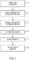
- Figures 1 and 2 show an embodiment of a system and method to create oriented fiber preforms and then subsequently using that preform to produce a fiber reinforced composite.
- a fiber suspension in a fluid is created at 10.
- the suspension may consist of a low-volume fraction of a fibers dispersed in a solution.
- the solution may consist of a Newtonian fluid.
- the solution may include a binder.
- the system 30 includes a reservoir 32 to hold the suspension.
- a fiber orientation and alignment head shown at 34 in Figure 2 , dispenses the fiber suspension onto a substrate of some sort.
- the substrate 38 is a perforated and/or porous substrate held by a fixture 36.
- the substrate may be mounted or otherwise connected to an aspiration system such as a vacuum.
- An aspiration device such as vacuum 40 removes extra fluid from the suspension to leave the fibers behind. This results in a high fractional composition fiber mat.
- the preform undergoes some sort of immobilization or adhering process at 14 to fix the fibers in place and solidify or semi-solidify the preform.
- the immobilization may involve a binder in the solution, as discussed above, as the solution is removed, the binder stays behind and fixes the fibers in place.
- an adhesive or binder may be sprayed onto the preform.
- the embodiments here are directed to the formation of the preform with oriented fibers formed using a unique fiber orientation head. Once manufactured, this preform may receive a matrix of polymer/resin to form a fiber reinforced composite. For completeness, this discussion sets out embodiments of how to perform an infiltration of the matrix into the preform, with the understanding that this process is optional and may take many different forms.
- the preform receives the matrix at 16 in Figure 1 .
- the matrix may consist of many different materials, including but not limited to, various types of polymers such as resins, polyurethane compounds, etc. and may be in liquid form or take the form of sheets of thermoplastic or other moldable materials. Many different types of materials can be used. In general, any material that is used for Resin Transfer Molding (RTM) or Resin Infusion Molding (RIM) could be used.
- RTM Resin Transfer Molding
- RIM Resin Infusion Molding
- the key is to adjust the viscosity and curing properties to make them compatible with the infusion process, and this would depend on the particular pre-form that is made. Typical viscosities are in the range 50-1000 centipose.
- Common RTM and RIM materials include: unsaturated polyesters, vinyl esters, epoxies, polyimides, phenolics, etc. It may be possible to use thermoplastics if adjustments are made for their high viscosity. The process needs to control the temperature well enough to achieve a reasonably low viscosity. Common thermoplastics include: polypropylene, nylon, polycarbonate, polyethylene terephthalate (PET), acrylonitrile-butadiene-styrene (ABS), etc. In the example of Figure 2 , the matrix is fed into the preform as a liquid through the feed mechanism 44.
- the infiltration process results in a wet matrix contained by the fiber preform.
- This structure requires setting to form a finished reinforced fiber composite.
- the setting operation may involve the application of heat and/or pressure, then a cooling process to solidify the matrix with the preform at 18 in Figure 1 .
- the post-processing will depend on the material that is infused. At 20 in Figure 1 , this results in a fiber reinforced composite 42 in Figure 13 .
- FIG. 2 shows an example of a mechanical four roll mill.
- the mechanical four roll mill has two inlets 41 and 43. The 4 rolls of the mill counter rotate, pushing the liquids out the outlets 45 and 47. This type of extensional flow from the outlets causes fibers in the suspension to align.
- FIG 4 shows one embodiment of a fiber alignment head, which may be referred to as a fiber alignment and orientation head.
- the alignment head has a housing 35 that contains the orientation component, discussed in more detail later.
- the housing 35 has a rotating ring 48 that can control the angle of the alignment of the fibers as they exit the head.
- the housing contains a 2-roll mill. The suspension with the fibers flows from the bottom of the housing as shown in the drawing, into the 2-roll mill. The motion of the rollers causes the fibers to align as they exit the outlet 48.
- the flows may be better understood looking at the flow diagram of Figure 5 .
- the housing 34 has an inlet flow 52 that narrows into a path 54 between rolls and then exits the print head as an aligned flow.
- the rollers create a splaying flow as shown in Figure 6 .
- the rollers cause the fibers to align between then in the region 54 and then exit the mill in a flow 60.
- the head has a rotational ring 48 at the outlet.
- the rotation can alter the angle for the fibers as they exit the head.
- Figures 7-9 show different possibilities.
- the fibers are aligned horizontally relative to the picture.
- the exit angle for the fiber changes.
- Figure 8 shows a first exit angle that comes from a first rotation rate
- Figure 9 shows a second exit angle that comes from a second rotation rate.
- Different applications may have different preforms with different angles and different structural aspects. The ability to rotate the output allows for better control of the fiber orientation.
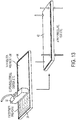
- FIG. 10 shows an alternative housing 70.
- the housing has a cylindrical portion 72, which narrows down into the output portion 74.
- the dimensions of the output portion get larger or 'wider' in the direction of the flows shown by the arrow, but get smaller orthogonal to the flow direction.
- the resulting output portion has a larger dimension left to right on the page than the cylindrical portion, but is much narrower going into and out of the page. This results in the output portion of the housing being not much wider than the width of the slit 76.
- Figure 10 shows the details of the inside of the housing of this alternative alignment head as well as the addition of a recycling flow.
- the inlet narrows to a contraction 78.
- the contraction 78 forces the fibers within the solution to begin to align parallel to the flow axis. This guarantees that all fibers exit in the center of the nozzle and have the same starting orientation before processing to the expansion portion 74.
- the contraction is followed by the expansion outlet portion 74.
- the outlet portion widens in one direction over the contraction 78, but narrows in a dimension orthogonal to the widening direction. This causes alignment orthogonal to the flow axis.
- the alignment head may have a recycling flow outlet 84 that applies negative pressure to pull the flow in the direction shown by the arrows 86 and 88. This will be referred to the recycling or secondary flow.
- the main flow moves out of the nozzle in the direction of the arrow 80.
- the recycling flow assists in the alignment of the fibers as they exit the head. This enhances the splaying flow discussed above.
- the preform may need to undergo further processing prior to the infiltration with the matrix.
- vacuum pressure will serve to compress and immobilize the deposited fibers and remove the carrier fluid.
- the fibers may undergo further immobilization.
- the solution may include a binder that holds the fibers in place when the fluid is removed.
- the fiber preform may be sprayed or otherwise coated at least partially with a binder solution. The binder may facilitate handling of the fiber perform for the next processing step. It may also improve the thermoplastic interface quality of the preform when it is infiltrated with the matrix.
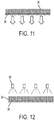
- Figure 11 shows a side view of the fiber preform 39 as it undergoes deposition with an applied vacuum.
- the substrate 38 is porous, which allows the vacuum to act on the preform.
- spray heads such as 90 dispense the binder solution onto the preform.
- the binder may need to undergo a further setting process such as drying or application of heat.
- the preform with the oriented fibers may be infiltrated with a matrix.
- a matrix One embodiment of such a process is shown in Figure 13 .
- the fiber preform 39 may be coated or infiltrated with a molten polymer or resin 94 using an applicator 92 such as a curtain, slot, roll coater, etc.
- the matrix may solidify merely by allowing it to cool and/or dry. Alternatively, the matrix may require the application of heat and pressure as shown in Figure 13 , resulting in the fiber reinforced composite 42.
- a unique nozzle allows for orientation of fibers in a solution to create a fiber preform.
- the preform may have fibers orientated according to the form needed.
- the resulting fiber reinforced composite material or shape After infiltration of the matrix, the resulting fiber reinforced composite material or shape has superior strength and the nozzle enables relatively inexpensive, relatively simple manufacturing.
Description
- The disclosure here relates to a deposition nozzle, a system and a method for producing fiber composite sheets, more particularly to aligned and arbitrarily oriented fiber reinforced fiber composite sheets.
- Manufacturing processes may employ fiber preforms. The preforms typically consist of sheets or mats of fibers. The mats are shaped into desired forms or inserted into molds as a matrix. Polymer materials are then infused into the matrix and the desired article is formed. The article is then hardened and removed from the mold.
- Formation of the fiber preforms typically involves a complicated, expensive process with expensive equipment. One challenge lies in attempts to orient the fibers in a desired direction for better strength. Advances in printing technology may hold the answer to reducing the costs and complexity of the process while also allowing for better alignment of the fibers, but to date no such approach exists.
-
US 3617437 describes a process for manufacturing a matrix of aligned fibers which includes the steps of dispersing the fibers in a viscous liquid, passing the dispersion through an orifice so that the fibers are at least partially aligned, and laying the dispersion containing aligned fibers upon a permeable surface moving relative to the orifice. -
DE 10053622 describes an apparatus for the production of fiber webs that consists of a feed chute, a fiber separator and a discharge nozzle. - One embodiment consists of a deposition nozzle having a housing, an inlet into the housing arranged to receive a solution carrying randomly oriented fibers, an orientation component within the housing, the orientation component positioned to receive the solution from the inlet and operate to produce aligned fibers in a predetermined, single direction, and an outlet on the housing arranged to receive the aligned fibers and deposit them on a substrate.
- Another embodiment consists of a system including a porous substrate, a deposition nozzle, a reservoir of randomly oriented fibers in solution connected to the deposition nozzle, the nozzle to receive the randomly oriented fibers and output aligned fibers, and a vacuum connected to the porous substrate to remove fluid from the porous substrate as the deposition nozzle deposits the aligned fibers on the porous substrate to produce a fiber pre-form having aligned fibers.
- Another embodiment consists of a method including providing a reservoir of randomly oriented fibers in a solution, dispensing the solution of randomly oriented fibers through a nozzle having an orientation component onto a porous substrate as a solution of aligned fibers, and immobilizing the fibers to form a fiber pre-form.
-
-
Figure 1 shows a flowchart of an embodiment of a method to produce a fiber reinforced composite from a preform with oriented fibers. -
Figure 2 show an embodiment of a system to produce a fiber reinforced composite from a preform with oriented fibers. -
Figure 3 shows an embodiment of a four-roll mill. -
Figure 4 shows an embodiment of a fiber orientation and alignment head with a two-roll mill. -
Figure 5 shows a representation of an orthogonal extensional flow. -
Figure 6 shows an alternative representation of an orthogonal extensional flow. -
Figures 7-9 show embodiments of changing angles of fibers from an orientation and alignment head. -
Figure 10 shows an alternative embodiment of a fiber orientation and alignment head with recycling flow. -
Figures 11-12 show an embodiment of fiber immobilization. -
Figure 13 shows an embodiment of a method to infiltrate a fiber preform with a matrix. -
Figures 1 and2 show an embodiment of a system and method to create oriented fiber preforms and then subsequently using that preform to produce a fiber reinforced composite. - The discussion of
Figure 1 will be in conjunction with other drawings to provide information about the embodiments and variations in the system. - At an initial part of the process, a fiber suspension in a fluid is created at 10. The suspension may consist of a low-volume fraction of a fibers dispersed in a solution. In one embodiment, the solution may consist of a Newtonian fluid. In one embodiment, the solution may include a binder. In the system diagram of
Figure 2 , thesystem 30 includes areservoir 32 to hold the suspension. - At 12, a fiber orientation and alignment head, show at 34 in
Figure 2 , dispenses the fiber suspension onto a substrate of some sort. In one embodiment, shown inFigure 2 , thesubstrate 38 is a perforated and/or porous substrate held by afixture 36. The substrate may be mounted or otherwise connected to an aspiration system such as a vacuum. An aspiration device such asvacuum 40 removes extra fluid from the suspension to leave the fibers behind. This results in a high fractional composition fiber mat. - Once the solution has been dispensed to sufficiently build up a preform mat, or during dispensing, the preform undergoes some sort of immobilization or adhering process at 14 to fix the fibers in place and solidify or semi-solidify the preform. The immobilization may involve a binder in the solution, as discussed above, as the solution is removed, the binder stays behind and fixes the fibers in place. As will be discussed in more detail, an adhesive or binder may be sprayed onto the preform..
- The embodiments here are directed to the formation of the preform with oriented fibers formed using a unique fiber orientation head. Once manufactured, this preform may receive a matrix of polymer/resin to form a fiber reinforced composite. For completeness, this discussion sets out embodiments of how to perform an infiltration of the matrix into the preform, with the understanding that this process is optional and may take many different forms.
- The preform receives the matrix at 16 in
Figure 1 . The matrix may consist of many different materials, including but not limited to, various types of polymers such as resins, polyurethane compounds, etc. and may be in liquid form or take the form of sheets of thermoplastic or other moldable materials. Many different types of materials can be used. In general, any material that is used for Resin Transfer Molding (RTM) or Resin Infusion Molding (RIM) could be used. The key is to adjust the viscosity and curing properties to make them compatible with the infusion process, and this would depend on the particular pre-form that is made. Typical viscosities are in the range 50-1000 centipose. Common RTM and RIM materials include: unsaturated polyesters, vinyl esters, epoxies, polyimides, phenolics, etc. It may be possible to use thermoplastics if adjustments are made for their high viscosity. The process needs to control the temperature well enough to achieve a reasonably low viscosity. Common thermoplastics include: polypropylene, nylon, polycarbonate, polyethylene terephthalate (PET), acrylonitrile-butadiene-styrene (ABS), etc. In the example ofFigure 2 , the matrix is fed into the preform as a liquid through thefeed mechanism 44. - The infiltration process results in a wet matrix contained by the fiber preform. This structure requires setting to form a finished reinforced fiber composite. The setting operation may involve the application of heat and/or pressure, then a cooling process to solidify the matrix with the preform at 18 in
Figure 1 . The post-processing will depend on the material that is infused. At 20 inFigure 1 , this results in a fiber reinforcedcomposite 42 inFigure 13 . - Several aspects of this overall discussion have unique features. One such feature is the fiber orientation and
alignment head 34 shown inFigure 2 . The fiber orientation head creates an extensional flow, and extensional flows are ideal for alignment of fibers in a suspension.Figure 3 shows an example of a mechanical four roll mill. The mechanical four roll mill has twoinlets outlets -
Figure 4 shows one embodiment of a fiber alignment head, which may be referred to as a fiber alignment and orientation head. The alignment head has a housing 35 that contains the orientation component, discussed in more detail later. InFigure 4 , the housing 35 has arotating ring 48 that can control the angle of the alignment of the fibers as they exit the head. In this embodiment, the housing contains a 2-roll mill. The suspension with the fibers flows from the bottom of the housing as shown in the drawing, into the 2-roll mill. The motion of the rollers causes the fibers to align as they exit theoutlet 48. - The flows may be better understood looking at the flow diagram of
Figure 5 . Thehousing 34 has aninlet flow 52 that narrows into apath 54 between rolls and then exits the print head as an aligned flow. In the embodiment of a rolling mill, the rollers create a splaying flow as shown inFigure 6 . The rollers cause the fibers to align between then in theregion 54 and then exit the mill in aflow 60. - As mentioned above the head has a
rotational ring 48 at the outlet. The rotation can alter the angle for the fibers as they exit the head.Figures 7-9 show different possibilities. InFigure 7 , the fibers are aligned horizontally relative to the picture. As the rotation rate of the head or ring increases, the exit angle for the fiber changes.Figure 8 shows a first exit angle that comes from a first rotation rate, andFigure 9 shows a second exit angle that comes from a second rotation rate. Different applications may have different preforms with different angles and different structural aspects. The ability to rotate the output allows for better control of the fiber orientation. - In an alignment head alternative to the inventive head with the rollers within the housing, the housing could have a structure within it that creates this splaying flow.
Figure 10 shows analternative housing 70. The housing has acylindrical portion 72, which narrows down into theoutput portion 74. As the cylindrical portion tapers down to theoutput portion 74, the dimensions of the output portion get larger or 'wider' in the direction of the flows shown by the arrow, but get smaller orthogonal to the flow direction. In the example shown, the resulting output portion has a larger dimension left to right on the page than the cylindrical portion, but is much narrower going into and out of the page. This results in the output portion of the housing being not much wider than the width of theslit 76. -
Figure 10 shows the details of the inside of the housing of this alternative alignment head as well as the addition of a recycling flow. As the material enters the head from thereservoir 82 in theflow direction 52, the inlet narrows to acontraction 78. Thecontraction 78 forces the fibers within the solution to begin to align parallel to the flow axis. This guarantees that all fibers exit in the center of the nozzle and have the same starting orientation before processing to theexpansion portion 74. The contraction is followed by theexpansion outlet portion 74. The outlet portion widens in one direction over thecontraction 78, but narrows in a dimension orthogonal to the widening direction. This causes alignment orthogonal to the flow axis. - This may be sufficient to cause the fibers to align. As an enhancement, the alignment head may have a
recycling flow outlet 84 that applies negative pressure to pull the flow in the direction shown by thearrows arrow 80. The recycling flow assists in the alignment of the fibers as they exit the head. This enhances the splaying flow discussed above. - Regardless of the embodiment of the fiber orientation head used, the preform may need to undergo further processing prior to the infiltration with the matrix. During fiber deposition, vacuum pressure will serve to compress and immobilize the deposited fibers and remove the carrier fluid. In addition, the fibers may undergo further immobilization. The solution may include a binder that holds the fibers in place when the fluid is removed. Alternatively, the fiber preform may be sprayed or otherwise coated at least partially with a binder solution. The binder may facilitate handling of the fiber perform for the next processing step. It may also improve the thermoplastic interface quality of the preform when it is infiltrated with the matrix.
-
Figure 11 shows a side view of thefiber preform 39 as it undergoes deposition with an applied vacuum. Thesubstrate 38 is porous, which allows the vacuum to act on the preform. As shown inFigure 12 , spray heads such as 90 dispense the binder solution onto the preform. The binder may need to undergo a further setting process such as drying or application of heat. - As mentioned above, once the preform with the oriented fibers is completed, it may be infiltrated with a matrix. One embodiment of such a process is shown in
Figure 13 . Thefiber preform 39 may be coated or infiltrated with a molten polymer orresin 94 using anapplicator 92 such as a curtain, slot, roll coater, etc. The matrix may solidify merely by allowing it to cool and/or dry. Alternatively, the matrix may require the application of heat and pressure as shown inFigure 13 , resulting in the fiber reinforcedcomposite 42. - In this manner, a unique nozzle allows for orientation of fibers in a solution to create a fiber preform. The preform may have fibers orientated according to the form needed. After infiltration of the matrix, the resulting fiber reinforced composite material or shape has superior strength and the nozzle enables relatively inexpensive, relatively simple manufacturing.
Claims (8)
- A deposition nozzle (34), comprising:a housing (35);an inlet into the housing, wherein the inlet is arranged to receive a solution carrying randomly oriented fibers;an orientation component within the housing (35), wherein the orientation component comprises at least two rollers, and wherein the orientation component is positioned to receive the solution from the inlet and operate to produce aligned fibers in a predetermined, single direction; andan outlet on the housing, wherein the outlet is arranged to receive the aligned fibers and deposit them on a substrate (38);characterised in that the housing (35) further comprises a rotating ring (48) at the outlet, wherein the rotating ring (48) is configured to control the angle of the aligned fibers as they exit the outlet.
- The deposition nozzle (34) of claim 1, wherein the rollers include actuators connected to the rollers, the actuators to rotate the rollers opposite each other.
- A system (30) including a deposition nozzle (34) as claimed in claim 1, further comprising:a porous substrate (38);a reservoir (32) of randomly oriented fibers in solution connected to the deposition nozzle (34);the deposition nozzle (34) positioned adjacent the porous substrate (38) and connected to the reservoir (32), the deposition nozzle (34) arranged to receive the randomly oriented fibers and output aligned fibers: anda vacuum (40) connected to the porous substrate (38) to remove fluid from the porous substrate (38) as the deposition nozzle (34) deposits the aligned fibers on the porous substrate (38) to produce a fiber pre-form (39) having aligned fibers.
- The system (30) of claim 3, further comprising a reservoir of matrix material positioned such that the matrix material can infuse the fiber pre-form (39).
- The system (30) of claim 4, further comprising a heat source.
- The system (30) of claim 4, further comprising a pressure source to apply pressure to the matrix material to assist with infiltration of the matrix and set the matrix material into the fiber pre-form (39).
- A method, comprising:providing a reservoir (32) of randomly oriented fibers in a solution;dispensing the solution of randomly oriented fibers through a deposition nozzle (34) according to one of claims 1 to 2 having an orientation component comprising at least two rollers onto a porous substrate (38) as a solution of aligned fibers; andimmobilizing the fibers to form a fiber pre-form (39),characterised in that the method comprises the step of controlling the angle of the aligned fibers as they are dispensed by use of a rotating ring (48) at an outlet of the housing (35) of the deposition nozzle (34).
- The method of claim 7, further comprising infiltrating the fiber pre-form (39) with a matrix.
Applications Claiming Priority (1)
| Application Number | Priority Date | Filing Date | Title |
|---|---|---|---|
| US14/793,193 US10160004B2 (en) | 2015-07-07 | 2015-07-07 | Creating aligned and oriented fiber reinforced polymer composites |
Publications (2)
| Publication Number | Publication Date |
|---|---|
| EP3115177A1 EP3115177A1 (en) | 2017-01-11 |
| EP3115177B1 true EP3115177B1 (en) | 2019-04-10 |
Family
ID=56368810
Family Applications (1)
| Application Number | Title | Priority Date | Filing Date |
|---|---|---|---|
| EP16176495.6A Active EP3115177B1 (en) | 2015-07-07 | 2016-06-27 | Deposition nozzle and, system and method for creating polymer composites with aligned and oriented fibers |
Country Status (4)
| Country | Link |
|---|---|
| US (2) | US10160004B2 (en) |
| EP (1) | EP3115177B1 (en) |
| JP (2) | JP6688691B2 (en) |
| KR (1) | KR102497365B1 (en) |
Families Citing this family (2)
| Publication number | Priority date | Publication date | Assignee | Title |
|---|---|---|---|---|
| US10160004B2 (en) | 2015-07-07 | 2018-12-25 | Palo Alto Research Center Incorporated | Creating aligned and oriented fiber reinforced polymer composites |
| WO2021195701A1 (en) | 2020-03-31 | 2021-10-07 | The University Of Sydney | Aligned fibres and a method of making the same |
Citations (1)
| Publication number | Priority date | Publication date | Assignee | Title |
|---|---|---|---|---|
| DE10053622A1 (en) * | 1999-10-29 | 2001-07-12 | Ake Innotech Gmbh Automatisier | Fiber dispenser for the prodn of nonwovens has a filling shaft with fiber take-in rollers leading to a trough and roller with a lower drum to accelerate the fiber flow by its kinetic energy with adjustments for a structured flow |
Family Cites Families (23)
| Publication number | Priority date | Publication date | Assignee | Title |
|---|---|---|---|---|
| GB1128321A (en) * | 1964-10-01 | 1968-09-25 | Mini Of Technology | Improvements in or relating to methods of aligning fibres |
| CA933321A (en) * | 1964-10-01 | 1973-09-11 | J. Parratt Noel | Processes for orienting fibres |
| GB1249291A (en) * | 1967-03-29 | 1971-10-13 | Nat Res Dev | Improvements in or relating to composite materials |
| US3939532A (en) * | 1972-05-15 | 1976-02-24 | Conwed Corporation | Manufacture of fibrous web structures |
| NL171732C (en) * | 1971-11-08 | Kendall & Co | PROCEDURE FOR MANUFACTURE OF A NON-WOVEN FIBER PATH, AS WELL AS A DEVICE FOR PERFORMING THE PROCESS. | |
| GB1400530A (en) * | 1972-12-21 | 1975-07-16 | Nat Res Dev | Production of mats of aligned fibres |
| DE2827829A1 (en) | 1978-06-24 | 1980-01-03 | Motoren Turbinen Union | METHOD FOR PRODUCING ROTATIONALLY SYMMETRICAL COMPONENTS FROM SHORT FIBER SIZE |
| US4505777A (en) | 1980-10-29 | 1985-03-19 | Messerschmitt-Boelkow-Blohm Gmbh | Method for producing oriented fleeces or mats of short length fibers |
| JPS5879836A (en) * | 1981-11-04 | 1983-05-13 | Paramaunto Glass Kogyo Kk | Glass wool collection and unit therefor |
| JPS60199996A (en) * | 1984-03-21 | 1985-10-09 | 三菱レイヨン株式会社 | Production of continuous sheet |
| AU631217B2 (en) * | 1989-06-29 | 1992-11-19 | Isover Saint-Gobain | Mineral fibres collection process and device. |
| US5580512A (en) | 1995-04-07 | 1996-12-03 | Northrop Grumman Corporation | Method for making low cost oriented composite molding compound |
| US5846356A (en) | 1996-03-07 | 1998-12-08 | Board Of Trustees Operating Michigan State University | Method and apparatus for aligning discontinuous fibers |
| US6123882A (en) | 1996-08-19 | 2000-09-26 | Kawasaki Steel Corporation | Fiber reinforced thermoplastic resin sheet and method of wet manufacturing |
| AU7369396A (en) | 1996-09-24 | 1998-04-17 | Goodyear Tire And Rubber Company, The | Use of injection molding to orient short fibers in desired directions |
| US6029897A (en) * | 1998-03-19 | 2000-02-29 | N.V. Owens-Corning S.A. | Method of dispensing chopped reinforcement strand using a vortex nozzle |
| US6066235A (en) * | 1998-04-03 | 2000-05-23 | E. I. Du Pont De Nemours And Company | Wetlay process for manufacture of highly-oriented fibrous mats |
| US6182332B1 (en) * | 1999-07-30 | 2001-02-06 | Owens Corning Composites Sprl | Method of forming discrete length fibers |
| DE60110605T2 (en) | 2000-08-09 | 2006-01-19 | Ohio University, Athens | COMPOSITE MATERIAL WITH POLYMERMATRIX |
| US8028736B2 (en) | 2006-08-25 | 2011-10-04 | Ocv Intellectual Capital, Llc | System for forming reinforcement layers having cross-directionally oriented fibers |
| US7951464B2 (en) | 2009-09-02 | 2011-05-31 | General Electric Company | Composite material with fiber alignment |
| US20140255646A1 (en) | 2013-03-08 | 2014-09-11 | The Boeing Company | Forming Composite Features Using Steered Discontinuous Fiber Pre-Preg |
| US10160004B2 (en) | 2015-07-07 | 2018-12-25 | Palo Alto Research Center Incorporated | Creating aligned and oriented fiber reinforced polymer composites |
-
2015
- 2015-07-07 US US14/793,193 patent/US10160004B2/en active Active
-
2016
- 2016-06-17 JP JP2016120469A patent/JP6688691B2/en active Active
- 2016-06-20 KR KR1020160076646A patent/KR102497365B1/en active IP Right Grant
- 2016-06-27 EP EP16176495.6A patent/EP3115177B1/en active Active
-
2018
- 2018-11-19 US US16/195,468 patent/US11267164B2/en active Active
-
2020
- 2020-02-14 JP JP2020023309A patent/JP6928133B2/en active Active
Patent Citations (1)
| Publication number | Priority date | Publication date | Assignee | Title |
|---|---|---|---|---|
| DE10053622A1 (en) * | 1999-10-29 | 2001-07-12 | Ake Innotech Gmbh Automatisier | Fiber dispenser for the prodn of nonwovens has a filling shaft with fiber take-in rollers leading to a trough and roller with a lower drum to accelerate the fiber flow by its kinetic energy with adjustments for a structured flow |
Also Published As
| Publication number | Publication date |
|---|---|
| US11267164B2 (en) | 2022-03-08 |
| JP2020090686A (en) | 2020-06-11 |
| JP6688691B2 (en) | 2020-04-28 |
| JP2017019268A (en) | 2017-01-26 |
| JP6928133B2 (en) | 2021-09-01 |
| KR20170006256A (en) | 2017-01-17 |
| US20190084000A1 (en) | 2019-03-21 |
| US20170008026A1 (en) | 2017-01-12 |
| US10160004B2 (en) | 2018-12-25 |
| EP3115177A1 (en) | 2017-01-11 |
| KR102497365B1 (en) | 2023-02-10 |
Similar Documents
| Publication | Publication Date | Title |
|---|---|---|
| CN111163921B (en) | Method for manufacturing an article made of composite material by 3D printing | |
| KR102139919B1 (en) | Polymer spray deposition methods and systems | |
| US11267164B2 (en) | Creating aligned and oriented fiber reinforced polymer composites | |
| JP6454400B1 (en) | Alternating pressure melt impregnation apparatus and melt impregnation method | |
| CA2490584C (en) | Method and apparatus for fabrication of polymer-coated fibers | |
| KR20150135567A (en) | Apparatus for manufacturing filaments for fused deposition modeling, Filaments included wire for fused deposition modeling and three-dimensional printer using the same | |
| JP7447108B2 (en) | Method for producing three-dimensional molded parts by layered material application | |
| JPH09103732A (en) | Fluid feeder | |
| JP4316757B2 (en) | Method for continuous coating of thermosetting polyurethane and method for producing thermosetting polyurethane sheet | |
| KR101408413B1 (en) | Manufacturing method and apparatus for a hollow molded part | |
| EP3431190B1 (en) | Central fed roller for filament extension atomizer | |
| CN104125776A (en) | System and method for continuously coating confectionary product | |
| TWI548481B (en) | Polishing pad and method for making the same | |
| EP3345734B1 (en) | Methods for manufacturing a reinforced fiber substrate, a shaping fabric and a fiber-reinforced plastic structure | |
| WO2021127129A1 (en) | Manufacturing continuous fiber reinforced thermoplastic components with layers of unidirectional tape | |
| TWI697396B (en) | A thermoplastic unidirectional fiber prepreg and molding application thereof | |
| DE102017103757B4 (en) | Method and device for producing fiber-reinforced plastic molded parts | |
| CN208277436U (en) | A kind of 3D printing device based on Static Spinning principle | |
| KR20190024160A (en) | A roll manufacturing system and a roll having a urea coating layer | |
| RU2797378C2 (en) | Method for manufacturing three-dimensional molded product by layering material | |
| EP3680081A1 (en) | Device and method for impregnating a filament | |
| JPS62262770A (en) | Apparatus for producing spacer sheet | |
| Pinchuk et al. | Melt blowing techniques | |
| JPH08300349A (en) | Production of tow prepreg and sheet like prepreg | |
| JPH04272813A (en) | Manufacture of fiber reinforced thermoplastic resin sheet and its device |
Legal Events
| Date | Code | Title | Description |
|---|---|---|---|
| PUAI | Public reference made under article 153(3) epc to a published international application that has entered the european phase |
Free format text: ORIGINAL CODE: 0009012 |
|
| STAA | Information on the status of an ep patent application or granted ep patent |
Free format text: STATUS: THE APPLICATION HAS BEEN PUBLISHED |
|
| AK | Designated contracting states |
Kind code of ref document: A1 Designated state(s): AL AT BE BG CH CY CZ DE DK EE ES FI FR GB GR HR HU IE IS IT LI LT LU LV MC MK MT NL NO PL PT RO RS SE SI SK SM TR |
|
| AX | Request for extension of the european patent |
Extension state: BA ME |
|
| STAA | Information on the status of an ep patent application or granted ep patent |
Free format text: STATUS: REQUEST FOR EXAMINATION WAS MADE |
|
| 17P | Request for examination filed |
Effective date: 20170711 |
|
| RBV | Designated contracting states (corrected) |
Designated state(s): AL AT BE BG CH CY CZ DE DK EE ES FI FR GB GR HR HU IE IS IT LI LT LU LV MC MK MT NL NO PL PT RO RS SE SI SK SM TR |
|
| STAA | Information on the status of an ep patent application or granted ep patent |
Free format text: STATUS: EXAMINATION IS IN PROGRESS |
|
| 17Q | First examination report despatched |
Effective date: 20171121 |
|
| GRAP | Despatch of communication of intention to grant a patent |
Free format text: ORIGINAL CODE: EPIDOSNIGR1 |
|
| STAA | Information on the status of an ep patent application or granted ep patent |
Free format text: STATUS: GRANT OF PATENT IS INTENDED |
|
| RIC1 | Information provided on ipc code assigned before grant |
Ipc: B29C 70/14 20060101ALI20181017BHEP Ipc: D04H 1/645 20120101ALI20181017BHEP Ipc: B29C 41/16 20060101ALI20181017BHEP Ipc: D04H 1/74 20060101ALI20181017BHEP Ipc: B29B 11/16 20060101ALI20181017BHEP Ipc: B29C 70/38 20060101ALI20181017BHEP Ipc: B29C 47/10 20060101ALN20181017BHEP Ipc: B29C 47/32 20060101AFI20181017BHEP |
|
| INTG | Intention to grant announced |
Effective date: 20181109 |
|
| RIC1 | Information provided on ipc code assigned before grant |
Ipc: B29B 11/16 20060101ALI20181023BHEP Ipc: B29C 47/10 20060101ALN20181023BHEP Ipc: B29C 47/32 20060101AFI20181023BHEP Ipc: D04H 1/74 20060101ALI20181023BHEP Ipc: B29C 70/38 20060101ALI20181023BHEP Ipc: D04H 1/645 20120101ALI20181023BHEP Ipc: B29C 41/16 20060101ALI20181023BHEP Ipc: B29C 70/14 20060101ALI20181023BHEP |
|
| GRAS | Grant fee paid |
Free format text: ORIGINAL CODE: EPIDOSNIGR3 |
|
| GRAA | (expected) grant |
Free format text: ORIGINAL CODE: 0009210 |
|
| STAA | Information on the status of an ep patent application or granted ep patent |
Free format text: STATUS: THE PATENT HAS BEEN GRANTED |
|
| AK | Designated contracting states |
Kind code of ref document: B1 Designated state(s): AL AT BE BG CH CY CZ DE DK EE ES FI FR GB GR HR HU IE IS IT LI LT LU LV MC MK MT NL NO PL PT RO RS SE SI SK SM TR |
|
| REG | Reference to a national code |
Ref country code: GB Ref legal event code: FG4D |
|
| REG | Reference to a national code |
Ref country code: CH Ref legal event code: EP Ref country code: AT Ref legal event code: REF Ref document number: 1118067 Country of ref document: AT Kind code of ref document: T Effective date: 20190415 |
|
| REG | Reference to a national code |
Ref country code: IE Ref legal event code: FG4D |
|
| REG | Reference to a national code |
Ref country code: DE Ref legal event code: R096 Ref document number: 602016012119 Country of ref document: DE |
|
| REG | Reference to a national code |
Ref country code: NL Ref legal event code: MP Effective date: 20190410 |
|
| REG | Reference to a national code |
Ref country code: LT Ref legal event code: MG4D |
|
| REG | Reference to a national code |
Ref country code: AT Ref legal event code: MK05 Ref document number: 1118067 Country of ref document: AT Kind code of ref document: T Effective date: 20190410 |
|
| PG25 | Lapsed in a contracting state [announced via postgrant information from national office to epo] |
Ref country code: NL Free format text: LAPSE BECAUSE OF FAILURE TO SUBMIT A TRANSLATION OF THE DESCRIPTION OR TO PAY THE FEE WITHIN THE PRESCRIBED TIME-LIMIT Effective date: 20190410 |
|
| PG25 | Lapsed in a contracting state [announced via postgrant information from national office to epo] |
Ref country code: LT Free format text: LAPSE BECAUSE OF FAILURE TO SUBMIT A TRANSLATION OF THE DESCRIPTION OR TO PAY THE FEE WITHIN THE PRESCRIBED TIME-LIMIT Effective date: 20190410 Ref country code: PT Free format text: LAPSE BECAUSE OF FAILURE TO SUBMIT A TRANSLATION OF THE DESCRIPTION OR TO PAY THE FEE WITHIN THE PRESCRIBED TIME-LIMIT Effective date: 20190910 Ref country code: NO Free format text: LAPSE BECAUSE OF FAILURE TO SUBMIT A TRANSLATION OF THE DESCRIPTION OR TO PAY THE FEE WITHIN THE PRESCRIBED TIME-LIMIT Effective date: 20190710 Ref country code: FI Free format text: LAPSE BECAUSE OF FAILURE TO SUBMIT A TRANSLATION OF THE DESCRIPTION OR TO PAY THE FEE WITHIN THE PRESCRIBED TIME-LIMIT Effective date: 20190410 Ref country code: SE Free format text: LAPSE BECAUSE OF FAILURE TO SUBMIT A TRANSLATION OF THE DESCRIPTION OR TO PAY THE FEE WITHIN THE PRESCRIBED TIME-LIMIT Effective date: 20190410 Ref country code: HR Free format text: LAPSE BECAUSE OF FAILURE TO SUBMIT A TRANSLATION OF THE DESCRIPTION OR TO PAY THE FEE WITHIN THE PRESCRIBED TIME-LIMIT Effective date: 20190410 Ref country code: ES Free format text: LAPSE BECAUSE OF FAILURE TO SUBMIT A TRANSLATION OF THE DESCRIPTION OR TO PAY THE FEE WITHIN THE PRESCRIBED TIME-LIMIT Effective date: 20190410 Ref country code: AL Free format text: LAPSE BECAUSE OF FAILURE TO SUBMIT A TRANSLATION OF THE DESCRIPTION OR TO PAY THE FEE WITHIN THE PRESCRIBED TIME-LIMIT Effective date: 20190410 |
|
| PG25 | Lapsed in a contracting state [announced via postgrant information from national office to epo] |
Ref country code: GR Free format text: LAPSE BECAUSE OF FAILURE TO SUBMIT A TRANSLATION OF THE DESCRIPTION OR TO PAY THE FEE WITHIN THE PRESCRIBED TIME-LIMIT Effective date: 20190711 Ref country code: BG Free format text: LAPSE BECAUSE OF FAILURE TO SUBMIT A TRANSLATION OF THE DESCRIPTION OR TO PAY THE FEE WITHIN THE PRESCRIBED TIME-LIMIT Effective date: 20190710 Ref country code: RS Free format text: LAPSE BECAUSE OF FAILURE TO SUBMIT A TRANSLATION OF THE DESCRIPTION OR TO PAY THE FEE WITHIN THE PRESCRIBED TIME-LIMIT Effective date: 20190410 Ref country code: LV Free format text: LAPSE BECAUSE OF FAILURE TO SUBMIT A TRANSLATION OF THE DESCRIPTION OR TO PAY THE FEE WITHIN THE PRESCRIBED TIME-LIMIT Effective date: 20190410 Ref country code: PL Free format text: LAPSE BECAUSE OF FAILURE TO SUBMIT A TRANSLATION OF THE DESCRIPTION OR TO PAY THE FEE WITHIN THE PRESCRIBED TIME-LIMIT Effective date: 20190410 |
|
| PG25 | Lapsed in a contracting state [announced via postgrant information from national office to epo] |
Ref country code: AT Free format text: LAPSE BECAUSE OF FAILURE TO SUBMIT A TRANSLATION OF THE DESCRIPTION OR TO PAY THE FEE WITHIN THE PRESCRIBED TIME-LIMIT Effective date: 20190410 Ref country code: IS Free format text: LAPSE BECAUSE OF FAILURE TO SUBMIT A TRANSLATION OF THE DESCRIPTION OR TO PAY THE FEE WITHIN THE PRESCRIBED TIME-LIMIT Effective date: 20190810 |
|
| REG | Reference to a national code |
Ref country code: DE Ref legal event code: R097 Ref document number: 602016012119 Country of ref document: DE |
|
| PG25 | Lapsed in a contracting state [announced via postgrant information from national office to epo] |
Ref country code: EE Free format text: LAPSE BECAUSE OF FAILURE TO SUBMIT A TRANSLATION OF THE DESCRIPTION OR TO PAY THE FEE WITHIN THE PRESCRIBED TIME-LIMIT Effective date: 20190410 Ref country code: DK Free format text: LAPSE BECAUSE OF FAILURE TO SUBMIT A TRANSLATION OF THE DESCRIPTION OR TO PAY THE FEE WITHIN THE PRESCRIBED TIME-LIMIT Effective date: 20190410 Ref country code: SK Free format text: LAPSE BECAUSE OF FAILURE TO SUBMIT A TRANSLATION OF THE DESCRIPTION OR TO PAY THE FEE WITHIN THE PRESCRIBED TIME-LIMIT Effective date: 20190410 Ref country code: MC Free format text: LAPSE BECAUSE OF FAILURE TO SUBMIT A TRANSLATION OF THE DESCRIPTION OR TO PAY THE FEE WITHIN THE PRESCRIBED TIME-LIMIT Effective date: 20190410 Ref country code: CZ Free format text: LAPSE BECAUSE OF FAILURE TO SUBMIT A TRANSLATION OF THE DESCRIPTION OR TO PAY THE FEE WITHIN THE PRESCRIBED TIME-LIMIT Effective date: 20190410 Ref country code: RO Free format text: LAPSE BECAUSE OF FAILURE TO SUBMIT A TRANSLATION OF THE DESCRIPTION OR TO PAY THE FEE WITHIN THE PRESCRIBED TIME-LIMIT Effective date: 20190410 |
|
| REG | Reference to a national code |
Ref country code: CH Ref legal event code: PL |
|
| PLBE | No opposition filed within time limit |
Free format text: ORIGINAL CODE: 0009261 |
|
| STAA | Information on the status of an ep patent application or granted ep patent |
Free format text: STATUS: NO OPPOSITION FILED WITHIN TIME LIMIT |
|
| PG25 | Lapsed in a contracting state [announced via postgrant information from national office to epo] |
Ref country code: IT Free format text: LAPSE BECAUSE OF FAILURE TO SUBMIT A TRANSLATION OF THE DESCRIPTION OR TO PAY THE FEE WITHIN THE PRESCRIBED TIME-LIMIT Effective date: 20190410 Ref country code: SM Free format text: LAPSE BECAUSE OF FAILURE TO SUBMIT A TRANSLATION OF THE DESCRIPTION OR TO PAY THE FEE WITHIN THE PRESCRIBED TIME-LIMIT Effective date: 20190410 |
|
| 26N | No opposition filed |
Effective date: 20200113 |
|
| REG | Reference to a national code |
Ref country code: BE Ref legal event code: MM Effective date: 20190630 |
|
| PG25 | Lapsed in a contracting state [announced via postgrant information from national office to epo] |
Ref country code: TR Free format text: LAPSE BECAUSE OF FAILURE TO SUBMIT A TRANSLATION OF THE DESCRIPTION OR TO PAY THE FEE WITHIN THE PRESCRIBED TIME-LIMIT Effective date: 20190410 |
|
| PG25 | Lapsed in a contracting state [announced via postgrant information from national office to epo] |
Ref country code: IE Free format text: LAPSE BECAUSE OF NON-PAYMENT OF DUE FEES Effective date: 20190627 |
|
| PG25 | Lapsed in a contracting state [announced via postgrant information from national office to epo] |
Ref country code: LU Free format text: LAPSE BECAUSE OF NON-PAYMENT OF DUE FEES Effective date: 20190627 Ref country code: CH Free format text: LAPSE BECAUSE OF NON-PAYMENT OF DUE FEES Effective date: 20190630 Ref country code: LI Free format text: LAPSE BECAUSE OF NON-PAYMENT OF DUE FEES Effective date: 20190630 Ref country code: SI Free format text: LAPSE BECAUSE OF FAILURE TO SUBMIT A TRANSLATION OF THE DESCRIPTION OR TO PAY THE FEE WITHIN THE PRESCRIBED TIME-LIMIT Effective date: 20190410 Ref country code: BE Free format text: LAPSE BECAUSE OF NON-PAYMENT OF DUE FEES Effective date: 20190630 |
|
| PG25 | Lapsed in a contracting state [announced via postgrant information from national office to epo] |
Ref country code: CY Free format text: LAPSE BECAUSE OF FAILURE TO SUBMIT A TRANSLATION OF THE DESCRIPTION OR TO PAY THE FEE WITHIN THE PRESCRIBED TIME-LIMIT Effective date: 20190410 |
|
| PG25 | Lapsed in a contracting state [announced via postgrant information from national office to epo] |
Ref country code: HU Free format text: LAPSE BECAUSE OF FAILURE TO SUBMIT A TRANSLATION OF THE DESCRIPTION OR TO PAY THE FEE WITHIN THE PRESCRIBED TIME-LIMIT; INVALID AB INITIO Effective date: 20160627 Ref country code: MT Free format text: LAPSE BECAUSE OF FAILURE TO SUBMIT A TRANSLATION OF THE DESCRIPTION OR TO PAY THE FEE WITHIN THE PRESCRIBED TIME-LIMIT Effective date: 20190410 |
|
| PG25 | Lapsed in a contracting state [announced via postgrant information from national office to epo] |
Ref country code: MK Free format text: LAPSE BECAUSE OF FAILURE TO SUBMIT A TRANSLATION OF THE DESCRIPTION OR TO PAY THE FEE WITHIN THE PRESCRIBED TIME-LIMIT Effective date: 20190410 |
|
| PGFP | Annual fee paid to national office [announced via postgrant information from national office to epo] |
Ref country code: FR Payment date: 20230524 Year of fee payment: 8 Ref country code: DE Payment date: 20230523 Year of fee payment: 8 |
|
| PGFP | Annual fee paid to national office [announced via postgrant information from national office to epo] |
Ref country code: GB Payment date: 20230523 Year of fee payment: 8 |