EP3115019A1 - Zahnersatzbefestigung - Google Patents
Zahnersatzbefestigung Download PDFInfo
- Publication number
- EP3115019A1 EP3115019A1 EP15759038.1A EP15759038A EP3115019A1 EP 3115019 A1 EP3115019 A1 EP 3115019A1 EP 15759038 A EP15759038 A EP 15759038A EP 3115019 A1 EP3115019 A1 EP 3115019A1
- Authority
- EP
- European Patent Office
- Prior art keywords
- denture
- joint member
- fixture
- fixing attachment
- receiving
- Prior art date
- Legal status (The legal status is an assumption and is not a legal conclusion. Google has not performed a legal analysis and makes no representation as to the accuracy of the status listed.)
- Granted
Links
Images


Classifications
-
- A—HUMAN NECESSITIES
- A61—MEDICAL OR VETERINARY SCIENCE; HYGIENE
- A61C—DENTISTRY; APPARATUS OR METHODS FOR ORAL OR DENTAL HYGIENE
- A61C13/00—Dental prostheses; Making same
-
- A—HUMAN NECESSITIES
- A61—MEDICAL OR VETERINARY SCIENCE; HYGIENE
- A61C—DENTISTRY; APPARATUS OR METHODS FOR ORAL OR DENTAL HYGIENE
- A61C8/00—Means to be fixed to the jaw-bone for consolidating natural teeth or for fixing dental prostheses thereon; Dental implants; Implanting tools
- A61C8/0048—Connecting the upper structure to the implant, e.g. bridging bars
- A61C8/005—Connecting devices for joining an upper structure with an implant member, e.g. spacers
- A61C8/0053—Connecting devices for joining an upper structure with an implant member, e.g. spacers with angular adjustment means, e.g. ball and socket joint
-
- A—HUMAN NECESSITIES
- A61—MEDICAL OR VETERINARY SCIENCE; HYGIENE
- A61C—DENTISTRY; APPARATUS OR METHODS FOR ORAL OR DENTAL HYGIENE
- A61C8/00—Means to be fixed to the jaw-bone for consolidating natural teeth or for fixing dental prostheses thereon; Dental implants; Implanting tools
-
- A—HUMAN NECESSITIES
- A61—MEDICAL OR VETERINARY SCIENCE; HYGIENE
- A61C—DENTISTRY; APPARATUS OR METHODS FOR ORAL OR DENTAL HYGIENE
- A61C8/00—Means to be fixed to the jaw-bone for consolidating natural teeth or for fixing dental prostheses thereon; Dental implants; Implanting tools
- A61C8/0048—Connecting the upper structure to the implant, e.g. bridging bars
- A61C8/005—Connecting devices for joining an upper structure with an implant member, e.g. spacers
- A61C8/0062—Catch or snap type connection
-
- A—HUMAN NECESSITIES
- A61—MEDICAL OR VETERINARY SCIENCE; HYGIENE
- A61C—DENTISTRY; APPARATUS OR METHODS FOR ORAL OR DENTAL HYGIENE
- A61C8/00—Means to be fixed to the jaw-bone for consolidating natural teeth or for fixing dental prostheses thereon; Dental implants; Implanting tools
- A61C8/0093—Features of implants not otherwise provided for
- A61C8/0095—Total denture implant
Definitions
- the present invention relates to a denture-fixing attachment used to fix a denture after a dental implant treatment and, more particularly, to a denture-fixing attachment, which has an economic effect due to a simple structure and consequent improvement in productivity, highly efficient workability due to a simplified assembly process, and increased stability in use due to the secure maintenance of engagement force for a long time period and consequent prevention of unexpected release of engagement.
- implant treatment has been recently introduced and is being widely administered, and is characterized in that an artificial tooth root is formed, and an artificial tooth, produced so as to appear highly similar to a real tooth, is coupled to the artificial tooth root, so that a patient obtains an effect of using the real tooth.
- Such an implant treatment is one dental medical treatment for securely fastening an attachment, to which a false tooth (an artificial tooth) is coupled, to an alveolar bone, and is typically carried out according to the following procedures: an implant recess having female threads formed in an inner peripheral surface thereof, to which a fixture having male threads formed in an outer peripheral surface thereof is screwed, is formed for implantation of the fixture in an alveolar bone having no tooth, the fixture is screwed to the implant recess, an abutment having a joint coupled thereto, to which a false tooth (an artificial tooth) is secured, is engaged with female threads formed in the fixture, a neighboring gum is sutured, and a false tooth (an artificial tooth) is coupled to the top portion of the joint.
- the fixture implanted in the alveolar bone serves as a tooth root
- the attachment including the abutment and the joint is a connection component for integrating the fixture with the false tooth (the artificial tooth).
- the fixture and the attachment constitute an implant structure for securely fixing the false tooth (the artificial tooth) at the correct position, and are preferably formed of a metal material such as, particularly, titanium, having superior physical/chemical strength.
- a false tooth (an artificial tooth) fixed by an implant treatment performs the function of the original tooth and has the same shape as the original tooth, and does not decay, so the implanted false tooth can be semi-permanently used.
- Korean Patent Registration No. 10-0925766 discloses an attachment for use in implant treatment, which is applied to a dental implant and is milled or prepped into a shape suitable for accepting a dental prosthetic, and in which a recess extends axially upwardly from an axial bottom end of a metallic appendage and is shaped to fit over an O-ball or an O-ring receiver abutment of a dental implant, an abutment including a coupling protrusion is provided, the coupling protrusion is repositioned in a coupling recess formed in an upper portion of a fixture, the abutment is fastened to the fixture using a screw, a prosthesis including a screw hole is provided, and dental cement is put between the abutment and the prosthesis to bond the prosthesis to the abutment.
- Korean Patent Registration No. 10-1042372 discloses an integral-type implant, which includes a screw portion provided at a lower portion of the implant and having threads formed in the outer surface of the screw portion so as to be rotated about one axis and implanted into a dentary bone, and an abutment provided at an upper portion of the implant, the abutment being integrally formed with the screw portion and being capable of being embedded in a gum covering the dentary bone and of being covered with a cap.
- the abutment includes a gingival level portion, which is brought into contact with the gum, and a protrusion portion, which is provided at an upper portion of the gingival level portion and to which the cap is removably attached.
- the protrusion portion has a coupling recess extending downward from the top surface thereof in an axial direction, and the coupling recess has a sectional shape that may engage with a driver used to rotate the implant.
- Korean Patent Publication No. 10-2007-0112075 discloses a separable-type abutment for a dental implant, which is fixed to a fixture implanted into an alveolar bone to support a dental prosthesis.
- the abutment includes a lower member fixed to the fixture, an upper member fixed to the dental prosthesis, and a coupling structure for removably coupling the upper member to the lower member.
- Korean Utility Model Publication No. 20-2013-0005969 (entitled: DENTURE-FIXING ATTACHMENT FREELY ADJUSTABLE IN ANGLE AND POSITION) has been recently devised.
- the attachment is configured such that, when a denture is connected to a fixture implanted in a slanted direction, the denture can be connected to the fixture without additional parts, thereby enabling a doctor to comfortably and easily perform an implant treatment for a patient.
- the conventional denture-fixing attachment is capable of fixing a denture to a fixture implanted in a slanted direction, it has a problem of being uneconomical in that productivity and workability are deteriorated due to the complicated structure and the inconvenient assembly process, and a problem of being unstable due to possibility of release of the assembly when used for a long time period.
- the present invention is devised to solve the above problems, and an object of the present invention is to provide a denture-fixing attachment, which has an economic benefit due to its simple structure and consequent improvement in productivity, highly efficient workability due to a simplified assembly process, and increased stability in use due to the secure maintenance of engagement force for a long time period and consequent prevention of unexpected release of engagement.
- the object of the present invention can be achieved by providing a denture-fixing attachment for freely connecting a denture to a fixture implanted into an alveolar bone in a slanted direction by adjusting the fixing angle of the denture with respect to the fixture, the denture-fixing attachment including a rod-shaped joint member having an upper end for supporting the denture fixed thereto, and an abutment having a coupling portion formed in the outer surface of the lower portion thereof so as to be coupled to a fixture recess formed in the fixture, and a receiving portion formed in the upper portion thereof so as to receive the lower portion of the joint member therein, the receiving portion of the abutment including a receiving recess for receiving the lower end of the joint member inserted thereinto, and a stop protruding portion provided in the receiving portion above the receiving recess and having a guide groove for guiding the coupling movement of a locking protruding portion, protruding outward from the lower end of the joint member, fitted thereinto.
- the guide groove may be formed to have a spiral shape.
- the upper end and the lower end of the joint member may have hemispherical-shaped surfaces, and the joint member may further include a connection portion between the upper end and the lower end, the connection portion being formed to have a rod shape having a smaller diameter than the diameter of the upper end.
- the locking protruding portion may be formed to have an annular shape around the outer peripheral surface of the lower end of the joint member so as to be screwed to the spiral-shaped guide groove.
- the guide groove may be formed to have a " " shape.
- the denture-fixing attachment according to the present invention constituted as above has an economic effect due to a simple structure and consequent improvement of productivity because the joint member, to which a denture is fixed, and the abutment, to which the joint member is pivotably coupled, have a structure capable of being assembled in a fitting manner, highly efficient workability due to a simplified assembly process, which can be achieved merely by fitting work, and increased stability in use due to structural stability in that the receiving portion for receiving the joint member is formed to have an integral structure and due to the consequent prevention of unexpected release of engagement of a denture for a long time period.
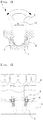
- FIGS. 2 to 4 are views showing a denture-fixing attachment according to one embodiment of the present invention.
- a denture-fixing attachment 1 according to the embodiment is configured to adjust the angle at which a denture 4 is fixed to a fixture 3 implanted into an alveolar bone 2, thereby freely connecting the denture 4 to the fixture 3 implanted in a slanted direction.
- an implant recess used to implant the fixture 3 is formed in the alveolar bone 2 using a tool such as, for example, a drill, the fixture 3 is implanted into the implant recess, and the attachment is fixed to the fixture 3 and serves as a connection component for connecting the denture 4 to the fixture 3.
- the implant recess has female threads formed therein, and the fixture 3 has male threads formed in the outer peripheral surface thereof to mesh with the female threads, so that the fixture 3 is screwed to the implant recess.
- the denture-fixing attachment 1 includes a rod-shaped joint member 5, to an upper end of which the denture 4 is fixed, and an abutment 6 having a coupling portion formed in the outer surface of a lower portion thereof, which is coupled to a fixture recess formed in the fixture 3, and a receiving portion formed in an upper portion thereof, in which a lower portion of the joint member 5 is received.
- the denture-fixing attachment includes the abutment 6, which is coupled to the fixture 3, and the joint member 5, which is pivotably and rotatably jointed to the abutment 6 and is connected with the denture 4, so that the denture 3 is fixed to the alveolar bone 2.
- the aforementioned fixture recess is embodied as a spiral nut recess
- the coupling portion of the abutment 6 is embodied as male threads, which mesh with the fixture recess, so that the abutment 6 is screwed to the fixture 3.
- the receiving portion of the abutment 6 includes a receiving recess 7, into which the lower end 11 of the joint member 5 is inserted, and a stop protruding portion 10, which is provided in the receiving portion above the receiving recess 7 and has a guide groove 9, into which a locking protruding portion 8, protruding outward from the lower end 11 of the joint member 5, is fitted and which guides the coupling movement of the locking protruding portion 8.
- the locking protruding portion 8 of the joint member 5 is inserted into the guide groove 9 in the stop protruding portion 10 and is guided thereby, and the lower end 11 of the joint member 5 is received in the receiving recess 7, so that the lower end 11 of the joint member 5 freely pivots and rotates with respect to the inner peripheral surfaces of the receiving recess 7 and the stop protruding portion 10, thereby adjusting the angle formed by the upper end 12 of the joint member 5 and the abutment 6.
- the denture 4 is capable of being stably connected and fixed to the fixture 3.
- the lower end 11 of the joint member 5 received in the receiving recess 7 is in contact with the stop protruding portion 10 provided above the receiving recess 7 so as to be prevented from being unexpectedly separated from the receiving recess 7, thereby enhancing stability without concern as to the release of the engagement of the denture 4 for a long time period.
- stop protruding portion 10 which functions to prevent the lower end 11 of the joint member 5 from being separated from the receiving recess 7, is integrally formed with the receiving recess 7, not only additional parts but also additional fastening elements are unnecessary, which enhances structural strength and enables stable long-term use.
- At least a predetermined portion of the guide groove 9 is preferably formed to extend in a horizontal direction in the inner peripheral surface of the stop protruding portion 10.
- the locking protruding portion 8 is in contact with the horizontally extending portion of the guide groove 9 and is prevented from being separated from the receiving recess 7.
- the guide groove 9 may be formed to have an "L” shape or, as illustrated in FIG. 6 , to have a “ “ shape in the inner peripheral surface of the stop protruding portion 10, and in this case, the locking protruding portion 8 protrudes from the outer peripheral surface of the lower end of the joint member 5, and is fitted into the guide groove (for example, in a push-turn-push engagement manner).
- the locking protruding portion 8 may be preferably formed to have an annular shape around the outer peripheral surface of the lower end of the joint member 5, so that the locking protruding portion 8 is screwed to the spiral guide groove 9.
- annular-shaped locking protruding portion 8 provided at the lower end 11 of the joint member 5 is moved from the opening of the receiving portion to the receiving recess 7 through the screw-engagement with the spiral guide groove 9, and is prevented from being unexpectedly separated from the receiving recess 7.
- the bottom surface of the receiving recess 7 has a hemispherical shape
- the lower end 11 of the joint member 5 also has a hemispherical shape corresponding to the hemispherical-shaped receiving recess 7 so as to come into close contact with the bottom surface of the receiving recess 7, so that the lower end 11 of the joint member 5 easily pivots and rotates with respect to the bottom surface of the receiving recess 7.
- both the upper end 12 and the lower end 11 of the joint member 5 have curved surfaces, more precisely hemispherical-shaped surfaces, and a connection portion 13 between the upper end 12 and the lower end 11 is formed to have a rod shape, which has a smaller diameter than the diameter of the upper end 12.
- the maximum possible area for close contact between the upper end 12 of the joint member 5 and the denture 4 can be secured.
- connection portion 13 since the angle at which the joint member 5 can pivot with respect to the receiving portion is decided depending on the diameter of the connection portion 13, a user may select a connection portion having a suitable shape, and may use the same.
- connection portion 13 the smaller the diameter H or h of the connection portion 13, the larger the pivot range, and accordingly a user may simply select a joint member having a suitable shape for the dental treatment, and assemble and use the same.
- the fixture 3 is first implanted into the alveolar bone 2 as described above.
- the joint member 5 is fastened to the receiving portion of the abutment 6 in a screw-engagement manner so that the lower end 11 of the joint member 5 is inserted and received in the receiving recess 7, and the attachment 1, formed through the assembly of the abutment 6 and the joint member 5, is fastened to the fixture recess of the fixture 3.
- the treatment can be carried out after the angle of the joint member 5 with respect to the receiving recess 7 is adjusted by pivoting the joint member 5.
- the denture-fixing attachment according to the embodiment has an economic effect due to the simple structure of the abutment to which the joint member is pivotably coupled, highly efficient workability due to a simplified assembly process, and increased stability in long-term use due to structural stability in that the receiving recess and the stop protruding portion, which constitute the receiving portion, are integrally formed.
- the present invention relates to a denture-fixing attachment used to fix a denture after a dental implant treatment and, more particularly, to a denture-fixing attachment, which has an economic effect due to a simple structure and consequent improvement of productivity, highly efficient workability due to a simplified assembly process, and increased stability in use due to the secure maintenance of engagement force for a long time period and the consequent prevention of unexpected release of engagement, and therefore, the present invention has industrial applicability.
Landscapes
- Health & Medical Sciences (AREA)
- Oral & Maxillofacial Surgery (AREA)
- Dentistry (AREA)
- Epidemiology (AREA)
- Life Sciences & Earth Sciences (AREA)
- Animal Behavior & Ethology (AREA)
- General Health & Medical Sciences (AREA)
- Public Health (AREA)
- Veterinary Medicine (AREA)
- Orthopedic Medicine & Surgery (AREA)
- Dental Prosthetics (AREA)
Priority Applications (1)
| Application Number | Priority Date | Filing Date | Title |
|---|---|---|---|
| PL15759038T PL3115019T3 (pl) | 2014-03-06 | 2015-02-02 | Mocowanie łącznika protetycznego |
Applications Claiming Priority (2)
| Application Number | Priority Date | Filing Date | Title |
|---|---|---|---|
| KR1020140026568A KR101407224B1 (ko) | 2014-03-06 | 2014-03-06 | 틀니 고정용 어태치먼트 |
| PCT/KR2015/001053 WO2015133733A1 (ko) | 2014-03-06 | 2015-02-02 | 틀니 고정용 어태치먼트 |
Publications (3)
| Publication Number | Publication Date |
|---|---|
| EP3115019A1 true EP3115019A1 (de) | 2017-01-11 |
| EP3115019A4 EP3115019A4 (de) | 2017-11-08 |
| EP3115019B1 EP3115019B1 (de) | 2020-05-06 |
Family
ID=51132825
Family Applications (1)
| Application Number | Title | Priority Date | Filing Date |
|---|---|---|---|
| EP15759038.1A Active EP3115019B1 (de) | 2014-03-06 | 2015-02-02 | Zahnersatzbefestigung |
Country Status (16)
| Country | Link |
|---|---|
| US (1) | US10213279B2 (de) |
| EP (1) | EP3115019B1 (de) |
| JP (1) | JP6197191B2 (de) |
| KR (1) | KR101407224B1 (de) |
| CN (1) | CN106061430B (de) |
| BR (1) | BR112016020657B1 (de) |
| DK (1) | DK3115019T3 (de) |
| ES (1) | ES2803575T3 (de) |
| HK (1) | HK1225264B (de) |
| HU (1) | HUE051142T2 (de) |
| PL (1) | PL3115019T3 (de) |
| PT (1) | PT3115019T (de) |
| RU (1) | RU2658158C2 (de) |
| SA (1) | SA516371775B1 (de) |
| TW (1) | TWI568420B (de) |
| WO (1) | WO2015133733A1 (de) |
Families Citing this family (10)
| Publication number | Priority date | Publication date | Assignee | Title |
|---|---|---|---|---|
| RU186944U1 (ru) * | 2018-11-06 | 2019-02-11 | ООО "Энергосбережение" | Устройство обработки жидкого углеводородного топлива под воздействием электрического поля перед процессом сжигания в различных энергетических установках |
| KR20200130080A (ko) * | 2019-05-09 | 2020-11-18 | 주식회사 덴플렉스 | 덴쳐용 어태치먼트 |
| CN110478066B (zh) * | 2019-08-27 | 2024-01-30 | 江苏省人民医院(南京医科大学第一附属医院) | 用于口腔种植修复前压低伸长的对颌牙齿的基台矫正附件 |
| RU196535U1 (ru) * | 2019-09-05 | 2020-03-04 | Михаил Анатольевич Крючков | Телескопический фиксатор-абатмент для вторичной конструкции из полиэфирэфиркетона |
| WO2021173628A1 (en) | 2020-02-27 | 2021-09-02 | New Way Denture & Retention Systems, LLC | Denture retention apparatus and method |
| TWI712397B (zh) * | 2020-03-18 | 2020-12-11 | 吳冠霖 | 可調整角度之支台齒結構 |
| CN113229967B (zh) * | 2021-05-10 | 2022-06-21 | 西安交通大学口腔医院 | 一种口腔种植导板固定装置 |
| US12303352B2 (en) | 2021-06-03 | 2025-05-20 | Full Arch Solutions, Llc | Omni-directional multi-unit abutment dental systems |
| IL309005B2 (en) | 2021-06-03 | 2025-07-01 | Full Arch Solutions Llc | Multi-unit omnidirectional support system for dental screw-attached dentures |
| CN114041893B (zh) * | 2021-11-02 | 2024-10-01 | 广州医科大学附属口腔医院(广州医科大学羊城医院) | 种植体支持的咬合定位器 |
Family Cites Families (27)
| Publication number | Priority date | Publication date | Assignee | Title |
|---|---|---|---|---|
| US866304A (en) * | 1904-04-18 | 1907-09-17 | Finis E Roach | Removable artificial denture. |
| US4540367A (en) * | 1984-05-02 | 1985-09-10 | Sulc Josef M | Dental attachment structure |
| DE3531389A1 (de) | 1985-09-03 | 1987-03-05 | Kirsch Axel | Enossales implantat |
| US4832601A (en) * | 1987-12-04 | 1989-05-23 | Hall Surgical | Adjustable support for a prosthetic tooth and method |
| BE1002350A3 (fr) * | 1988-08-02 | 1991-01-08 | Dury Georges Emile Ladislas | Implant. |
| AT393952B (de) * | 1990-08-01 | 1992-01-10 | Sichler Heimo | Thermisch verstell- und fixierbarer implantatpfosten |
| US5302125A (en) * | 1992-10-22 | 1994-04-12 | Kownacki Charles D | Dental prosthetic implant |
| US5453007A (en) * | 1993-04-08 | 1995-09-26 | Wagher; Felix | Elastic dental implant |
| IT233018Y1 (it) * | 1993-09-22 | 2000-01-26 | Rhein 83 S N C Di Nardi Ezio & | Dispositivo per realizzare attacchi rapidi per protesi dentarie |
| US5417570A (en) * | 1994-01-03 | 1995-05-23 | Zest Anchors, Inc. | Dental anchor assembly |
| KR19990082264A (ko) * | 1996-02-02 | 1999-11-25 | 키이스 디 | 치료 접합부와 의치본 코핑이 조합된 융기 프로파일 시스템 |
| US5890902A (en) * | 1997-09-19 | 1999-04-06 | Sapian; Schubert L. | Implant bone locking mechanism and artificial periodontal ligament system |
| JP3652873B2 (ja) | 1998-02-27 | 2005-05-25 | 京セラ株式会社 | 歯科磁性部材用ホルダー |
| US6102702A (en) | 1998-12-28 | 2000-08-15 | Aubrey Clinton Folsom, Jr. | Quick tightening abutment lock |
| CN2484915Y (zh) * | 2001-06-28 | 2002-04-10 | 王宝锷 | 口腔种植用基台 |
| US6843653B2 (en) * | 2002-06-04 | 2005-01-18 | Joseph Carlton | Dental implant |
| US7217130B2 (en) | 2002-06-07 | 2007-05-15 | Thierry Giorno | Prosthesis mounting device and assembly |
| KR20070112075A (ko) | 2006-05-19 | 2007-11-22 | 오성균 | 치과 임플란트의 분리형 어버트먼트 및 이를 이용한 치과보철물의 제조방법 |
| IL181989A (en) * | 2007-03-18 | 2011-11-30 | Ophir Fromovich | Angular spherical connector |
| NL2002019C (nl) * | 2008-09-25 | 2010-03-29 | Biocomp Ind B V | Implantaatconstructie. |
| US7959439B2 (en) * | 2008-10-23 | 2011-06-14 | Intrinsic Medical, Llc | Apparatus, system, and method for implanting dental prosthesis |
| KR101042372B1 (ko) | 2009-04-09 | 2011-06-17 | 오스템임플란트 주식회사 | 일체형 임플란트 |
| ES2380036B1 (es) * | 2009-10-08 | 2013-03-15 | Ramon Farre Berga | Pilar de retencion de protesis dentales |
| RU94842U1 (ru) * | 2009-12-03 | 2010-06-10 | Владимир Алексеевич Васильев | Дентальный имплантат (варианты) |
| WO2012142517A2 (en) * | 2011-04-15 | 2012-10-18 | Jbsg Management Llc | Polyaxial dental implant system |
| KR200471489Y1 (ko) | 2012-04-04 | 2014-02-28 | 왕제원 | 각도조절과 위치조절이 자유로운 틀니 고정용 어태치먼트 |
| ITVI20130070A1 (it) * | 2013-03-14 | 2013-06-13 | Giandomenico Gonella | Dispositivo per uso odontotecnico. |
-
2014
- 2014-03-06 KR KR1020140026568A patent/KR101407224B1/ko active Active
-
2015
- 2015-02-02 HU HUE15759038A patent/HUE051142T2/hu unknown
- 2015-02-02 PT PT157590381T patent/PT3115019T/pt unknown
- 2015-02-02 HK HK16113828.3A patent/HK1225264B/zh unknown
- 2015-02-02 BR BR112016020657-6A patent/BR112016020657B1/pt active IP Right Grant
- 2015-02-02 RU RU2016135511A patent/RU2658158C2/ru active
- 2015-02-02 WO PCT/KR2015/001053 patent/WO2015133733A1/ko not_active Ceased
- 2015-02-02 PL PL15759038T patent/PL3115019T3/pl unknown
- 2015-02-02 JP JP2016570747A patent/JP6197191B2/ja active Active
- 2015-02-02 US US15/120,938 patent/US10213279B2/en active Active
- 2015-02-02 ES ES15759038T patent/ES2803575T3/es active Active
- 2015-02-02 EP EP15759038.1A patent/EP3115019B1/de active Active
- 2015-02-02 DK DK15759038.1T patent/DK3115019T3/da active
- 2015-02-02 CN CN201580011530.9A patent/CN106061430B/zh active Active
- 2015-03-04 TW TW104106809A patent/TWI568420B/zh active
-
2016
- 2016-08-31 SA SA516371775A patent/SA516371775B1/ar unknown
Also Published As
| Publication number | Publication date |
|---|---|
| SA516371775B1 (ar) | 2019-09-25 |
| KR101407224B1 (ko) | 2014-06-17 |
| JP6197191B2 (ja) | 2017-09-20 |
| WO2015133733A1 (ko) | 2015-09-11 |
| ES2803575T3 (es) | 2021-01-28 |
| RU2016135511A (ru) | 2018-03-02 |
| US20160361144A1 (en) | 2016-12-15 |
| US10213279B2 (en) | 2019-02-26 |
| EP3115019A4 (de) | 2017-11-08 |
| DK3115019T3 (da) | 2020-08-03 |
| PT3115019T (pt) | 2020-07-28 |
| EP3115019B1 (de) | 2020-05-06 |
| TW201534279A (zh) | 2015-09-16 |
| CN106061430A (zh) | 2016-10-26 |
| PL3115019T3 (pl) | 2020-11-16 |
| HUE051142T2 (hu) | 2021-03-01 |
| BR112016020657B1 (pt) | 2021-01-26 |
| RU2016135511A3 (de) | 2018-03-02 |
| HK1225264B (zh) | 2017-09-08 |
| CN106061430B (zh) | 2018-04-17 |
| JP2017506137A (ja) | 2017-03-02 |
| TWI568420B (zh) | 2017-02-01 |
| RU2658158C2 (ru) | 2018-06-19 |
Similar Documents
| Publication | Publication Date | Title |
|---|---|---|
| EP3115019B1 (de) | Zahnersatzbefestigung | |
| US11213372B2 (en) | Screwless dental implant connection | |
| US20090298013A1 (en) | Inclined dental abutment assembly device | |
| IL268492A (en) | Fixation unit for a dental device | |
| EP2835110B1 (de) | Zahnersatzbefestigung mit frei einstellbarem winkel und frei einstellbarer position | |
| JP2021505257A (ja) | 歯科用インプラントのフィクスチャー | |
| KR101524192B1 (ko) | 치과용 임플란트의 치경부 형상 지대주 | |
| KR101106161B1 (ko) | 어버트먼트와 지르코니아 캡의 견고한 체결구조를 갖는 임플란트장치 | |
| KR101486851B1 (ko) | 치과용 임플란트의 지대주 | |
| US20140272788A1 (en) | Twist lock interface for abutment and implant assembly | |
| EP3372190B1 (de) | Einheit mit einem dentalimplantat und prothetischen komponenten, einschliesslich einer transepithelialen hülse mit einer verdrehsichere oberen verbindung |
Legal Events
| Date | Code | Title | Description |
|---|---|---|---|
| STAA | Information on the status of an ep patent application or granted ep patent |
Free format text: STATUS: THE INTERNATIONAL PUBLICATION HAS BEEN MADE |
|
| PUAI | Public reference made under article 153(3) epc to a published international application that has entered the european phase |
Free format text: ORIGINAL CODE: 0009012 |
|
| STAA | Information on the status of an ep patent application or granted ep patent |
Free format text: STATUS: REQUEST FOR EXAMINATION WAS MADE |
|
| 17P | Request for examination filed |
Effective date: 20160902 |
|
| AK | Designated contracting states |
Kind code of ref document: A1 Designated state(s): AL AT BE BG CH CY CZ DE DK EE ES FI FR GB GR HR HU IE IS IT LI LT LU LV MC MK MT NL NO PL PT RO RS SE SI SK SM TR |
|
| AX | Request for extension of the european patent |
Extension state: BA ME |
|
| DAX | Request for extension of the european patent (deleted) | ||
| A4 | Supplementary search report drawn up and despatched |
Effective date: 20171011 |
|
| RIC1 | Information provided on ipc code assigned before grant |
Ipc: A61C 13/267 20060101ALI20171005BHEP Ipc: A61C 8/00 20060101ALI20171005BHEP Ipc: A61C 13/263 20060101AFI20171005BHEP |
|
| GRAP | Despatch of communication of intention to grant a patent |
Free format text: ORIGINAL CODE: EPIDOSNIGR1 |
|
| STAA | Information on the status of an ep patent application or granted ep patent |
Free format text: STATUS: GRANT OF PATENT IS INTENDED |
|
| INTG | Intention to grant announced |
Effective date: 20191119 |
|
| GRAS | Grant fee paid |
Free format text: ORIGINAL CODE: EPIDOSNIGR3 |
|
| GRAA | (expected) grant |
Free format text: ORIGINAL CODE: 0009210 |
|
| STAA | Information on the status of an ep patent application or granted ep patent |
Free format text: STATUS: THE PATENT HAS BEEN GRANTED |
|
| AK | Designated contracting states |
Kind code of ref document: B1 Designated state(s): AL AT BE BG CH CY CZ DE DK EE ES FI FR GB GR HR HU IE IS IT LI LT LU LV MC MK MT NL NO PL PT RO RS SE SI SK SM TR |
|
| REG | Reference to a national code |
Ref country code: GB Ref legal event code: FG4D |
|
| REG | Reference to a national code |
Ref country code: AT Ref legal event code: REF Ref document number: 1265561 Country of ref document: AT Kind code of ref document: T Effective date: 20200515 Ref country code: CH Ref legal event code: EP |
|
| REG | Reference to a national code |
Ref country code: IE Ref legal event code: FG4D |
|
| REG | Reference to a national code |
Ref country code: DE Ref legal event code: R096 Ref document number: 602015052251 Country of ref document: DE |
|
| REG | Reference to a national code |
Ref country code: PT Ref legal event code: SC4A Ref document number: 3115019 Country of ref document: PT Date of ref document: 20200728 Kind code of ref document: T Free format text: AVAILABILITY OF NATIONAL TRANSLATION Effective date: 20200722 |
|
| REG | Reference to a national code |
Ref country code: CH Ref legal event code: NV Representative=s name: MICHELI AND CIE SA, CH |
|
| REG | Reference to a national code |
Ref country code: DK Ref legal event code: T3 Effective date: 20200728 |
|
| REG | Reference to a national code |
Ref country code: NL Ref legal event code: FP |
|
| REG | Reference to a national code |
Ref country code: SE Ref legal event code: TRGR |
|
| REG | Reference to a national code |
Ref country code: LT Ref legal event code: MG4D |
|
| PG25 | Lapsed in a contracting state [announced via postgrant information from national office to epo] |
Ref country code: IS Free format text: LAPSE BECAUSE OF FAILURE TO SUBMIT A TRANSLATION OF THE DESCRIPTION OR TO PAY THE FEE WITHIN THE PRESCRIBED TIME-LIMIT Effective date: 20200906 Ref country code: NO Free format text: LAPSE BECAUSE OF FAILURE TO SUBMIT A TRANSLATION OF THE DESCRIPTION OR TO PAY THE FEE WITHIN THE PRESCRIBED TIME-LIMIT Effective date: 20200806 Ref country code: GR Free format text: LAPSE BECAUSE OF FAILURE TO SUBMIT A TRANSLATION OF THE DESCRIPTION OR TO PAY THE FEE WITHIN THE PRESCRIBED TIME-LIMIT Effective date: 20200807 Ref country code: FI Free format text: LAPSE BECAUSE OF FAILURE TO SUBMIT A TRANSLATION OF THE DESCRIPTION OR TO PAY THE FEE WITHIN THE PRESCRIBED TIME-LIMIT Effective date: 20200506 Ref country code: LT Free format text: LAPSE BECAUSE OF FAILURE TO SUBMIT A TRANSLATION OF THE DESCRIPTION OR TO PAY THE FEE WITHIN THE PRESCRIBED TIME-LIMIT Effective date: 20200506 |
|
| PG25 | Lapsed in a contracting state [announced via postgrant information from national office to epo] |
Ref country code: LV Free format text: LAPSE BECAUSE OF FAILURE TO SUBMIT A TRANSLATION OF THE DESCRIPTION OR TO PAY THE FEE WITHIN THE PRESCRIBED TIME-LIMIT Effective date: 20200506 Ref country code: HR Free format text: LAPSE BECAUSE OF FAILURE TO SUBMIT A TRANSLATION OF THE DESCRIPTION OR TO PAY THE FEE WITHIN THE PRESCRIBED TIME-LIMIT Effective date: 20200506 Ref country code: RS Free format text: LAPSE BECAUSE OF FAILURE TO SUBMIT A TRANSLATION OF THE DESCRIPTION OR TO PAY THE FEE WITHIN THE PRESCRIBED TIME-LIMIT Effective date: 20200506 Ref country code: BG Free format text: LAPSE BECAUSE OF FAILURE TO SUBMIT A TRANSLATION OF THE DESCRIPTION OR TO PAY THE FEE WITHIN THE PRESCRIBED TIME-LIMIT Effective date: 20200806 |
|
| PG25 | Lapsed in a contracting state [announced via postgrant information from national office to epo] |
Ref country code: AL Free format text: LAPSE BECAUSE OF FAILURE TO SUBMIT A TRANSLATION OF THE DESCRIPTION OR TO PAY THE FEE WITHIN THE PRESCRIBED TIME-LIMIT Effective date: 20200506 |
|
| REG | Reference to a national code |
Ref country code: ES Ref legal event code: FG2A Ref document number: 2803575 Country of ref document: ES Kind code of ref document: T3 Effective date: 20210128 |
|
| PG25 | Lapsed in a contracting state [announced via postgrant information from national office to epo] |
Ref country code: RO Free format text: LAPSE BECAUSE OF FAILURE TO SUBMIT A TRANSLATION OF THE DESCRIPTION OR TO PAY THE FEE WITHIN THE PRESCRIBED TIME-LIMIT Effective date: 20200506 Ref country code: SM Free format text: LAPSE BECAUSE OF FAILURE TO SUBMIT A TRANSLATION OF THE DESCRIPTION OR TO PAY THE FEE WITHIN THE PRESCRIBED TIME-LIMIT Effective date: 20200506 Ref country code: EE Free format text: LAPSE BECAUSE OF FAILURE TO SUBMIT A TRANSLATION OF THE DESCRIPTION OR TO PAY THE FEE WITHIN THE PRESCRIBED TIME-LIMIT Effective date: 20200506 |
|
| REG | Reference to a national code |
Ref country code: DE Ref legal event code: R097 Ref document number: 602015052251 Country of ref document: DE |
|
| PG25 | Lapsed in a contracting state [announced via postgrant information from national office to epo] |
Ref country code: SK Free format text: LAPSE BECAUSE OF FAILURE TO SUBMIT A TRANSLATION OF THE DESCRIPTION OR TO PAY THE FEE WITHIN THE PRESCRIBED TIME-LIMIT Effective date: 20200506 |
|
| REG | Reference to a national code |
Ref country code: HU Ref legal event code: AG4A Ref document number: E051142 Country of ref document: HU |
|
| PLBE | No opposition filed within time limit |
Free format text: ORIGINAL CODE: 0009261 |
|
| STAA | Information on the status of an ep patent application or granted ep patent |
Free format text: STATUS: NO OPPOSITION FILED WITHIN TIME LIMIT |
|
| 26N | No opposition filed |
Effective date: 20210209 |
|
| REG | Reference to a national code |
Ref country code: AT Ref legal event code: UEP Ref document number: 1265561 Country of ref document: AT Kind code of ref document: T Effective date: 20200506 |
|
| PG25 | Lapsed in a contracting state [announced via postgrant information from national office to epo] |
Ref country code: SI Free format text: LAPSE BECAUSE OF FAILURE TO SUBMIT A TRANSLATION OF THE DESCRIPTION OR TO PAY THE FEE WITHIN THE PRESCRIBED TIME-LIMIT Effective date: 20200506 |
|
| PG25 | Lapsed in a contracting state [announced via postgrant information from national office to epo] |
Ref country code: MC Free format text: LAPSE BECAUSE OF FAILURE TO SUBMIT A TRANSLATION OF THE DESCRIPTION OR TO PAY THE FEE WITHIN THE PRESCRIBED TIME-LIMIT Effective date: 20200506 |
|
| REG | Reference to a national code |
Ref country code: BE Ref legal event code: MM Effective date: 20210228 |
|
| PG25 | Lapsed in a contracting state [announced via postgrant information from national office to epo] |
Ref country code: LU Free format text: LAPSE BECAUSE OF NON-PAYMENT OF DUE FEES Effective date: 20210202 |
|
| PG25 | Lapsed in a contracting state [announced via postgrant information from national office to epo] |
Ref country code: IE Free format text: LAPSE BECAUSE OF NON-PAYMENT OF DUE FEES Effective date: 20210202 |
|
| PG25 | Lapsed in a contracting state [announced via postgrant information from national office to epo] |
Ref country code: BE Free format text: LAPSE BECAUSE OF NON-PAYMENT OF DUE FEES Effective date: 20210228 |
|
| PG25 | Lapsed in a contracting state [announced via postgrant information from national office to epo] |
Ref country code: CY Free format text: LAPSE BECAUSE OF FAILURE TO SUBMIT A TRANSLATION OF THE DESCRIPTION OR TO PAY THE FEE WITHIN THE PRESCRIBED TIME-LIMIT Effective date: 20200506 |
|
| PG25 | Lapsed in a contracting state [announced via postgrant information from national office to epo] |
Ref country code: MK Free format text: LAPSE BECAUSE OF FAILURE TO SUBMIT A TRANSLATION OF THE DESCRIPTION OR TO PAY THE FEE WITHIN THE PRESCRIBED TIME-LIMIT Effective date: 20200506 |
|
| PG25 | Lapsed in a contracting state [announced via postgrant information from national office to epo] |
Ref country code: MT Free format text: LAPSE BECAUSE OF FAILURE TO SUBMIT A TRANSLATION OF THE DESCRIPTION OR TO PAY THE FEE WITHIN THE PRESCRIBED TIME-LIMIT Effective date: 20200506 |
|
| PGFP | Annual fee paid to national office [announced via postgrant information from national office to epo] |
Ref country code: NL Payment date: 20250121 Year of fee payment: 11 |
|
| PGFP | Annual fee paid to national office [announced via postgrant information from national office to epo] |
Ref country code: HU Payment date: 20250220 Year of fee payment: 11 |
|
| PGFP | Annual fee paid to national office [announced via postgrant information from national office to epo] |
Ref country code: DE Payment date: 20250120 Year of fee payment: 11 Ref country code: PT Payment date: 20250121 Year of fee payment: 11 |
|
| PGFP | Annual fee paid to national office [announced via postgrant information from national office to epo] |
Ref country code: DK Payment date: 20250122 Year of fee payment: 11 |
|
| PGFP | Annual fee paid to national office [announced via postgrant information from national office to epo] |
Ref country code: ES Payment date: 20250314 Year of fee payment: 11 |
|
| PGFP | Annual fee paid to national office [announced via postgrant information from national office to epo] |
Ref country code: SE Payment date: 20250121 Year of fee payment: 11 |
|
| PGFP | Annual fee paid to national office [announced via postgrant information from national office to epo] |
Ref country code: CH Payment date: 20250301 Year of fee payment: 11 Ref country code: AT Payment date: 20250120 Year of fee payment: 11 |
|
| PGFP | Annual fee paid to national office [announced via postgrant information from national office to epo] |
Ref country code: CZ Payment date: 20250122 Year of fee payment: 11 Ref country code: PL Payment date: 20250122 Year of fee payment: 11 Ref country code: FR Payment date: 20250122 Year of fee payment: 11 |
|
| PGFP | Annual fee paid to national office [announced via postgrant information from national office to epo] |
Ref country code: IT Payment date: 20250121 Year of fee payment: 11 Ref country code: GB Payment date: 20250120 Year of fee payment: 11 |
|
| PGFP | Annual fee paid to national office [announced via postgrant information from national office to epo] |
Ref country code: TR Payment date: 20250121 Year of fee payment: 11 |