EP3114643B1 - Tiefenbewusste verstärkung für stereovideo - Google Patents
Tiefenbewusste verstärkung für stereovideo Download PDFInfo
- Publication number
- EP3114643B1 EP3114643B1 EP15708645.5A EP15708645A EP3114643B1 EP 3114643 B1 EP3114643 B1 EP 3114643B1 EP 15708645 A EP15708645 A EP 15708645A EP 3114643 B1 EP3114643 B1 EP 3114643B1
- Authority
- EP
- European Patent Office
- Prior art keywords
- image
- depth
- determining
- block
- right image
- Prior art date
- Legal status (The legal status is an assumption and is not a legal conclusion. Google has not performed a legal analysis and makes no representation as to the accuracy of the status listed.)
- Active
Links
Images


Classifications
-
- G—PHYSICS
- G06—COMPUTING OR CALCULATING; COUNTING
- G06T—IMAGE DATA PROCESSING OR GENERATION, IN GENERAL
- G06T5/00—Image enhancement or restoration
- G06T5/50—Image enhancement or restoration using two or more images, e.g. averaging or subtraction
-
- H—ELECTRICITY
- H04—ELECTRIC COMMUNICATION TECHNIQUE
- H04N—PICTORIAL COMMUNICATION, e.g. TELEVISION
- H04N13/00—Stereoscopic video systems; Multi-view video systems; Details thereof
- H04N13/10—Processing, recording or transmission of stereoscopic or multi-view image signals
- H04N13/106—Processing image signals
-
- G—PHYSICS
- G06—COMPUTING OR CALCULATING; COUNTING
- G06T—IMAGE DATA PROCESSING OR GENERATION, IN GENERAL
- G06T2207/00—Indexing scheme for image analysis or image enhancement
- G06T2207/10—Image acquisition modality
- G06T2207/10004—Still image; Photographic image
- G06T2207/10012—Stereo images
-
- G—PHYSICS
- G06—COMPUTING OR CALCULATING; COUNTING
- G06T—IMAGE DATA PROCESSING OR GENERATION, IN GENERAL
- G06T2207/00—Indexing scheme for image analysis or image enhancement
- G06T2207/10—Image acquisition modality
- G06T2207/10024—Color image
-
- G—PHYSICS
- G06—COMPUTING OR CALCULATING; COUNTING
- G06T—IMAGE DATA PROCESSING OR GENERATION, IN GENERAL
- G06T2207/00—Indexing scheme for image analysis or image enhancement
- G06T2207/10—Image acquisition modality
- G06T2207/10028—Range image; Depth image; 3D point clouds
-
- G—PHYSICS
- G06—COMPUTING OR CALCULATING; COUNTING
- G06T—IMAGE DATA PROCESSING OR GENERATION, IN GENERAL
- G06T2207/00—Indexing scheme for image analysis or image enhancement
- G06T2207/20—Special algorithmic details
- G06T2207/20004—Adaptive image processing
- G06T2207/20012—Locally adaptive
-
- G—PHYSICS
- G06—COMPUTING OR CALCULATING; COUNTING
- G06T—IMAGE DATA PROCESSING OR GENERATION, IN GENERAL
- G06T2207/00—Indexing scheme for image analysis or image enhancement
- G06T2207/20—Special algorithmic details
- G06T2207/20092—Interactive image processing based on input by user
- G06T2207/20104—Interactive definition of region of interest [ROI]
-
- G—PHYSICS
- G06—COMPUTING OR CALCULATING; COUNTING
- G06T—IMAGE DATA PROCESSING OR GENERATION, IN GENERAL
- G06T2207/00—Indexing scheme for image analysis or image enhancement
- G06T2207/20—Special algorithmic details
- G06T2207/20172—Image enhancement details
- G06T2207/20192—Edge enhancement; Edge preservation
-
- H—ELECTRICITY
- H04—ELECTRIC COMMUNICATION TECHNIQUE
- H04N—PICTORIAL COMMUNICATION, e.g. TELEVISION
- H04N13/00—Stereoscopic video systems; Multi-view video systems; Details thereof
- H04N2013/0074—Stereoscopic image analysis
- H04N2013/0081—Depth or disparity estimation from stereoscopic image signals
-
- H—ELECTRICITY
- H04—ELECTRIC COMMUNICATION TECHNIQUE
- H04N—PICTORIAL COMMUNICATION, e.g. TELEVISION
- H04N13/00—Stereoscopic video systems; Multi-view video systems; Details thereof
- H04N2013/0074—Stereoscopic image analysis
- H04N2013/0088—Synthesising a monoscopic image signal from stereoscopic images, e.g. synthesising a panoramic or high resolution monoscopic image
-
- H—ELECTRICITY
- H04—ELECTRIC COMMUNICATION TECHNIQUE
- H04N—PICTORIAL COMMUNICATION, e.g. TELEVISION
- H04N13/00—Stereoscopic video systems; Multi-view video systems; Details thereof
- H04N2013/0074—Stereoscopic image analysis
- H04N2013/0092—Image segmentation from stereoscopic image signals
Definitions
- This disclosure is related to the field of depth-based image enhancement. More particularly, this disclosure relates to the enhancement of monocular images using depth computed from stereo images.
- Visual media such as images and video
- the captured media can be captured with a camera or video camera.
- the camera or video camera includes sufficient features and includes a proper lens, the captured media reflects the color, contrast, sharpness, and/or the like desired by the end-user.
- full-featured cameras or video cameras and/or powerful lenses can be expensive.
- full-featured cameras or videos cameras and/or powerful lenses can be bulky and difficult to carry in certain situations.
- portable devices such as cell phones or tablets, include a built-in camera.
- portable devices include a wide array of functions in addition to the ability to capture visual media, many people forgo carrying the bulky, expensive cameras and lenses in favor of the portable devices.
- the cameras built into the portable devices have a restricted number of features.
- the built-in cameras generally have basic lenses.
- the visual media captured by the built-in cameras are generally of a poorer quality and lack the desired color, contrast, sharpness, and/or the like.
- Applications available on the portable device or another device can be used to process and enhance the captured visual media.
- applications can be used by the end-user to adjust color, enhance contrast, sharpen edges, and/or the like.
- many of the applications can be processor-intensive and/or require additional hardware. This can be especially problematic on portable devices, as the applications can increase battery consumption and/or the size of the device.
- a layer generator divides the 3D image into a series of depth steps and generates a layer that contains the objects in each depth step.
- the layer generator uses object distances generated by the distance calculator to determine the contents of each depth step.
- the blur factor calculator and blur filter operate in conjunction to apply an image blur to each layer.
- the layer generator also identifies the layer corresponding to the subject as the subject layer, and the blur factor calculator and blur filter may be configured so that they do not apply image blur to the subject layer.
- full-featured cameras or video cameras that have powerful lenses and/or other components can be expensive.
- Applications available on a device can be used to process and enhance captured visual media (e.g., images, video, etc.) to mimic the effects produced by the powerful lenses and/or other components.
- applications can be used by an end-user to adjust color, enhance contrast, sharpen edges, change geometric shapes, and/or the like.
- many of the applications are processor-intensive and/or require additional hardware to implement some or all of the enhancement features.
- the process or determining a portion of the media to enhance can be processor-intensive.
- Stereo images generally include a first image and a second image of a common scene.
- the first and second images may throughout this disclosure also be referred to as left and right images, left and right views, or left (L) and right (R) frames.
- the first and second images of the stereo pair can be displayed simultaneously or in rapid succession to create a scene with 3D objects.
- Stereo images or video can be captured using two cameras and are transmitted as a stream of left frames and right frames.
- a depth map can be formed based on the disparity map.
- the disparity map can be scaled such that the disparity values range from 0 to a set number (e.g., 255).
- the scaled disparity map is referred to herein as a depth map.
- the scaled values in the depth map correspond with a grayscale (e.g., an 8-bit grayscale if the set number is 255).
- the depth map can be graphically represented via a grayscale image.
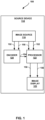
- FIG. 1 is a block diagram illustrating an example system in which a source device enhances a stereo image.
- system 100 may include a source device 112 with image source 116, encoder 120, processor 122, and image display 123.
- Source device 112 may comprise a wireless communication device, such as a wireless handset, a so-called cellular or satellite radiotelephone, or any wireless device that can communicate picture and/or video information over a communication channel, in which case the communication channel may comprise a wireless communication channel.
- Image source 116 may comprise an image sensor array (e.g., a digital still picture camera or digital video camera), a computer-readable storage medium comprising one or more stored images, an interface for receiving digital images from an external source, a processing unit that generates digital images such as by executing a video game or other interactive multimedia source, or other sources of image data.
- Image source 22 may generally correspond to a source of any one or more of captured, pre-captured, and/or computer-generated images.
- image source 116 may correspond to a camera of a cellular (i.e., mobile) telephone.
- references to images in this disclosure include both still pictures as well as frames of video data.
- aspects of this disclosure may apply both to still digital pictures as well as frames of captured digital video data or computer-generated digital video data.
- image source 116 may capture two views of a scene at different perspectives.
- image source 116 may comprise a standard two-dimensional camera, a two camera system that provides a stereoscopic view of a scene, a camera array that captures multiple views of the scene, a camera that captures one view plus depth information, or a first camera on a first device and a second camera on a second device that together provide a stereoscopic view of the scene.
- Encoder 120 uses first view 150 and second view 152 to generate a depth map 154. Encoder 120 transfers the depth map 154 to processor 122. Processor 122 uses first view 150, second view 152, and the depth map 154 to generate enhanced first view 156, which is an enhanced version of first view 150, and/or to generate enhanced second view 158, which is an enhanced version of second view 152. Processor 122 transmits enhanced first view 156 and/or enhanced second view 158 to image display 123.
- image display 123 can render an enhanced two-dimensional or three-dimensional image.
- image display 123 can synthesize enhanced first view 156 and enhanced second view 158 to form and display a single two-dimensional image.
- image display 123 can simultaneously or alternately display two-dimensional versions of enhanced first view 156 and enhanced second view 158 (e.g., to create a three-dimensional effect).
- image display 123 can synthesize enhanced first view 156 and enhanced second view 158 to form and display a single three-dimensional image.
- the human vision system perceives depth based on an angle of convergence to an object. Objects relatively nearer to the viewer are perceived as closer to the viewer due to the viewer's eyes converging on the object at a greater angle than objects that are relatively further from the viewer.
- image display 123 can display two images to a viewer, one image (left and right) for each of the viewer's eyes. Objects that are located at the same spatial location within the image will be generally perceived as being at the same depth as the screen on which the images are being displayed.
- encoder 120 may be configured to encode the enhanced first view 156 and/or enhanced second view 158 as, for example, a Joint Photographic Experts Group (JPEG) image.
- JPEG Joint Photographic Experts Group
- encoder 120 may be configured to encode enhanced first view 156 and/or enhanced second view 158 according to a video coding standard such as, for example Motion Picture Experts Group (MPEG), MPEG-2, International Telecommunication Union (ITU) H.261, ISO/IEC MPEG-1 Visual, ITU-T H.262 or ISO/IEC MPEG-2 Visual, ITU H.263, ISO/IEC MPEG-4 Visual and ITU-T H.264 (also known as ISO/IEC MPEG-4 Advanced Video Coding (AVC)), including its SVC and Multiview Video Coding (MVC) extensions, ITU-T H.265, or other video encoding standards.
- MPEG Motion Picture Experts Group
- ISO International Telecommunication Union
- ISO/IEC MPEG-1 Visual ISO/IEC MPEG-1 Visual
- the ITU-T H.264/MPEG-4 (AVC) standard was formulated by the ITU-T Video Coding Experts Group (VCEG) together with the ISO/IEC Moving Picture Experts Group (MPEG) as the product of a collective partnership known as the Joint Video Team (JVT).
- JVT Joint Video Team
- the techniques described in this disclosure may be applied to devices that generally conform to the H.264 standard.
- the H.264 standard is described in ITU-T Recommendation H.264, Advanced Video Coding for generic audiovisual services, by the ITU-T Study Group, and dated March, 2005, which may be referred to herein as the H.264 standard or H.264 specification, or the H.264/AVC standard or specification.
- JVT Joint Video Team
- JCT-VC Joint Collaboration Team on Video Coding
- VCEG ITU-T Video Coding Experts Group
- MPEG ISO/IEC Motion Picture Experts Group
- HEVC Working Draft 7 A draft of the HEVC standard, referred to as “HEVC Working Draft 7” is in document HCTVC-I1003, Bross et al., " High Efficiency Video Coding (HEVC) Text Specification Draft 7," Joint Collaborative Team on Video Coding (JCT-VC) of ITU-T SG16 WP3 and ISO/IEC JTC1/SC29/WG11, 9th Meeting: Geneva, Switzerland, April 27, 2012 to May 7, 2012 .
- HEVC High Efficiency Video Coding
- encoder 120 may encode enhanced first view 156 and/or enhanced second view 158 in an intra-prediction mode or an inter-prediction mode.
- the ITU-T H.264 standard supports intra-prediction in various block sizes, such as 16x16, 8x8, or 4x4 for luma components, and 8x8 for chroma components, as well as inter-prediction in various block sizes, such as 16x16, 16x8, 8x16, 8x8, 8x4, 4x8 and 4x4 for luma components and corresponding scaled sizes for chroma components.
- NxN and N by N may be used interchangeably to refer to the pixel dimensions of the block in terms of vertical and horizontal dimensions (e.g., 16x16 pixels or 16 by 16 pixels).
- a 16x16 block will have 16 pixels in a vertical direction and 16 pixels in a horizontal direction.
- an NxN block generally has N pixels in a vertical direction and N pixels in a horizontal direction, where N represents a positive integer value that may be greater than 16.
- the pixels in a block may be arranged in rows and columns.
- Blocks may also be NxM, where N and M are integers that are not necessarily equal.
- Video blocks may comprise blocks of pixel data in the pixel domain, or blocks of transform coefficients in the transform domain (e.g., following application of a transform such as a discrete cosine transform (DCT), an integer transform, a wavelet transform, or a conceptually similar transform to the residual video block data representing pixel differences between coded video blocks and predictive video blocks).
- a transform such as a discrete cosine transform (DCT), an integer transform, a wavelet transform, or a conceptually similar transform to the residual video block data representing pixel differences between coded video blocks and predictive video blocks.
- a video block may comprise blocks of quantized transform coefficients in the transform domain.
- the storage media may be physically transported to the location of destination device 214 and read by an appropriate interface unit for retrieving the data.
- the bitstream including encoded image data 262 may be modulated by a modulator/demodulator (MODEM) before being transmitted by output interface 224.
- MODEM modulator/demodulator
- image source 116 may provide multiple views (i.e. enhanced first view 156 and enhanced second view 158), source device 112 may transmit only the enhanced first view 156 or the enhanced second view 158.
- image source 116 may comprise an eight camera array, intended to produce four pairs of views of a scene to be viewed from different angles.
- Source device 112 may transmit only one image of each pair to destination device 214.
- source device 112 may transmit additional information along with the single image, such as the depth map 154.
- source device 112 may transmit four views and/or plus depth/disparity information (e.g., depth map 154) for each of the four views in the form of a bitstream including encoded image data 262, in this example.
- processor 122 may receive disparity information for an image (e.g., the depth map 154) from a user or from another external device.
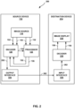
- input interface 228 may provide encoded image data 262 to decoder 230 (or to a MODEM that demodulates the bitstream, in some examples).
- Decoder 230 receives the encoded image data 262 from input interface 228. Decoder 230 decodes the encoded image data 262 to extract enhanced first view 156 and/or enhanced second view 158. Based on the enhanced first view 156 and/or the enhanced second view 158, image display 232, which is the same as or similar to image display 123, can render a two-dimensional or three-dimensional image. Although not shown in FIG. 2 , enhanced first view 156 and/or enhanced second view 158 may undergo additional processing at either source device 112 or destination device 214.
- Encoder 120 may perform intra- and inter-coding of video blocks within video slices.
- Intra-coding relies on spatial prediction to reduce or remove spatial redundancy in video within a given video frame or picture.
- Inter-coding relies on temporal prediction to reduce or remove temporal redundancy in video within adjacent frames or pictures of a video sequence.
- Intra-mode may refer to any of several spatial based coding modes.
- Inter-modes such as uni-directional prediction (P mode) or bi-prediction (B mode), may refer to any of several temporal-based coding modes.
- Encoder 120 may also generate a disparity map and/or a depth map using the inter-coding techniques described herein.
- encoder 120 receives a current image block within an image or a video frame to be encoded.
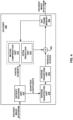
- encoder 120 includes mode select unit 340, reference frame memory 364, summer 350, transform processing unit 352, quantization unit 354, and entropy encoding unit 356.
- Mode select unit 340 includes motion estimation unit 342, motion compensation unit 344, intra-prediction unit 346, and partition unit 348.
- encoder 120 also includes inverse quantization unit 358, inverse transform unit 360, and summer 362.
- a deblocking filter (not shown in FIG. 3 ) may also be included to filter block boundaries to remove blockiness artifacts from reconstructed video.
- the deblocking filter would typically filter the output of summer 362. Additional filters (in loop or post loop) may also be used in addition to the deblocking filter. Such filters are not shown for brevity, but if desired, may filter the output of summer 350 (as an in-loop filter).
- encoder 120 receives an image, a video frame, or slice to be coded.
- the image, frame, or slice may be divided into multiple blocks.
- Motion estimation unit 342 and motion compensation unit 344 perform inter-predictive coding of the received block relative to one or more blocks in one or more reference frames to provide temporal prediction.
- Intra-prediction unit 346 may alternatively perform intra-predictive coding of the received block relative to one or more neighboring blocks in the same frame or slice as the block to be coded to provide spatial prediction.
- Encoder 120 may perform multiple coding passes (e.g., to select an appropriate coding mode for each block of video data).
- Motion estimation unit 342 and motion compensation unit 344 can be highly integrated, but are illustrated separately for conceptual purposes.
- Motion estimation or the prediction of motion information, performed by motion estimation unit 342 is the process of generating motion vectors, which estimate motion for video blocks.
- a motion vector for example, may indicate the displacement of a PU of a video block within a current video frame or picture relative to a predictive block within a reference frame (or other coded unit) relative to the current block being coded within the current frame (or other coded unit).
- a predictive block is a block that is found to closely match the block to be coded, in terms of pixel difference, which may be determined by sum of absolute difference (SAD), sum of square difference (SSD), or other difference metrics.
- encoder 120 may calculate values for sub-integer pixel positions of reference pictures stored in reference frame memory 64. For example, encoder 120 may interpolate values of one-quarter pixel positions, one-eighth pixel positions, or other fractional pixel positions of the reference picture. Therefore, motion estimation unit 342 may perform a motion search relative to the full pixel positions and fractional pixel positions and output a motion vector with fractional pixel precision.
- the motion estimation unit 342 generates a disparity map by comparing two images that are received in sequence (e.g., a left image and a right image) and determining disparity values for each portion (e.g., each pixel, each group of pixels, etc.) in the received images in a manner as described herein.
- the disparity values can be determined by analyzing the motion between two images.
- the motion estimation unit 342 can upscale the disparity map to generate a depth map.
- Motion compensation performed by motion compensation unit 344, may involve fetching or generating the predictive block based on the motion vector determined by motion estimation unit 342. Upon receiving the motion vector for the PU of the current video block, motion compensation unit 344 may locate the predictive block to which the motion vector points in one of the reference picture lists. Summer 350 forms a residual video block by subtracting pixel values of the predictive block from the pixel values of the current video block being coded, forming pixel difference values, as discussed below.
- motion estimation unit 342 can perform motion estimation relative to luma components, and motion compensation unit 344 can use motion vectors calculated based on the luma components for both chroma components and luma components.
- Mode select unit 340 may generate syntax elements associated with the video blocks and the video slice for use by decoder 230 in decoding the video blocks of the video slice.
- Intra-prediction unit 346 may intra-predict a current block, as an alternative to the inter-prediction performed by motion estimation unit 342 and motion compensation unit 344, in some embodiments.
- intra-prediction unit 346 may determine an intra-prediction mode to use to encode a current block.
- intra-prediction unit 346 may encode a current block using various intra-prediction modes (e.g., during separate encoding passes) and intra-prediction unit 346 (or mode select unit 340, in some examples) may select an appropriate intra-prediction mode to use from the tested modes.
- intra-prediction unit 346 may calculate rate-distortion values using a rate-distortion analysis for the various tested intra-prediction modes, and select the intra-prediction mode having the best rate-distortion characteristics among the tested modes.
- Rate-distortion analysis generally determines an amount of distortion (or error) between an encoded block and an original, unencoded block that was encoded to produce the encoded block, as well as a bitrate (that is, a number of bits) used to produce the encoded block.
- Intra-prediction unit 346 may calculate ratios from the distortions and rates for the various encoded blocks to determine which intra-prediction mode exhibits the best rate-distortion value for the block.
- intra-prediction unit 346 may provide information indicative of the selected intra-prediction mode for the block to entropy encoding unit 356.
- Entropy encoding unit 356 may encode the information indicating the selected intra-prediction mode.
- Encoder 120 may include in the transmitted bitstream configuration data, which may include a plurality of intra-prediction mode index tables and a plurality of modified intra-prediction mode index tables (also referred to as codeword mapping tables), definitions of encoding contexts for various blocks, and indications of a most probable intra-prediction mode, an intra-prediction mode index table, and a modified intra-prediction mode index table to use for each of the contexts.
- encoder 120 forms a residual video block by subtracting the prediction data provided by mode select unit 340 from the original video block being coded.
- Summer 350 represents the component or components that perform this subtraction operation.
- Transform processing unit 352 applies a transform, such as a DCT or a conceptually similar transform (e.g., wavelet transforms, integer transforms, sub-band transforms, etc.), to the residual block, producing a video block comprising residual transform coefficient values.
- the transform may convert the residual information from a pixel value domain to a transform domain, such as a frequency domain.
- Transform processing unit 352 may send the resulting transform coefficients to quantization unit 354.
- Quantization unit 354 quantizes the transform coefficients to further reduce bit rate.
- entropy encoding unit 356 entropy codes the quantized transform coefficients. For example, entropy encoding unit 356 may perform CAVLC, CABAC, SBAC, PIPE coding, or another entropy coding technique. In the case of context-based entropy coding, context may be based on neighboring blocks. Following the entropy coding by entropy encoding unit 356, the encoded bitstream may be transmitted to another device (e.g., decoder 230) or archived for later transmission or retrieval.
- another device e.g., decoder 230
- Inverse quantization unit 358 and inverse transform unit 360 apply inverse quantization and inverse transformation, respectively, to reconstruct the residual block in the pixel domain (e.g., for later use as a reference block).
- Motion compensation unit 344 may calculate a reference block by adding the residual block to a predictive block of one of the frames stored in reference frame memory 364.
- Motion compensation unit 344 may also apply one or more interpolation filters to the reconstructed residual block to calculate sub-integer pixel values for use in motion estimation.
- Summer 362 adds the reconstructed residual block to the motion compensated prediction block produced by motion compensation unit 344 to produce a reconstructed video block for storage in reference frame memory 364.
- the reconstructed video block may be used by motion estimation unit 342 and motion compensation unit 344 as a reference block to inter-code a block in a subsequent video frame.
- FIG. 4 is a block diagram illustrating an example of a decoder that may implement techniques in accordance with aspects described in this disclosure.
- Decoder 230 may be configured to perform any or all of the techniques of this disclosure.
- the motion compensation unit 472 may be configured to generate a disparity map and/or a depth map.
- aspects of this disclosure are not so limited.
- the techniques described in this disclosure may be shared among the various components of decoder 230.
- a processor (not shown) may be configured to perform any or all of the techniques described in this disclosure.
- decoder 230 includes an entropy decoding unit 470, motion compensation unit 472, intra prediction unit 474, inverse quantization unit 476, inverse transformation unit 478, reference frame memory 482, and summer 480.
- Decoder 230 may, in some examples, perform a decoding pass generally reciprocal to the encoding pass described with respect to encoder 120 ( FIG. 3 ).
- Motion compensation unit 472 may generate prediction data based on motion vectors received from entropy decoding unit 470, while intra-prediction unit 474 may generate prediction data based on intra-prediction mode indicators received from entropy decoding unit 470.
- decoder 230 receives an encoded image bitstream that represents blocks of an encoded image or video slice and associated syntax elements from encoder 120.
- Entropy decoding unit 470 of decoder 230 entropy decodes the bitstream to generate quantized coefficients, motion vectors or intra-prediction mode indicators, and/or other syntax elements.
- Entropy decoding unit 470 forwards the motion vectors and other syntax elements to motion compensation unit 472.
- Decoder 230 may receive the syntax elements at the image, video slice level, and/or the block level.
- intra prediction unit 474 may generate prediction data for a block of the current image or video slice based on a signaled intra prediction mode and data from previously decoded blocks of the current frame or picture.
- motion compensation unit 472 produces predictive blocks for a video block of the current video slice based on the motion vectors and other syntax elements received from entropy decoding unit 470.
- the predictive blocks may be produced from one of the reference pictures within one of the reference picture lists.
- Decoder 230 may construct the reference frame lists, List 0, List 1, and/or List C, using default construction techniques based on reference pictures stored in reference frame memory 482.
- Motion compensation unit 472 determines prediction information for a video block of the current video slice by parsing the motion vectors and other syntax elements, and uses the prediction information to produce the predictive blocks for the current video block being decoded.
- motion compensation unit 472 uses some of the received syntax elements to determine a prediction mode (e.g., intra- or inter-prediction) used to code the blocks of the video slice, an inter-prediction slice type (e.g., B slice, P slice, or GPB slice), construction information for one or more of the reference picture lists for the slice, motion vectors for each inter-encoded block of the image or slice, inter-prediction status for each inter-coded block of the image or slice, and/or other information to decode the blocks in the current image or video slice.
- a prediction mode e.g., intra- or inter-prediction
- an inter-prediction slice type e.g., B slice, P slice, or GPB slice
- the motion compensation unit 472 generates a disparity map by comparing two images that are received in sequence (e.g., a left image and a right image) and determining disparity values for each portion (e.g., each pixel, each group of pixels, etc.) in the received images in a manner as described herein.
- the disparity values can be determined by analyzing the motion between two images.
- the motion compensation unit 472 can upscale the disparity map to generate a depth map.
- Motion compensation unit 472 may also perform interpolation based on interpolation filters. Motion compensation unit 472 may use interpolation filters as used by encoder 120 during encoding of the video blocks to calculate interpolated values for sub-integer pixels of reference blocks. In this case, motion compensation unit 472 may determine the interpolation filters used by encoder 120 from the received syntax elements and use the interpolation filters to produce predictive blocks.
- Inverse quantization unit 476 inverse quantizes (e.g., de-quantizes) the quantized transform coefficients provided in the bitstream and decoded by entropy decoding unit 70.
- the inverse quantization process may include use of a quantization parameter QP Y calculated by encoder 120 for each video block in the video slice to determine a degree of quantization and, likewise, a degree of inverse quantization that should be applied.
- Inverse transform unit 478 applies an inverse transform (e.g., an inverse DCT), an inverse integer transform, or a conceptually similar inverse transform process, to the transform coefficients in order to produce residual blocks in the pixel domain.
- an inverse transform e.g., an inverse DCT
- an inverse integer transform e.g., an inverse integer transform
- a conceptually similar inverse transform process e.g., a conceptually similar inverse transform process
- inverse transform unit 478 may apply a 2-dimensional (2-D) inverse transform (in both the horizontal and vertical direction) to the coefficients. According to the techniques of this disclosure, inverse transform unit 478 may instead apply a horizontal 1-D inverse transform, a vertical 1-D inverse transform, or no transform to the residual data in each of the TUs.
- the type of transform applied to the residual data at encoder 120 may be signaled to decoder 230 to apply an appropriate type of inverse transform to the transform coefficients.
- decoder 230 forms a decoded video block by summing the residual blocks from inverse transform unit 478 with the corresponding predictive blocks generated by motion compensation unit 472.
- Summer 480 represents the component or components that perform this summation operation.
- a deblocking filter may also be applied to filter the decoded blocks in order to remove blockiness artifacts.
- Other loop filters may also be used to smooth pixel transitions, or otherwise improve the video quality.
- the decoded video blocks in a given frame or picture are then stored in reference picture memory 482, which stores reference pictures used for subsequent motion compensation.
- Reference frame memory 482 also stores decoded video for later presentation on a display device, such as image device 123 of FIG. 1 or image display 232 of FIG. 2 .
- encoders such as encoder 120. However, this is not meant to be limiting. The same techniques can be used by decoders, such as decoder 230, to accomplish similar results.
- Encoders such as encoder 120 convert raw video frames into standard compressed formats. The compression process is aided by a motion detection algorithm that computes pixelwise/blockwise motion for inter-coded frames.
- inter-coded frames can be of two types: P-frames and B-frames.
- P-frames contain forward motion values referring to a previous intra-coded frame (I-frame).
- B-frames contain bi-directional motion values, referring to previous and next intra-coded frames.
- An intra-coded frame is encoded spatially.
- An intra-coded frame is not associated with any motion values or any other frame in the stream.
- the motion value in an inter-coded frame is the disparity or difference between the two video frames.
- the depth filter may be a product of two Gaussian components: a spatial component (e.g., -e -(sd*sd)/ ⁇ s ) and an image color and depth value gradient component (e.g., e -(id*id)/ ⁇ c ), where ⁇ s and ⁇ c may decide a spread factor of the corresponding Gaussian kernel.
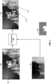
- the encoder 120 may carry out a plurality of filtering iterations on a previously filtered depth map to improve the depth map.
- the encoder 120 upscales the depth map 620 using sensor inputs. For example, the encoder 120 may create an initial estimate using a simple, bilinear upscale.
- processors such as one or more digital signal processors (DSPs), general purpose microprocessors, application specific integrated circuits (ASICs), field programmable logic arrays (FPGAs), or other equivalent integrated or discrete logic circuitry.
- DSPs digital signal processors
- ASICs application specific integrated circuits
- FPGAs field programmable logic arrays
- processors may refer to any of the foregoing structure or any other structure suitable for implementation of the techniques described herein.
- the functionality described herein may be provided within dedicated hardware and/or software modules configured for encoding and decoding, or incorporated in a combined codec. Also, the techniques could be fully implemented in one or more circuits or logic elements.
- the techniques of this disclosure may be implemented in a wide variety of devices or apparatuses, including a wireless handset, an integrated circuit (IC) or a set of ICs (e.g., a chip set).
- IC integrated circuit
- a set of ICs e.g., a chip set.
- Various components, modules, or units are described in this disclosure to emphasize functional aspects of devices configured to perform the disclosed techniques, but do not necessarily require realization by different hardware units. Rather, as described above, various units may be combined in a codec hardware unit or provided by a collection of interoperative hardware units, including one or more processors as described above, in conjunction with suitable software and/or firmware.
- Various examples have been described. These and other examples are within the scope of the following claims.
Landscapes
- Engineering & Computer Science (AREA)
- Physics & Mathematics (AREA)
- General Physics & Mathematics (AREA)
- Theoretical Computer Science (AREA)
- Multimedia (AREA)
- Signal Processing (AREA)
- Testing, Inspecting, Measuring Of Stereoscopic Televisions And Televisions (AREA)
- Processing Or Creating Images (AREA)
- Image Processing (AREA)
- Compression Or Coding Systems Of Tv Signals (AREA)
Claims (15)
- Verfahren zum Verbessern eines Bildes, wobei das Verfahren Folgendes beinhaltet:Abrufen (1402) eines linken Bildes (150) und eines rechten Bildes (152) aus einer Bildquelle (116), wobei das linke Bild und das rechte Bild jeweils dieselbe Szene aus unterschiedlichen Blickwinkeln darstellen;Bestimmen einer Tiefenkarte auf der Basis eines Unterschieds in der räumlichen Orientierung zwischen dem linken Bild und dem rechten Bild;Identifizieren eines von einem Benutzer ausgewählten Punkts des linken Bildes oder des rechten Bildes, wobei der ausgewählte Punkt mit einer ersten Tiefe assoziiert ist;Bestimmen (1408) einer den ausgewählten Punkt umgebenden Verbesserungsregion auf der Basis der bestimmten Tiefenkarte, wobei das Bestimmen der Verbesserungsregion das Beginnen an dem ausgewählten Punkt des linken Bildes oder des rechten Bildes und das Identifizieren, als die Verbesserungsregion, eines zusammenhängenden Teils des linken Bildes oder des rechten Bildes beinhaltet, der Pixel enthält, die an den ausgewählten Punkt angrenzen und eine Tiefe innerhalb eines Schwellenwerts der ersten Tiefe haben; undSchärfen (1410) nur der Verbesserungsregion.
- Verfahren nach Anspruch 1, das ferner das Verschlechtern eines nicht vom Benutzer ausgewählten Teils des linken Bildes oder des rechten Bildes beinhaltet.
- Verfahren nach Anspruch 2, wobei das Verschlechtern eines nicht vom Benutzer ausgewählten Teils des linken Bildes oder des rechten Bildes das Unscharfmachen des nicht vom Benutzer ausgewählten Teils des linken Bildes oder des rechten Bildes beinhaltet.
- Verfahren nach Anspruch 1, wobei das Bestimmen einer Tiefenkarte ferner Folgendes beinhaltet:Bestimmen einer Disparitätskarte auf der Basis des Unterschieds in der räumlichen Orientierung zwischen dem linken Bild und dem rechten Bild, wobei ein größerer Unterschied in der räumlichen Orientierung zwischen einem Teil des linken Bildes und dem rechten Bild eine höhere Disparität anzeigt;Hochskalieren der Disparitätskarte; undBestimmen der Tiefenkarte auf der Basis der hochskalierten Disparitätskarte.
- Verfahren nach Anspruch 4, wobei das Bestimmen einer Disparitätskarte das Bestimmen eines Abstands zwischen einem Block im linken Bild und einem entsprechenden Block im rechten Bild beinhaltet, wobei ein erster Block einem zweiten Block entspricht, wenn der erste Block und der zweite Block innerhalb eines Schwellenwerts identisch sind.
- Verfahren nach Anspruch 1, wobei das Bestimmen einer den ausgewählten Punkt umgebenden Verbesserungsregion ferner Folgendes beinhaltet:
Vergrößern der den ausgewählten Punkt umgebenden Verbesserungsregion, bis ein Teil des linken Bildes oder des rechten Bildes identifiziert ist, der keine Tiefe innerhalb des Schwellenwerts der ersten Tiefe hat. - Verfahren nach Anspruch 1, wobei das linke und/oder das rechte Bilder ein Standbild ist/sind.
- Vorrichtung zum Verbessern eines Bildes, wobei die Vorrichtung Folgendes umfasst:Mittel zum Abrufen (1402) eines linken Bildes (150) und eines rechten Bildes (152) aus einer Bildquelle (116), wobei das linke Bild und das rechte Bild jeweils dieselbe Szene aus unterschiedlichen Blickwinkeln darstellen;Mittel zum Bestimmen einer Tiefenkarte auf der Basis eines Unterschieds in der räumlichen Orientierung zwischen dem linken Bild und dem rechten Bild;Mittel zum Identifizieren eines von einem Benutzer ausgewählten Punkts des linken Bildes oder des rechten Bildes, wobei der ausgewählte Punkt mit einer ersten Tiefe assoziiert ist;Mittel zum Bestimmen (1408) einer den ausgewählten Punkt umgebenden Verbesserungsregion auf der Basis der bestimmten Tiefenkarte, wobei das Bestimmen der Verbesserungsregion das Beginnen an dem ausgewählten Punkt des linken Bildes oder des rechten Bildes und das Identifizieren, als die Verbesserungsregion, eines zusammenhängenden Teils des linken Bildes oder des rechten Bildes beinhaltet, der Pixel enthält, die an den ausgewählten Punkt angrenzen und eine Tiefe innerhalb eines Schwellenwerts der ersten Tiefe haben; undMittel zum Schärfen (1410) nur der Verbesserungsregion.
- Vorrichtung nach Anspruch 8, die ferner Mittel zum Verschlechtern eines vom Benutzer nicht ausgewählten Teils des linken Bildes oder des rechten Bildes umfasst,
wobei das Mittel zum Verschlechtern eines vom Benutzer nicht ausgewählten Teils des linken Bildes oder des rechten Bildes Mittel zum Unscharfmachen des vom Benutzer nicht ausgewählten Teils des linken Bildes oder rechten Bildes umfasst. - Vorrichtung nach Anspruch 8, wobei das Mittel zum Bestimmen einer Tiefenkarte ferner Folgendes umfasst:Mittel zum Bestimmen einer Disparitätskarte auf der Basis des Unterschieds in der räumlichen Orientierung zwischen dem linken Bild und dem rechten Bild, wobei ein größerer Unterschied in der räumlichen Orientierung zwischen einem Teil des linken Bildes und des rechten Bildes eine höhere Disparität anzeigt;Mittel zum Hochskalieren der Disparitätskarte; undMittel zum Bestimmen der Tiefenkarte auf der Basis der hochskalierten Disparitätskarte.
- Vorrichtung nach Anspruch 8, wobei das Mittel zum Bestimmen einer Disparitätskarte Mittel zum Bestimmen eines Abstands zwischen einem Block im linken Bild und einem entsprechenden Block im rechten Bild umfasst, wobei ein erster Block einem zweiten Block entspricht, wenn der erste Block und der zweite Block innerhalb eines Schwellenwerts identisch sind.
- Vorrichtung nach Anspruch 8, wobei das Mittel zum Bestimmen einer den ausgewählten Punkt umgebenden Verbesserungsregion ferner Folgendes umfasst:
Mittel zum Vergrößern der den ausgewählten Punkt umgebenden Verbesserungsregion, bis ein Teil des linken Bildes oder des rechten Bildes identifiziert ist, der keine Tiefe innerhalb des Schwellenwerts der ersten Tiefe hat. - Vorrichtung nach Anspruch 8, wobei das Mittel zum Abrufen und das Mittel zum Bestimmen einer Tiefenkarte einen Encoder umfassen, und wobei das Mittel zum Identifizieren, das Mittel zum Bestimmen einer Verbesserungsregion und das Mittel zum Verbessern einen Prozessor umfassen.
- Vorrichtung nach Anspruch 8, wobei das linke und/oder das rechte Bilder ein Standbild ist/sind.
- Nichtflüchtiges, computerlesbares Medium, das Code umfasst, der bei Ausführung durch eine einen Prozessor umfassende Vorrichtung die Vorrichtung zum Durchführen des Verfahrens nach einem der Ansprüche 1 bis 7 veranlasst.
Applications Claiming Priority (2)
| Application Number | Priority Date | Filing Date | Title |
|---|---|---|---|
| US14/201,261 US9552633B2 (en) | 2014-03-07 | 2014-03-07 | Depth aware enhancement for stereo video |
| PCT/US2015/017104 WO2015134222A1 (en) | 2014-03-07 | 2015-02-23 | Depth aware enhancement for stereo video |
Publications (3)
| Publication Number | Publication Date |
|---|---|
| EP3114643A1 EP3114643A1 (de) | 2017-01-11 |
| EP3114643B1 true EP3114643B1 (de) | 2025-07-09 |
| EP3114643C0 EP3114643C0 (de) | 2025-07-09 |
Family
ID=52630500
Family Applications (1)
| Application Number | Title | Priority Date | Filing Date |
|---|---|---|---|
| EP15708645.5A Active EP3114643B1 (de) | 2014-03-07 | 2015-02-23 | Tiefenbewusste verstärkung für stereovideo |
Country Status (6)
| Country | Link |
|---|---|
| US (1) | US9552633B2 (de) |
| EP (1) | EP3114643B1 (de) |
| JP (1) | JP6178017B2 (de) |
| KR (1) | KR101844705B1 (de) |
| CN (1) | CN106068527B (de) |
| WO (1) | WO2015134222A1 (de) |
Families Citing this family (33)
| Publication number | Priority date | Publication date | Assignee | Title |
|---|---|---|---|---|
| US9552633B2 (en) * | 2014-03-07 | 2017-01-24 | Qualcomm Incorporated | Depth aware enhancement for stereo video |
| US10057593B2 (en) * | 2014-07-08 | 2018-08-21 | Brain Corporation | Apparatus and methods for distance estimation using stereo imagery |
| WO2016025962A1 (en) * | 2014-08-15 | 2016-02-18 | The University Of Akron | Device and method for three-dimensional video communication |
| US9772405B2 (en) * | 2014-10-06 | 2017-09-26 | The Boeing Company | Backfilling clouds of 3D coordinates |
| US9569692B2 (en) | 2014-10-31 | 2017-02-14 | The Nielsen Company (Us), Llc | Context-based image recognition for consumer market research |
| US20160189355A1 (en) * | 2014-12-29 | 2016-06-30 | Dell Products, Lp | User controls for depth based image editing operations |
| US20160295194A1 (en) * | 2015-03-30 | 2016-10-06 | Ming Shi CO., LTD. | Stereoscopic vision system generatng stereoscopic images with a monoscopic endoscope and an external adapter lens and method using the same to generate stereoscopic images |
| WO2017014693A1 (en) * | 2015-07-21 | 2017-01-26 | Heptagon Micro Optics Pte. Ltd. | Generating a disparity map based on stereo images of a scene |
| US9761000B2 (en) * | 2015-09-18 | 2017-09-12 | Qualcomm Incorporated | Systems and methods for non-obstacle area detection |
| CN105354805B (zh) * | 2015-10-26 | 2020-03-06 | 京东方科技集团股份有限公司 | 深度图像的去噪方法和去噪设备 |
| US10451714B2 (en) | 2016-12-06 | 2019-10-22 | Sony Corporation | Optical micromesh for computerized devices |
| US10536684B2 (en) * | 2016-12-07 | 2020-01-14 | Sony Corporation | Color noise reduction in 3D depth map |
| US10495735B2 (en) | 2017-02-14 | 2019-12-03 | Sony Corporation | Using micro mirrors to improve the field of view of a 3D depth map |
| US10795022B2 (en) | 2017-03-02 | 2020-10-06 | Sony Corporation | 3D depth map |
| US10979687B2 (en) | 2017-04-03 | 2021-04-13 | Sony Corporation | Using super imposition to render a 3D depth map |
| US10484667B2 (en) | 2017-10-31 | 2019-11-19 | Sony Corporation | Generating 3D depth map using parallax |
| CN109753846A (zh) * | 2017-11-03 | 2019-05-14 | 北京深鉴智能科技有限公司 | 目标跟踪硬件实现系统和方法 |
| US10580151B2 (en) * | 2017-12-05 | 2020-03-03 | Qualcomm Incorporated | Tile-based low-resolution depth storage |
| JP7106859B2 (ja) * | 2017-12-27 | 2022-07-27 | トヨタ自動車株式会社 | 画像表示装置 |
| TWI719440B (zh) * | 2018-04-02 | 2021-02-21 | 聯發科技股份有限公司 | 立體匹配方法及相應立體匹配裝置 |
| CA3039701A1 (en) * | 2018-04-06 | 2019-10-06 | Comcast Cable Communications, Llc | Systems, methods, and apparatuses for processing video |
| US10498948B1 (en) | 2018-06-05 | 2019-12-03 | Applied Materials, Inc. | Methods and apparatus for absolute and relative depth measurements using camera focus distance |
| US10549186B2 (en) | 2018-06-26 | 2020-02-04 | Sony Interactive Entertainment Inc. | Multipoint SLAM capture |
| CN110728710B (zh) * | 2018-07-16 | 2023-10-27 | 株式会社理光 | 视觉里程计算方法、装置和计算机可读存储介质 |
| EP3629585A1 (de) * | 2018-09-25 | 2020-04-01 | Koninklijke Philips N.V. | Bildsynthese |
| WO2020072579A1 (en) * | 2018-10-02 | 2020-04-09 | Futurewei Technologies, Inc. | Motion estimation using 3d auxiliary data |
| CN109767466B (zh) * | 2019-01-10 | 2021-07-13 | 深圳看到科技有限公司 | 画面渲染方法、装置、终端及对应的存储介质 |
| WO2021230646A1 (en) * | 2020-05-12 | 2021-11-18 | Samsung Electronics Co., Ltd. | System and method for depth map recovery |
| US11468587B2 (en) | 2020-05-12 | 2022-10-11 | Samsung Electronics Co., Ltd. | System and method for depth map recovery |
| KR102717662B1 (ko) * | 2021-07-02 | 2024-10-15 | 주식회사 뷰웍스 | 스테레오 영상을 이용한 고심도 영상 생성 방법 및 장치, 고심도 영상 생성 모델 학습 장치 |
| WO2022036338A2 (en) * | 2021-11-09 | 2022-02-17 | Futurewei Technologies, Inc. | System and methods for depth-aware video processing and depth perception enhancement |
| CN114519710B (zh) * | 2022-02-22 | 2024-07-12 | 平安科技(深圳)有限公司 | 视差图生成方法和装置、电子设备及存储介质 |
| US20250139806A1 (en) * | 2023-10-25 | 2025-05-01 | Qualcomm Incorporated | Efficient local normalization for dfs |
Citations (2)
| Publication number | Priority date | Publication date | Assignee | Title |
|---|---|---|---|---|
| US20120269384A1 (en) * | 2011-04-19 | 2012-10-25 | Jones Michael J | Object Detection in Depth Images |
| US20140015919A1 (en) * | 2011-10-21 | 2014-01-16 | Navteq B.V. | Reimaging Based on Depthmap Information |
Family Cites Families (20)
| Publication number | Priority date | Publication date | Assignee | Title |
|---|---|---|---|---|
| EP1418766A3 (de) | 1998-08-28 | 2010-03-24 | Imax Corporation | Méthode et appareil pour le traitement d'images |
| US8401336B2 (en) * | 2001-05-04 | 2013-03-19 | Legend3D, Inc. | System and method for rapid image sequence depth enhancement with augmented computer-generated elements |
| AU2009273297B8 (en) * | 2008-07-21 | 2013-03-07 | Interdigital Madison Patent Holdings | Coding device for 3D video signals |
| EP2307854A1 (de) | 2008-07-31 | 2011-04-13 | Tele Atlas B.V. | Verfahren zum anzeigen von navigationsdaten in 3d |
| JP5444955B2 (ja) * | 2009-08-31 | 2014-03-19 | ソニー株式会社 | 立体画像表示システム、視差変換装置、視差変換方法およびプログラム |
| WO2011033673A1 (ja) * | 2009-09-18 | 2011-03-24 | 株式会社 東芝 | 画像処理装置 |
| US20100164952A1 (en) * | 2010-01-25 | 2010-07-01 | Michael Roderick | Stereoscopic image production method and system |
| US20130033586A1 (en) | 2010-04-21 | 2013-02-07 | Samir Hulyalkar | System, Method and Apparatus for Generation, Transmission and Display of 3D Content |
| JP5556394B2 (ja) * | 2010-06-07 | 2014-07-23 | ソニー株式会社 | 立体画像表示システム、視差変換装置、視差変換方法およびプログラム |
| US20120008852A1 (en) * | 2010-07-07 | 2012-01-12 | Himax Media Solutions, Inc. | System and method of enhancing depth of a 3d image |
| EP2450450A1 (de) * | 2010-11-09 | 2012-05-09 | Ineos Commercial Services UK Limited | Verfahren und Vorrichtung zur Produktion von Ethylen via Herstellung von Synthesegas |
| US8629901B2 (en) * | 2011-05-19 | 2014-01-14 | National Taiwan University | System and method of revising depth of a 3D image pair |
| US9007441B2 (en) | 2011-08-04 | 2015-04-14 | Semiconductor Components Industries, Llc | Method of depth-based imaging using an automatic trilateral filter for 3D stereo imagers |
| US20140333739A1 (en) * | 2011-12-02 | 2014-11-13 | Lg Electronics Inc | 3d image display device and method |
| EP2634772A1 (de) | 2012-02-28 | 2013-09-04 | BlackBerry Limited | Verfahren und Vorrichtungen zur Auswahl von Objekten auf Bildern |
| US9185387B2 (en) | 2012-07-03 | 2015-11-10 | Gopro, Inc. | Image blur based on 3D depth information |
| US20140043447A1 (en) * | 2012-08-09 | 2014-02-13 | Sony Corporation | Calibration in the loop |
| US20140104268A1 (en) * | 2012-10-15 | 2014-04-17 | Lenny Lipton | Method and apparatus for correcting stereoscopic display edge violations |
| CN104937927B (zh) * | 2013-02-20 | 2017-08-25 | 英特尔公司 | 2维图像或视频到3维立体图像或视频的实时自动转换 |
| US9552633B2 (en) * | 2014-03-07 | 2017-01-24 | Qualcomm Incorporated | Depth aware enhancement for stereo video |
-
2014
- 2014-03-07 US US14/201,261 patent/US9552633B2/en active Active
-
2015
- 2015-02-23 WO PCT/US2015/017104 patent/WO2015134222A1/en not_active Ceased
- 2015-02-23 KR KR1020167026748A patent/KR101844705B1/ko active Active
- 2015-02-23 JP JP2016555588A patent/JP6178017B2/ja active Active
- 2015-02-23 CN CN201580011468.3A patent/CN106068527B/zh active Active
- 2015-02-23 EP EP15708645.5A patent/EP3114643B1/de active Active
Patent Citations (2)
| Publication number | Priority date | Publication date | Assignee | Title |
|---|---|---|---|---|
| US20120269384A1 (en) * | 2011-04-19 | 2012-10-25 | Jones Michael J | Object Detection in Depth Images |
| US20140015919A1 (en) * | 2011-10-21 | 2014-01-16 | Navteq B.V. | Reimaging Based on Depthmap Information |
Also Published As
| Publication number | Publication date |
|---|---|
| US20150254811A1 (en) | 2015-09-10 |
| EP3114643A1 (de) | 2017-01-11 |
| CN106068527B (zh) | 2018-12-04 |
| US9552633B2 (en) | 2017-01-24 |
| KR101844705B1 (ko) | 2018-04-02 |
| CN106068527A (zh) | 2016-11-02 |
| WO2015134222A1 (en) | 2015-09-11 |
| KR20160130414A (ko) | 2016-11-11 |
| JP6178017B2 (ja) | 2017-08-09 |
| BR112016020544A8 (pt) | 2021-06-15 |
| BR112016020544A2 (pt) | 2017-08-15 |
| EP3114643C0 (de) | 2025-07-09 |
| JP2017512440A (ja) | 2017-05-18 |
Similar Documents
| Publication | Publication Date | Title |
|---|---|---|
| EP3114643B1 (de) | Tiefenbewusste verstärkung für stereovideo | |
| US20240406565A1 (en) | Image data encoding/decoding method and apparatus | |
| US20250350845A1 (en) | Image data encoding/decoding method and apparatus | |
| EP2491722B1 (de) | Verfahren zur erstellung von tiefenkarten zur umwandlung von 2d-videodaten in 3d-videodaten | |
| JP6026534B2 (ja) | 深度範囲の変動を伴う動き深度マップのコーディング | |
| CN104396250B (zh) | 用于3d视频译码的深度图的帧内译码的方法和装置 | |
| US20240406444A1 (en) | Image data encoding/decoding method and apparatus | |
| JP5698391B2 (ja) | マルチビュービデオプラス深度コンテンツのコーディング | |
| JP5805871B2 (ja) | 3次元ビデオコーデックにおける深度マップのためのスライスヘッダ予測 | |
| JP2021168479A (ja) | デプスマップの推定および更新を用いる効率的なマルチビュー符号化 | |
| US20240406447A1 (en) | Image data encoding/decoding method and apparatus | |
| US20250358527A1 (en) | Image data encoding/decoding method and apparatus | |
| US20160029038A1 (en) | Predictor for depth map intra coding | |
| KR20150010739A (ko) | 비대칭 텍스처 및 심도 분해능들에 기초한 뷰 합성 | |
| Zamarin et al. | Edge-preserving intra depth coding based on context-coding and H. 264/AVC | |
| BR112016020544B1 (pt) | Realce consciente de profundidade para vídeo estéreo | |
| WO2013159300A1 (en) | An apparatus, a method and a computer program for video coding and decoding | |
| Lucas et al. | E cient Predictive Algorithms for Image Compression | |
| HK1225881A1 (en) | Simplification of segment-wise dc coding of large prediction blocks in 3d video coding | |
| HK1225881B (zh) | 对3d视频译码中较大预测块的逐段dc译码的简化 |
Legal Events
| Date | Code | Title | Description |
|---|---|---|---|
| PUAI | Public reference made under article 153(3) epc to a published international application that has entered the european phase |
Free format text: ORIGINAL CODE: 0009012 |
|
| STAA | Information on the status of an ep patent application or granted ep patent |
Free format text: STATUS: REQUEST FOR EXAMINATION WAS MADE |
|
| 17P | Request for examination filed |
Effective date: 20160728 |
|
| AK | Designated contracting states |
Kind code of ref document: A1 Designated state(s): AL AT BE BG CH CY CZ DE DK EE ES FI FR GB GR HR HU IE IS IT LI LT LU LV MC MK MT NL NO PL PT RO RS SE SI SK SM TR |
|
| AX | Request for extension of the european patent |
Extension state: BA ME |
|
| DAX | Request for extension of the european patent (deleted) | ||
| STAA | Information on the status of an ep patent application or granted ep patent |
Free format text: STATUS: EXAMINATION IS IN PROGRESS |
|
| 17Q | First examination report despatched |
Effective date: 20200224 |
|
| REG | Reference to a national code |
Ref country code: DE Ref legal event code: R079 Free format text: PREVIOUS MAIN CLASS: G06T0005000000 Ipc: G06T0005500000 Ref country code: DE Ref legal event code: R079 Ref document number: 602015091966 Country of ref document: DE Free format text: PREVIOUS MAIN CLASS: G06T0005000000 Ipc: G06T0005500000 |
|
| GRAP | Despatch of communication of intention to grant a patent |
Free format text: ORIGINAL CODE: EPIDOSNIGR1 |
|
| STAA | Information on the status of an ep patent application or granted ep patent |
Free format text: STATUS: GRANT OF PATENT IS INTENDED |
|
| RIC1 | Information provided on ipc code assigned before grant |
Ipc: H04N 13/106 20180101ALI20240322BHEP Ipc: H04N 13/00 20060101ALI20240322BHEP Ipc: G06T 5/50 20060101AFI20240322BHEP |
|
| INTG | Intention to grant announced |
Effective date: 20240411 |
|
| GRAJ | Information related to disapproval of communication of intention to grant by the applicant or resumption of examination proceedings by the epo deleted |
Free format text: ORIGINAL CODE: EPIDOSDIGR1 |
|
| STAA | Information on the status of an ep patent application or granted ep patent |
Free format text: STATUS: EXAMINATION IS IN PROGRESS |
|
| INTC | Intention to grant announced (deleted) | ||
| GRAP | Despatch of communication of intention to grant a patent |
Free format text: ORIGINAL CODE: EPIDOSNIGR1 |
|
| STAA | Information on the status of an ep patent application or granted ep patent |
Free format text: STATUS: GRANT OF PATENT IS INTENDED |
|
| INTG | Intention to grant announced |
Effective date: 20240920 |
|
| GRAJ | Information related to disapproval of communication of intention to grant by the applicant or resumption of examination proceedings by the epo deleted |
Free format text: ORIGINAL CODE: EPIDOSDIGR1 |
|
| STAA | Information on the status of an ep patent application or granted ep patent |
Free format text: STATUS: EXAMINATION IS IN PROGRESS |
|
| GRAP | Despatch of communication of intention to grant a patent |
Free format text: ORIGINAL CODE: EPIDOSNIGR1 |
|
| STAA | Information on the status of an ep patent application or granted ep patent |
Free format text: STATUS: GRANT OF PATENT IS INTENDED |
|
| INTC | Intention to grant announced (deleted) | ||
| INTG | Intention to grant announced |
Effective date: 20250204 |
|
| GRAS | Grant fee paid |
Free format text: ORIGINAL CODE: EPIDOSNIGR3 |
|
| GRAA | (expected) grant |
Free format text: ORIGINAL CODE: 0009210 |
|
| STAA | Information on the status of an ep patent application or granted ep patent |
Free format text: STATUS: THE PATENT HAS BEEN GRANTED |
|
| AK | Designated contracting states |
Kind code of ref document: B1 Designated state(s): AL AT BE BG CH CY CZ DE DK EE ES FI FR GB GR HR HU IE IS IT LI LT LU LV MC MK MT NL NO PL PT RO RS SE SI SK SM TR |
|
| REG | Reference to a national code |
Ref country code: GB Ref legal event code: FG4D |
|
| REG | Reference to a national code |
Ref country code: CH Ref legal event code: EP |
|
| REG | Reference to a national code |
Ref country code: IE Ref legal event code: FG4D |
|
| REG | Reference to a national code |
Ref country code: DE Ref legal event code: R096 Ref document number: 602015091966 Country of ref document: DE |
|
| U01 | Request for unitary effect filed |
Effective date: 20250728 |
|
| U07 | Unitary effect registered |
Designated state(s): AT BE BG DE DK EE FI FR IT LT LU LV MT NL PT RO SE SI Effective date: 20250801 |