EP3114457B1 - Flow through debris sensor - Google Patents
Flow through debris sensor Download PDFInfo
- Publication number
- EP3114457B1 EP3114457B1 EP15710365.6A EP15710365A EP3114457B1 EP 3114457 B1 EP3114457 B1 EP 3114457B1 EP 15710365 A EP15710365 A EP 15710365A EP 3114457 B1 EP3114457 B1 EP 3114457B1
- Authority
- EP
- European Patent Office
- Prior art keywords
- sensor
- coil
- ferrous
- debris
- particles
- Prior art date
- Legal status (The legal status is an assumption and is not a legal conclusion. Google has not performed a legal analysis and makes no representation as to the accuracy of the status listed.)
- Active
Links
Images




Classifications
-
- G—PHYSICS
- G01—MEASURING; TESTING
- G01N—INVESTIGATING OR ANALYSING MATERIALS BY DETERMINING THEIR CHEMICAL OR PHYSICAL PROPERTIES
- G01N15/00—Investigating characteristics of particles; Investigating permeability, pore-volume or surface-area of porous materials
- G01N15/06—Investigating concentration of particle suspensions
- G01N15/0656—Investigating concentration of particle suspensions using electric, e.g. electrostatic methods or magnetic methods
-
- B—PERFORMING OPERATIONS; TRANSPORTING
- B03—SEPARATION OF SOLID MATERIALS USING LIQUIDS OR USING PNEUMATIC TABLES OR JIGS; MAGNETIC OR ELECTROSTATIC SEPARATION OF SOLID MATERIALS FROM SOLID MATERIALS OR FLUIDS; SEPARATION BY HIGH-VOLTAGE ELECTRIC FIELDS
- B03C—MAGNETIC OR ELECTROSTATIC SEPARATION OF SOLID MATERIALS FROM SOLID MATERIALS OR FLUIDS; SEPARATION BY HIGH-VOLTAGE ELECTRIC FIELDS
- B03C1/00—Magnetic separation
- B03C1/02—Magnetic separation acting directly on the substance being separated
- B03C1/28—Magnetic plugs and dipsticks
- B03C1/282—Magnetic plugs and dipsticks with associated accumulation indicator, e.g. Hall sensor
-
- B—PERFORMING OPERATIONS; TRANSPORTING
- B03—SEPARATION OF SOLID MATERIALS USING LIQUIDS OR USING PNEUMATIC TABLES OR JIGS; MAGNETIC OR ELECTROSTATIC SEPARATION OF SOLID MATERIALS FROM SOLID MATERIALS OR FLUIDS; SEPARATION BY HIGH-VOLTAGE ELECTRIC FIELDS
- B03C—MAGNETIC OR ELECTROSTATIC SEPARATION OF SOLID MATERIALS FROM SOLID MATERIALS OR FLUIDS; SEPARATION BY HIGH-VOLTAGE ELECTRIC FIELDS
- B03C1/00—Magnetic separation
- B03C1/02—Magnetic separation acting directly on the substance being separated
- B03C1/28—Magnetic plugs and dipsticks
- B03C1/286—Magnetic plugs and dipsticks disposed at the inner circumference of a recipient, e.g. magnetic drain bolt
-
- B—PERFORMING OPERATIONS; TRANSPORTING
- B03—SEPARATION OF SOLID MATERIALS USING LIQUIDS OR USING PNEUMATIC TABLES OR JIGS; MAGNETIC OR ELECTROSTATIC SEPARATION OF SOLID MATERIALS FROM SOLID MATERIALS OR FLUIDS; SEPARATION BY HIGH-VOLTAGE ELECTRIC FIELDS
- B03C—MAGNETIC OR ELECTROSTATIC SEPARATION OF SOLID MATERIALS FROM SOLID MATERIALS OR FLUIDS; SEPARATION BY HIGH-VOLTAGE ELECTRIC FIELDS
- B03C1/00—Magnetic separation
- B03C1/02—Magnetic separation acting directly on the substance being separated
- B03C1/30—Combinations with other devices, not otherwise provided for
-
- F—MECHANICAL ENGINEERING; LIGHTING; HEATING; WEAPONS; BLASTING
- F16—ENGINEERING ELEMENTS AND UNITS; GENERAL MEASURES FOR PRODUCING AND MAINTAINING EFFECTIVE FUNCTIONING OF MACHINES OR INSTALLATIONS; THERMAL INSULATION IN GENERAL
- F16N—LUBRICATING
- F16N29/00—Special means in lubricating arrangements or systems providing for the indication or detection of undesired conditions; Use of devices responsive to conditions in lubricating arrangements or systems
-
- F—MECHANICAL ENGINEERING; LIGHTING; HEATING; WEAPONS; BLASTING
- F16—ENGINEERING ELEMENTS AND UNITS; GENERAL MEASURES FOR PRODUCING AND MAINTAINING EFFECTIVE FUNCTIONING OF MACHINES OR INSTALLATIONS; THERMAL INSULATION IN GENERAL
- F16N—LUBRICATING
- F16N29/00—Special means in lubricating arrangements or systems providing for the indication or detection of undesired conditions; Use of devices responsive to conditions in lubricating arrangements or systems
- F16N29/04—Special means in lubricating arrangements or systems providing for the indication or detection of undesired conditions; Use of devices responsive to conditions in lubricating arrangements or systems enabling a warning to be given; enabling moving parts to be stopped
-
- G—PHYSICS
- G01—MEASURING; TESTING
- G01N—INVESTIGATING OR ANALYSING MATERIALS BY DETERMINING THEIR CHEMICAL OR PHYSICAL PROPERTIES
- G01N27/00—Investigating or analysing materials by the use of electric, electrochemical, or magnetic means
- G01N27/72—Investigating or analysing materials by the use of electric, electrochemical, or magnetic means by investigating magnetic variables
- G01N27/74—Investigating or analysing materials by the use of electric, electrochemical, or magnetic means by investigating magnetic variables of fluids
-
- G—PHYSICS
- G01—MEASURING; TESTING
- G01N—INVESTIGATING OR ANALYSING MATERIALS BY DETERMINING THEIR CHEMICAL OR PHYSICAL PROPERTIES
- G01N33/00—Investigating or analysing materials by specific methods not covered by groups G01N1/00 - G01N31/00
- G01N33/26—Oils; Viscous liquids; Paints; Inks
- G01N33/28—Oils, i.e. hydrocarbon liquids
-
- G—PHYSICS
- G01—MEASURING; TESTING
- G01N—INVESTIGATING OR ANALYSING MATERIALS BY DETERMINING THEIR CHEMICAL OR PHYSICAL PROPERTIES
- G01N33/00—Investigating or analysing materials by specific methods not covered by groups G01N1/00 - G01N31/00
- G01N33/26—Oils; Viscous liquids; Paints; Inks
- G01N33/28—Oils, i.e. hydrocarbon liquids
- G01N33/2835—Specific substances contained in the oils or fuels
- G01N33/2858—Metal particles
-
- F—MECHANICAL ENGINEERING; LIGHTING; HEATING; WEAPONS; BLASTING
- F16—ENGINEERING ELEMENTS AND UNITS; GENERAL MEASURES FOR PRODUCING AND MAINTAINING EFFECTIVE FUNCTIONING OF MACHINES OR INSTALLATIONS; THERMAL INSULATION IN GENERAL
- F16N—LUBRICATING
- F16N2200/00—Condition of lubricant
- F16N2200/04—Detecting debris, chips, swarfs
-
- F—MECHANICAL ENGINEERING; LIGHTING; HEATING; WEAPONS; BLASTING
- F16—ENGINEERING ELEMENTS AND UNITS; GENERAL MEASURES FOR PRODUCING AND MAINTAINING EFFECTIVE FUNCTIONING OF MACHINES OR INSTALLATIONS; THERMAL INSULATION IN GENERAL
- F16N—LUBRICATING
- F16N2250/00—Measuring
- F16N2250/32—Inductive
-
- F—MECHANICAL ENGINEERING; LIGHTING; HEATING; WEAPONS; BLASTING
- F16—ENGINEERING ELEMENTS AND UNITS; GENERAL MEASURES FOR PRODUCING AND MAINTAINING EFFECTIVE FUNCTIONING OF MACHINES OR INSTALLATIONS; THERMAL INSULATION IN GENERAL
- F16N—LUBRICATING
- F16N2250/00—Measuring
- F16N2250/50—Sampling
- F16N2250/52—Sampling magnetic
-
- G—PHYSICS
- G01—MEASURING; TESTING
- G01N—INVESTIGATING OR ANALYSING MATERIALS BY DETERMINING THEIR CHEMICAL OR PHYSICAL PROPERTIES
- G01N15/00—Investigating characteristics of particles; Investigating permeability, pore-volume or surface-area of porous materials
- G01N2015/0042—Investigating dispersion of solids
- G01N2015/0053—Investigating dispersion of solids in liquids, e.g. trouble
Definitions
- the present disclosure generally relates to an apparatus that may be configured to sense particles in a fluid medium.
- Sensed particles may include ferrous particles, conductive non-ferrous particles, and/or non-ferrous non-conductive particles.
- Debris sensors may be used in one or more of a variety of applications, which may include lubrication systems. As components and/or machines that may be connected to a lubrication system break down, particles of the components and/or machines may break off and flow with lubrication fluid. Detecting and/or measuring particles or debris in lubrication fluid may be useful for evaluating the physical condition of the components connected to the lubrication system. For example, and without limitation, increased amounts of debris may indicate an imminent failure and preventative steps may be taken to avoid complete failure.
- the present invention relates to a debris sensor according to claim 1.
- Preferred embodiments of the present invention are defined in the dependent claims.
- a debris sensor 10 includes a body 20, a first sensor 30, a collector 40, one or more magnets 50, 52, and a second sensor 60, and preferably also includes an indicating screen 70.
- Debris sensor 10 is configured for measuring and/or detecting ferrous particles 14, non-ferrous conductive particles 16, and preferably also non-ferrous non-conductive particles 114 in a fluid 12. Additionally, debris sensor 10 is configured to capture and/or filter particles from fluid 12.
- Body 20 may comprise one or more of a variety of shapes, sizes, and/or configurations.
- Body 20 may include a generally elongated shape and/or may be generally cylindrical.
- Body 20 may include a longitudinal and/or central axis 20A, an outer wall 20C, an inlet 24 at a first end and/or an outlet 26 at a second end.
- Body 20 may be configured to allow a fluid 12 to move between inlet 24 and outlet 26.
- First sensor 30 includes a ferrous particle sensor.
- First sensor 30 may include one or more electrical conductors.
- An electrical conductor may comprise one or more of a variety of shapes, sizes, and/or configurations.
- an electrical conductor may include a coil, which may be a sensing coil.
- first sensor 30 may include a first coil 32 and/or a second coil 34.
- a coil may be configured to sense changes in a magnetic field.
- first coil 32 and/or second coil 34 may be disposed in and/or in proximity to magnetic field 46 and/or changes to magnetic field 46 may induce an electromotive force (EMF) and/or a voltage in first coil 32 and/or second coil 34.
- EMF electromotive force
- first coil 32 and/or second coil 34 may comprise one or more of a variety of shapes, sizes, and/or configurations.
- first coil 32 and/or second coil 34 may have a generally annular, cylindrical, and/or helical shape.
- First coil 32 may have a longitudinal axis 32A and/or second coil 34 may have a longitudinal axis 34A.
- First coil 32 and/or second coil 34 may include and/or be disposed around a core (e.g., cores 32B, 34B), which may include, for example, a metal and/or ferrite core.
- a core e.g., cores 32B, 34B
- a core may or may not be magnetic and/or may increase a sensitivity of a coil to the generation of and/or changes to a magnetic field.
- first coil 32 and second coil 34 may be disposed in one or more of a variety of configurations.
- longitudinal axis 32A of first coil 32 and/or longitudinal axis 34A of second coil 34 may be disposed generally perpendicular to axis 20A and/or to a direction of the flow of fluid 12 (which may be generally aligned with axis 20A).
- first coil 32 and/or second coil 34 may not be arranged concentrically with each other and/or concentrically with body 20.
- first coil 32 and second coil 34 may be disposed so that they are generally axially aligned with each other (e.g., axis 32A and axis 34A may be aligned with each other).
- a portion 32C of first coil 32 and/or a portion 34C of second coil 34 may extend through outer wall 20C of body 20.
- first coil 32 and second coil 34 may be circumferentially spaced from each other relative to axis 20A.
- longitudinal axis 32A of first coil 32 may be circumferentially spaced (e.g., by about 90 degrees) from longitudinal axis 34A of second coil 34 relative to axis 20A.
- Circumferentially spaced coils e.g., first coil 32 and/or second coil 34
- first sensor 30 may include a coil (e.g., first coil 32) that may generally be configured for measuring characteristics of one or more ferrous particles (e.g., ferrous particles 14) in two dimensions.
- first coil 32 may be configured for measuring widths and lengths of ferrous particles 14.
- first sensor may include a coil (e.g., second coil 34) that may generally be configured for measuring characteristics of ferrous particles (e.g., ferrous particle 14) in two dimensions, at least one of which may be different than one of the two dimensions that may be measured by first coil 32.
- second coil 34 may be configured for measuring a height and a length of ferrous particles 14.
- first sensor 30 may include first coil 32 and second coil 34 that may be circumferentially spaced from each other relative to axis 20A, which may allow first sensor 30 to measure a size of ferrous particle 14 in three dimensions (e.g., length, width, and height).
- debris sensor 10 may be configured to reduce and/or minimize a saturation limit effect and/or increase a saturation limit relative to conventional debris sensors.
- a saturation limit may correspond to an amount and/or concentration of particles (e.g., ferrous particles 14) in fluid 12 at which sensor functionality may begin to degrade because the particles may at least partially cover a coil of a sensor.
- first coil 32 and/or second coil 34 may be configured to not attract ferrous particles 14 and/or to attract relatively few ferrous particles 14.
- first coil 32 and/or second coil 34 may include relatively few magnetic portions, may not include any magnetic portions, may include magnetic portions that are sufficiently far away from flowing ferrous particles 14 so the particles are not attracted, and/or may include magnetic portions that are sufficiently covered and/or shielded to not attract ferrous particles 14. Attracting relatively few and/or not attracting substantially any ferrous particles 14 may reduce and/or prevent a buildup of ferrous particles 14 on or near a coil (e.g., coil 32 and/or coil 34), which may increase a saturation limit of debris sensor 10 relative to conventional sensors. A buildup of ferrous particles 14 on a coil may interfere with a voltage induced in a coil and/or may reduce the accuracy and/or precision of a debris measurement.
- a coil e.g., coil 32 and/or coil 34
- debris sensor 10 includes a collector 40.
- Collector 40 is connected to body 20.
- Collector 40 may include a longitudinal axis 40A.
- collector 40 may include a threaded portion 40B that may correspond to a threaded portion of body 20, and which may permit collector 40 to be fastened to body 20 (e.g., aperture 20B may be threaded and/or configured to receive threaded portion 40B).
- Collector 40 includes a magnetic chip collector.
- Collector 40 is configured to capture particles (e.g., ferrous particles 14) and/or may include a magnet 42 that may comprise a magnetic material, such as, without limitation, samarium-cobalt and/or neodymium. Additionally or alternatively, magnet 42 may include an electromagnet and/or any material that may include magnetic properties.
- collector 40 may be configured to be removed and/or may permit evaluation of captured particles (e.g., ferrous particles 14 that may have been captured).
- Collector 40 may be configured to be removed during system 18 operation (e.g., without shutting a system 18 down for maintenance) and/or may include a feature 44, such as self-closing feature and/or valve, that may be configured to prevent fluid 12 from leaking out through collector 40 and/or through aperture 20B in body 20.
- collector 40 is disposed downstream of and/or closer to outlet 26 than first sensor 30, and/or collector 40 may be disposed between first sensor 30 and second sensor 60.
- Collector 40 is connected to a different portion of body 20 than first sensor 30 and collector 40 may be configured to operate partially and/or completely independently of first sensor 30 (e.g., collector 40 may be configured to operate in substantially the same manner in embodiments with a first sensor 30 and in embodiments without a first sensor 30).
- Collector 40 may comprise one or more of a variety of shapes, sizes, and/or configurations.
- Collector 40 may or may not be disposed generally axially aligned with first coil 32 and/or second coil 34, and/or collector 40 may be circumferentially spaced from first coil 32 and/or second coil 34 relative to axis 20A.
- axis 40A of collector 40 may extend radially outward relative to axis 20A at an angle of about 135 degrees from axis 32A of first coil 32 in a first direction and/or at an angle of about 135 degrees from axis 34A of second coil 34 in a second (e.g., opposite) direction.
- collector 40 may be configured as a source of a magnetic field 46 that may extend at least partially within body 20.
- Magnetic field 46 may, for purposes of general representation, correspond to magnetic field lines 48, such as generally illustrated in FIG. 1 .
- magnetic field 46 may be configured to be monitored by a first sensor 30.
- first coil 32 and/or second coil 34 of first sensor 30 may be configured such that changes in magnetic field 46 may induce a voltage and/or an electromotive force (EMF) in first coil 32 and/or second coil 34.
- EMF electromotive force
- first sensor 30 may be configured to cooperate with collector 40 to detect ferrous particles 14 in fluid 12. For example, and without limitation, if fluid 12 includes ferrous particles 14 and fluid 12 enters body 20, ferrous particles 14 may enter magnetic field 46. As ferrous particles 14 move in magnetic field 46, properties of magnetic field 46 are altered. Alterations of a magnetic field 46 may result in an induced electromotive force (EMF) and/or a induced voltage in a conductor in proximity to the magnetic field 46, such as, for example, first coil 32 and/or second coil 34 of first sensor 30.
- EMF induced electromotive force
- An induced EMF and/or voltage may be large enough and/or first sensor 30 may be sufficiently sensitive enough for first sensor 30 to detect and/or measure the induced EMF and/or generated voltage. Measured induced EMFs and/or voltages may correspond to various characteristics (e.g., sizes, masses, etc.) of ferrous particles 14 of fluid 12.
- collector 40 may be disposed sufficiently downstream of and/or closer to outlet 26 than first sensor 30, such that ferrous particles 14 do not build up on first sensor and/or may build up on, in, and/or near collector 40 without substantially affecting the function of first sensor 30.
- Debris sensor 10 includes a plurality of magnets (e.g., a first magnet 50 and/or a second magnet 52) that are disposed downstream of and/or closer to outlet 26 than first sensor 30 and/or collector 40.
- First magnet 50 may be connected to body 20 and/or may be disposed at least partially within body 20.
- a second magnet 52 may be connected to body 20 and/or may be disposed at least partially within body 20.
- First magnet 50 and second magnet 52 may be spaced (e.g., circumferentially) from each another and/or axis 50C of first magnet 50 and axis 52C of second magnet 52 may extend radially outwardly at an angle relative to each other.
- axis 50C of a first magnet 50 may extend radially outwardly at an angle of about 180 degrees from axis 52C of a second magnet 52.
- the plurality of magnets e.g., a first magnet 50 and/or a second magnet 52
- first magnet 50 may include a north pole 50A that may be generally directed away from an internal space 22 of body 20 (e.g., radially outward relative to axis 20A), first magnet 50 may include a south pole 50B that may be generally directed toward space 22 (e.g., radially inward relative to axis 20A toward a center of body 20), second magnet 52 may include a south pole 52B that may be generally directed away from space 22 (e.g., radially outward relative to axis 20A), and/or second magnet 52 may include a north pole 52A that may be generally directed toward space 22 (e.g., radially inward relative to axis 20A).
- Magnetic field 54 may exist at least between south pole 50B and north pole 52A and/or may correspond to magnetic field lines 56.
- Magnetic field 54 is configured to induce eddy currents in conductive particles 16 that move through magnetic field 54. Eddy currents in conductive particles 16 result in conductive particles 16 corresponding to magnetic fields 16A of their own, even if the conductive particles 16 do not include magnetic materials and/or are non-ferrous.
- first magnet 50 and/or second magnet 52 may be axially spaced and/or shielded from first sensor 30 and/or collector 40.
- first and second magnets 50, 52 may be sufficiently axially spaced and/or shielded from collector 40 such that magnetic field 46 and magnetic field 54 do not affect or do not substantially affect each other.
- Debris sensor 10 includes a second sensor 60.
- Second sensor 60 may comprise one or more of a variety of shapes, sizes, and/or configurations.
- second sensor 60 may be axially spaced and/or shielded from first sensor 30 and/or collector 40.
- second sensor 60 may be sufficiently axially spaced and/or shielded from collector 40 such that second sensor 60 is not affected or is not significantly affected by magnetic field 46.
- second sensor 60 may be disposed downstream of and/or closer to outlet 26 than first sensor 30, collector 40, first magnet 50, and/or second magnet 52.
- Second sensor 60 is configured to sense particles, such as, for example, non-ferrous and/or conductive particles 16. Second sensor 60 may be referred to herein as non-ferrous particle sensor 60. Second sensor 60 may include one or more electrical conductors. An electrical conductor may comprise one or more of a variety of shapes, sizes, and/or configurations. In embodiments, an electrical conductor may include a coil (e.g., first coil 62 and/or second coil 64).
- a coil e.g., first coil 62 and/or second coil 64.
- First coil 62 and/or second coil 64 may be configured to sense magnetic fields 16A that correspond to eddy currents induced in conductive particles 16.
- first coil 62 and/or second coil 64 may be disposed in proximity to magnetic fields 16A, and/or generation of and/or changes to magnetic fields 16A may induce an electromotive force (EMF) and/or a voltage in first coil 62 and/or second coil 64.
- EMF electromotive force
- first coil 62 and/or a second coil 64 may comprise one or more of a variety of shapes, sizes, and/or configurations.
- first coil 62 and/or second coil 64 may include a generally annular, cylindrical, and/or helical shape.
- First coil 62 may include a portion 62C that may at least partially extend into space 22 and/or second coil 64 may include a portion 64C that may at least partially extend into space 22.
- First coil 62 may include longitudinal axis 62A and/or second coil 64 may include longitudinal axis 64A.
- first coil 62 and/or longitudinal axis 64A of second coil 64 may be disposed generally perpendicular to axis 20A and/or first coil 62 and second coil 64 may be disposed so that they are generally axially aligned with each other along body 20.
- First coil 62 and/or second coil 64 may include and/or be disposed around a core (e.g., cores 62B, 64B), which may include, for example, a metal and/or ferrite core. Core 62B and/or core 64B may or may not include magnetic material and/or may increase a sensitivity of a coil.
- core 62B may increase the sensitivity of first coil 62 to generation of and/or changes to magnetic fields 16A
- core 64B may increase the sensitivity of second coil 64 to generation of and/or changes to magnetic fields 16A.
- Coils including an increased sensitivity to generation of and/or changes to magnetic fields may allow debris sensor 10 to include increased sensitivity to conductive particles 16, which may correspond to being able to detect and/or measure smaller particles, and/or may allow for more accurate and/or precise measurements of particles 16.
- first coil 62 and/or second coil 64 may be disposed in one or more of a variety of configurations. As generally illustrated in FIG. 3 , in embodiments, first coil 62 and second coil 64 may be circumferentially spaced from each other relative to axis 20A. For example, and without limitation, longitudinal axis 62A of first coil 62 may extend radially outward relative to axis 20A at angle of about 90 degrees from longitudinal axis 64A of second coil 64, which may allow debris sensor 10 to measure conductive particles 16 in three dimensions. In embodiments, first coil 62 and/or second coil 64 may be disposed generally circumferentially aligned with first magnet 50 and/or second magnet 52.
- first coil 62 may be circumferentially aligned with first magnet 50
- second magnet 52 may be circumferentially spaced from first coil 62 and first magnet 50 by about 180 degrees
- second coil 64 may be circumferentially spaced from first coil 62 and first magnet 50 by about 90 degrees in one direction and/or circumferentially spaced from second magnet 52 by about 90 degrees in another (e.g., opposite) direction.
- second sensor 60 may be configured to cooperate with first magnet 50 and/or second magnet 52 to sense and/or detect conductive particles 16. For example, if conductive particles 16 enter magnetic field 54, eddy currents may be induced in conductive particles 16, which may result in the generation of and/or changes to magnetic fields 16A corresponding to conductive particles 16. Magnetic fields 16A of conductive particles 16 may create and/or change a voltage and/or EMF induced in first coil 62 and/or in second coil 64. A degree of change in an induced voltage or EMF may correspond to a measure of conductive particles 16, such as, for example, a mass and/or size of conductive particles 16. In embodiments, first coil 62 and second coil 64 may be configured for measuring conductive particles 16 in three dimensions, such as, for example, length, width, and height dimensions of conductive particles 16.
- debris sensor 10 may include a screen 70.
- Screen 70 may be connected to and/or disposed at least partially in body 20. Screen 70 may be disposed downstream of first sensor 30, collector 40, magnets 50, 52, and/or second sensor 60. Screen 70 may be configured to capture particles, such as, for example, particles that may not have been captured by collector 40, which may include non-ferrous and/or conductive particles 16.
- screen 70 may be configured to be removed from debris sensor 10 and/or body 20 and/or may configured such that captured particles (e.g., conductive particles 16 that may have been captured) may be removed, for example, during a maintenance process of system 18.
- screen 70 may include an indicator screen and/or screen 70 may be configured to provide an indication of the presence of particles, such as, for example, conductive particles 16, which may be non-ferrous.
- Screen 70 may include an electrical resistance in the absence of conductive particles 16 and/or an electrical resistance of screen 70 may change if conductive particles 16 contact screen 70.
- conductive particles 16 may come into contact with screen 70 and/or conductive particles 16 may close previously open electrical circuits, which may change a resistance of screen 70.
- Debris sensor 10 may be configured to monitor the resistance of screen 70 for changes and/or to detect the presence of conductive particles 16 if a change in resistance is greater than a given threshold.
- screen 70 may be configured to provide an indication of the presence of non-ferrous non-conductive particles 114.
- Non-ferrous non-conductive particles 114 may, for example, include ceramic particles that may originate from a ceramic bearing that may be used by a machine 18C of system 18 ( see, e.g., FIG. 6 ).
- Screen 70 may include a capacitance, which may include being configured as a parallel plate capacitor having a capacitance.
- screen 70 may include a first plate 70A that may be upstream (e.g., closer to inlet 24) of a second plate 70B.
- non-ferrous non-conductive particles 114 may alter the characteristics of the matter between plates 70A, 70B of screen 70 (e.g., change dielectric characteristics) and/or alter the capacitance of screen 70.
- a change in capacitance may correspond to an amount of non-ferrous non-conductive particles 114 present at screen 70.
- Debris sensor 10 may be configured to monitor the capacitance of screen 70 for changes and/or to detect the presence of non-ferrous non-conductive particles 114 if a change in capacitance is greater than a given threshold.
- portions of screen 70 may be electrically insulated, which may reduce or eliminate the effect on the capacitance of screen 70 if a ferrous particle 14 and/or a conductive non-ferrous particle 16 contacts screen 70.
- screen 70 may be configured to capture particles (e.g., ferrous particles 14 not captured by collector 40, conductive particles 16, non-ferrous non-conductive particles 114, etc.) to allow fluid 12 to pass through, and/or may be configured as a filter.
- debris sensor 10 may capture via collector 40 some or all of any ferrous particles 14 that enter debris sensor 10 at inlet 24, and/or debris sensor 10 may capture and/or filter via screen 70 some or all of any other particles (e.g., conductive particles 16) and/or ferrous particles 14 not captured by collector 40 that may enter debris sensor 10.
- Debris sensor 10 may allow filtered fluid 12 to exit debris sensor 10 at outlet 26.
- debris sensor 10 may include and/or may be configured to be connected to a monitoring unit 90.
- Monitoring unit 90 may include a programmable microprocessor and/or microcontroller, and/or may include, for example, an application specific integrated circuit (ASIC).
- ASIC application specific integrated circuit
- Monitoring unit 90 may include a central processing unit (CPU), memory, and/or an input/output (I/O) interface.
- Monitoring unit 90 may be configured to perform various functions with appropriate programming instructions and/or code embodied in software, hardware, and/or other medium.
- monitoring unit 90 may include a Quantitative Debris Monitor (QDM) that may be digital.
- QDM Quantitative Debris Monitor
- Monitoring unit 90 may be configured to monitor one or more sensors (e.g., first sensor 30 and/or second sensor 60), a collector (e.g., collector 40), and/or a screen (e.g., screen 70).
- Monitoring unit 90 may be configured to receive signals and/or data from sensors (e.g., first sensor 30 and/or second sensor 60), collectors (e.g., collector 40), and/or screens (e.g., screen 70) to determine and/or calculate one or more characteristics of particles that may flow into debris sensor inlet 24.
- monitoring unit 90 may be configured to calculate a size of a ferrous particle 14 according to a voltage signal received/output from first sensor 30 and/or calculate a size of a non-ferrous particle 16 according to a voltage signal received/output from second sensor 60. Additionally or alternatively, monitoring unit 90 may be configured to determine a status of system 18 according to characteristics of particles (e.g., ferrous particles 14 and/or conductive particles 16) that may flow into debris sensor inlet 24.
- particles e.g., ferrous particles 14 and/or conductive particles 16
- monitoring unit 90 may be configured to indicate an imminent and/or an actual failure of a component of system 18 if a characteristic of sensed particles is outside of a predetermined range and/or exceeds a predetermined threshold (e.g., monitoring unit 90 senses that too many particles are present in fluid 12 and/or the particles in fluid 12 are too large).
- a predetermined range and/or a predetermined threshold may correspond to a normal/expected amount of particles and/or may be configured to reduce or prevent false alarms.
- monitoring unit 90 may include and/or be connected to a communication device 92.
- Communication device 92 may permit monitoring unit to communicate via a wired and/or wireless network to a remote location 94.
- communication device 92 may permit monitoring unit 90 to provide an indication of an imminent and/or actual failure to a remote location 94.
- a sensor may include a built-in-test (BIT) system 100.
- a BIT system 100 may be configured to test a function of first sensor 30 and/or second sensor 60.
- BIT system 100 may include a test coil (e.g., test coils 102A, 102B, 102C, 102D) disposed in first sensor 30 and/or test coil 102 may be in proximity to and/or wrapped around a primary coil (e.g., first coil 32, second coil 34, first coil 62, and/or second coil 64).
- BIT system 100 may be configured to provide a test signal via a test coil to a primary coil of a sensor.
- test coil 102A may be configured to test first coil 32
- test coil 102B may be configured to test second coil 34
- test coil 102C may be configured to test first coil 62
- test coil 102D may be configured to test second coil 64.
- a test signal may be configured to simulate the presence of ferrous particles 14 and/or conductive particles 16 in fluid 12.
- the response of a primary coil (e.g., coils 32, 34, 62, 64) to the test signal may be evaluated to assess the accuracy and/or precision of a primary coil.
- BIT system 100 may include an automatic BIT, which may be automatically activated if debris sensor 10, first sensor 30, and/or second sensor 60 is turned on, started up, and/or connected to a monitoring unit 90. Additionally or alternatively, BIT system 100 may be configured to allow a user to initiate a BIT at any time.
- body 20 may be disposed such that inlet 24 and/or outlet 26 may be in fluid connection with a particle separator, such as, for example, a cyclonic particle separator (e.g., particle separator 80 and/or particle separator 82).
- Particle separators 80, 82 may be configured to generally separate and/or concentrate particles in a volume of fluid (e.g., fluid 12) and direct them toward body 20.
- Body 20 may be disposed such fluid 12, which may include particles, may be directed from a particle separator 80, 82 toward inlet 24 and/or fluid 12 that has passed through body 20 may exit through outlet 26 and/or mix with fluid exiting the separator.
- Particle separators e.g., particle separator 82
- debris sensor 10 may be connected to a system 18, which may include a fluid reservoir 18A, a fluid pump 18B, a component and/or machine 18C in which fluid may be used, and/or a scavenge pump 18D.
- Debris sensor 10 may be configured to sense debris in fluid 12 received from scavenge pump 18D and/or provide filtered fluid to fluid reservoir 18A.
- debris sensor 10 may be disposed in an inline configuration in which all fluid 12 of system 18 flows through debris sensor, and/or debris sensor 10 may be disposed in a bypass configuration in which some of fluid 12 of system 18 flows through debris sensor 10 and some of fluid 12 does not flow through debris sensor 10.
- all of fluid 12 may enter a particle separator 80, 82 (see, e.g., FIGS. 4 and 5 ), and some of that fluid 12 may flow directly through particle separator 80, 82 back into a main fluid path of system 18, and some of fluid 12 may flow through debris sensor 10 before flowing back into the main fluid path of system 18.
- debris sensor 10 may be configured as a passive debris sensor.
- a debris sensor 10 may be configured without a signal generator and/or oscillator, may not consume electrical energy, and/or may not be connected to electrical power source.
Landscapes
- Chemical & Material Sciences (AREA)
- Engineering & Computer Science (AREA)
- Health & Medical Sciences (AREA)
- Life Sciences & Earth Sciences (AREA)
- Analytical Chemistry (AREA)
- General Physics & Mathematics (AREA)
- Immunology (AREA)
- Pathology (AREA)
- General Health & Medical Sciences (AREA)
- Physics & Mathematics (AREA)
- Biochemistry (AREA)
- General Engineering & Computer Science (AREA)
- Chemical Kinetics & Catalysis (AREA)
- General Chemical & Material Sciences (AREA)
- Oil, Petroleum & Natural Gas (AREA)
- Medicinal Chemistry (AREA)
- Food Science & Technology (AREA)
- Mechanical Engineering (AREA)
- Electrochemistry (AREA)
- Dispersion Chemistry (AREA)
- Investigating Or Analyzing Materials By The Use Of Magnetic Means (AREA)
Description
- The present disclosure generally relates to an apparatus that may be configured to sense particles in a fluid medium. Sensed particles may include ferrous particles, conductive non-ferrous particles, and/or non-ferrous non-conductive particles.
- Various articles sensors and sensing systems are disclosed in
US 4,731,578 A ,US 2009/0051350 A1 ,US 6,297,626 B1 ,US 5,708,198 A andUS 5,061,364 .
US 3,432,750 A discloses a debris sensor according to the preamble ofclaim 1. - Debris sensors may be used in one or more of a variety of applications, which may include lubrication systems. As components and/or machines that may be connected to a lubrication system break down, particles of the components and/or machines may break off and flow with lubrication fluid. Detecting and/or measuring particles or debris in lubrication fluid may be useful for evaluating the physical condition of the components connected to the lubrication system. For example, and without limitation, increased amounts of debris may indicate an imminent failure and preventative steps may be taken to avoid complete failure.
- Previous designs relating to measuring particles include
U.S. Patent Application No. 5,028,318 (Aslin ) which is assigned to the assignee of this application. - The present invention relates to a debris sensor according to
claim 1. Preferred embodiments of the present invention are defined in the dependent claims. - Embodiments of the invention will now be described, by way of example, with reference to the accompanying drawings, wherein:
-
FIG. 1 is a cross-sectional view of an embodiment of a debris sensor shown generally in accordance with teachings of the disclosure. -
FIG. 2 is a cross-sectional view of an embodiment of a debris sensor shown generally in accordance with teachings of the disclosure. -
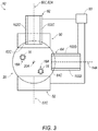
FIG. 3 is a cross-sectional view of an embodiment of a debris sensor shown generally in accordance with teachings of the disclosure. -
FIG. 4 is a cross-sectional view of another embodiment of a debris sensor and a particle separator shown generally in accordance with teachings of the disclosure. -
FIG. 5 is a cross-sectional view of another embodiment of a debris sensor and a particle separator shown generally in accordance with teachings of the disclosure. -
FIG. 6 is a schematic view of an embodiment of debris sensor connected to a system shown generally in accordance with teachings of the disclosure. - Reference will now be made in detail to embodiments of the present disclosure, examples of which are described herein and illustrated in the accompanying drawings. While the invention will be described in conjunction with embodiments, it will be understood that they are not intended to limit the present disclosure to these embodiments.
- Referring to
FIG. 1 , adebris sensor 10 includes abody 20, afirst sensor 30, acollector 40, one ormore magnets second sensor 60, and preferably also includes an indicatingscreen 70.Debris sensor 10 is configured for measuring and/or detectingferrous particles 14, non-ferrousconductive particles 16, and preferably also non-ferrousnon-conductive particles 114 in afluid 12. Additionally,debris sensor 10 is configured to capture and/or filter particles fromfluid 12. -
Body 20 may comprise one or more of a variety of shapes, sizes, and/or configurations.Body 20 may include a generally elongated shape and/or may be generally cylindrical.Body 20 may include a longitudinal and/orcentral axis 20A, anouter wall 20C, aninlet 24 at a first end and/or anoutlet 26 at a second end.Body 20 may be configured to allow afluid 12 to move betweeninlet 24 andoutlet 26. -
First sensor 30 includes a ferrous particle sensor.First sensor 30 may include one or more electrical conductors. An electrical conductor may comprise one or more of a variety of shapes, sizes, and/or configurations. In embodiments, an electrical conductor may include a coil, which may be a sensing coil. For example, and without limitation,first sensor 30 may include afirst coil 32 and/or asecond coil 34. A coil may be configured to sense changes in a magnetic field. For example,first coil 32 and/orsecond coil 34 may be disposed in and/or in proximity tomagnetic field 46 and/or changes tomagnetic field 46 may induce an electromotive force (EMF) and/or a voltage infirst coil 32 and/orsecond coil 34. - In embodiments,
first coil 32 and/orsecond coil 34 may comprise one or more of a variety of shapes, sizes, and/or configurations. For example, and without limitation,first coil 32 and/orsecond coil 34 may have a generally annular, cylindrical, and/or helical shape.First coil 32 may have alongitudinal axis 32A and/orsecond coil 34 may have alongitudinal axis 34A.First coil 32 and/orsecond coil 34 may include and/or be disposed around a core (e.g.,cores cores - In embodiments,
first coil 32 andsecond coil 34 may be disposed in one or more of a variety of configurations. For example, and without limitation,longitudinal axis 32A offirst coil 32 and/orlongitudinal axis 34A ofsecond coil 34 may be disposed generally perpendicular toaxis 20A and/or to a direction of the flow of fluid 12 (which may be generally aligned withaxis 20A). In embodiments,first coil 32 and/orsecond coil 34 may not be arranged concentrically with each other and/or concentrically withbody 20. In embodiments,first coil 32 andsecond coil 34 may be disposed so that they are generally axially aligned with each other (e.g.,axis 32A andaxis 34A may be aligned with each other). In embodiments, aportion 32C offirst coil 32 and/or aportion 34C ofsecond coil 34 may extend throughouter wall 20C ofbody 20. - As generally illustrated in
FIG. 2 , in embodiments,first coil 32 andsecond coil 34 may be circumferentially spaced from each other relative toaxis 20A. For example,longitudinal axis 32A offirst coil 32 may be circumferentially spaced (e.g., by about 90 degrees) fromlongitudinal axis 34A ofsecond coil 34 relative toaxis 20A. Circumferentially spaced coils (e.g.,first coil 32 and/or second coil 34) may allow or provide for determining a three dimensional aspect of sensed particles. In embodiments,first sensor 30 may include a coil (e.g., first coil 32) that may generally be configured for measuring characteristics of one or more ferrous particles (e.g., ferrous particles 14) in two dimensions. For example,first coil 32 may be configured for measuring widths and lengths offerrous particles 14. Additionally or alternatively, first sensor may include a coil (e.g., second coil 34) that may generally be configured for measuring characteristics of ferrous particles (e.g., ferrous particle 14) in two dimensions, at least one of which may be different than one of the two dimensions that may be measured byfirst coil 32. For example and without limitation,second coil 34 may be configured for measuring a height and a length offerrous particles 14. In embodiments,first sensor 30 may includefirst coil 32 andsecond coil 34 that may be circumferentially spaced from each other relative toaxis 20A, which may allowfirst sensor 30 to measure a size offerrous particle 14 in three dimensions (e.g., length, width, and height). - In embodiments,
debris sensor 10 may be configured to reduce and/or minimize a saturation limit effect and/or increase a saturation limit relative to conventional debris sensors. A saturation limit may correspond to an amount and/or concentration of particles (e.g., ferrous particles 14) influid 12 at which sensor functionality may begin to degrade because the particles may at least partially cover a coil of a sensor. In embodiments,first coil 32 and/orsecond coil 34 may be configured to not attractferrous particles 14 and/or to attract relatively fewferrous particles 14. For example,first coil 32 and/orsecond coil 34 may include relatively few magnetic portions, may not include any magnetic portions, may include magnetic portions that are sufficiently far away from flowingferrous particles 14 so the particles are not attracted, and/or may include magnetic portions that are sufficiently covered and/or shielded to not attractferrous particles 14. Attracting relatively few and/or not attracting substantially anyferrous particles 14 may reduce and/or prevent a buildup offerrous particles 14 on or near a coil (e.g.,coil 32 and/or coil 34), which may increase a saturation limit ofdebris sensor 10 relative to conventional sensors. A buildup offerrous particles 14 on a coil may interfere with a voltage induced in a coil and/or may reduce the accuracy and/or precision of a debris measurement. - As generally illustrated in
FIGS. 1 and2 ,debris sensor 10 includes acollector 40.Collector 40 is connected tobody 20.Collector 40 may include alongitudinal axis 40A. In embodiments,collector 40 may include a threadedportion 40B that may correspond to a threaded portion ofbody 20, and which may permitcollector 40 to be fastened to body 20 (e.g.,aperture 20B may be threaded and/or configured to receive threadedportion 40B).Collector 40 includes a magnetic chip collector.Collector 40 is configured to capture particles (e.g., ferrous particles 14) and/or may include amagnet 42 that may comprise a magnetic material, such as, without limitation, samarium-cobalt and/or neodymium. Additionally or alternatively,magnet 42 may include an electromagnet and/or any material that may include magnetic properties. - In embodiments,
collector 40 may be configured to be removed and/or may permit evaluation of captured particles (e.g.,ferrous particles 14 that may have been captured).Collector 40 may be configured to be removed duringsystem 18 operation (e.g., without shutting asystem 18 down for maintenance) and/or may include afeature 44, such as self-closing feature and/or valve, that may be configured to prevent fluid 12 from leaking out throughcollector 40 and/or throughaperture 20B inbody 20. - As generally illustrated in
FIG. 1 ,collector 40 is disposed downstream of and/or closer tooutlet 26 thanfirst sensor 30, and/orcollector 40 may be disposed betweenfirst sensor 30 andsecond sensor 60.Collector 40 is connected to a different portion ofbody 20 thanfirst sensor 30 andcollector 40 may be configured to operate partially and/or completely independently of first sensor 30 (e.g.,collector 40 may be configured to operate in substantially the same manner in embodiments with afirst sensor 30 and in embodiments without a first sensor 30).Collector 40 may comprise one or more of a variety of shapes, sizes, and/or configurations.Collector 40 may or may not be disposed generally axially aligned withfirst coil 32 and/orsecond coil 34, and/orcollector 40 may be circumferentially spaced fromfirst coil 32 and/orsecond coil 34 relative toaxis 20A. As generally illustrated inFIG. 2 , for example, and without limitation,axis 40A ofcollector 40 may extend radially outward relative toaxis 20A at an angle of about 135 degrees fromaxis 32A offirst coil 32 in a first direction and/or at an angle of about 135 degrees fromaxis 34A ofsecond coil 34 in a second (e.g., opposite) direction. - In embodiments, such as generally illustrated in
FIG. 1 ,collector 40 may be configured as a source of amagnetic field 46 that may extend at least partially withinbody 20.Magnetic field 46 may, for purposes of general representation, correspond tomagnetic field lines 48, such as generally illustrated inFIG. 1 . In embodiments,magnetic field 46 may be configured to be monitored by afirst sensor 30. For example,first coil 32 and/orsecond coil 34 offirst sensor 30 may be configured such that changes inmagnetic field 46 may induce a voltage and/or an electromotive force (EMF) infirst coil 32 and/orsecond coil 34. - In embodiments,
first sensor 30 may be configured to cooperate withcollector 40 to detectferrous particles 14 influid 12. For example, and without limitation, iffluid 12 includesferrous particles 14 andfluid 12 entersbody 20,ferrous particles 14 may entermagnetic field 46. Asferrous particles 14 move inmagnetic field 46, properties ofmagnetic field 46 are altered. Alterations of amagnetic field 46 may result in an induced electromotive force (EMF) and/or a induced voltage in a conductor in proximity to themagnetic field 46, such as, for example,first coil 32 and/orsecond coil 34 offirst sensor 30. An induced EMF and/or voltage may be large enough and/orfirst sensor 30 may be sufficiently sensitive enough forfirst sensor 30 to detect and/or measure the induced EMF and/or generated voltage. Measured induced EMFs and/or voltages may correspond to various characteristics (e.g., sizes, masses, etc.) offerrous particles 14 offluid 12. - In embodiments,
collector 40 may be disposed sufficiently downstream of and/or closer tooutlet 26 thanfirst sensor 30, such thatferrous particles 14 do not build up on first sensor and/or may build up on, in, and/ornear collector 40 without substantially affecting the function offirst sensor 30. -
Debris sensor 10 includes a plurality of magnets (e.g., afirst magnet 50 and/or a second magnet 52) that are disposed downstream of and/or closer tooutlet 26 thanfirst sensor 30 and/orcollector 40.First magnet 50 may be connected tobody 20 and/or may be disposed at least partially withinbody 20. Additionally or alternatively, asecond magnet 52 may be connected tobody 20 and/or may be disposed at least partially withinbody 20.First magnet 50 andsecond magnet 52 may be spaced (e.g., circumferentially) from each another and/oraxis 50C offirst magnet 50 andaxis 52C ofsecond magnet 52 may extend radially outwardly at an angle relative to each other. For example, and without limitation,axis 50C of afirst magnet 50 may extend radially outwardly at an angle of about 180 degrees fromaxis 52C of asecond magnet 52. The plurality of magnets (e.g., afirst magnet 50 and/or a second magnet 52) may cooperate and/or may be disposed such that a magnetic field (e.g., magnetic field 54) exists between two or more magnets. For example, and without limitation,first magnet 50 may include anorth pole 50A that may be generally directed away from aninternal space 22 of body 20 (e.g., radially outward relative toaxis 20A),first magnet 50 may include asouth pole 50B that may be generally directed toward space 22 (e.g., radially inward relative toaxis 20A toward a center of body 20),second magnet 52 may include asouth pole 52B that may be generally directed away from space 22 (e.g., radially outward relative toaxis 20A), and/orsecond magnet 52 may include anorth pole 52A that may be generally directed toward space 22 (e.g., radially inward relative toaxis 20A).Magnetic field 54 may exist at least betweensouth pole 50B andnorth pole 52A and/or may correspond to magnetic field lines 56. -
Magnetic field 54 is configured to induce eddy currents inconductive particles 16 that move throughmagnetic field 54. Eddy currents inconductive particles 16 result inconductive particles 16 corresponding tomagnetic fields 16A of their own, even if theconductive particles 16 do not include magnetic materials and/or are non-ferrous. - In embodiments,
first magnet 50 and/orsecond magnet 52 may be axially spaced and/or shielded fromfirst sensor 30 and/orcollector 40. For example, and without limitation, first andsecond magnets collector 40 such thatmagnetic field 46 andmagnetic field 54 do not affect or do not substantially affect each other. -
Debris sensor 10 includes asecond sensor 60.Second sensor 60 may comprise one or more of a variety of shapes, sizes, and/or configurations. In embodiments,second sensor 60 may be axially spaced and/or shielded fromfirst sensor 30 and/orcollector 40. For example, and without limitation,second sensor 60 may be sufficiently axially spaced and/or shielded fromcollector 40 such thatsecond sensor 60 is not affected or is not significantly affected bymagnetic field 46. In embodiments,second sensor 60 may be disposed downstream of and/or closer tooutlet 26 thanfirst sensor 30,collector 40,first magnet 50, and/orsecond magnet 52. -
Second sensor 60 is configured to sense particles, such as, for example, non-ferrous and/orconductive particles 16.Second sensor 60 may be referred to herein asnon-ferrous particle sensor 60.Second sensor 60 may include one or more electrical conductors. An electrical conductor may comprise one or more of a variety of shapes, sizes, and/or configurations. In embodiments, an electrical conductor may include a coil (e.g.,first coil 62 and/or second coil 64). -
First coil 62 and/orsecond coil 64 may be configured to sensemagnetic fields 16A that correspond to eddy currents induced inconductive particles 16. For example,first coil 62 and/orsecond coil 64 may be disposed in proximity tomagnetic fields 16A, and/or generation of and/or changes tomagnetic fields 16A may induce an electromotive force (EMF) and/or a voltage infirst coil 62 and/orsecond coil 64. - In embodiments, a
first coil 62 and/or asecond coil 64 may comprise one or more of a variety of shapes, sizes, and/or configurations. For example, and without limitation,first coil 62 and/orsecond coil 64 may include a generally annular, cylindrical, and/or helical shape.First coil 62 may include a portion 62C that may at least partially extend intospace 22 and/orsecond coil 64 may include aportion 64C that may at least partially extend intospace 22.First coil 62 may includelongitudinal axis 62A and/orsecond coil 64 may includelongitudinal axis 64A. In embodiments,longitudinal axis 62A offirst coil 62 and/orlongitudinal axis 64A ofsecond coil 64 may be disposed generally perpendicular toaxis 20A and/orfirst coil 62 andsecond coil 64 may be disposed so that they are generally axially aligned with each other alongbody 20.First coil 62 and/orsecond coil 64 may include and/or be disposed around a core (e.g.,cores Core 62B and/orcore 64B may or may not include magnetic material and/or may increase a sensitivity of a coil. For example, and without limitation,core 62B may increase the sensitivity offirst coil 62 to generation of and/or changes tomagnetic fields 16A, and/orcore 64B may increase the sensitivity ofsecond coil 64 to generation of and/or changes tomagnetic fields 16A. Coils including an increased sensitivity to generation of and/or changes to magnetic fields may allowdebris sensor 10 to include increased sensitivity toconductive particles 16, which may correspond to being able to detect and/or measure smaller particles, and/or may allow for more accurate and/or precise measurements ofparticles 16. - In embodiments,
first coil 62 and/orsecond coil 64 may be disposed in one or more of a variety of configurations. As generally illustrated inFIG. 3 , in embodiments,first coil 62 andsecond coil 64 may be circumferentially spaced from each other relative toaxis 20A. For example, and without limitation,longitudinal axis 62A offirst coil 62 may extend radially outward relative toaxis 20A at angle of about 90 degrees fromlongitudinal axis 64A ofsecond coil 64, which may allowdebris sensor 10 to measureconductive particles 16 in three dimensions. In embodiments,first coil 62 and/orsecond coil 64 may be disposed generally circumferentially aligned withfirst magnet 50 and/orsecond magnet 52. For example,first coil 62 may be circumferentially aligned withfirst magnet 50,second magnet 52 may be circumferentially spaced fromfirst coil 62 andfirst magnet 50 by about 180 degrees, and/orsecond coil 64 may be circumferentially spaced fromfirst coil 62 andfirst magnet 50 by about 90 degrees in one direction and/or circumferentially spaced fromsecond magnet 52 by about 90 degrees in another (e.g., opposite) direction. - In embodiments,
second sensor 60 may be configured to cooperate withfirst magnet 50 and/orsecond magnet 52 to sense and/or detectconductive particles 16. For example, ifconductive particles 16 entermagnetic field 54, eddy currents may be induced inconductive particles 16, which may result in the generation of and/or changes tomagnetic fields 16A corresponding toconductive particles 16.Magnetic fields 16A ofconductive particles 16 may create and/or change a voltage and/or EMF induced infirst coil 62 and/or insecond coil 64. A degree of change in an induced voltage or EMF may correspond to a measure ofconductive particles 16, such as, for example, a mass and/or size ofconductive particles 16. In embodiments,first coil 62 andsecond coil 64 may be configured for measuringconductive particles 16 in three dimensions, such as, for example, length, width, and height dimensions ofconductive particles 16. - In embodiments,
debris sensor 10 may include ascreen 70.Screen 70 may be connected to and/or disposed at least partially inbody 20.Screen 70 may be disposed downstream offirst sensor 30,collector 40,magnets second sensor 60.Screen 70 may be configured to capture particles, such as, for example, particles that may not have been captured bycollector 40, which may include non-ferrous and/orconductive particles 16. In embodiments,screen 70 may be configured to be removed fromdebris sensor 10 and/orbody 20 and/or may configured such that captured particles (e.g.,conductive particles 16 that may have been captured) may be removed, for example, during a maintenance process ofsystem 18. - In embodiments,
screen 70 may include an indicator screen and/orscreen 70 may be configured to provide an indication of the presence of particles, such as, for example,conductive particles 16, which may be non-ferrous.Screen 70 may include an electrical resistance in the absence ofconductive particles 16 and/or an electrical resistance ofscreen 70 may change ifconductive particles 16contact screen 70. For example, and without limitation,conductive particles 16 may come into contact withscreen 70 and/orconductive particles 16 may close previously open electrical circuits, which may change a resistance ofscreen 70.Debris sensor 10 may be configured to monitor the resistance ofscreen 70 for changes and/or to detect the presence ofconductive particles 16 if a change in resistance is greater than a given threshold. - In embodiments,
screen 70 may be configured to provide an indication of the presence of non-ferrousnon-conductive particles 114. Non-ferrousnon-conductive particles 114 may, for example, include ceramic particles that may originate from a ceramic bearing that may be used by amachine 18C of system 18 (see, e.g.,FIG. 6 ).Screen 70 may include a capacitance, which may include being configured as a parallel plate capacitor having a capacitance. For example, and without limitation,screen 70 may include afirst plate 70A that may be upstream (e.g., closer to inlet 24) of a second plate 70B. If non-ferrousnon-conductive particles 114reach screen 70, the non-ferrousnon-conductive particles 114 may alter the characteristics of the matter betweenplates 70A, 70B of screen 70 (e.g., change dielectric characteristics) and/or alter the capacitance ofscreen 70. A change in capacitance may correspond to an amount of non-ferrousnon-conductive particles 114 present atscreen 70.Debris sensor 10 may be configured to monitor the capacitance ofscreen 70 for changes and/or to detect the presence of non-ferrousnon-conductive particles 114 if a change in capacitance is greater than a given threshold. In embodiments, portions of screen 70 (e.g.,upstream plate 70A) may be electrically insulated, which may reduce or eliminate the effect on the capacitance ofscreen 70 if aferrous particle 14 and/or a conductivenon-ferrous particle 16contacts screen 70. - In embodiments, such as generally illustrated in
FIGS. 1 ,3 , and4 ,screen 70 may be configured to capture particles (e.g.,ferrous particles 14 not captured bycollector 40,conductive particles 16, non-ferrousnon-conductive particles 114, etc.) to allowfluid 12 to pass through, and/or may be configured as a filter. For example, and without limitation,debris sensor 10 may capture viacollector 40 some or all of anyferrous particles 14 that enterdebris sensor 10 atinlet 24, and/ordebris sensor 10 may capture and/or filter viascreen 70 some or all of any other particles (e.g., conductive particles 16) and/orferrous particles 14 not captured bycollector 40 that may enterdebris sensor 10.Debris sensor 10 may allow filteredfluid 12 to exitdebris sensor 10 atoutlet 26. - In embodiments, such as generally illustrated in
FIGS. 1 and4 ,debris sensor 10 may include and/or may be configured to be connected to amonitoring unit 90. Monitoringunit 90 may include a programmable microprocessor and/or microcontroller, and/or may include, for example, an application specific integrated circuit (ASIC). Monitoringunit 90 may include a central processing unit (CPU), memory, and/or an input/output (I/O) interface. Monitoringunit 90 may be configured to perform various functions with appropriate programming instructions and/or code embodied in software, hardware, and/or other medium. - In embodiments, monitoring
unit 90 may include a Quantitative Debris Monitor (QDM) that may be digital. Monitoringunit 90 may be configured to monitor one or more sensors (e.g.,first sensor 30 and/or second sensor 60), a collector (e.g., collector 40), and/or a screen (e.g., screen 70). Monitoringunit 90 may be configured to receive signals and/or data from sensors (e.g.,first sensor 30 and/or second sensor 60), collectors (e.g., collector 40), and/or screens (e.g., screen 70) to determine and/or calculate one or more characteristics of particles that may flow intodebris sensor inlet 24. For example, and without limitation, monitoringunit 90 may be configured to calculate a size of aferrous particle 14 according to a voltage signal received/output fromfirst sensor 30 and/or calculate a size of anon-ferrous particle 16 according to a voltage signal received/output fromsecond sensor 60. Additionally or alternatively, monitoringunit 90 may be configured to determine a status ofsystem 18 according to characteristics of particles (e.g.,ferrous particles 14 and/or conductive particles 16) that may flow intodebris sensor inlet 24. For example, and without limitation, monitoringunit 90 may be configured to indicate an imminent and/or an actual failure of a component ofsystem 18 if a characteristic of sensed particles is outside of a predetermined range and/or exceeds a predetermined threshold (e.g., monitoringunit 90 senses that too many particles are present influid 12 and/or the particles influid 12 are too large). A predetermined range and/or a predetermined threshold may correspond to a normal/expected amount of particles and/or may be configured to reduce or prevent false alarms. - In embodiments, such as generally illustrated in
FIG. 1 , monitoringunit 90 may include and/or be connected to acommunication device 92.Communication device 92 may permit monitoring unit to communicate via a wired and/or wireless network to aremote location 94. For example, and without limitation,communication device 92 may permit monitoringunit 90 to provide an indication of an imminent and/or actual failure to aremote location 94. - In embodiments, such as generally illustrated in
FIGS. 2 and3 , a sensor (e.g.,first sensor 30 and/or second sensor 60) may include a built-in-test (BIT)system 100. ABIT system 100 may be configured to test a function offirst sensor 30 and/orsecond sensor 60.BIT system 100 may include a test coil (e.g.,test coils first sensor 30 and/or test coil 102 may be in proximity to and/or wrapped around a primary coil (e.g.,first coil 32,second coil 34,first coil 62, and/or second coil 64).BIT system 100 may be configured to provide a test signal via a test coil to a primary coil of a sensor. For example, and without limitation,test coil 102A may be configured to testfirst coil 32,test coil 102B may be configured to testsecond coil 34, test coil 102C may be configured to testfirst coil 62, and/ortest coil 102D may be configured to testsecond coil 64. A test signal may be configured to simulate the presence offerrous particles 14 and/orconductive particles 16 influid 12. The response of a primary coil (e.g., coils 32, 34, 62, 64) to the test signal may be evaluated to assess the accuracy and/or precision of a primary coil.BIT system 100 may include an automatic BIT, which may be automatically activated ifdebris sensor 10,first sensor 30, and/orsecond sensor 60 is turned on, started up, and/or connected to amonitoring unit 90. Additionally or alternatively,BIT system 100 may be configured to allow a user to initiate a BIT at any time. - In embodiments, such as generally illustrated in
FIGS. 4 and5 ,body 20 may be disposed such thatinlet 24 and/oroutlet 26 may be in fluid connection with a particle separator, such as, for example, a cyclonic particle separator (e.g.,particle separator 80 and/or particle separator 82).Particle separators body 20.Body 20 may be disposedsuch fluid 12, which may include particles, may be directed from aparticle separator inlet 24 and/orfluid 12 that has passed throughbody 20 may exit throughoutlet 26 and/or mix with fluid exiting the separator. Particle separators (e.g., particle separator 82) may, additionally or alternatively, be configured toseparate air 110 fromfluid 12, for example, as generally illustrated inFIG. 5 . - As generally illustrated in
FIG. 6 , in embodiments,debris sensor 10 may be connected to asystem 18, which may include afluid reservoir 18A, afluid pump 18B, a component and/ormachine 18C in which fluid may be used, and/or ascavenge pump 18D.Debris sensor 10 may be configured to sense debris influid 12 received fromscavenge pump 18D and/or provide filtered fluid tofluid reservoir 18A. In embodiments,debris sensor 10 may be disposed in an inline configuration in which allfluid 12 ofsystem 18 flows through debris sensor, and/ordebris sensor 10 may be disposed in a bypass configuration in which some offluid 12 ofsystem 18 flows throughdebris sensor 10 and some offluid 12 does not flow throughdebris sensor 10. For example, and without limitation, all offluid 12 may enter aparticle separator 80, 82 (see, e.g.,FIGS. 4 and5 ), and some of that fluid 12 may flow directly throughparticle separator system 18, and some offluid 12 may flow throughdebris sensor 10 before flowing back into the main fluid path ofsystem 18. - In embodiments,
debris sensor 10 may be configured as a passive debris sensor. For example, and without limitation, in embodiments, adebris sensor 10 may be configured without a signal generator and/or oscillator, may not consume electrical energy, and/or may not be connected to electrical power source. - The foregoing descriptions of specific embodiments of the present disclosure have been presented for purposes of illustration and description. They are not intended to be exhaustive or to limit the present disclosure to the precise forms disclosed, and various modifications and variations are possible in light of the above teaching. For example, and without limitation, it should be understood that references to a coil are not limited to a specific shape and/or configuration. The embodiments were chosen and described in order to explain the principles of the invention and its practical application, to thereby enable others skilled in the art to utilize the present disclosure and various embodiments with various modifications as are suited to the particular use contemplated. It is intended that the scope of the present disclosure be defined by the claims.
Claims (11)
- A debris sensor (10), comprising:a body (20) including a first end and a second end;a magnetic chip collector (40) connected to the body, wherein the magnetic chip collector is configured as a source of a magnetic field so as to capture ferrous particles;a ferrous particle sensor (30) connected to the body,wherein the ferrous particle sensor is configured to sense changes in the magnetic field (46) caused by ferrous particles (14) in the magnetic field;a conductive particle sensor (60) connected to the body,characterized in that:the magnetic chip collector (40) is connected to the body at a position closer to the second end than the ferrous particle sensor (30), anda plurality of magnets (50, 52) is disposed closer to the second end than the magnetic chip collector;wherein a sensing coil (62, 64) of the conductive particle sensor (60) is configured to sense magnetic fields generated by eddy currents created in conductive particles (16) as the conductive particles flow through a magnetic field created by the plurality of magnets (50, 52).
- The debris sensor (10) of claim 1, comprising an indicator screen (70) downstream of the conductive particle sensor (60).
- The debris sensor (10) of claim 1, wherein the plurality of magnets (50, 52) includes a first magnet (50) with a south pole (50B) directed toward a center of the body (20) and a second magnet (52) with a north pole (52A) directed toward the center of the body.
- The debris sensor (10) of claim 1, wherein the ferrous particle sensor (30) includes a pair of sensing coils (32, 34), and wherein the pair of sensing coils preferably are disposed about 90 degrees apart from each other.
- The debris sensor (10) of claim 1, wherein the ferrous particle sensor (30) includes a sensing coil (32, 34) disposed perpendicularly to a longitudinal axis (20A) of the body (20).
- The debris sensor (10) of claim 1, wherein the ferrous particle sensor (30) includes a sensing coil (32, 34) that includes a longitudinal axis (32A, 34A) aligned perpendicularly to a longitudinal (20A) axis of the body (20).
- The debris sensor (10) of claim 1, comprising a built-in-test system (100) configured to generate a test signal to simulate a ferrous particle (14) and/or a conductive particle (16) being in proximity to the ferrous particle sensor (30) and the conductive particle sensor (60).
- The debris sensor (10) of claim 1, wherein the ferrous particle sensor (30) is configured to output signals to be processed by a digital quantitative debris monitor (90).
- The debris sensor (10) of claim 1, wherein the debris sensor is configured to be connected to a particle separator (80, 82), and wherein the particle separator preferably includes a cyclonic particle separator.
- The debris sensor (10) of claim 1, wherein the body (20) includes an inlet (24) and an outlet (26), and wherein body is configured to receive particle-filled fluid (12) at its inlet.
- The debris sensor (10) of claim 1, wherein the ferrous particle sensor (30) includes a first coil (32) and a second coil (34); the first coil and the second coil are circumferentially spaced from each other by about 90 degrees; the magnetic chip collector (40) is circumferentially spaced from the first coil by about 135 degrees in a first direction; and, the magnetic chip collector is circumferentially spaced from the second coil by about 135 degrees in a second direction.
Applications Claiming Priority (2)
| Application Number | Priority Date | Filing Date | Title |
|---|---|---|---|
| US201461947710P | 2014-03-04 | 2014-03-04 | |
| PCT/US2015/018723 WO2015134602A1 (en) | 2014-03-04 | 2015-03-04 | Flow through debris sensor |
Publications (2)
| Publication Number | Publication Date |
|---|---|
| EP3114457A1 EP3114457A1 (en) | 2017-01-11 |
| EP3114457B1 true EP3114457B1 (en) | 2019-01-16 |
Family
ID=52684712
Family Applications (1)
| Application Number | Title | Priority Date | Filing Date |
|---|---|---|---|
| EP15710365.6A Active EP3114457B1 (en) | 2014-03-04 | 2015-03-04 | Flow through debris sensor |
Country Status (3)
| Country | Link |
|---|---|
| US (1) | US10254210B2 (en) |
| EP (1) | EP3114457B1 (en) |
| WO (1) | WO2015134602A1 (en) |
Cited By (2)
| Publication number | Priority date | Publication date | Assignee | Title |
|---|---|---|---|---|
| DE102019207106A1 (en) * | 2019-05-16 | 2020-11-19 | Zf Friedrichshafen Ag | Cyclone with particle sensor |
| WO2024120753A1 (en) * | 2022-12-09 | 2024-06-13 | Airbus Helicopters Technik Gmbh | System and method for detecting the presence of and analysing particles in a lubricant flow |
Families Citing this family (26)
| Publication number | Priority date | Publication date | Assignee | Title |
|---|---|---|---|---|
| US10233773B2 (en) * | 2015-11-17 | 2019-03-19 | United Technologies Corporation | Monitoring system for non-ferrous metal particles |
| US10648361B2 (en) | 2016-07-26 | 2020-05-12 | United Technologies Corporation | Oil debris monitor with sequential coil system and associated algorithms for particle confirmation |
| US10317354B2 (en) | 2016-08-01 | 2019-06-11 | Pratt & Whitney Canada Corp. | Systems and methods for detecting chips in fluid of aircraft engine |
| BE1024987B1 (en) * | 2017-02-15 | 2018-09-14 | Safran Aero Boosters S.A. | METHOD AND SYSTEM FOR DETECTING DEBRIS FOR TURBOMACHINE |
| RU2668513C1 (en) * | 2017-03-29 | 2018-10-01 | Федеральное государственное бюджетное учреждение науки Институт проблем управления сложными системами Российской академии наук (ИПУСС РАН) | Metal particles detection in the friction units lubrication system oil and the oil flow speed determining method |
| US10866201B2 (en) * | 2017-11-29 | 2020-12-15 | Pratt & Whitney Canada Corp. | Lubricant debris monitoring system for gas turbine engine |
| DE102018207441B4 (en) * | 2018-05-15 | 2022-08-18 | Bayerische Motoren Werke Aktiengesellschaft | Method for analyzing the particles contained in an operating fluid of a device and device for carrying out the method |
| RU187036U1 (en) * | 2018-08-09 | 2019-02-14 | Публичное Акционерное Общество "Одк-Сатурн" | SIGNAL OF THE PRESENCE OF METAL PARTICLES IN THE LUBRICATION SYSTEM |
| RU2720147C1 (en) * | 2019-10-28 | 2020-04-24 | Акционерное общество "ОДК-Климов" | Method of chips in oil detecting and device for its implementation |
| RU2727737C1 (en) * | 2019-12-03 | 2020-07-23 | Акционерное общество "ОДК-Климов" | Method of chips detecting in oil and device for its implementation |
| FR3109197B1 (en) * | 2020-04-08 | 2022-04-29 | Safran Aircraft Engines | Lubricant monitoring system and method for its use |
| FR3109198B1 (en) * | 2020-04-08 | 2023-05-26 | Safran Aircraft Engines | Analysis device for detecting solid particles in a lubricant |
| BE1028211B1 (en) * | 2020-04-14 | 2021-11-16 | Safran Aero Boosters | OIL MONITORING OF A LUBRICATION DEVICE |
| RU2749574C1 (en) * | 2020-06-26 | 2021-06-15 | Федеральное государственное бюджетное учреждение науки Самарский федеральный исследовательский центр Российской академии наук (СамНЦ РАН) | Method for determining oil flow speed upon detection of metal particles in diagnostic means for friction units of gas turbine engines |
| RU2765325C1 (en) * | 2021-03-10 | 2022-01-28 | Акционерное общество "ОДК-Климов" | Method for signaling the presence of chippings in oil and a device for its implementation |
| BE1029383B1 (en) * | 2021-05-06 | 2022-12-05 | Safran Aero Boosters | DEBRIS ATTRACTION AND DETECTION MODULE |
| US20230143925A1 (en) * | 2021-11-07 | 2023-05-11 | Pall Corporation | Method of monitoring with metal debris sensor assembly |
| US20230146993A1 (en) * | 2021-11-07 | 2023-05-11 | Pall Corporation | Wear detection system with metal debris sensor assembly |
| US20230147354A1 (en) * | 2021-11-07 | 2023-05-11 | Pall Corporation | Filter with metal debris sensor assembly |
| US12535446B2 (en) | 2023-05-24 | 2026-01-27 | Pratt & Whitney Canada Corp. | Capacitive chip detector |
| US12158048B1 (en) | 2023-05-31 | 2024-12-03 | Halliburton Energy Services, Inc. | Debris capturing magnet with real time debris capacity monitoring |
| EP4729921A1 (en) * | 2023-09-25 | 2026-04-22 | LG Energy Solution, Ltd. | Metal particle monitoring device and method thereof |
| EP4585922A1 (en) * | 2024-01-11 | 2025-07-16 | Honeywell International Inc. | System for detecting debris in a fluid |
| US12510457B2 (en) | 2024-01-11 | 2025-12-30 | Honeywell International Inc. | System for detecting debris in a fluid |
| GB2640901A (en) * | 2024-05-09 | 2025-11-12 | Eclipse Magnetics Ltd | Magnetic Filtration Sensor Device |
| KR20260050484A (en) * | 2024-10-08 | 2026-04-15 | 주식회사 엘지에너지솔루션 | Apparatus for detecting metal particles and method thereof |
Family Cites Families (11)
| Publication number | Priority date | Publication date | Assignee | Title |
|---|---|---|---|---|
| US3432750A (en) * | 1967-10-31 | 1969-03-11 | Dietrich W Botstiber | Chip detector for magnetic and non-magnetic conductive particles |
| US4731578A (en) | 1985-05-02 | 1988-03-15 | Aeroquip Corporation | Electrical sensing system for measuring ferrous particles within a fluid |
| US4935122A (en) * | 1986-12-22 | 1990-06-19 | Dreyfuss William C | Mineral separator system |
| US5028318A (en) | 1989-04-19 | 1991-07-02 | Aeroquip Corporation | Cyclonic system for separating debris particles from fluids |
| US5061364A (en) * | 1990-01-26 | 1991-10-29 | Westinghouse Electric Corp. | Diagnostic filter for detecting conductive and semiconductive particles in a fluid stream |
| US5708198A (en) * | 1994-03-17 | 1998-01-13 | Diagnetics, Inc. | Ferrous particle counter |
| US6392562B1 (en) * | 1998-12-28 | 2002-05-21 | Caterpillar Inc. | Fluid particle sensor apparatus and method for transmitting data to a remote receiver |
| US6297626B1 (en) * | 1998-12-28 | 2001-10-02 | Caterpillar Inc. | Fluid particle sensor apparatus and method for detecting ferrous and non-ferrous metals |
| DE102007039434A1 (en) | 2007-08-21 | 2009-02-26 | Prüftechnik Dieter Busch AG | Method and device for detecting particles in a flowing liquid |
| US8522604B2 (en) * | 2008-10-31 | 2013-09-03 | The University Of Akron | Metal wear detection apparatus and method employing microfluidic electronic device |
| NL2006306C2 (en) * | 2011-02-28 | 2012-08-29 | Inashco R & D B V | Eddy current seperation apparatus, separation module, separation method and method for adjusting an eddy current separation apparatus. |
-
2015
- 2015-03-04 US US15/117,915 patent/US10254210B2/en active Active
- 2015-03-04 WO PCT/US2015/018723 patent/WO2015134602A1/en not_active Ceased
- 2015-03-04 EP EP15710365.6A patent/EP3114457B1/en active Active
Non-Patent Citations (1)
| Title |
|---|
| None * |
Cited By (2)
| Publication number | Priority date | Publication date | Assignee | Title |
|---|---|---|---|---|
| DE102019207106A1 (en) * | 2019-05-16 | 2020-11-19 | Zf Friedrichshafen Ag | Cyclone with particle sensor |
| WO2024120753A1 (en) * | 2022-12-09 | 2024-06-13 | Airbus Helicopters Technik Gmbh | System and method for detecting the presence of and analysing particles in a lubricant flow |
Also Published As
| Publication number | Publication date |
|---|---|
| EP3114457A1 (en) | 2017-01-11 |
| US20160370275A1 (en) | 2016-12-22 |
| US10254210B2 (en) | 2019-04-09 |
| WO2015134602A1 (en) | 2015-09-11 |
Similar Documents
| Publication | Publication Date | Title |
|---|---|---|
| US10254210B2 (en) | Flow through debris sensor | |
| JP2865857B2 (en) | Metal broken particle detector in circuit | |
| US7078909B2 (en) | Flow-through conductivity sensor | |
| CN104105986B (en) | For production line and the metal detector of baling line | |
| KR20180021802A (en) | METAL DETECTION SENSOR AND METAL DETECTING METHOD USING THE SENSOR | |
| JP2009162538A5 (en) | ||
| CN116297053B (en) | A composite magnetic field sensor structure for detecting abrasive particles in lubricating oil, its fabrication method and usage method. | |
| EP2713137B1 (en) | Target clearance measurement device | |
| JP2015037269A (en) | Electronic device, voltage monitoring method and voltage monitoring program | |
| US9329226B2 (en) | Method for ascertaining at least one malfunction of a conductive conductivity sensor | |
| BRPI1010322A2 (en) | device and method for the detection of electrically conductive objects | |
| CN104977423B (en) | A kind of magnetoelectric tachometric transducer | |
| EP3775939B1 (en) | Rogowski coil with low permeability core | |
| US11196238B2 (en) | Device for detecting contact with an electrical conductor, method for identifying contact with an electrical conductor, insulation stripping machine comprising a device of this kind | |
| CN106199203B (en) | Inductive conductivity sensor and method for producing the same | |
| US5061364A (en) | Diagnostic filter for detecting conductive and semiconductive particles in a fluid stream | |
| JP5466994B2 (en) | Metal detector | |
| GB2623255A (en) | Erosion prediction for downhole tools | |
| CN110352466A (en) | The method and apparatus for determining electromagnet armature position | |
| JP2011237287A (en) | Metal detecting device | |
| CN104569753A (en) | Detection circuit and system used for discharge of bubbles in transformer oil | |
| CN100478645C (en) | 8 shaped coil ranging sensor | |
| JP5819627B2 (en) | Method for detecting magnetic metallic foreign matter and apparatus therefor | |
| CN205302448U (en) | Paper currency detection device | |
| CN103954682A (en) | Method for detecting discontinuity of nonmetal material by virtue of inductance of shunt-resonant circuit |
Legal Events
| Date | Code | Title | Description |
|---|---|---|---|
| STAA | Information on the status of an ep patent application or granted ep patent |
Free format text: STATUS: THE INTERNATIONAL PUBLICATION HAS BEEN MADE |
|
| PUAI | Public reference made under article 153(3) epc to a published international application that has entered the european phase |
Free format text: ORIGINAL CODE: 0009012 |
|
| STAA | Information on the status of an ep patent application or granted ep patent |
Free format text: STATUS: REQUEST FOR EXAMINATION WAS MADE |
|
| 17P | Request for examination filed |
Effective date: 20160926 |
|
| AK | Designated contracting states |
Kind code of ref document: A1 Designated state(s): AL AT BE BG CH CY CZ DE DK EE ES FI FR GB GR HR HU IE IS IT LI LT LU LV MC MK MT NL NO PL PT RO RS SE SI SK SM TR |
|
| AX | Request for extension of the european patent |
Extension state: BA ME |
|
| DAV | Request for validation of the european patent (deleted) | ||
| DAX | Request for extension of the european patent (deleted) | ||
| GRAP | Despatch of communication of intention to grant a patent |
Free format text: ORIGINAL CODE: EPIDOSNIGR1 |
|
| STAA | Information on the status of an ep patent application or granted ep patent |
Free format text: STATUS: GRANT OF PATENT IS INTENDED |
|
| INTG | Intention to grant announced |
Effective date: 20180724 |
|
| GRAS | Grant fee paid |
Free format text: ORIGINAL CODE: EPIDOSNIGR3 |
|
| GRAA | (expected) grant |
Free format text: ORIGINAL CODE: 0009210 |
|
| STAA | Information on the status of an ep patent application or granted ep patent |
Free format text: STATUS: THE PATENT HAS BEEN GRANTED |
|
| AK | Designated contracting states |
Kind code of ref document: B1 Designated state(s): AL AT BE BG CH CY CZ DE DK EE ES FI FR GB GR HR HU IE IS IT LI LT LU LV MC MK MT NL NO PL PT RO RS SE SI SK SM TR |
|
| REG | Reference to a national code |
Ref country code: GB Ref legal event code: FG4D |
|
| REG | Reference to a national code |
Ref country code: CH Ref legal event code: EP |
|
| REG | Reference to a national code |
Ref country code: IE Ref legal event code: FG4D |
|
| REG | Reference to a national code |
Ref country code: DE Ref legal event code: R096 Ref document number: 602015023582 Country of ref document: DE |
|
| REG | Reference to a national code |
Ref country code: AT Ref legal event code: REF Ref document number: 1090057 Country of ref document: AT Kind code of ref document: T Effective date: 20190215 |
|
| REG | Reference to a national code |
Ref country code: NL Ref legal event code: MP Effective date: 20190116 |
|
| REG | Reference to a national code |
Ref country code: LT Ref legal event code: MG4D |
|
| PG25 | Lapsed in a contracting state [announced via postgrant information from national office to epo] |
Ref country code: NL Free format text: LAPSE BECAUSE OF FAILURE TO SUBMIT A TRANSLATION OF THE DESCRIPTION OR TO PAY THE FEE WITHIN THE PRESCRIBED TIME-LIMIT Effective date: 20190116 |
|
| REG | Reference to a national code |
Ref country code: AT Ref legal event code: MK05 Ref document number: 1090057 Country of ref document: AT Kind code of ref document: T Effective date: 20190116 |
|
| PG25 | Lapsed in a contracting state [announced via postgrant information from national office to epo] |
Ref country code: PT Free format text: LAPSE BECAUSE OF FAILURE TO SUBMIT A TRANSLATION OF THE DESCRIPTION OR TO PAY THE FEE WITHIN THE PRESCRIBED TIME-LIMIT Effective date: 20190516 Ref country code: ES Free format text: LAPSE BECAUSE OF FAILURE TO SUBMIT A TRANSLATION OF THE DESCRIPTION OR TO PAY THE FEE WITHIN THE PRESCRIBED TIME-LIMIT Effective date: 20190116 Ref country code: PL Free format text: LAPSE BECAUSE OF FAILURE TO SUBMIT A TRANSLATION OF THE DESCRIPTION OR TO PAY THE FEE WITHIN THE PRESCRIBED TIME-LIMIT Effective date: 20190116 Ref country code: LT Free format text: LAPSE BECAUSE OF FAILURE TO SUBMIT A TRANSLATION OF THE DESCRIPTION OR TO PAY THE FEE WITHIN THE PRESCRIBED TIME-LIMIT Effective date: 20190116 Ref country code: FI Free format text: LAPSE BECAUSE OF FAILURE TO SUBMIT A TRANSLATION OF THE DESCRIPTION OR TO PAY THE FEE WITHIN THE PRESCRIBED TIME-LIMIT Effective date: 20190116 Ref country code: NO Free format text: LAPSE BECAUSE OF FAILURE TO SUBMIT A TRANSLATION OF THE DESCRIPTION OR TO PAY THE FEE WITHIN THE PRESCRIBED TIME-LIMIT Effective date: 20190416 Ref country code: SE Free format text: LAPSE BECAUSE OF FAILURE TO SUBMIT A TRANSLATION OF THE DESCRIPTION OR TO PAY THE FEE WITHIN THE PRESCRIBED TIME-LIMIT Effective date: 20190116 |
|
| PG25 | Lapsed in a contracting state [announced via postgrant information from national office to epo] |
Ref country code: IS Free format text: LAPSE BECAUSE OF FAILURE TO SUBMIT A TRANSLATION OF THE DESCRIPTION OR TO PAY THE FEE WITHIN THE PRESCRIBED TIME-LIMIT Effective date: 20190516 Ref country code: BG Free format text: LAPSE BECAUSE OF FAILURE TO SUBMIT A TRANSLATION OF THE DESCRIPTION OR TO PAY THE FEE WITHIN THE PRESCRIBED TIME-LIMIT Effective date: 20190416 Ref country code: GR Free format text: LAPSE BECAUSE OF FAILURE TO SUBMIT A TRANSLATION OF THE DESCRIPTION OR TO PAY THE FEE WITHIN THE PRESCRIBED TIME-LIMIT Effective date: 20190417 Ref country code: RS Free format text: LAPSE BECAUSE OF FAILURE TO SUBMIT A TRANSLATION OF THE DESCRIPTION OR TO PAY THE FEE WITHIN THE PRESCRIBED TIME-LIMIT Effective date: 20190116 Ref country code: LV Free format text: LAPSE BECAUSE OF FAILURE TO SUBMIT A TRANSLATION OF THE DESCRIPTION OR TO PAY THE FEE WITHIN THE PRESCRIBED TIME-LIMIT Effective date: 20190116 Ref country code: HR Free format text: LAPSE BECAUSE OF FAILURE TO SUBMIT A TRANSLATION OF THE DESCRIPTION OR TO PAY THE FEE WITHIN THE PRESCRIBED TIME-LIMIT Effective date: 20190116 |
|
| REG | Reference to a national code |
Ref country code: DE Ref legal event code: R119 Ref document number: 602015023582 Country of ref document: DE |
|
| PG25 | Lapsed in a contracting state [announced via postgrant information from national office to epo] |
Ref country code: CZ Free format text: LAPSE BECAUSE OF FAILURE TO SUBMIT A TRANSLATION OF THE DESCRIPTION OR TO PAY THE FEE WITHIN THE PRESCRIBED TIME-LIMIT Effective date: 20190116 Ref country code: SK Free format text: LAPSE BECAUSE OF FAILURE TO SUBMIT A TRANSLATION OF THE DESCRIPTION OR TO PAY THE FEE WITHIN THE PRESCRIBED TIME-LIMIT Effective date: 20190116 Ref country code: RO Free format text: LAPSE BECAUSE OF FAILURE TO SUBMIT A TRANSLATION OF THE DESCRIPTION OR TO PAY THE FEE WITHIN THE PRESCRIBED TIME-LIMIT Effective date: 20190116 Ref country code: AL Free format text: LAPSE BECAUSE OF FAILURE TO SUBMIT A TRANSLATION OF THE DESCRIPTION OR TO PAY THE FEE WITHIN THE PRESCRIBED TIME-LIMIT Effective date: 20190116 Ref country code: MC Free format text: LAPSE BECAUSE OF FAILURE TO SUBMIT A TRANSLATION OF THE DESCRIPTION OR TO PAY THE FEE WITHIN THE PRESCRIBED TIME-LIMIT Effective date: 20190116 Ref country code: DK Free format text: LAPSE BECAUSE OF FAILURE TO SUBMIT A TRANSLATION OF THE DESCRIPTION OR TO PAY THE FEE WITHIN THE PRESCRIBED TIME-LIMIT Effective date: 20190116 Ref country code: IT Free format text: LAPSE BECAUSE OF FAILURE TO SUBMIT A TRANSLATION OF THE DESCRIPTION OR TO PAY THE FEE WITHIN THE PRESCRIBED TIME-LIMIT Effective date: 20190116 Ref country code: AT Free format text: LAPSE BECAUSE OF FAILURE TO SUBMIT A TRANSLATION OF THE DESCRIPTION OR TO PAY THE FEE WITHIN THE PRESCRIBED TIME-LIMIT Effective date: 20190116 Ref country code: EE Free format text: LAPSE BECAUSE OF FAILURE TO SUBMIT A TRANSLATION OF THE DESCRIPTION OR TO PAY THE FEE WITHIN THE PRESCRIBED TIME-LIMIT Effective date: 20190116 |
|
| REG | Reference to a national code |
Ref country code: CH Ref legal event code: PL |
|
| PLBE | No opposition filed within time limit |
Free format text: ORIGINAL CODE: 0009261 |
|
| STAA | Information on the status of an ep patent application or granted ep patent |
Free format text: STATUS: NO OPPOSITION FILED WITHIN TIME LIMIT |
|
| PG25 | Lapsed in a contracting state [announced via postgrant information from national office to epo] |
Ref country code: LU Free format text: LAPSE BECAUSE OF NON-PAYMENT OF DUE FEES Effective date: 20190304 Ref country code: SM Free format text: LAPSE BECAUSE OF FAILURE TO SUBMIT A TRANSLATION OF THE DESCRIPTION OR TO PAY THE FEE WITHIN THE PRESCRIBED TIME-LIMIT Effective date: 20190116 |
|
| REG | Reference to a national code |
Ref country code: BE Ref legal event code: MM Effective date: 20190331 |
|
| 26N | No opposition filed |
Effective date: 20191017 |
|
| GBPC | Gb: european patent ceased through non-payment of renewal fee |
Effective date: 20190416 |
|
| PG25 | Lapsed in a contracting state [announced via postgrant information from national office to epo] |
Ref country code: LI Free format text: LAPSE BECAUSE OF NON-PAYMENT OF DUE FEES Effective date: 20190331 Ref country code: DE Free format text: LAPSE BECAUSE OF NON-PAYMENT OF DUE FEES Effective date: 20191001 Ref country code: GB Free format text: LAPSE BECAUSE OF NON-PAYMENT OF DUE FEES Effective date: 20190416 Ref country code: CH Free format text: LAPSE BECAUSE OF NON-PAYMENT OF DUE FEES Effective date: 20190331 Ref country code: IE Free format text: LAPSE BECAUSE OF NON-PAYMENT OF DUE FEES Effective date: 20190304 |
|
| PG25 | Lapsed in a contracting state [announced via postgrant information from national office to epo] |
Ref country code: SI Free format text: LAPSE BECAUSE OF FAILURE TO SUBMIT A TRANSLATION OF THE DESCRIPTION OR TO PAY THE FEE WITHIN THE PRESCRIBED TIME-LIMIT Effective date: 20190116 Ref country code: BE Free format text: LAPSE BECAUSE OF NON-PAYMENT OF DUE FEES Effective date: 20190331 |
|
| PG25 | Lapsed in a contracting state [announced via postgrant information from national office to epo] |
Ref country code: TR Free format text: LAPSE BECAUSE OF FAILURE TO SUBMIT A TRANSLATION OF THE DESCRIPTION OR TO PAY THE FEE WITHIN THE PRESCRIBED TIME-LIMIT Effective date: 20190116 |
|
| PG25 | Lapsed in a contracting state [announced via postgrant information from national office to epo] |
Ref country code: MT Free format text: LAPSE BECAUSE OF NON-PAYMENT OF DUE FEES Effective date: 20190304 |
|
| PG25 | Lapsed in a contracting state [announced via postgrant information from national office to epo] |
Ref country code: CY Free format text: LAPSE BECAUSE OF FAILURE TO SUBMIT A TRANSLATION OF THE DESCRIPTION OR TO PAY THE FEE WITHIN THE PRESCRIBED TIME-LIMIT Effective date: 20190116 |
|
| PG25 | Lapsed in a contracting state [announced via postgrant information from national office to epo] |
Ref country code: HU Free format text: LAPSE BECAUSE OF FAILURE TO SUBMIT A TRANSLATION OF THE DESCRIPTION OR TO PAY THE FEE WITHIN THE PRESCRIBED TIME-LIMIT; INVALID AB INITIO Effective date: 20150304 |
|
| PG25 | Lapsed in a contracting state [announced via postgrant information from national office to epo] |
Ref country code: MK Free format text: LAPSE BECAUSE OF FAILURE TO SUBMIT A TRANSLATION OF THE DESCRIPTION OR TO PAY THE FEE WITHIN THE PRESCRIBED TIME-LIMIT Effective date: 20190116 |
|
| P01 | Opt-out of the competence of the unified patent court (upc) registered |
Effective date: 20230521 |
|
| PGFP | Annual fee paid to national office [announced via postgrant information from national office to epo] |
Ref country code: FR Payment date: 20260219 Year of fee payment: 12 |