EP3113284A1 - Multi-band antenna apparatus - Google Patents
Multi-band antenna apparatus Download PDFInfo
- Publication number
- EP3113284A1 EP3113284A1 EP15751898.6A EP15751898A EP3113284A1 EP 3113284 A1 EP3113284 A1 EP 3113284A1 EP 15751898 A EP15751898 A EP 15751898A EP 3113284 A1 EP3113284 A1 EP 3113284A1
- Authority
- EP
- European Patent Office
- Prior art keywords
- rrh
- guiding
- bracket
- antenna
- antenna housing
- Prior art date
- Legal status (The legal status is an assumption and is not a legal conclusion. Google has not performed a legal analysis and makes no representation as to the accuracy of the status listed.)
- Granted
Links
- 230000017525 heat dissipation Effects 0.000 claims description 14
- 230000005484 gravity Effects 0.000 claims description 10
- 230000008878 coupling Effects 0.000 claims description 3
- 238000010168 coupling process Methods 0.000 claims description 3
- 238000005859 coupling reaction Methods 0.000 claims description 3
- 239000002131 composite material Substances 0.000 description 8
- 238000010295 mobile communication Methods 0.000 description 7
- 239000000463 material Substances 0.000 description 6
- 238000012986 modification Methods 0.000 description 4
- 230000004048 modification Effects 0.000 description 4
- 238000004891 communication Methods 0.000 description 3
- 238000009434 installation Methods 0.000 description 2
- 230000003287 optical effect Effects 0.000 description 2
- 230000015572 biosynthetic process Effects 0.000 description 1
- 230000000694 effects Effects 0.000 description 1
- 230000002452 interceptive effect Effects 0.000 description 1
- 230000007774 longterm Effects 0.000 description 1
- 238000000034 method Methods 0.000 description 1
- 230000035515 penetration Effects 0.000 description 1
- 230000007480 spreading Effects 0.000 description 1
Images


Classifications
-
- H—ELECTRICITY
- H01—ELECTRIC ELEMENTS
- H01Q—ANTENNAS, i.e. RADIO AERIALS
- H01Q1/00—Details of, or arrangements associated with, antennas
- H01Q1/12—Supports; Mounting means
- H01Q1/1207—Supports; Mounting means for fastening a rigid aerial element
- H01Q1/1228—Supports; Mounting means for fastening a rigid aerial element on a boom
-
- H—ELECTRICITY
- H01—ELECTRIC ELEMENTS
- H01Q—ANTENNAS, i.e. RADIO AERIALS
- H01Q1/00—Details of, or arrangements associated with, antennas
- H01Q1/12—Supports; Mounting means
- H01Q1/1207—Supports; Mounting means for fastening a rigid aerial element
-
- H—ELECTRICITY
- H01—ELECTRIC ELEMENTS
- H01Q—ANTENNAS, i.e. RADIO AERIALS
- H01Q1/00—Details of, or arrangements associated with, antennas
- H01Q1/12—Supports; Mounting means
- H01Q1/1207—Supports; Mounting means for fastening a rigid aerial element
- H01Q1/1221—Supports; Mounting means for fastening a rigid aerial element onto a wall
-
- H—ELECTRICITY
- H01—ELECTRIC ELEMENTS
- H01Q—ANTENNAS, i.e. RADIO AERIALS
- H01Q1/00—Details of, or arrangements associated with, antennas
- H01Q1/12—Supports; Mounting means
- H01Q1/1242—Rigid masts specially adapted for supporting an aerial
-
- H—ELECTRICITY
- H01—ELECTRIC ELEMENTS
- H01Q—ANTENNAS, i.e. RADIO AERIALS
- H01Q1/00—Details of, or arrangements associated with, antennas
- H01Q1/12—Supports; Mounting means
- H01Q1/22—Supports; Mounting means by structural association with other equipment or articles
- H01Q1/24—Supports; Mounting means by structural association with other equipment or articles with receiving set
- H01Q1/241—Supports; Mounting means by structural association with other equipment or articles with receiving set used in mobile communications, e.g. GSM
- H01Q1/246—Supports; Mounting means by structural association with other equipment or articles with receiving set used in mobile communications, e.g. GSM specially adapted for base stations
-
- H—ELECTRICITY
- H01—ELECTRIC ELEMENTS
- H01Q—ANTENNAS, i.e. RADIO AERIALS
- H01Q1/00—Details of, or arrangements associated with, antennas
- H01Q1/42—Housings not intimately mechanically associated with radiating elements, e.g. radome
-
- H—ELECTRICITY
- H01—ELECTRIC ELEMENTS
- H01Q—ANTENNAS, i.e. RADIO AERIALS
- H01Q5/00—Arrangements for simultaneous operation of antennas on two or more different wavebands, e.g. dual-band or multi-band arrangements
- H01Q5/20—Arrangements for simultaneous operation of antennas on two or more different wavebands, e.g. dual-band or multi-band arrangements characterised by the operating wavebands
-
- H—ELECTRICITY
- H04—ELECTRIC COMMUNICATION TECHNIQUE
- H04W—WIRELESS COMMUNICATION NETWORKS
- H04W88/00—Devices specially adapted for wireless communication networks, e.g. terminals, base stations or access point devices
- H04W88/08—Access point devices
- H04W88/085—Access point devices with remote components
Definitions
- the present invention relates to an antenna apparatus, and particularly, to a multi-band antenna apparatus having a plurality of radio remote heads (RRHs) and enabling an antenna to connect with a RRH.
- RRHs radio remote heads
- wireless mobile communication services are commonplace, antenna apparatuses are spreading, which may offer services in a more stabilized manner.
- wireless mobile communication services which had been provided via 2nd generation (2G) and 3G allowing only for voice calls, now adopt 4G mobile communication techniques based on long term evolution (LTE) enabling communication of various data signals.
- Antenna apparatuses for such 4G mobile communication and legacy antenna apparatuses are installed in a limited space. That is, 700MHz, 850MHz, PCS, and advanced wireless service (AWS) band antennas and their respective corresponding radio remote heads ('RRH”) are installed in a single limited space.
- Antenna apparatuses with such structure end up with the result that at least four antennas, as well as their respective corresponding RRHs are installed in a limited space. This leads to spatial limitations and increased costs. Further, recommended sizes of antennas in an antenna apparatus are 4ft, 6ft, or 8ft, and in case multiple antennas are equipped in one antenna housing, the RRHs respectively corresponding to the antenna frequencies suffer from an insufficient installation space.
- the antennas corresponding to the RRHs in the RRH housing, as well as the corresponding frequency antennas might be not used upon exchanging RRHs.
- a multi-band antenna apparatus allowing multiple antennas to be equipped in a single housing.
- a multi-band antenna apparatus may equip at least two or more RRHs respectively corresponding to frequencies in an antenna housing with a plurality of antennas, is provided to separately each RRH, and enables simple exchange of the RRHs.
- a multi-band antenna apparatus may comprise an antenna housing mounting antenna modules with two or more frequency bands, a plurality of relays detachably coupled to the antenna housing as the relays slide, connector portions respectively connected with the plurality of relays and protruding from the antenna housing, and brackets fastening the antenna housing to an outer wall and individually and detachably coupling the plurality of relays to the antenna housing.
- the multi-band antenna apparatus described above benefits installation of multiple antennas, e.g., 700MHz, 850MHz, PCS, and AWS band antennas, in one antenna housing.
- the RRHs respectively connected with the antennas may be provided at an outside of the antenna housing.
- RRHs for 3G or 4G e.g., RRHs connected with antennas for 700MHz and AWS
- RRHs for 3G or 4G may be mounted adjacent to the antenna housing, allowing at least two or more RRHs to be formed in the antenna housing as a single body.
- each RRH may be detachably and separately provided in the antenna housing, enabling simple exchange of RRHs upon malfunctioning or failure.
- antennas except for only antennas corresponding to malfunctioning or exchanged RRHs may be normally operated, and thus, services corresponding to the normally working antennas are still in availability.
- 'first' and 'second' may be used to denote various components, but the components are not limited by the terms. The terms are used only to distinguish one component from another. For example, a first component may be denoted a second component, and vice versa without departing from the scope of the present invention.
- the term "and/or" may denote a combination(s) of a plurality of related items as listed or any of the items.
- front is relative ones that may be varied depending on directions in which the figures are viewed, and may be replaced with ordinal numbers such as “first” and “second.”
- ordinal numbers such as “first” and “second.”
- a multi-band antenna apparatus has multi-band antennas having at least two or more frequency bands to cover such two or more frequency bands in one antenna housing.
- multi-band antenna apparatus where antennas with legacy PCS, 2G mobile communication service, 3G, and 4G mobile communication service bands, from a frequency band perspective, 700MHz, 850MHz, PCS, or advanced wireless service (AWS) band antennas, are equipped in one housing.
- a multi-band antenna apparatus where, among four RRHs respectively connected with the frequency band antennas to receive their respective antenna signals and signals from a base station, specifically, a RRH for 700MHz (hereinafter, “first RRH”), a RRH for AWS (hereinafter, “second RRH”), a RRH for 850MHz (hereinafter, “third RRH”), and a RRH for PCS (hereinafter, "fourth RRH”), at least two or more RRHs are provided to be formed in the antenna housing as a single body and they are individually attached or detached from the antenna housing.
- first RRH 700MHz
- second RRH a RRH for AWS
- third RRH a RRH for 850MHz
- fourth RRH a RRH for PCS
- a multi-band antenna apparatus where when a plurality of RRHs mounted in an antenna housing as a single body, they may be connected with their respective corresponding antennas.
- an antenna apparatus having a plurality of RRHs in an antenna housing as a single body and enabling RRHs to be separately attached or detached from the antenna housing for replacing or repairing each RRH so that antennas except for the antennas connected with replaced RRHs may be put in continuous use and service.
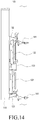
- a multi-band antenna apparatus having at least one size of 4ft, 7ft, and 9ft and enabling two RRHs formed as a single body in an antenna housing providing a plurality of antenna modules (refer to Figs. 14 and 15 ).
- a multi-band antenna apparatus where when an RRH is mounted on a surface of an antenna housing, an antenna module and the RRH connected with the antenna module may make an electrical connection.
- Fig. 1 is an exploded side view illustrating a multi-band antenna apparatus according to an embodiment of the present invention.
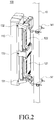
- Fig. 2 is an assembled perspective view illustrating a multi-band antenna apparatus according to an embodiment of the present invention.
- the multi-band antenna apparatus 100 includes an antenna housing 110 where antenna modules (not shown) having at least two or more frequency bands are mounted, a plurality of relays 120 formed as a single body in the antenna housing 110 and individually and detachably coupled to the antenna housing 110, and brackets 131, 132, 133, and 141 individually and detachably coupling the plurality of relays 120 to the antenna housing 110.
- the antenna modules mounted in the antenna housing 110 are, e.g., multi-band antennas of an antenna module covering a legacy 850MHz band, an antenna module covering a PCS band (the antenna module for 850MHz and the antenna module for PCS are collectively referred to as “third antenna modules” (not shown)), as well as an antenna module covering a 700MHz band (hereinafter, a “first antenna module” (not shown)), and an antenna module covering an advanced wireless service (AWS) band (hereinafter, a “second antenna module” (not shown)) for description purposes.
- the antenna modules 110 are multi-band antennas that may cover at least two frequency bands including antenna modules with bands recently offered, as well as antenna modules with existing service bands.
- the first antenna module, the second antenna module, and the third antenna modules all are together provided in one antenna housing 110.
- the relays are devices that are respectively connected with the antenna modules with frequency bands provided in the antenna housing 110 to perform communication with the antennas and a base station.
- the relays are devices that receive signals weakened between a base station in a communication system and a mobile communication terminal, amplify, or retransmit the signals, or normalize distorted waveforms, adjust the timing or reconfigure, and transmit the signals.
- the relays include a first relay connected with the first antenna module, a second relay connected with the second antenna module, and third relays (not shown) connected with the third antenna modules, where the third relays may be divided into a relay connected with the antenna module for 850MHz and a relay connected with the PCS antenna module.
- the third relays hereinafter, “third radio remote heads (RRHs") connected with the third antenna modules are installed on, e.g., outer walls 10 and 101 separately from the antenna housing 110 and are electrically connected with the first antenna module through cables.
- the first relay 120a (hereinafter, a "first RRH") connected with the first antenna module and the second relay 120b (hereinafter, a “second RRH”) connected with the second antenna module are provided to be formable on a surface of the antenna housing as a single body 133a (which may be referred to as a single-body type).
- the first RRH 121 and the second RRH 122 may be mounted to neighbor each other on a surface of the antenna housing 110 so that they may be individually and detachably coupled.
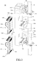
- Fig. 3 is a perspective view illustrating a multi-band antenna apparatus as viewed in a different direction, wherein a first RRH and a second RRH are separated, according to an embodiment of the present invention.
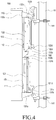
- Fig. 4 is an assembled side view illustrating a multi-band antenna apparatus according to an embodiment of the present invention.
- the connector portions 111 and 112 are provided to protrude from the rear surface of the antenna housing 110 to electrically connect a plurality of RRHs 120A and 120B provided as a single body in the antenna housing 110 to their respective antenna modules provided in the antenna housing 110.
- the connector portions 111 and 112 may include a first connector 111 and a second connector 112.
- the first connector 111 is positioned at a lower side of the rear surface of the antenna housing 110 and is provided to vertically protrude on the rear surface of the antenna housing 110. Further, the first connector 111 is a component that electrically connects the first RRH 121 with the first antenna module provided in the antenna housing 110. The first connector 111 is provided to be movable in the vertical direction at a predetermined distance from the rear surface of the antenna housing 110. Thus, if the first RRH 121 is connected to the rear surface of the antenna housing 110, the first connector 111 may be driven in at least one way of automatically, semi-automatically, or manually. For example, a snap on-type connector may be provided to enable a one-touch connection or disconnection.
- the first connector 111 may be electrically connected with the first RRH 121, specifically, a first connector terminal 151 positioned on the front surface of the first RRH 121.
- the second connector 112 is positioned on the rear surface of the antenna housing 110, spaced apart at a predetermined interval from an upper side of the first connector 111, and provided to vertically protrude from the rear surface of the antenna housing 110. Further, the second connector 112 is a component that electrically connects the second RRH 122 with the second antenna module provided in the antenna housing 110. The second connector 112 is provided to be movable in the vertical direction at a predetermined distance from the rear surface of the antenna housing 110. Thus, if the second RRH 122 is coupled to the rear surface of the antenna housing 110, the second connector 112 may be driven in at least one way of automatically, semi-automatically, or manually to vertically move in the protruding direction from the rear surface of the antenna housing 110.
- a snap on-type connector portion 151 may be provided to enable a one-touch connection or disconnection.
- the first connector 111 vertically moves in the protruding direction from the rear surface of the antenna housing 110, it may be electrically connected with the second RRH 122, specifically, a second connector terminal 152 positioned on the front surface of the second RRH 122.
- first RRH 121 and the second RRH 122 are mounted adjacent to each other in the direction of gravity on the rear surface of the antenna housing 110 according to an embodiment of the present invention.
- first connector 111 and the second connector 112 electrically connected with the first RRH 121 and the second RRH 122 arranged in the gravity direction on the rear surface of the antenna housing 110 may be positioned adjacent to each other in the gravity direction.
- the first connector 111 and the second connector 112 may be formed to protrude at a predetermined distance not interfering with a slide of the first RRH 121 and the second RRH 122 in a direction parallel with the rear surface of the antenna housing 110. Further, the first connector 111 and the second connector 112 are driven in at least one way of automatically, semi-automatically, or manually along the protruding direction from the rear surface of the antenna housing 110. Thus, if the first RRH 121 and the second RRH 122 are mounted on the rear surface of the antenna housing 110, the first connector 111 may be electrically connected with the first connector terminal 151, and the first connector 111 may be electrically connected with the second connector terminal 152.
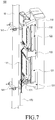
- Fig. 5 is a perspective view illustrating a multi-band antenna apparatus, wherein a front surface of a first RRH or a second RRH is shown, according to an embodiment of the present invention.
- Fig. 6 is a perspective view illustrating a multi-band antenna apparatus, wherein a rear surface of a first RRH or a second RRH is shown, according to an embodiment of the present invention.
- a plurality of RRHs 120A and 120B may be mounted adjacent to each other as a single body on the rear surface of the antenna housing 110.
- the RRHs 120A and 120B may include the first RRH 121, the second RRH 122, and the third RRHs (not shown), and among them, at least two or more RRHs (e.g., the first RRH 121 and the second RRH 122 in the instant embodiment for description purposes) may be mounted as a single body on the rear surface of the antenna housing 110.
- first RRH 121 and the second RRH 122 detachably provided as a single body in the antenna housing 110 are described below, since the first RRH 121 and the second RRH 122 have similar configurations and shapes except for their positions mounted, a description of the configuration of one RRH may apply to the other RRH, and thus, differences in the position mounted are described below.
- the first RRH 121 (whose description also applies to the second RRH 122) may slide along guiding brackets 131, 132, and 133 (which are described below) positioned at a lower side of the rear surface of the antenna housing 110, having a space for mounting the first RRH 121, and provided to attach or detach the first RRH 121, and the first RRH 121 may be provided as a single body on the rear surface of the antenna housing 110.
- a surface (hereinafter, a "front surface") of the first RRH 121 where the first RRH 121 faces the antenna housing 110 has the first connector terminal 151 protruding therefrom and connecting with the first connector 111.
- the first connector 111 and the first connector terminal 151 face each other, and they respectively protrude from the rear surface of the antenna housing 110 and the first RRH 121. Further, the first connector 111 and the first connector terminal 151 are protruded not to cause interference between the rear surface of the antenna housing 110 and the front surface of the first RRH 121 when the first RRH 121 slides while spacing itself apart from the rear surface of the antenna housing 110 at a predetermined interval.
- a first heat-dissipation fin member 121c may be provided on the surface of the first RRH 121 to effectively dissipate heat generated from internal components of the first RRH 121.
- the first heat-dissipation fin member 121c may be positioned on the front surface of the first RRH 121 and the rear surface of the second RRH 122.
- the position of the first heat-dissipation fin member 121c is not limited thereto.
- the first heat-dissipation fin member 121c may be positioned along a side edge of the first RRH 121.
- the first RRH 121 is provided as a single body in the antenna housing 110 and is detachably and separately provided in the antenna housing 110.
- the first RRH 121 is provided as a single body in the antenna housing 110.
- the first RRH 121 is provided to slide in or out of a first mount space S1 (which is described below) of the guiding brackets 131, 132, and 133 to be attached or detached from the antenna housing 110.
- the first RRH 121 is a component provided to be supported on the rear surface of the antenna housing 110 through the guiding brackets 131, 132, and 133 while left in the first mount spaces S1 and S1.
- the guiding parts 121b and 122a described below may be provided on the top and bottom of the first RRH 121 of the surrounding edge of the first RRH 121.
- the guiding parts 121b and 122b provided on the top and bottom of the first RRH 121 are described as provided as first sliding members 121b among the guiding parts 121b, 122b, 131b, 132b, 133b, and 133c, for example.
- the first sliding members 121b may be first sliding protrusions 121b projecting from the top and bottom of the first RRH 121.
- the first sliding protrusions 121b may be inserted into the first guiding members 131b and 133b among the guiding parts 121b, 122b, 131b, 132b, 133b, and 133c described below (where, the guiding members 131b, 132b, 133b, and 133c are formed as guiding rails) and slide along the first guiding members 131b and 133b to attach or detach on the guiding brackets 131, 132, and 133 and to be supported in the first mount space S1.
- the guiding parts 122a, 122b, 131b, 132b, 133b, and 133c are described below in detail.
- the first RRH 121 may be provided with a first handle 121a for comfortable attaching or detaching or user convenience.
- the first RRH 121 is configured to slide or attach/detach in a vertical direction of the gravity direction (which refers to a direction perpendicular to the protruding direction of the first connector 111), i.e., through a side surface of the guiding brackets 131, 132, and 133, in the instant embodiment, the first handle 121a may be placed on the side surface of the first RRH 121.
- a first photoelectric composite cable terminal 121d may be provided on the rear surface of the first RRH 121. That is, the first photoelectric composite connector terminal 121d may be provided to allow for a connection of an external photoelectric composite cable (hereinafter, a "first cable 171") having a power source terminal and an optical terminal provided in a single cable.
- a first photoelectric composite connector terminal 122d e.g., a hybrid connector terminal, may be provided on the rear surface of the second RRH 122.
- the first photoelectric composite connector terminal 122d may be provided to allow for a connection of an external photoelectric composite cable (hereinafter, a "second cable 172") having a power source terminal and an optical terminal provided in a single cable.
- a second cable 172 an external photoelectric composite cable having a power source terminal and an optical terminal provided in a single cable.
- Fig. 7 is a view illustrating a multi-band antenna apparatus as viewed in a different direction, wherein an external cable is connected with a first RRH and a second RRH, according to an embodiment of the present invention.
- the external cable 170 may have both the first cable 171 and the second cable 172 in a single cable body 133a.
- the first cable 171 and the second cable 172 in the single body 133a may be branched near the first RRH 121.
- the first cable 171 is electrically connected with the first photoelectric composite connector terminal 121d provided on the rear surface of the first RRH 121
- the second cable 172 may be electrically connected with the first photoelectric composite connector terminal 122d provided on the rear surface of the second RRH 122.
- the second RRH 122 is similar in structure and shape to the first RRH 121 (refer to Figs. 5 and 6 ).
- the first RRH 121 is provided at a lower side on the rear surface of the antenna housing 110
- the second RRH 122 is mounted at an upper side above the first RRH 121 on the rear surface of the antenna housing 110.
- the second RRH 122 and the first RRH 121 under the second RRH 122 may be mounted neighboring each other along the gravity direction.
- the second RRH 122 (whose description applies likewise to the second RRH 122) is positioned under the first RRH 121 at a lower side on the rear surface of the antenna housing 110. Accordingly, the second RRH 122 may be slid along the guiding brackets 131, 132, and 133 (described below) provided to attach or detach the second RRH 122 in the space for mounting the second RRH 122 positioned below the space for mounting the first RRH 121 to be provided as a single body on the rear surface of the antenna housing 110.
- a surface (hereinafter, a "front surface") of the second RRH 122 where the second RRH 122 faces the antenna housing 110 has the second connector terminal 152 protruding therefrom and connecting with the second connector 112.
- the second connector 112 and the second connector terminal 152 face each other, and they respectively protrude from the rear surface of the antenna housing 110 and the second RRH 122. Further, the second connector 112 and the second connector terminal 152 are protruded not to cause interference between the rear surface of the antenna housing 110 and the front surface of the second RRH 122 when the second RRH 122 slides while spacing itself apart form the rear surface of the antenna housing 110 at a predetermined interval.
- a second heat-dissipation fin member 122c may be provided on the surface of the second RRH 122 to effectively dissipate heat generated from internal components of the second RRH 122.
- the second heat-dissipation fin member 122c may be positioned on the front surface of the first RRH 121 and the rear surface of the second RRH 122.
- the position of the second heat-dissipation fin member 122c is not limited thereto.
- the second heat-dissipation fin member 122c may be positioned along a side edge of the second RRH 122.
- the guiding parts 122a, 122b, 131b, 132b, 133b, and 133c described below may be provided on the top and bottom of the second RRH 122 of the surrounding edge of the second RRH 122.
- the guiding parts 122a, 122b, 131b, 132b, 133b, and 133c provided on the top and bottom of the second RRH 122 are described as provided as second sliding members 122b among the guiding parts 121b, 122b, 131b, 132b, 133b, and 133c, for example.
- the second sliding members 122b may be second sliding protrusions 122b projecting from the top and bottom of the first RRH 121.
- the second sliding protrusions 122b may be inserted into the second guiding members 132b and 133c among the guiding parts 121b, 122b, 131b, 132b, 133b, and 133c described below (where, the guiding members 131b, 132b, 133b, and 133c are formed as guiding rails) and slide along the second guiding members 132b and 133c to attach or detach on the guiding brackets 131, 132, and 133 and to be supported in the second mount space S2.
- the guiding parts 122a, 122b, 131b, 132b, 133b, and 133c are described below in detail.
- the second RRH 122 is provided as a single body in the antenna housing 110 and is detachably and separately provided in the antenna housing 110.
- the second RRH 122 is provided as a single body in the antenna housing 110 and is slid in or out of the second mount space S2 (which is described below) of the guiding brackets 131, 132, and 133 to attach or detach at an upper side (as compared with the space for mounting the first RRH 121) of the antenna housing 110.
- the second RRH 122 may be provided to be supported on the rear surface of the antenna housing 110 through the guiding brackets 131, 132, and 133 while left in the second mount spaces S2 and S2.
- the second RRH 122 may be provided to be supported at an upper side of the first RRH 121 detachably mounted on the rear surface of the antenna. Further, the second RRH 122 may have a second handle 122a for easier attaching or detaching and user convenience.
- the second handle 122a may be installed on the side surface of the second RRH 122 considering the sliding direction of the second RRH 122 for attaching and detaching as the first handle 121a is.
- Fig. 8 is a perspective view illustrating a multi-band antenna apparatus according to an embodiment of the present invention.
- the multi-band antenna apparatus 100 may have brackets 131, 132, 133, and 141 fastening the antenna housing 110 to, e.g., the outer wall 10 and provided to attach or detach and support the first RRH 121 and the second RRH 122 as a single body.
- the brackets 131, 132, 133, and 141 may include brackets 141 for fastening and brackets 131, 132, and 133 for guiding.
- the fastening brackets 141 are provided as a first fastening bracket 141 and a second fastening bracket 141 that are coupled at an upper and lower side of the rear surface of the antenna housing 110 and fasten to the outer wall 10, and they are components for fastening the antenna housing 110 to the outer wall 10. According to an embodiment of the present invention, described is an example in which the fastening brackets 141 are coupled through connection with the guiding brackets 131, 132, and 133 described below and coupled to the rear surface of the antenna housing 110.
- the fastening brackets 141 may be provided at an upper and lower side of the antenna housing 110 and fastened to, e.g., the outer wall 10, and the guiding brackets 131, 132, and 133 may be provided between the fastening brackets 141.
- the fastening brackets 141 and the guiding brackets 131, 132, and 133 may be provided at an upper and lower side of the antenna housing 110 and fastened to, e.g., the outer wall 10
- the guiding brackets 131, 132, and 133 may be provided between the fastening brackets 141.
- Fig. 9 is a view illustrating a bracket for guiding provided in a rear surface of an antenna housing in a multi-band antenna apparatus according to an embodiment of the present invention.
- the guiding brackets 131, 132, and 133 are provided on the rear surface of the antenna housing 110 to attach, detach, and support the first RRH 121 and the second RRH 122 on the rear surface of the antenna housing 110. Further, the guiding brackets 131, 132, and 133 form a first mount space S1 and a second mount space S2 allowing the first RRH 121 and the second RRH 122 to be mounted on the rear surface of the antenna housing 110.
- the guiding brackets 131, 132, and 133 may include a first bracket 131 and a second bracket 132 provided at an upper and lower side of the antenna housing 110 and a third bracket 133 positioned between the first bracket 131 and the second bracket 132.
- the mounted position and overall structure of the first bracket 131, second bracket 132, and third bracket 133 are first described.
- the first mount space S1 for mounting the first RRH 121 is formed between the first bracket 131 and the third bracket 133, and the lower and upper portions of the first RRH 121 are provided to be seated, attached, or detached on the first bracket 131 and the third bracket 133, respectively.
- a pair of first guiding members 131b and 133b may be provided on opposite surfaces of the first bracket 131 and the third bracket 133.
- the second mount space S2 is formed between the second bracket 132 and the third bracket 133 to mount the second RRH 122, and the upper and lower portions of the second RRH 122 are provided to be seated, attached, or detached on the second bracket 132 and the third bracket 133.
- a pair of second guiding members 132b and 133c may be provided on opposite surfaces of the second bracket 132 and the third bracket 133.
- Fig. 10 is an expanded view illustrating a first bracket with a cover removed in a multi-band antenna apparatus according to an embodiment of the present invention.
- the first bracket is specifically a component that is positioned at the lowermost side of the antenna housing among the three brackets.
- the first bracket 131 may include a first supporting plate 131a and a first lower guiding rail 131b of a pair of first guiding members 131b and 133b.
- the first supporting plate 131a is a component that is provided to support a lower portion of the first RRH 121 and mounted in a direction perpendicular to the gravity on the rear surface of the antenna housing 110.
- Th first lower guiding rail 131b shaped as the letter "U” is provided on an upper surface of the first supporting plate 131a.
- the first lower guiding rail 131b is provided as a single body in the first supporting plate 131a.
- the term "single body” denotes components with two or more functions being constituted of one material without, e.g., a combined surface or components of the same or two different materials being combined together into one.
- first supporting plate 131a and the U-shaped first lower guiding rail 131b may form their shape through one material, or the same or two different materials may be combined together into a single component.
- the first bracket 131 is positioned at a lowermost side of the antenna housing 110 and is connected with the fixing bracket 141 positioned at a lower side to support the antenna housing 110 to the outer wall 10.
- the first bracket 131 may be positioned separately from the underneath fixing bracket 141.
- a through hole H1 is formed to be spaced apart at a predetermined interval from the antenna housing 110 in the first bracket 131, specifically between both ends of the first supporting plate 131a. This is provided to allow external air to be introduced into a lower portion of the first RRH 121 to be able to generate heat.
- the first bracket 131 may further include a cover 131c covering both side surfaces of the first bracket 131, e.g., in an aesthetic point of view.
- Fig. 11 is an expanded view illustrating a second bracket in a multi-band antenna apparatus according to an embodiment of the present invention.
- the second bracket 132 is a component positioned at an uppermost side of the antenna housing 110 among the three brackets 131, 132, 133, and 141.
- the second bracket 132 may include a second supporting plate 132a and a second upper guiding rail 132b of a pair of second guiding members 132b and 133c.
- the second supporting plate 132a is a component that is provided to support an upper portion of the second RRH 122 and mounted in a direction perpendicular to the gravity on the upper surface of the antenna housing 110.
- Th second lower guiding rail 132b shaped as the letter "U" is provided on a lower surface of the second supporting plate 132a.
- the second upper guiding rail 132b is provided as a single body in the second supporting plate 132a.
- the term “single body” has been described above, and its description applies here.
- the second supporting plate 132a and the U-shaped second upper guiding rail 132b may form their shape through one material, or the same or two different materials may be combined together into a single component.
- the second bracket 132 is positioned at an uppermost side of the antenna housing 110 and is connected with the fixing bracket 141 positioned at an upper side to support the antenna housing 110 to the outer wall 10.
- the second bracket 132 may be positioned separately from the underneath fixing bracket 141.
- a through hole H2 is formed to be spaced apart at a predetermined interval from the antenna housing 110 in the second bracket 132, specifically between both ends of the second supporting plate 132a. This is provided to discharge air introduced through a through hole H3 formed in an upper surface of the third bracket 133 described below and heated up while passing through the second RRH 122 to an upper portion.
- the second bracket 132 may further include a cover 132c covering both side surfaces of the first bracket 131, e.g., in an aesthetic point of view.
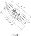
- Fig. 12 is an expanded view illustrating a third bracket in a multi-band antenna apparatus according to an embodiment of the present invention.
- Fig. 13 is an expanded view illustrating a third bracket having a cover unit mounted thereon in a multi-band antenna apparatus according to an embodiment of the present invention.
- the third bracket 133 is provided to support a lower portion of the first RRH 121 and an upper portion of the second RRH 122 while forming a space where an upper portion of the air outlet 12 is spaced apart from a lower portion of the second RRH 122.
- the third bracket 133 may include a body 133a forming an empty space S3, a first upper guiding rail 133b positioned in a lower surface of the body 133a, and a second lower guiding rail 133c positioned in an upper surface of the body 133a.
- the upper and lower surfaces of the body 133a form a through hole H3 allowing for penetration along with the empty space S3 except for the surface where the first upper guiding rail 133b and the second lower guiding rail 133c may be mounted.
- the through hole H3 formed in the lower surface of the body 133a is provided to allow heat generated from the first RRH 121 to be dissipated through the upper portion of the first RRH 121.
- the through hole H3 formed in the upper surface of the body 133a is provided allowing external air to be introduced into the second RRH 122 to generate heat.
- the third bracket 133 further includes a cover 133d to cover, e.g., the empty space S3.
- the cover 133d is provided for better outer look, and whether the cover 133d is provided to the third bracket 133 may be varied or altered.
- a shielding plate 180 (also referred to as a baffle) is provided in the empty space S3 of the body 133a.
- the shielding plate 180 is provided to be inclined from an upper outer edge of the body 133a to a lower internal edge thereof.
- the shielding plate 180 is provided to prevent high-temperature air discharged from the upper side of the first RRH 121 from flowing in the second RRH 122 and to allow external air to flow in the lower side of the second RRH 122.
- the RRHs 121 and 122 are mounted to neighbor each other in the rear surface of the antenna housing 110 by preventing high-temperature air discharged from the upper side of the first RRH 121 from flowing in the second RRH 122.
- first heat dissipation fin members 121c are provided on the exposed rear surfaces to be externally exposed, the plurality of RRHs mounted as a single body in the antenna housing 110 may enjoy increased heat-dissipation efficiency.
- the guiding brackets 131, 132, and 133 have guiding parts 122a, 122b, 131b, 132b, 133b, and 133c.
- the guiding parts 122a, 122b, 131b, 132b, 133b, and 133c may include sliding members 121b and 122b and guiding members 131b, 132b, 133b, and 133c (refer to Figs. 10 to 13 ).
- the sliding members 121b and 122b may include a first sliding member 121b and a second sliding member 122b.
- the first sliding member 121b is provided to protrude from each of the top and bottom of the first RRH 121 and is formed of a first sliding protrusion 121b.
- the first sliding protrusion 121b is seated on the above-described first guiding members 131b and 133b, specifically, the first upper guiding rail 133b and the first lower guiding rail 131b and is provided to be attached or detached from the first mount space S1 while sliding along the first upper guiding rail 133b and the first lower guiding rail 131b.
- the second sliding member 122b is provided to protrude from each of the top and bottom of the second RRH 122 and is formed of a second sliding protrusion 122b.
- the second sliding protrusion 122b is seated on the above-described second guiding members 132b and 133c, specifically, the second upper guiding rail 132b and the second lower guiding rail 133c and is provided to be attached or detached from the second mount space S2 while sliding along the second upper guiding rail 132b and the second lower guiding rail 133c.
- the guiding members 131b, 132b, 133b, and 133c have been described above together with the first bracket 131, the second bracket 132, and the third bracket 133.
- the guiding members 131b, 132b, 133b, and 133c may include first guiding members 131b and 133b and second guiding members 132b and 133c.
- the first guiding members 131b and 133b are provided to face each other with the first mount space S1 positioned therebetween, seat the first RRH 121 thereon, and guide the first RRH 121 to slide in the first mount space S1.
- the first guiding members 131b and 133b may include a first lower guiding rail 131b provided in an upper surface of the first bracket 131 and a first upper guiding rail 133b provided in a lower surface of the body 133a of the third bracket 133.
- the first upper guiding rail 133b and the first lower guiding rail 131b each are shaped as the letter "U" and mounted to face each other.
- the first sliding protrusion 121b is seated on each of the first upper guiding rail 133b and the first lower guiding rail 131b, and the first upper guiding rail 133b and the first lower guiding rail 131b guide a slide of the first sliding protrusion 121b.
- the second guiding members 132b and 133c are provided to face each other with the second mount space S2 positioned therebetween, seat the second RRH 122 thereon, and guide the first RRH 122 to slide in the second mount space S1.
- the second guiding members 132b and 133c may include a second upper guiding rail 132b provided in a lower surface of the second bracket 132 and a second lower guiding rail 133c provided in an upper surface of the body 133a of the third bracket 133.
- the second upper guiding rail 132b and the second lower guiding rail 133c each are shaped as the letter "U" and mounted to face each other.
- the second sliding protrusion 122b is seated on each of the second upper guiding rail 132b and the second lower guiding rail 133c, and the second upper guiding rail 132b and the second lower guiding rail 133c guide a slide of the second sliding protrusion 122b.
- the first RRH 121 and the second RRH 122 may separately be detached or replaced from the antenna housing 110 with a plurality of antenna modules, with the antenna housing 110 fastened to the outer wall 10. That is, as described above, the fixing brackets 141 positioned at an upper and lower side of the antenna housing 110 are fastened to the outer wall 10.
- the first mount space S1 and the second mount space S2 where a plurality of compact RRHs 121 and 122 are mounted to neighbor each other in parallel along the gravity direction by the guiding brackets 131, 132, and 133 are formed between the upper fastening bracket 141 and the lower fastening bracket 141 on the rear surface of the antenna housing 110.
- the first RRH 121 As the first sliding protrusions 121b on the upper and lower portion of the first RRH 121 are respectively seated and slid on the first upper guiding rail 133b and the first lower guiding rail 131b, the first RRH 121 is seated in the first mount space S1.
- the first handle 121a of the first RRH 121 seated in the first mount space S1 is pulled, the upper and lower first sliding protrusions 121b seated on the first upper guiding rail 133b and the first lower guiding rail 131b are slid along the first upper guiding rail 133b and the first lower guiding rail 131b and are thus escaped from the first mount space S 1.
- the second RRH 122 may be attached or detached from the second mount space S2 separately from the first RRH 121 attached or detached. That is, as the second sliding protrusions 122b on the upper and lower portion of the second RRH 122 are respectively seated and slid on the second upper guiding rail 132b and the second lower guiding rail 133c, the second RRH 122 is seated in the second mount space S2.
- the second RRH 122 may be attached or detached from the second mount space S2 separately from the first RRH 121 attached or detached, only one of the first RRH 121 or the second RRH 122 may be replaced, and the antenna modules other than the antenna module connected with the replaced RRH may be driven so that services corresponding to the antenna modules other than the one connected with the replaced RRH may remain in availability.
- heat-dissipation efficiency between the RRHs may be maintained or enhanced.
- the antenna apparatus has a 4ft size as an example.
- the present invention is not limited thereto.
- the antenna housing may be sized to be 7ft or 9ft, and various changes or modifications may be made to the size.
- Fig. 14 is a view illustrating an example in which an antenna housing is sized to be 7ft in a multi-band antenna apparatus according to an embodiment of the present invention.
- Fig. 15 is a view illustrating an example in which an antenna housing is sized to be 9ft in a multi-band antenna apparatus according to an embodiment of the present invention.
- Figs. 14 and 15 examples in which two RRHs are mounted depending on the size of the antenna housing 110 and embodiments of fastening structures may be shown, and their description is the same as what has been described above, and the above description applies thereto.
Landscapes
- Engineering & Computer Science (AREA)
- Computer Networks & Wireless Communication (AREA)
- Support Of Aerials (AREA)
- Telephone Set Structure (AREA)
Abstract
Description
- The present invention relates to an antenna apparatus, and particularly, to a multi-band antenna apparatus having a plurality of radio remote heads (RRHs) and enabling an antenna to connect with a RRH.
- As wireless mobile communication services are commonplace, antenna apparatuses are spreading, which may offer services in a more stabilized manner. In particular, wireless mobile communication services, which had been provided via 2nd generation (2G) and 3G allowing only for voice calls, now adopt 4G mobile communication techniques based on long term evolution (LTE) enabling communication of various data signals. Antenna apparatuses for such 4G mobile communication and legacy antenna apparatuses are installed in a limited space. That is, 700MHz, 850MHz, PCS, and advanced wireless service (AWS) band antennas and their respective corresponding radio remote heads ('RRH") are installed in a single limited space.
- Antenna apparatuses with such structure end up with the result that at least four antennas, as well as their respective corresponding RRHs are installed in a limited space. This leads to spatial limitations and increased costs. Further, recommended sizes of antennas in an antenna apparatus are 4ft, 6ft, or 8ft, and in case multiple antennas are equipped in one antenna housing, the RRHs respectively corresponding to the antenna frequencies suffer from an insufficient installation space.
- Further, equipping multiple antennas in one antenna housing results in an insufficient space for placing the RRHs adjacent to the antenna housing.
- In case a plurality of antennas are mounted in a single housing and a plurality of RRHs are placed in one RRH housing, the antennas corresponding to the RRHs in the RRH housing, as well as the corresponding frequency antennas might be not used upon exchanging RRHs.
- Thus, according to an embodiment of the present invention, there is provided a multi-band antenna apparatus allowing multiple antennas to be equipped in a single housing.
- Further, there is provided a multi-band antenna apparatus that may equip at least two or more RRHs respectively corresponding to frequencies in an antenna housing with a plurality of antennas, is provided to separately each RRH, and enables simple exchange of the RRHs.
- To the end, according to an embodiment of the present invention, a multi-band antenna apparatus may comprise an antenna housing mounting antenna modules with two or more frequency bands, a plurality of relays detachably coupled to the antenna housing as the relays slide, connector portions respectively connected with the plurality of relays and protruding from the antenna housing, and brackets fastening the antenna housing to an outer wall and individually and detachably coupling the plurality of relays to the antenna housing.
- According to an embodiment of the present invention, the multi-band antenna apparatus described above benefits installation of multiple antennas, e.g., 700MHz, 850MHz, PCS, and AWS band antennas, in one antenna housing.
- Further, the RRHs respectively connected with the antennas may be provided at an outside of the antenna housing. In particular, among the RRHs, RRHs for 3G or 4G (e.g., RRHs connected with antennas for 700MHz and AWS) may be mounted adjacent to the antenna housing, allowing at least two or more RRHs to be formed in the antenna housing as a single body.
- Further to single-body formation of the RRHs in the antenna housing, each RRH may be detachably and separately provided in the antenna housing, enabling simple exchange of RRHs upon malfunctioning or failure.
- Further, antennas except for only antennas corresponding to malfunctioning or exchanged RRHs may be normally operated, and thus, services corresponding to the normally working antennas are still in availability.
-
-
Fig. 1 is an exploded side view illustrating a multi-band antenna apparatus according to an embodiment of the present invention; -
Fig. 2 is an assembled perspective view illustrating a multi-band antenna apparatus according to an embodiment of the present invention; -
Fig. 3 is a perspective view illustrating a multi-band antenna apparatus as viewed in a different direction, wherein a first RRH and a second RRH are separated, according to an embodiment of the present invention; -
Fig. 4 is an assembled side view illustrating a multi-band antenna apparatus according to an embodiment of the present invention; -
Fig. 5 is a perspective view illustrating a multi-band antenna apparatus, wherein a front surface of a first RRH or a second RRH is shown, according to an embodiment of the present invention; -
Fig. 6 is a perspective view illustrating a multi-band antenna apparatus, wherein a rear surface of a first RRH or a second RRH is shown, according to an embodiment of the present invention; -
Fig. 7 is a view illustrating a multi-band antenna apparatus as viewed in a different direction, wherein an external cable is connected with a first RRH and a second RRH, according to an embodiment of the present invention; -
Fig. 8 is a perspective view illustrating a multi-band antenna apparatus according to an embodiment of the present invention; -
Fig. 9 is a view illustrating a bracket for guiding provided in a rear surface of an antenna housing in a multi-band antenna apparatus according to an embodiment of the present invention; -
Fig. 10 is an expanded view illustrating a first bracket with a cover removed in a multi-band antenna apparatus according to an embodiment of the present invention; -
Fig. 11 is an expanded view illustrating a second bracket in a multi-band antenna apparatus according to an embodiment of the present invention; -
Fig. 12 is an expanded view illustrating a third bracket in a multi-band antenna apparatus according to an embodiment of the present invention; -
Fig. 13 is an expanded view illustrating a third bracket having a cover unit mounted thereon in a multi-band antenna apparatus according to an embodiment of the present invention; -
Fig. 14 is a view illustrating an example in which an antenna housing is sized to be 7ft in a multi-band antenna apparatus according to an embodiment of the present invention; and -
Fig. 15 is a view illustrating an example in which an antenna housing is sized to be 9ft in a multi-band antenna apparatus according to an embodiment of the present invention. - Various changes may be made to the present invention, and the present invention may come with a diversity of embodiments. Some embodiments of the present invention are shown and described in connection with the drawings. However, it should be appreciated that the present invention is not limited to the embodiments, and all changes and/or equivalents or replacements thereto also belong to the scope of the present invention.
- The terms coming with ordinal numbers such as 'first' and 'second' may be used to denote various components, but the components are not limited by the terms. The terms are used only to distinguish one component from another. For example, a first component may be denoted a second component, and vice versa without departing from the scope of the present invention. The term "and/or" may denote a combination(s) of a plurality of related items as listed or any of the items.
- The terms "front," "rear surface," "upper surface," and "lower surface" are relative ones that may be varied depending on directions in which the figures are viewed, and may be replaced with ordinal numbers such as "first" and "second." The order denoted by the ordinal numbers, first and second, may be varied as necessary.
- The terms as used herein are provided merely to describe some embodiments thereof, but not to limit the present invention. It is to be understood that the singular forms "a," "an," and "the" include plural references unless the context clearly dictates otherwise. It will be further understood that the terms "comprise" and/or "have," when used in this specification, specify the presence of stated features, integers, steps, operations, elements, and/or components, but do not preclude the presence or addition of one or more other features, integers, steps, operations, elements, components, and/or groups thereof.
- Unless otherwise defined, all terms including technical and scientific terms used herein have the same meaning as commonly understood by one of ordinary skill in the art to which the embodiments of the present invention belong. It will be further understood that terms, such as those defined in commonly used dictionaries, should be interpreted as having a meaning that is consistent with their meaning in the context of the relevant art and will not be interpreted in an idealized or overly formal sense unless expressly so defined herein.
- For description purposes, a multi-band antenna apparatus according to an embodiment of the present invention has multi-band antennas having at least two or more frequency bands to cover such two or more frequency bands in one antenna housing. Specifically, there is disclosed a multi-band antenna apparatus where antennas with legacy PCS, 2G mobile communication service, 3G, and 4G mobile communication service bands, from a frequency band perspective, 700MHz, 850MHz, PCS, or advanced wireless service (AWS) band antennas, are equipped in one housing.
- Further, there is provided a multi-band antenna apparatus where, among four RRHs respectively connected with the frequency band antennas to receive their respective antenna signals and signals from a base station, specifically, a RRH for 700MHz (hereinafter, "first RRH"), a RRH for AWS (hereinafter, "second RRH"), a RRH for 850MHz (hereinafter, "third RRH"), and a RRH for PCS (hereinafter, "fourth RRH"), at least two or more RRHs are provided to be formed in the antenna housing as a single body and they are individually attached or detached from the antenna housing.
- Further, a multi-band antenna apparatus is disclosed where when a plurality of RRHs mounted in an antenna housing as a single body, they may be connected with their respective corresponding antennas.
- Further, there is disclosed an antenna apparatus having a plurality of RRHs in an antenna housing as a single body and enabling RRHs to be separately attached or detached from the antenna housing for replacing or repairing each RRH so that antennas except for the antennas connected with replaced RRHs may be put in continuous use and service.
- Further, according to an embodiment of the present invention, there is disclosed a multi-band antenna apparatus having at least one size of 4ft, 7ft, and 9ft and enabling two RRHs formed as a single body in an antenna housing providing a plurality of antenna modules (refer to
Figs. 14 and15 ). - Further, according to an embodiment of the present invention, there is disclosed a multi-band antenna apparatus where when an RRH is mounted on a surface of an antenna housing, an antenna module and the RRH connected with the antenna module may make an electrical connection.
-
Fig. 1 is an exploded side view illustrating a multi-band antenna apparatus according to an embodiment of the present invention.Fig. 2 is an assembled perspective view illustrating a multi-band antenna apparatus according to an embodiment of the present invention. - Referring to
Figs. 1 and2 , according to an embodiment of the present invention, themulti-band antenna apparatus 100 includes anantenna housing 110 where antenna modules (not shown) having at least two or more frequency bands are mounted, a plurality of relays 120 formed as a single body in theantenna housing 110 and individually and detachably coupled to theantenna housing 110, andbrackets antenna housing 110. Particularly in the instant embodiment, the antenna modules mounted in theantenna housing 110 are, e.g., multi-band antennas of an antenna module covering a legacy 850MHz band, an antenna module covering a PCS band (the antenna module for 850MHz and the antenna module for PCS are collectively referred to as "third antenna modules" (not shown)), as well as an antenna module covering a 700MHz band (hereinafter, a "first antenna module" (not shown)), and an antenna module covering an advanced wireless service (AWS) band (hereinafter, a "second antenna module" (not shown)) for description purposes. That is, theantenna modules 110 are multi-band antennas that may cover at least two frequency bands including antenna modules with bands recently offered, as well as antenna modules with existing service bands. As set forth above, the first antenna module, the second antenna module, and the third antenna modules all are together provided in oneantenna housing 110. The relays are devices that are respectively connected with the antenna modules with frequency bands provided in theantenna housing 110 to perform communication with the antennas and a base station. Specifically, the relays are devices that receive signals weakened between a base station in a communication system and a mobile communication terminal, amplify, or retransmit the signals, or normalize distorted waveforms, adjust the timing or reconfigure, and transmit the signals. According to this embodiment, the relays include a first relay connected with the first antenna module, a second relay connected with the second antenna module, and third relays (not shown) connected with the third antenna modules, where the third relays may be divided into a relay connected with the antenna module for 850MHz and a relay connected with the PCS antenna module. Although not shown, the third relays (hereinafter, "third radio remote heads (RRHs") connected with the third antenna modules are installed on, e.g.,outer walls 10 and 101 separately from theantenna housing 110 and are electrically connected with the first antenna module through cables. According to an embodiment of the present invention, the first relay 120a (hereinafter, a "first RRH") connected with the first antenna module and the second relay 120b (hereinafter, a "second RRH") connected with the second antenna module are provided to be formable on a surface of the antenna housing as asingle body 133a (which may be referred to as a single-body type). However, thefirst RRH 121 and thesecond RRH 122 may be mounted to neighbor each other on a surface of theantenna housing 110 so that they may be individually and detachably coupled. -
Fig. 3 is a perspective view illustrating a multi-band antenna apparatus as viewed in a different direction, wherein a first RRH and a second RRH are separated, according to an embodiment of the present invention.Fig. 4 is an assembled side view illustrating a multi-band antenna apparatus according to an embodiment of the present invention. - Referring to
Figs. 3 and4 , asmany connector portions 110 as the number of RRHs mounted on one surface (which corresponds to a "rear surface" in this embodiment and is hereinafter referred to as the rear surface) of theantenna housing 110 protrude from the rear surface of theantenna housing 110. That is, theconnector portions antenna housing 110 to electrically connect a plurality of RRHs 120A and 120B provided as a single body in theantenna housing 110 to their respective antenna modules provided in theantenna housing 110. Specifically, according to an embodiment of the present invention, theconnector portions first connector 111 and asecond connector 112. - The
first connector 111 is positioned at a lower side of the rear surface of theantenna housing 110 and is provided to vertically protrude on the rear surface of theantenna housing 110. Further, thefirst connector 111 is a component that electrically connects thefirst RRH 121 with the first antenna module provided in theantenna housing 110. Thefirst connector 111 is provided to be movable in the vertical direction at a predetermined distance from the rear surface of theantenna housing 110. Thus, if thefirst RRH 121 is connected to the rear surface of theantenna housing 110, thefirst connector 111 may be driven in at least one way of automatically, semi-automatically, or manually. For example, a snap on-type connector may be provided to enable a one-touch connection or disconnection. As thefirst connector 111 vertically moves in the protruding direction from the rear surface of theantenna housing 110, it may be electrically connected with thefirst RRH 121, specifically, afirst connector terminal 151 positioned on the front surface of thefirst RRH 121. - The
second connector 112 is positioned on the rear surface of theantenna housing 110, spaced apart at a predetermined interval from an upper side of thefirst connector 111, and provided to vertically protrude from the rear surface of theantenna housing 110. Further, thesecond connector 112 is a component that electrically connects thesecond RRH 122 with the second antenna module provided in theantenna housing 110. Thesecond connector 112 is provided to be movable in the vertical direction at a predetermined distance from the rear surface of theantenna housing 110. Thus, if thesecond RRH 122 is coupled to the rear surface of theantenna housing 110, thesecond connector 112 may be driven in at least one way of automatically, semi-automatically, or manually to vertically move in the protruding direction from the rear surface of theantenna housing 110. For example, a snap on-type connector portion 151 may be provided to enable a one-touch connection or disconnection. As thefirst connector 111 vertically moves in the protruding direction from the rear surface of theantenna housing 110, it may be electrically connected with thesecond RRH 122, specifically, asecond connector terminal 152 positioned on the front surface of thesecond RRH 122. - Described infra is an example in which the
first RRH 121 and thesecond RRH 122 are mounted adjacent to each other in the direction of gravity on the rear surface of theantenna housing 110 according to an embodiment of the present invention. Thus, thefirst connector 111 and thesecond connector 112 electrically connected with thefirst RRH 121 and thesecond RRH 122 arranged in the gravity direction on the rear surface of theantenna housing 110 may be positioned adjacent to each other in the gravity direction. - As described above, the
first connector 111 and thesecond connector 112 may be formed to protrude at a predetermined distance not interfering with a slide of thefirst RRH 121 and thesecond RRH 122 in a direction parallel with the rear surface of theantenna housing 110. Further, thefirst connector 111 and thesecond connector 112 are driven in at least one way of automatically, semi-automatically, or manually along the protruding direction from the rear surface of theantenna housing 110. Thus, if thefirst RRH 121 and thesecond RRH 122 are mounted on the rear surface of theantenna housing 110, thefirst connector 111 may be electrically connected with thefirst connector terminal 151, and thefirst connector 111 may be electrically connected with thesecond connector terminal 152. -
Fig. 5 is a perspective view illustrating a multi-band antenna apparatus, wherein a front surface of a first RRH or a second RRH is shown, according to an embodiment of the present invention.Fig. 6 is a perspective view illustrating a multi-band antenna apparatus, wherein a rear surface of a first RRH or a second RRH is shown, according to an embodiment of the present invention. - Referring to
Figs. 5 and6 , according to an embodiment of the present invention, a plurality of RRHs 120A and 120B may be mounted adjacent to each other as a single body on the rear surface of theantenna housing 110. According to an embodiment of the present invention, the RRHs 120A and 120B may include thefirst RRH 121, thesecond RRH 122, and the third RRHs (not shown), and among them, at least two or more RRHs (e.g., thefirst RRH 121 and thesecond RRH 122 in the instant embodiment for description purposes) may be mounted as a single body on the rear surface of theantenna housing 110. - Although the
first RRH 121 and thesecond RRH 122 detachably provided as a single body in theantenna housing 110 are described below, since thefirst RRH 121 and thesecond RRH 122 have similar configurations and shapes except for their positions mounted, a description of the configuration of one RRH may apply to the other RRH, and thus, differences in the position mounted are described below. - The first RRH 121 (whose description also applies to the second RRH 122) may slide along guiding
brackets antenna housing 110, having a space for mounting thefirst RRH 121, and provided to attach or detach thefirst RRH 121, and thefirst RRH 121 may be provided as a single body on the rear surface of theantenna housing 110. Although mentioned above, a surface (hereinafter, a "front surface") of thefirst RRH 121 where thefirst RRH 121 faces theantenna housing 110 has thefirst connector terminal 151 protruding therefrom and connecting with thefirst connector 111. Thefirst connector 111 and thefirst connector terminal 151 face each other, and they respectively protrude from the rear surface of theantenna housing 110 and thefirst RRH 121. Further, thefirst connector 111 and thefirst connector terminal 151 are protruded not to cause interference between the rear surface of theantenna housing 110 and the front surface of thefirst RRH 121 when thefirst RRH 121 slides while spacing itself apart from the rear surface of theantenna housing 110 at a predetermined interval. - A first heat-
dissipation fin member 121c may be provided on the surface of thefirst RRH 121 to effectively dissipate heat generated from internal components of thefirst RRH 121. According to an embodiment of the present invention, the first heat-dissipation fin member 121c may be positioned on the front surface of thefirst RRH 121 and the rear surface of thesecond RRH 122. However, the position of the first heat-dissipation fin member 121c is not limited thereto. For example, its position may be changed or altered as long as heat generated from internal components of thefirst RRH 121 is effectively dissipated--e.g., the first heat-dissipation fin member 121c may be positioned along a side edge of thefirst RRH 121. - As described supra, the
first RRH 121 is provided as a single body in theantenna housing 110 and is detachably and separately provided in theantenna housing 110. Thefirst RRH 121 is provided as a single body in theantenna housing 110. Thefirst RRH 121 is provided to slide in or out of a first mount space S1 (which is described below) of the guidingbrackets antenna housing 110. Thefirst RRH 121 is a component provided to be supported on the rear surface of theantenna housing 110 through the guidingbrackets - The guiding
parts first RRH 121 of the surrounding edge of thefirst RRH 121. In particular, according to an embodiment of the present invention, the guidingparts first RRH 121 are described as provided as first slidingmembers 121b among the guidingparts members 121b may be first slidingprotrusions 121b projecting from the top and bottom of thefirst RRH 121. Thus, the first slidingprotrusions 121b may be inserted into the first guidingmembers parts members members brackets parts - The
first RRH 121 may be provided with afirst handle 121a for comfortable attaching or detaching or user convenience. In particular, since thefirst RRH 121 is configured to slide or attach/detach in a vertical direction of the gravity direction (which refers to a direction perpendicular to the protruding direction of the first connector 111), i.e., through a side surface of the guidingbrackets first handle 121a may be placed on the side surface of thefirst RRH 121. - A first photoelectric
composite cable terminal 121d, e.g., a hybrid connector terminal, may be provided on the rear surface of thefirst RRH 121. That is, the first photoelectriccomposite connector terminal 121d may be provided to allow for a connection of an external photoelectric composite cable (hereinafter, a "first cable 171") having a power source terminal and an optical terminal provided in a single cable. Likewise, a first photoelectriccomposite connector terminal 122d, e.g., a hybrid connector terminal, may be provided on the rear surface of thesecond RRH 122. Similar to thefirst RRH 121 described above, the first photoelectriccomposite connector terminal 122d may be provided to allow for a connection of an external photoelectric composite cable (hereinafter, a "second cable 172") having a power source terminal and an optical terminal provided in a single cable. -
Fig. 7 is a view illustrating a multi-band antenna apparatus as viewed in a different direction, wherein an external cable is connected with a first RRH and a second RRH, according to an embodiment of the present invention. - Referring to
Fig. 7 , according to an embodiment of the present invention, theexternal cable 170 may have both thefirst cable 171 and thesecond cable 172 in asingle cable body 133a. Thefirst cable 171 and thesecond cable 172 in thesingle body 133a may be branched near thefirst RRH 121. Thus, thefirst cable 171 is electrically connected with the first photoelectriccomposite connector terminal 121d provided on the rear surface of thefirst RRH 121, and thesecond cable 172 may be electrically connected with the first photoelectriccomposite connector terminal 122d provided on the rear surface of thesecond RRH 122. - According to an embodiment of the present invention, as mentioned above, the
second RRH 122 is similar in structure and shape to the first RRH 121 (refer toFigs. 5 and6 ). However, thefirst RRH 121 is provided at a lower side on the rear surface of theantenna housing 110, and thesecond RRH 122 is mounted at an upper side above thefirst RRH 121 on the rear surface of theantenna housing 110. Accordingly, as viewed from the rear surface of theantenna housing 110, thesecond RRH 122 and thefirst RRH 121 under thesecond RRH 122 may be mounted neighboring each other along the gravity direction. - Specifically, the second RRH 122 (whose description applies likewise to the second RRH 122) is positioned under the
first RRH 121 at a lower side on the rear surface of theantenna housing 110. Accordingly, thesecond RRH 122 may be slid along the guidingbrackets second RRH 122 in the space for mounting thesecond RRH 122 positioned below the space for mounting thefirst RRH 121 to be provided as a single body on the rear surface of theantenna housing 110. Although mentioned above, a surface (hereinafter, a "front surface") of thesecond RRH 122 where thesecond RRH 122 faces theantenna housing 110 has thesecond connector terminal 152 protruding therefrom and connecting with thesecond connector 112. Thesecond connector 112 and thesecond connector terminal 152 face each other, and they respectively protrude from the rear surface of theantenna housing 110 and thesecond RRH 122. Further, thesecond connector 112 and thesecond connector terminal 152 are protruded not to cause interference between the rear surface of theantenna housing 110 and the front surface of thesecond RRH 122 when thesecond RRH 122 slides while spacing itself apart form the rear surface of theantenna housing 110 at a predetermined interval. - A second heat-
dissipation fin member 122c may be provided on the surface of thesecond RRH 122 to effectively dissipate heat generated from internal components of thesecond RRH 122. According to an embodiment of the present invention, the second heat-dissipation fin member 122c may be positioned on the front surface of thefirst RRH 121 and the rear surface of thesecond RRH 122. However, the position of the second heat-dissipation fin member 122c is not limited thereto. For example, its position may be changed or altered as long as heat generated from internal components of thesecond RRH 122 is effectively dissipated--e.g., the second heat-dissipation fin member 122c may be positioned along a side edge of thesecond RRH 122. - The guiding
parts second RRH 122 of the surrounding edge of thesecond RRH 122. In particular, according to an embodiment of the present invention, the guidingparts second RRH 122 are described as provided as second slidingmembers 122b among the guidingparts members 122b may be second slidingprotrusions 122b projecting from the top and bottom of thefirst RRH 121. Thus, the second slidingprotrusions 122b may be inserted into thesecond guiding members parts members second guiding members brackets parts - The
second RRH 122 is provided as a single body in theantenna housing 110 and is detachably and separately provided in theantenna housing 110. Thesecond RRH 122 is provided as a single body in theantenna housing 110 and is slid in or out of the second mount space S2 (which is described below) of the guidingbrackets antenna housing 110. Thesecond RRH 122 may be provided to be supported on the rear surface of theantenna housing 110 through the guidingbrackets second RRH 122 may be provided to be supported at an upper side of thefirst RRH 121 detachably mounted on the rear surface of the antenna. Further, thesecond RRH 122 may have asecond handle 122a for easier attaching or detaching and user convenience. Thesecond handle 122a may be installed on the side surface of thesecond RRH 122 considering the sliding direction of thesecond RRH 122 for attaching and detaching as thefirst handle 121a is. -
Fig. 8 is a perspective view illustrating a multi-band antenna apparatus according to an embodiment of the present invention. - Referring to
Fig. 8 (along withFig. 1 ), according to an embodiment of the present invention, themulti-band antenna apparatus 100 may havebrackets antenna housing 110 to, e.g., theouter wall 10 and provided to attach or detach and support thefirst RRH 121 and thesecond RRH 122 as a single body. - According to an embodiment of the present invention, the
brackets brackets 141 for fastening andbrackets - The
fastening brackets 141 are provided as afirst fastening bracket 141 and asecond fastening bracket 141 that are coupled at an upper and lower side of the rear surface of theantenna housing 110 and fasten to theouter wall 10, and they are components for fastening theantenna housing 110 to theouter wall 10. According to an embodiment of the present invention, described is an example in which thefastening brackets 141 are coupled through connection with the guidingbrackets antenna housing 110. However, as described below, in case the size of RRHs mounted is small as compared with the size of theantenna housing 110, thefastening brackets 141 may be provided at an upper and lower side of theantenna housing 110 and fastened to, e.g., theouter wall 10, and the guidingbrackets fastening brackets 141. As such, various changes or modifications may be made to the position of mounting thefastening brackets 141 and the guidingbrackets -
Fig. 9 is a view illustrating a bracket for guiding provided in a rear surface of an antenna housing in a multi-band antenna apparatus according to an embodiment of the present invention. - Referring to
Fig. 9 (along withFigs. 1 and2 ), the guidingbrackets antenna housing 110 to attach, detach, and support thefirst RRH 121 and thesecond RRH 122 on the rear surface of theantenna housing 110. Further, the guidingbrackets first RRH 121 and thesecond RRH 122 to be mounted on the rear surface of theantenna housing 110. The guidingbrackets first bracket 131 and asecond bracket 132 provided at an upper and lower side of theantenna housing 110 and athird bracket 133 positioned between thefirst bracket 131 and thesecond bracket 132. - The mounted position and overall structure of the
first bracket 131,second bracket 132, andthird bracket 133 are first described. The first mount space S1 for mounting thefirst RRH 121 is formed between thefirst bracket 131 and thethird bracket 133, and the lower and upper portions of thefirst RRH 121 are provided to be seated, attached, or detached on thefirst bracket 131 and thethird bracket 133, respectively. As described below, a pair of first guidingmembers first bracket 131 and thethird bracket 133. - The second mount space S2 is formed between the
second bracket 132 and thethird bracket 133 to mount thesecond RRH 122, and the upper and lower portions of thesecond RRH 122 are provided to be seated, attached, or detached on thesecond bracket 132 and thethird bracket 133. As described below, a pair of second guidingmembers second bracket 132 and thethird bracket 133. -
Fig. 10 is an expanded view illustrating a first bracket with a cover removed in a multi-band antenna apparatus according to an embodiment of the present invention. - Referring to
Fig. 10 , the first bracket is specifically a component that is positioned at the lowermost side of the antenna housing among the three brackets. Thefirst bracket 131 may include a first supportingplate 131a and a firstlower guiding rail 131b of a pair of first guidingmembers plate 131a is a component that is provided to support a lower portion of thefirst RRH 121 and mounted in a direction perpendicular to the gravity on the rear surface of theantenna housing 110. Th firstlower guiding rail 131b shaped as the letter "U" is provided on an upper surface of the first supportingplate 131a. The firstlower guiding rail 131b is provided as a single body in the first supportingplate 131a. Here, the term "single body" denotes components with two or more functions being constituted of one material without, e.g., a combined surface or components of the same or two different materials being combined together into one. - Accordingly, the first supporting
plate 131a and the U-shaped first lower guidingrail 131b may form their shape through one material, or the same or two different materials may be combined together into a single component. - According to an embodiment of the present invention, described is an example in which the
first bracket 131 is positioned at a lowermost side of theantenna housing 110 and is connected with the fixingbracket 141 positioned at a lower side to support theantenna housing 110 to theouter wall 10. However, as mentioned above, various changes or modifications may be made thereto depending on the size of theantenna housing 110--for example, thefirst bracket 131 may be positioned separately from the underneath fixingbracket 141. - Further, a through hole H1 is formed to be spaced apart at a predetermined interval from the
antenna housing 110 in thefirst bracket 131, specifically between both ends of the first supportingplate 131a. This is provided to allow external air to be introduced into a lower portion of thefirst RRH 121 to be able to generate heat. According to an embodiment of the present invention, thefirst bracket 131 may further include a cover 131c covering both side surfaces of thefirst bracket 131, e.g., in an aesthetic point of view. -
Fig. 11 is an expanded view illustrating a second bracket in a multi-band antenna apparatus according to an embodiment of the present invention. - Referring to
Fig. 11 , thesecond bracket 132 is a component positioned at an uppermost side of theantenna housing 110 among the threebrackets second bracket 132 may include a second supportingplate 132a and a second upper guidingrail 132b of a pair of second guidingmembers plate 132a is a component that is provided to support an upper portion of thesecond RRH 122 and mounted in a direction perpendicular to the gravity on the upper surface of theantenna housing 110. Th second lower guidingrail 132b shaped as the letter "U" is provided on a lower surface of the second supportingplate 132a. The secondupper guiding rail 132b is provided as a single body in the second supportingplate 132a. Here, the term "single body" has been described above, and its description applies here. The second supportingplate 132a and the U-shaped second upper guidingrail 132b may form their shape through one material, or the same or two different materials may be combined together into a single component. - According to an embodiment of the present invention, described is an example in which the
second bracket 132 is positioned at an uppermost side of theantenna housing 110 and is connected with the fixingbracket 141 positioned at an upper side to support theantenna housing 110 to theouter wall 10. However, as mentioned above, various changes or modifications may be made thereto depending on the size of theantenna housing 110--for example, thesecond bracket 132 may be positioned separately from the underneath fixingbracket 141. - Further, a through hole H2 is formed to be spaced apart at a predetermined interval from the
antenna housing 110 in thesecond bracket 132, specifically between both ends of the second supportingplate 132a. This is provided to discharge air introduced through a through hole H3 formed in an upper surface of thethird bracket 133 described below and heated up while passing through thesecond RRH 122 to an upper portion. According to an embodiment of the present invention, thesecond bracket 132 may further include a cover 132c covering both side surfaces of thefirst bracket 131, e.g., in an aesthetic point of view. -
Fig. 12 is an expanded view illustrating a third bracket in a multi-band antenna apparatus according to an embodiment of the present invention.Fig. 13 is an expanded view illustrating a third bracket having a cover unit mounted thereon in a multi-band antenna apparatus according to an embodiment of the present invention. - Referring to
Figs. 12 and13 , thethird bracket 133 is provided to support a lower portion of thefirst RRH 121 and an upper portion of thesecond RRH 122 while forming a space where an upper portion of the air outlet 12 is spaced apart from a lower portion of thesecond RRH 122. Specifically, thethird bracket 133 may include abody 133a forming an empty space S3, a first upper guidingrail 133b positioned in a lower surface of thebody 133a, and a second lower guidingrail 133c positioned in an upper surface of thebody 133a. - According to an embodiment of the present invention, the upper and lower surfaces of the
body 133a form a through hole H3 allowing for penetration along with the empty space S3 except for the surface where the first upper guidingrail 133b and the second lower guidingrail 133c may be mounted. Specifically, the through hole H3 formed in the lower surface of thebody 133a is provided to allow heat generated from thefirst RRH 121 to be dissipated through the upper portion of thefirst RRH 121. Further, the through hole H3 formed in the upper surface of thebody 133a is provided allowing external air to be introduced into thesecond RRH 122 to generate heat. - According to an embodiment of the present invention, described is an example in which the
third bracket 133 further includes acover 133d to cover, e.g., the empty space S3. Thecover 133d is provided for better outer look, and whether thecover 133d is provided to thethird bracket 133 may be varied or altered. - A shielding plate 180 (also referred to as a baffle) is provided in the empty space S3 of the
body 133a. The shieldingplate 180 is provided to be inclined from an upper outer edge of thebody 133a to a lower internal edge thereof. The shieldingplate 180 is provided to prevent high-temperature air discharged from the upper side of thefirst RRH 121 from flowing in thesecond RRH 122 and to allow external air to flow in the lower side of thesecond RRH 122. In particular, it is provided to present maximized heat-dissipation efficiency when theRRHs antenna housing 110 by preventing high-temperature air discharged from the upper side of thefirst RRH 121 from flowing in thesecond RRH 122. Further, as the rear surfaces of thefirst RRH 121 and thesecond RRH 122 are exposed externally, and first heatdissipation fin members 121c are provided on the exposed rear surfaces to be externally exposed, the plurality of RRHs mounted as a single body in theantenna housing 110 may enjoy increased heat-dissipation efficiency. - According to an embodiment of the present invention, the guiding
brackets parts parts members members Figs. 10 to 13 ). - The sliding
members member 121b and a second slidingmember 122b. - The first sliding
member 121b is provided to protrude from each of the top and bottom of thefirst RRH 121 and is formed of a first slidingprotrusion 121b. The first slidingprotrusion 121b is seated on the above-described first guidingmembers rail 133b and the firstlower guiding rail 131b and is provided to be attached or detached from the first mount space S1 while sliding along the first upper guidingrail 133b and the firstlower guiding rail 131b. - The second sliding
member 122b is provided to protrude from each of the top and bottom of thesecond RRH 122 and is formed of a second slidingprotrusion 122b. The second slidingprotrusion 122b is seated on the above-described second guidingmembers upper guiding rail 132b and the second lower guidingrail 133c and is provided to be attached or detached from the second mount space S2 while sliding along the secondupper guiding rail 132b and the second lower guidingrail 133c. - The guiding
members first bracket 131, thesecond bracket 132, and thethird bracket 133. Briefly, according to an embodiment of the present invention, the guidingmembers members members - The
first guiding members first RRH 121 thereon, and guide thefirst RRH 121 to slide in the first mount space S1. Thefirst guiding members lower guiding rail 131b provided in an upper surface of thefirst bracket 131 and a first upper guidingrail 133b provided in a lower surface of thebody 133a of thethird bracket 133. The first upper guidingrail 133b and the firstlower guiding rail 131b each are shaped as the letter "U" and mounted to face each other. The first slidingprotrusion 121b is seated on each of the first upper guidingrail 133b and the firstlower guiding rail 131b, and the first upper guidingrail 133b and the firstlower guiding rail 131b guide a slide of the first slidingprotrusion 121b. - The
second guiding members second RRH 122 thereon, and guide thefirst RRH 122 to slide in the second mount space S1. Thesecond guiding members rail 132b provided in a lower surface of thesecond bracket 132 and a second lower guidingrail 133c provided in an upper surface of thebody 133a of thethird bracket 133. The secondupper guiding rail 132b and the second lower guidingrail 133c each are shaped as the letter "U" and mounted to face each other. The second slidingprotrusion 122b is seated on each of the secondupper guiding rail 132b and the second lower guidingrail 133c, and the secondupper guiding rail 132b and the second lower guidingrail 133c guide a slide of the second slidingprotrusion 122b. - In the
multi-band antenna apparatus 100 configured as above according to an embodiment of the present invention, thefirst RRH 121 and thesecond RRH 122 may separately be detached or replaced from theantenna housing 110 with a plurality of antenna modules, with theantenna housing 110 fastened to theouter wall 10. That is, as described above, the fixingbrackets 141 positioned at an upper and lower side of theantenna housing 110 are fastened to theouter wall 10. The first mount space S1 and the second mount space S2 where a plurality ofcompact RRHs brackets upper fastening bracket 141 and thelower fastening bracket 141 on the rear surface of theantenna housing 110. - As the first sliding
protrusions 121b on the upper and lower portion of thefirst RRH 121 are respectively seated and slid on the first upper guidingrail 133b and the firstlower guiding rail 131b, thefirst RRH 121 is seated in the first mount space S1. By contrast, as thefirst handle 121a of thefirst RRH 121 seated in the first mount space S1 is pulled, the upper and lower first slidingprotrusions 121b seated on the first upper guidingrail 133b and the firstlower guiding rail 131b are slid along the first upper guidingrail 133b and the firstlower guiding rail 131b and are thus escaped from the firstmount space S 1. - Further, the
second RRH 122 may be attached or detached from the second mount space S2 separately from thefirst RRH 121 attached or detached. That is, as the second slidingprotrusions 122b on the upper and lower portion of thesecond RRH 122 are respectively seated and slid on the secondupper guiding rail 132b and the second lower guidingrail 133c, thesecond RRH 122 is seated in the second mount space S2. By contrast, as thesecond handle 122a of thesecond RRH 122 seated in the second mount space S2 is pulled, the upper and lower second slidingprotrusions 122b seated on the secondupper guiding rail 132b and the second lower guidingrail 133c are slid along the secondupper guiding rail 132b and the second lower guidingrail 133c and are thus escaped from the second mount space S2. - As mentioned above, since the
second RRH 122 may be attached or detached from the second mount space S2 separately from thefirst RRH 121 attached or detached, only one of thefirst RRH 121 or thesecond RRH 122 may be replaced, and the antenna modules other than the antenna module connected with the replaced RRH may be driven so that services corresponding to the antenna modules other than the one connected with the replaced RRH may remain in availability. - Further, as the shielding plate is placed between neighboring RRHs, heat-dissipation efficiency between the RRHs may be maintained or enhanced.
- In the above-described embodiment, the antenna apparatus has a 4ft size as an example. However, the present invention is not limited thereto.
- For example, as shown in
Figs. 14 and15 , the antenna housing may be sized to be 7ft or 9ft, and various changes or modifications may be made to the size. - As described above,
Fig. 14 is a view illustrating an example in which an antenna housing is sized to be 7ft in a multi-band antenna apparatus according to an embodiment of the present invention.Fig. 15 is a view illustrating an example in which an antenna housing is sized to be 9ft in a multi-band antenna apparatus according to an embodiment of the present invention. - Referring to
Figs. 14 and15 , according to an embodiment of the present invention, examples in which two RRHs are mounted depending on the size of theantenna housing 110 and embodiments of fastening structures may be shown, and their description is the same as what has been described above, and the above description applies thereto. - While the present invention has been shown and described with reference to exemplary embodiments thereof, it will be apparent to those of ordinary skill in the art that various changes in form and detail may be made thereto without departing from the spirit and scope of the present invention as defined by the following claims.
Claims (15)
- A multi-band antenna apparatus, comprising:an antenna housing mounting antenna modules with two or more frequency bands;a plurality of relays detachably coupled to the antenna housing as the relays slide;connector portions respectively connected with the plurality of relays and protruding from the antenna housing; andbrackets fastening the antenna housing to an outer wall and individually and detachably coupling the plurality of relays to the antenna housing.
- The multi-band antenna apparatus of claim 1, wherein the brackets include fastening brackets provided at an upper and lower side of the antenna housing and fastening the antenna housing to the outer wall and guiding brackets allowing the plurality of relays to be individually and detachably coupled to the antenna housing.
- The multi-band antenna apparatus of claim 2, further comprising guiding parts allowing the relays to be seated, supported, and slid between the guiding brackets and the relays.
- The multi-band antenna apparatus of claim 3, wherein the guiding parts include guiding members provided in the guiding brackets and sliding members provided along surrounding edges of the relays, seated, supported, and slid on the guiding members.
- The multi-band antenna apparatus of claim 4, wherein the relays include a first RRH mounted at a lower portion of a rear surface of the antenna housing and electrically connected with a first antenna module mounted in the antenna housing and a second RRH positioned to neighbor the first RRH at an upper portion of the rear surface of the antenna housing and electrically connected with a second antenna module mounted in the antenna housing.
- The multi-band antenna apparatus of claim 5, wherein the guiding brackets include a first bracket provided on an upper surface of the antenna housing, a second bracket provided on a lower surface of the antenna housing, and a third bracket provided between the first bracket and the second bracket in the antenna housing, wherein a first mount space for mounting the first RRH is provided between the first bracket and the second bracket, and a second mount space for mounting the second RRH is provided between the second bracket and the third bracket.
- The multi-band antenna apparatus of claim 6, wherein the guiding members include a first guiding member provided between the first bracket and the third bracket and guiding a slide of the first RRH and a second guiding member provided between the second bracket and the third bracket and guiding a slide of the second RRH.
- The multi-band antenna apparatus of claim 7, wherein the first bracket includes a first supporting plate mounted in a direction perpendicular to a gravity direction at a lower side of a surface of the antenna housing, wherein the second bracket includes a second supporting plate mounted in a direction perpendicular to the gravity direction at an upper side of a surface of the antenna housing, wherein the third bracket includes a body mounted between the first supporting plate and the second supporting plate, and wherein the first guiding member is provided between the first supporting plate and the body, and the second guiding member is provided between the second supporting plate and the body.
- The multi-band antenna apparatus of claim 8, wherein the first guiding member includes a U-shaped first lower guiding rail provided on an upper surface of the first supporting plate and a reversed U-shaped first upper guiding rail provided on a lower surface of the body and facing the first lower guiding rail with the first mount space positioned therebetween.
- The multi-band antenna apparatus of claim 9, wherein the second guiding member includes a reversed U-shaped second upper guiding rail provided on a lower surface of the second supporting plate and a U-shaped second lower guiding rail provided on an upper surface of the body and facing the second upper guiding rail with the second mount space positioned therebetween.
- The multi-band antenna apparatus of claim 10, wherein the sliding members include first sliding members protruding from an upper and lower surface of the first RRH, seated, supported, and slid on the first upper guiding rail and the first lower guiding rail, respectively and second sliding members protruding from an upper and lower surface of the second RRH, seated, supported, and slid on the second upper guiding rail and the second lower guiding rail, respectively.
- The multi-band antenna apparatus of claim 8, further comprising a shielding plate formed to be inclined inside the body and allowing high-temperature air discharged from an upper side of the first RRH to be introduced into a lower side of the second RRH.
- The multi-band antenna apparatus of claim 5, wherein the connector portions include:a first connector protruding at a lower portion on a rear surface of a first housing and electrically connecting the first RRH with the first antenna module; anda second connector protruding at an upper portion on a rear surface of a second housing above the first connector and electrically connecting the second RRH with the second antenna module.
- The multi-band antenna apparatus of claim 13, wherein a first connector terminal is provided on a surface of the first RRH to electrically connect with the first connector, and a second connector terminal is provided on a surface of the second RRH to electrically connect with the second connector.
- The multi-band antenna apparatus of claim 5, wherein a first heat-dissipation fin member is provided on an edge of a surface of the first RRH, and a second heat-dissipation fin member is provided on an edge of a surface of the second RRH.
Applications Claiming Priority (2)
| Application Number | Priority Date | Filing Date | Title |
|---|---|---|---|
| KR1020140021471A KR102140293B1 (en) | 2014-02-24 | 2014-02-24 | Multi band antenna device |
| PCT/KR2015/001488 WO2015126106A1 (en) | 2014-02-24 | 2015-02-13 | Multi-band antenna apparatus |
Publications (3)
| Publication Number | Publication Date |
|---|---|
| EP3113284A1 true EP3113284A1 (en) | 2017-01-04 |
| EP3113284A4 EP3113284A4 (en) | 2017-11-08 |
| EP3113284B1 EP3113284B1 (en) | 2021-11-03 |
Family
ID=53878550
Family Applications (1)
| Application Number | Title | Priority Date | Filing Date |
|---|---|---|---|
| EP15751898.6A Active EP3113284B1 (en) | 2014-02-24 | 2015-02-13 | Multi-band antenna apparatus |
Country Status (6)
| Country | Link |
|---|---|
| US (1) | US10476127B2 (en) |
| EP (1) | EP3113284B1 (en) |
| JP (1) | JP6386096B2 (en) |
| KR (1) | KR102140293B1 (en) |
| CN (1) | CN105794042A (en) |
| WO (1) | WO2015126106A1 (en) |
Cited By (3)
| Publication number | Priority date | Publication date | Assignee | Title |
|---|---|---|---|---|
| WO2018011065A1 (en) * | 2016-07-11 | 2018-01-18 | Kathrein-Werke Kg | Mobile communications antenna for mounting on a mast or wall-like support with at least two interchangeable amplifier modules |
| EP3217475A4 (en) * | 2014-11-04 | 2018-06-13 | KMW Inc. | Antenna device |
| EP3945631A1 (en) * | 2020-07-29 | 2022-02-02 | CommScope Technologies LLC | Mounting device and base station antenna system and mounting method |
Families Citing this family (33)
| Publication number | Priority date | Publication date | Assignee | Title |
|---|---|---|---|---|
| KR20160090144A (en) * | 2015-01-21 | 2016-07-29 | 주식회사 아모그린텍 | Heat dissipation sheet unified antenna module |
| PT3076073T (en) * | 2015-04-02 | 2017-06-09 | Schreder | Improvements in or relating to modular luminaire assemblies |
| KR101609642B1 (en) * | 2015-07-10 | 2016-04-08 | 주식회사 아모그린텍 | Heat Radiation Unit with integrated Near Field Communication antenna and Portable device having the same |
| US10283836B2 (en) * | 2015-11-25 | 2019-05-07 | Amphenol Antenna Solutions, Inc. | Integrated antenna unit hook, hang eject-inject installation system |
| KR101769404B1 (en) | 2016-01-22 | 2017-08-21 | 주식회사 케이엠더블유 | Base station apparatus integrated with antenna for mobile communication network and antenna fixing device |
| EP3427558B1 (en) * | 2016-03-08 | 2022-06-29 | Commscope Technologies LLC | Universal rru mounting assembly |
| WO2018022307A1 (en) * | 2016-07-25 | 2018-02-01 | Commscope Technologies Llc | Integrated cell site sector |
| WO2018111480A2 (en) * | 2016-12-16 | 2018-06-21 | Commscope Technologies Llc | Integrated cell site sector module |
| GB2579977B8 (en) * | 2017-08-15 | 2023-07-19 | Commscope Design & Integration Uk Ltd | Antenna mounting bracket assembly |
| CN112789766B (en) * | 2018-09-20 | 2024-05-10 | 康普技术有限责任公司 | Urban cell antenna configured to be installed around a utility pole |
| WO2020072880A1 (en) * | 2018-10-05 | 2020-04-09 | Commscope Technologies Llc | Reconfigurable multi-band base station antennas having self-contained sub-modules |
| WO2020159113A1 (en) * | 2019-02-01 | 2020-08-06 | 주식회사 케이엠더블유 | Bracket for supporting wireless communication device and wireless communication device support assembly using same |
| CN114502849A (en) * | 2019-07-05 | 2022-05-13 | 株式会社Kmw | Antenna clamping device |
| JP6808785B2 (en) * | 2019-08-05 | 2021-01-06 | Dxアンテナ株式会社 | Antenna device |
| JP7387004B2 (en) * | 2019-12-27 | 2023-11-27 | ケーエムダブリュ・インコーポレーテッド | Clamping device for base station antenna |
| JP7536877B2 (en) * | 2020-01-09 | 2024-08-20 | ケーエムダブリュ・インコーポレーテッド | Base station antenna device and its adapter |
| EP4089832A4 (en) * | 2020-01-09 | 2024-01-24 | KMW Inc. | Base station antenna device and adapter thereof |
| US11289798B2 (en) | 2020-02-24 | 2022-03-29 | Commscope Technologies Llc | Connectivity and field replaceability of radios mounted on base station antennas |
| CN115693182A (en) | 2020-03-24 | 2023-02-03 | 康普技术有限责任公司 | Radiating element with angled feed stalk and base station antenna including the same |
| MX2022011871A (en) | 2020-03-24 | 2022-12-06 | Commscope Technologies Llc | Base station antennas having an active antenna module and related devices and methods. |
| EP4133554A1 (en) | 2020-04-10 | 2023-02-15 | CommScope Technologies LLC | Improved module for a cellular communications monopole |
| US11942678B2 (en) * | 2020-10-13 | 2024-03-26 | John Mezzalingua Associates, LLC | Mechanism for mounting multiple radios in close proximity to antenna on a cell tower |
| USD955866S1 (en) * | 2020-11-25 | 2022-06-28 | Mafi Ab | Fastening device |
| USD951762S1 (en) * | 2020-11-25 | 2022-05-17 | Mafi Ab | Fastening device |
| USD946391S1 (en) * | 2020-11-25 | 2022-03-22 | Mafi Ab | Fastening device |
| US20220285826A1 (en) * | 2021-03-04 | 2022-09-08 | Commscope Technologies Llc | Enclosures for cellular base station assemblies and bracket assemblies for mounting same |
| JP2024511516A (en) * | 2021-03-30 | 2024-03-13 | ケーエムダブリュ・インコーポレーテッド | wireless communication device |
| WO2022231419A1 (en) * | 2021-04-28 | 2022-11-03 | Maxis Broadband Sdn Bhd | Mount assembly for telecommunication equipment |
| WO2023044604A1 (en) * | 2021-09-22 | 2023-03-30 | Commscope Technologies Llc | Base station antennas having an active antenna module (s) and related mounting systems and methods |
| US11721879B2 (en) * | 2021-10-27 | 2023-08-08 | Dish Wireless L.L.C. | Apparatus for mounting a transceiver to an antenna structure in a cellular communication system |
| WO2023136654A1 (en) * | 2022-01-13 | 2023-07-20 | 주식회사 케이엠더블유 | Antenna device |
| WO2023146226A1 (en) * | 2022-01-25 | 2023-08-03 | 주식회사 케이엠더블유 | Small cell base station antenna apparatus |
| WO2023214813A1 (en) * | 2022-05-04 | 2023-11-09 | 주식회사 케이엠더블유 | Small cell base station antenna apparatus and connector for same |
Family Cites Families (19)
| Publication number | Priority date | Publication date | Assignee | Title |
|---|---|---|---|---|
| US6061229A (en) | 1998-11-23 | 2000-05-09 | Lucent Technologies Inc. | Mounting arrangement for communications network base stations within a tower interior |
| US7009847B1 (en) * | 2004-12-20 | 2006-03-07 | Inventec Multimedia & Telecom Corporation | Connector concealment mechanism for computer peripheral device |
| JP4695931B2 (en) * | 2005-07-07 | 2011-06-08 | マスプロ電工株式会社 | Communication antenna |
| KR100687477B1 (en) * | 2005-11-24 | 2007-03-02 | (주)태광이엔시 | Single unit a antenna and transponder |
| KR100883262B1 (en) * | 2006-07-10 | 2009-02-10 | 에스케이 텔레콤주식회사 | Base station antenna of combined shape |
| CN201001113Y (en) * | 2006-12-21 | 2008-01-02 | 华为技术有限公司 | Connection component and RF device integrated using the same |
| CN201364948Y (en) * | 2008-07-08 | 2009-12-16 | 中国移动通信集团公司 | Integrated structure of external antenna and tower mounted amplifier |
| CN201247823Y (en) * | 2008-07-22 | 2009-05-27 | 鼎桥通信技术有限公司 | Antenna subsystem, antenna unit and radio frequency zooming unit |
| KR100947473B1 (en) * | 2009-04-17 | 2010-03-17 | 신한시스템산업 주식회사 | Repeater holding device for communication machine |
| CN201430214Y (en) * | 2009-07-02 | 2010-03-24 | 鼎桥通信技术有限公司 | Antenna subsystem and antenna unit applied in double-frequency section networking, |
| CN201528038U (en) * | 2009-07-30 | 2010-07-14 | 京信通信系统(中国)有限公司 | Integrated antenna and integrated radio frequency device |
| CN201466222U (en) * | 2009-08-06 | 2010-05-12 | 中国移动通信集团公司 | Antenna subsystems applied to three-frequency-band networking |
| CN102044736B (en) | 2009-10-14 | 2015-05-20 | 中兴通讯股份有限公司 | Radio remote unit |
| KR200451567Y1 (en) * | 2010-04-28 | 2010-12-22 | (주)호서텔레콤 | Wifi repeater |
| CN202695700U (en) * | 2012-05-16 | 2013-01-23 | 京信通信系统(中国)有限公司 | Active antenna |
| DE102012011892A1 (en) | 2012-06-15 | 2013-12-19 | Kathrein-Werke Kg | Mounting system for a mobile antenna and a mobile component |
| US9325061B2 (en) * | 2012-06-22 | 2016-04-26 | Commscope Technologies Llc | Antenna radome with removeably connected electronics module |
| WO2014100681A1 (en) * | 2012-12-21 | 2014-06-26 | Andrew Llc | Standard antenna interface |
| PL3014964T3 (en) * | 2013-06-28 | 2019-08-30 | Commscope Technologies Llc | Rrh concealment module/methods in natural convection |
-
2014
- 2014-02-24 KR KR1020140021471A patent/KR102140293B1/en active IP Right Grant
-
2015
- 2015-02-13 EP EP15751898.6A patent/EP3113284B1/en active Active
- 2015-02-13 WO PCT/KR2015/001488 patent/WO2015126106A1/en active Application Filing
- 2015-02-13 CN CN201580002856.5A patent/CN105794042A/en active Pending
- 2015-02-13 JP JP2016570749A patent/JP6386096B2/en active Active
-
2016
- 2016-08-24 US US15/245,758 patent/US10476127B2/en active Active
Cited By (6)
| Publication number | Priority date | Publication date | Assignee | Title |
|---|---|---|---|---|
| EP3217475A4 (en) * | 2014-11-04 | 2018-06-13 | KMW Inc. | Antenna device |
| US10122083B2 (en) | 2014-11-04 | 2018-11-06 | Kmw Inc. | Antenna device |
| WO2018011065A1 (en) * | 2016-07-11 | 2018-01-18 | Kathrein-Werke Kg | Mobile communications antenna for mounting on a mast or wall-like support with at least two interchangeable amplifier modules |
| US20190312339A1 (en) * | 2016-07-11 | 2019-10-10 | Kathrein Se | Mobile communications antenna for mounting on a mast or wall-like support with at least two interchangeable amplifier modules |
| EP3945631A1 (en) * | 2020-07-29 | 2022-02-02 | CommScope Technologies LLC | Mounting device and base station antenna system and mounting method |
| US11784389B2 (en) | 2020-07-29 | 2023-10-10 | Commscope Technologies Llc | Mounting device and base station antenna system and mounting method |
Also Published As
| Publication number | Publication date |
|---|---|
| WO2015126106A1 (en) | 2015-08-27 |
| KR102140293B1 (en) | 2020-08-11 |
| KR20150100103A (en) | 2015-09-02 |
| EP3113284A4 (en) | 2017-11-08 |
| CN105794042A (en) | 2016-07-20 |
| EP3113284B1 (en) | 2021-11-03 |
| JP2017506481A (en) | 2017-03-02 |
| US10476127B2 (en) | 2019-11-12 |
| JP6386096B2 (en) | 2018-09-05 |
| US20160365618A1 (en) | 2016-12-15 |
Similar Documents
| Publication | Publication Date | Title |
|---|---|---|
| EP3113284A1 (en) | Multi-band antenna apparatus | |
| US10790578B2 (en) | Modular small cell architecture | |
| US9209523B2 (en) | Apparatus and method for modular multi-sector active antenna system | |
| EP3759763B1 (en) | Mimo antenna module and mimo antenna unit for distributed antenna system | |
| US20140062804A1 (en) | Strand mountable antenna enclosure for wireless communication access system | |
| US7893889B2 (en) | Multiple-antenna device having an isolation element | |
| EP2629592A1 (en) | Connection box, main box, and base station transceiver | |
| US9692115B2 (en) | Antenna radome with removeably connected electronics module | |
| EP2741369B1 (en) | Multi-mode antenna and base station | |
| CN102361173B (en) | Dual-system co-antenna feeder base station antenna | |
| US10608315B2 (en) | Remote unit assemblies for distributed communication systems (DCSS) and related accessing methods | |
| WO2016060305A1 (en) | Antenna device | |
| EP3570444A1 (en) | Fiber integrated radio equipment for network optimization and densification ecosystem (fire-node) | |
| CN102449927B (en) | With the node in the wireless communication system for the different antennae deversity scheme of up-link and downlink | |
| EP3944412A1 (en) | Mounting device and base station antenna system | |
| US10277288B1 (en) | Method and system for a multi-frequency rail car antenna array | |
| KR20140127604A (en) | Antenna device | |
| CN210468076U (en) | Massive MIMO array antenna | |
| CN109510040B (en) | Antenna and radio frequency connector mounting assembly thereof | |
| CN109950698A (en) | A kind of dual-band antenna | |
| CN202474192U (en) | Rod antenna | |
| JP2008288871A (en) | Dual band antenna and communication terminal |
Legal Events
| Date | Code | Title | Description |
|---|---|---|---|
| PUAI | Public reference made under article 153(3) epc to a published international application that has entered the european phase |
Free format text: ORIGINAL CODE: 0009012 |
|
| STAA | Information on the status of an ep patent application or granted ep patent |
Free format text: STATUS: REQUEST FOR EXAMINATION WAS MADE |
|
| 17P | Request for examination filed |
Effective date: 20160923 |
|
| AK | Designated contracting states |
Kind code of ref document: A1 Designated state(s): AL AT BE BG CH CY CZ DE DK EE ES FI FR GB GR HR HU IE IS IT LI LT LU LV MC MK MT NL NO PL PT RO RS SE SI SK SM TR |
|
| AX | Request for extension of the european patent |
Extension state: BA ME |
|
| DAX | Request for extension of the european patent (deleted) | ||
| A4 | Supplementary search report drawn up and despatched |
Effective date: 20171009 |
|
| RIC1 | Information provided on ipc code assigned before grant |
Ipc: H04W 88/08 20090101ALI20170929BHEP Ipc: H01Q 1/22 20060101ALI20170929BHEP Ipc: H01Q 5/00 20150101AFI20170929BHEP Ipc: H01Q 1/12 20060101ALI20170929BHEP |
|
| STAA | Information on the status of an ep patent application or granted ep patent |
Free format text: STATUS: EXAMINATION IS IN PROGRESS |
|
| 17Q | First examination report despatched |
Effective date: 20200807 |
|
| STAA | Information on the status of an ep patent application or granted ep patent |
Free format text: STATUS: EXAMINATION IS IN PROGRESS |
|
| REG | Reference to a national code |
Ref country code: DE Ref legal event code: R079 Ref document number: 602015074673 Country of ref document: DE Free format text: PREVIOUS MAIN CLASS: H01Q0005000000 Ipc: H01Q0001240000 |
|
| RIC1 | Information provided on ipc code assigned before grant |
Ipc: H04W 88/08 20090101ALN20210415BHEP Ipc: H01Q 1/12 20060101ALI20210415BHEP Ipc: H01Q 1/24 20060101AFI20210415BHEP |
|
| GRAP | Despatch of communication of intention to grant a patent |
Free format text: ORIGINAL CODE: EPIDOSNIGR1 |
|
| STAA | Information on the status of an ep patent application or granted ep patent |
Free format text: STATUS: GRANT OF PATENT IS INTENDED |
|
| RIC1 | Information provided on ipc code assigned before grant |
Ipc: H04W 88/08 20090101ALN20210506BHEP Ipc: H01Q 1/12 20060101ALI20210506BHEP Ipc: H01Q 1/24 20060101AFI20210506BHEP |
|
| INTG | Intention to grant announced |
Effective date: 20210526 |
|
| GRAS | Grant fee paid |
Free format text: ORIGINAL CODE: EPIDOSNIGR3 |
|
| GRAA | (expected) grant |
Free format text: ORIGINAL CODE: 0009210 |
|
| STAA | Information on the status of an ep patent application or granted ep patent |
Free format text: STATUS: THE PATENT HAS BEEN GRANTED |
|
| AK | Designated contracting states |
Kind code of ref document: B1 Designated state(s): AL AT BE BG CH CY CZ DE DK EE ES FI FR GB GR HR HU IE IS IT LI LT LU LV MC MK MT NL NO PL PT RO RS SE SI SK SM TR |
|
| REG | Reference to a national code |
Ref country code: GB Ref legal event code: FG4D |
|
| REG | Reference to a national code |
Ref country code: AT Ref legal event code: REF Ref document number: 1444814 Country of ref document: AT Kind code of ref document: T Effective date: 20211115 Ref country code: CH Ref legal event code: EP |
|
| REG | Reference to a national code |
Ref country code: IE Ref legal event code: FG4D |
|
| REG | Reference to a national code |
Ref country code: DE Ref legal event code: R096 Ref document number: 602015074673 Country of ref document: DE |
|
| REG | Reference to a national code |
Ref country code: SE Ref legal event code: TRGR |
|
| REG | Reference to a national code |
Ref country code: FI Ref legal event code: FGE |
|
| REG | Reference to a national code |
Ref country code: LT Ref legal event code: MG9D |
|
| REG | Reference to a national code |
Ref country code: NL Ref legal event code: MP Effective date: 20211103 |
|
| REG | Reference to a national code |
Ref country code: AT Ref legal event code: MK05 Ref document number: 1444814 Country of ref document: AT Kind code of ref document: T Effective date: 20211103 |
|
| PG25 | Lapsed in a contracting state [announced via postgrant information from national office to epo] |
Ref country code: RS Free format text: LAPSE BECAUSE OF FAILURE TO SUBMIT A TRANSLATION OF THE DESCRIPTION OR TO PAY THE FEE WITHIN THE PRESCRIBED TIME-LIMIT Effective date: 20211103 Ref country code: LT Free format text: LAPSE BECAUSE OF FAILURE TO SUBMIT A TRANSLATION OF THE DESCRIPTION OR TO PAY THE FEE WITHIN THE PRESCRIBED TIME-LIMIT Effective date: 20211103 Ref country code: BG Free format text: LAPSE BECAUSE OF FAILURE TO SUBMIT A TRANSLATION OF THE DESCRIPTION OR TO PAY THE FEE WITHIN THE PRESCRIBED TIME-LIMIT Effective date: 20220203 Ref country code: AT Free format text: LAPSE BECAUSE OF FAILURE TO SUBMIT A TRANSLATION OF THE DESCRIPTION OR TO PAY THE FEE WITHIN THE PRESCRIBED TIME-LIMIT Effective date: 20211103 |
|
| PG25 | Lapsed in a contracting state [announced via postgrant information from national office to epo] |
Ref country code: IS Free format text: LAPSE BECAUSE OF FAILURE TO SUBMIT A TRANSLATION OF THE DESCRIPTION OR TO PAY THE FEE WITHIN THE PRESCRIBED TIME-LIMIT Effective date: 20220303 Ref country code: PT Free format text: LAPSE BECAUSE OF FAILURE TO SUBMIT A TRANSLATION OF THE DESCRIPTION OR TO PAY THE FEE WITHIN THE PRESCRIBED TIME-LIMIT Effective date: 20220303 Ref country code: PL Free format text: LAPSE BECAUSE OF FAILURE TO SUBMIT A TRANSLATION OF THE DESCRIPTION OR TO PAY THE FEE WITHIN THE PRESCRIBED TIME-LIMIT Effective date: 20211103 Ref country code: NO Free format text: LAPSE BECAUSE OF FAILURE TO SUBMIT A TRANSLATION OF THE DESCRIPTION OR TO PAY THE FEE WITHIN THE PRESCRIBED TIME-LIMIT Effective date: 20220203 Ref country code: NL Free format text: LAPSE BECAUSE OF FAILURE TO SUBMIT A TRANSLATION OF THE DESCRIPTION OR TO PAY THE FEE WITHIN THE PRESCRIBED TIME-LIMIT Effective date: 20211103 Ref country code: LV Free format text: LAPSE BECAUSE OF FAILURE TO SUBMIT A TRANSLATION OF THE DESCRIPTION OR TO PAY THE FEE WITHIN THE PRESCRIBED TIME-LIMIT Effective date: 20211103 Ref country code: HR Free format text: LAPSE BECAUSE OF FAILURE TO SUBMIT A TRANSLATION OF THE DESCRIPTION OR TO PAY THE FEE WITHIN THE PRESCRIBED TIME-LIMIT Effective date: 20211103 Ref country code: GR Free format text: LAPSE BECAUSE OF FAILURE TO SUBMIT A TRANSLATION OF THE DESCRIPTION OR TO PAY THE FEE WITHIN THE PRESCRIBED TIME-LIMIT Effective date: 20220204 Ref country code: ES Free format text: LAPSE BECAUSE OF FAILURE TO SUBMIT A TRANSLATION OF THE DESCRIPTION OR TO PAY THE FEE WITHIN THE PRESCRIBED TIME-LIMIT Effective date: 20211103 |
|
| PG25 | Lapsed in a contracting state [announced via postgrant information from national office to epo] |
Ref country code: SM Free format text: LAPSE BECAUSE OF FAILURE TO SUBMIT A TRANSLATION OF THE DESCRIPTION OR TO PAY THE FEE WITHIN THE PRESCRIBED TIME-LIMIT Effective date: 20211103 Ref country code: SK Free format text: LAPSE BECAUSE OF FAILURE TO SUBMIT A TRANSLATION OF THE DESCRIPTION OR TO PAY THE FEE WITHIN THE PRESCRIBED TIME-LIMIT Effective date: 20211103 Ref country code: RO Free format text: LAPSE BECAUSE OF FAILURE TO SUBMIT A TRANSLATION OF THE DESCRIPTION OR TO PAY THE FEE WITHIN THE PRESCRIBED TIME-LIMIT Effective date: 20211103 Ref country code: EE Free format text: LAPSE BECAUSE OF FAILURE TO SUBMIT A TRANSLATION OF THE DESCRIPTION OR TO PAY THE FEE WITHIN THE PRESCRIBED TIME-LIMIT Effective date: 20211103 Ref country code: DK Free format text: LAPSE BECAUSE OF FAILURE TO SUBMIT A TRANSLATION OF THE DESCRIPTION OR TO PAY THE FEE WITHIN THE PRESCRIBED TIME-LIMIT Effective date: 20211103 Ref country code: CZ Free format text: LAPSE BECAUSE OF FAILURE TO SUBMIT A TRANSLATION OF THE DESCRIPTION OR TO PAY THE FEE WITHIN THE PRESCRIBED TIME-LIMIT Effective date: 20211103 |
|
| REG | Reference to a national code |
Ref country code: DE Ref legal event code: R097 Ref document number: 602015074673 Country of ref document: DE |
|
| PLBE | No opposition filed within time limit |
Free format text: ORIGINAL CODE: 0009261 |
|
| STAA | Information on the status of an ep patent application or granted ep patent |
Free format text: STATUS: NO OPPOSITION FILED WITHIN TIME LIMIT |
|
| PG25 | Lapsed in a contracting state [announced via postgrant information from national office to epo] |
Ref country code: MC Free format text: LAPSE BECAUSE OF FAILURE TO SUBMIT A TRANSLATION OF THE DESCRIPTION OR TO PAY THE FEE WITHIN THE PRESCRIBED TIME-LIMIT Effective date: 20211103 |
|
| 26N | No opposition filed |
Effective date: 20220804 |
|
| REG | Reference to a national code |
Ref country code: CH Ref legal event code: PL |
|
| REG | Reference to a national code |
Ref country code: BE Ref legal event code: MM Effective date: 20220228 |
|
| GBPC | Gb: european patent ceased through non-payment of renewal fee |
Effective date: 20220213 |
|
| PG25 | Lapsed in a contracting state [announced via postgrant information from national office to epo] |
Ref country code: LU Free format text: LAPSE BECAUSE OF NON-PAYMENT OF DUE FEES Effective date: 20220213 Ref country code: AL Free format text: LAPSE BECAUSE OF FAILURE TO SUBMIT A TRANSLATION OF THE DESCRIPTION OR TO PAY THE FEE WITHIN THE PRESCRIBED TIME-LIMIT Effective date: 20211103 |
|
| PG25 | Lapsed in a contracting state [announced via postgrant information from national office to epo] |
Ref country code: SI Free format text: LAPSE BECAUSE OF FAILURE TO SUBMIT A TRANSLATION OF THE DESCRIPTION OR TO PAY THE FEE WITHIN THE PRESCRIBED TIME-LIMIT Effective date: 20211103 |
|
| PG25 | Lapsed in a contracting state [announced via postgrant information from national office to epo] |
Ref country code: FR Free format text: LAPSE BECAUSE OF NON-PAYMENT OF DUE FEES Effective date: 20220228 |
|
| PG25 | Lapsed in a contracting state [announced via postgrant information from national office to epo] |
Ref country code: LI Free format text: LAPSE BECAUSE OF NON-PAYMENT OF DUE FEES Effective date: 20220228 Ref country code: IE Free format text: LAPSE BECAUSE OF NON-PAYMENT OF DUE FEES Effective date: 20220213 Ref country code: GB Free format text: LAPSE BECAUSE OF NON-PAYMENT OF DUE FEES Effective date: 20220213 Ref country code: CH Free format text: LAPSE BECAUSE OF NON-PAYMENT OF DUE FEES Effective date: 20220228 |
|
| PG25 | Lapsed in a contracting state [announced via postgrant information from national office to epo] |
Ref country code: BE Free format text: LAPSE BECAUSE OF NON-PAYMENT OF DUE FEES Effective date: 20220228 |
|
| PG25 | Lapsed in a contracting state [announced via postgrant information from national office to epo] |
Ref country code: IT Free format text: LAPSE BECAUSE OF FAILURE TO SUBMIT A TRANSLATION OF THE DESCRIPTION OR TO PAY THE FEE WITHIN THE PRESCRIBED TIME-LIMIT Effective date: 20211103 |
|
| PGFP | Annual fee paid to national office [announced via postgrant information from national office to epo] |
Ref country code: SE Payment date: 20231213 Year of fee payment: 10 Ref country code: FI Payment date: 20231219 Year of fee payment: 10 |
|
| PG25 | Lapsed in a contracting state [announced via postgrant information from national office to epo] |
Ref country code: HU Free format text: LAPSE BECAUSE OF FAILURE TO SUBMIT A TRANSLATION OF THE DESCRIPTION OR TO PAY THE FEE WITHIN THE PRESCRIBED TIME-LIMIT; INVALID AB INITIO Effective date: 20150213 |
|
| PG25 | Lapsed in a contracting state [announced via postgrant information from national office to epo] |
Ref country code: MK Free format text: LAPSE BECAUSE OF FAILURE TO SUBMIT A TRANSLATION OF THE DESCRIPTION OR TO PAY THE FEE WITHIN THE PRESCRIBED TIME-LIMIT Effective date: 20211103 Ref country code: CY Free format text: LAPSE BECAUSE OF FAILURE TO SUBMIT A TRANSLATION OF THE DESCRIPTION OR TO PAY THE FEE WITHIN THE PRESCRIBED TIME-LIMIT Effective date: 20211103 |
|
| PGFP | Annual fee paid to national office [announced via postgrant information from national office to epo] |
Ref country code: DE Payment date: 20231220 Year of fee payment: 10 |
|
| REG | Reference to a national code |
Ref country code: DE Ref legal event code: R082 Ref document number: 602015074673 Country of ref document: DE Representative=s name: SCHEELE JAEGER PATENTANWAELTE PARTG MBB, DE |