JP7387004B2 - Clamping device for base station antenna - Google Patents
Clamping device for base station antenna Download PDFInfo
- Publication number
- JP7387004B2 JP7387004B2 JP2022539007A JP2022539007A JP7387004B2 JP 7387004 B2 JP7387004 B2 JP 7387004B2 JP 2022539007 A JP2022539007 A JP 2022539007A JP 2022539007 A JP2022539007 A JP 2022539007A JP 7387004 B2 JP7387004 B2 JP 7387004B2
- Authority
- JP
- Japan
- Prior art keywords
- housing
- antenna module
- tilting
- guide arm
- arm unit
- Prior art date
- Legal status (The legal status is an assumption and is not a legal conclusion. Google has not performed a legal analysis and makes no representation as to the accuracy of the status listed.)
- Active
Links
- 230000008878 coupling Effects 0.000 claims description 46
- 238000010168 coupling process Methods 0.000 claims description 46
- 238000005859 coupling reaction Methods 0.000 claims description 46
- 230000002093 peripheral effect Effects 0.000 claims description 30
- 238000011900 installation process Methods 0.000 description 7
- 238000010295 mobile communication Methods 0.000 description 6
- 238000009434 installation Methods 0.000 description 5
- 239000000470 constituent Substances 0.000 description 3
- 238000013459 approach Methods 0.000 description 2
- 230000008901 benefit Effects 0.000 description 2
- 238000004891 communication Methods 0.000 description 2
- 230000000694 effects Effects 0.000 description 2
- 238000000034 method Methods 0.000 description 2
- 238000013461 design Methods 0.000 description 1
- 238000010586 diagram Methods 0.000 description 1
- 238000003780 insertion Methods 0.000 description 1
- 230000037431 insertion Effects 0.000 description 1
- 239000000463 material Substances 0.000 description 1
- 238000012986 modification Methods 0.000 description 1
- 230000004048 modification Effects 0.000 description 1
- 238000012544 monitoring process Methods 0.000 description 1
- 230000008569 process Effects 0.000 description 1
- 230000002787 reinforcement Effects 0.000 description 1
- 230000003014 reinforcing effect Effects 0.000 description 1
Images


Classifications
-
- H—ELECTRICITY
- H01—ELECTRIC ELEMENTS
- H01Q—ANTENNAS, i.e. RADIO AERIALS
- H01Q1/00—Details of, or arrangements associated with, antennas
- H01Q1/12—Supports; Mounting means
- H01Q1/1242—Rigid masts specially adapted for supporting an aerial
-
- H—ELECTRICITY
- H01—ELECTRIC ELEMENTS
- H01Q—ANTENNAS, i.e. RADIO AERIALS
- H01Q1/00—Details of, or arrangements associated with, antennas
- H01Q1/12—Supports; Mounting means
- H01Q1/1207—Supports; Mounting means for fastening a rigid aerial element
-
- H—ELECTRICITY
- H01—ELECTRIC ELEMENTS
- H01Q—ANTENNAS, i.e. RADIO AERIALS
- H01Q1/00—Details of, or arrangements associated with, antennas
- H01Q1/12—Supports; Mounting means
- H01Q1/22—Supports; Mounting means by structural association with other equipment or articles
- H01Q1/24—Supports; Mounting means by structural association with other equipment or articles with receiving set
- H01Q1/241—Supports; Mounting means by structural association with other equipment or articles with receiving set used in mobile communications, e.g. GSM
- H01Q1/246—Supports; Mounting means by structural association with other equipment or articles with receiving set used in mobile communications, e.g. GSM specially adapted for base stations
-
- F—MECHANICAL ENGINEERING; LIGHTING; HEATING; WEAPONS; BLASTING
- F16—ENGINEERING ELEMENTS AND UNITS; GENERAL MEASURES FOR PRODUCING AND MAINTAINING EFFECTIVE FUNCTIONING OF MACHINES OR INSTALLATIONS; THERMAL INSULATION IN GENERAL
- F16H—GEARING
- F16H25/00—Gearings comprising primarily only cams, cam-followers and screw-and-nut mechanisms
- F16H25/18—Gearings comprising primarily only cams, cam-followers and screw-and-nut mechanisms for conveying or interconverting oscillating or reciprocating motions
- F16H25/20—Screw mechanisms
- F16H25/22—Screw mechanisms with balls, rollers, or similar members between the co-operating parts; Elements essential to the use of such members
- F16H25/2204—Screw mechanisms with balls, rollers, or similar members between the co-operating parts; Elements essential to the use of such members with balls
-
- H—ELECTRICITY
- H01—ELECTRIC ELEMENTS
- H01Q—ANTENNAS, i.e. RADIO AERIALS
- H01Q1/00—Details of, or arrangements associated with, antennas
- H01Q1/12—Supports; Mounting means
- H01Q1/1207—Supports; Mounting means for fastening a rigid aerial element
- H01Q1/1228—Supports; Mounting means for fastening a rigid aerial element on a boom
-
- H—ELECTRICITY
- H01—ELECTRIC ELEMENTS
- H01Q—ANTENNAS, i.e. RADIO AERIALS
- H01Q1/00—Details of, or arrangements associated with, antennas
- H01Q1/12—Supports; Mounting means
- H01Q1/125—Means for positioning
- H01Q1/1264—Adjusting different parts or elements of an aerial unit
-
- H—ELECTRICITY
- H01—ELECTRIC ELEMENTS
- H01Q—ANTENNAS, i.e. RADIO AERIALS
- H01Q3/00—Arrangements for changing or varying the orientation or the shape of the directional pattern of the waves radiated from an antenna or antenna system
- H01Q3/02—Arrangements for changing or varying the orientation or the shape of the directional pattern of the waves radiated from an antenna or antenna system using mechanical movement of antenna or antenna system as a whole
- H01Q3/04—Arrangements for changing or varying the orientation or the shape of the directional pattern of the waves radiated from an antenna or antenna system using mechanical movement of antenna or antenna system as a whole for varying one co-ordinate of the orientation
- H01Q3/06—Arrangements for changing or varying the orientation or the shape of the directional pattern of the waves radiated from an antenna or antenna system using mechanical movement of antenna or antenna system as a whole for varying one co-ordinate of the orientation over a restricted angle
-
- F—MECHANICAL ENGINEERING; LIGHTING; HEATING; WEAPONS; BLASTING
- F16—ENGINEERING ELEMENTS AND UNITS; GENERAL MEASURES FOR PRODUCING AND MAINTAINING EFFECTIVE FUNCTIONING OF MACHINES OR INSTALLATIONS; THERMAL INSULATION IN GENERAL
- F16B—DEVICES FOR FASTENING OR SECURING CONSTRUCTIONAL ELEMENTS OR MACHINE PARTS TOGETHER, e.g. NAILS, BOLTS, CIRCLIPS, CLAMPS, CLIPS OR WEDGES; JOINTS OR JOINTING
- F16B2/00—Friction-grip releasable fastenings
- F16B2/02—Clamps, i.e. with gripping action effected by positive means other than the inherent resistance to deformation of the material of the fastening
- F16B2/06—Clamps, i.e. with gripping action effected by positive means other than the inherent resistance to deformation of the material of the fastening external, i.e. with contracting action
- F16B2/065—Clamps, i.e. with gripping action effected by positive means other than the inherent resistance to deformation of the material of the fastening external, i.e. with contracting action using screw-thread elements
Description
本発明は、基地局アンテナ用クランピング装置(CLAMPING APPARATUS FOR BASE STATION ANTENNA)に関し、より詳しくは、遠隔でティルティング動作が円滑に行われるように支柱ポールに基地局用アンテナを装着できる基地局アンテナ用クランピング装置に関する。 The present invention relates to a base station antenna clamping device (CLAMPING APPARATUS FOR BASE STATION ANTENNA), and more specifically to a base station antenna in which a base station antenna can be attached to a support pole so that tilting operations can be performed smoothly remotely. The present invention relates to a clamping device for
移動通信システムにおいて、「基地局」とは、セル内で携帯端末の電波を中継するシステムをいう。基地局は、主にビルの屋上などに設置され、携帯端末の電波を中継する。したがって、セル単位で基地局が存在し、このような基地局は、携帯端末と交換局との間におけるインターフェース機能以外にも、着発信信号の送出、通話チャネルの指定、通話チャネルの監視などをセル単位で制御する。基地局に採用されるアンテナ装置は、垂直または水平にビームティルティング可能な制御アンテナが多いというメリットから普及されてきた。 In a mobile communication system, a "base station" refers to a system that relays radio waves from mobile terminals within a cell. Base stations are typically installed on the rooftops of buildings and relay radio waves from mobile devices. Therefore, a base station exists in each cell, and in addition to functioning as an interface between mobile terminals and exchanges, such a base station also performs functions such as transmitting incoming and outgoing signals, specifying communication channels, and monitoring communication channels. Control on a cell-by-cell basis. Antenna devices used in base stations have become popular because of the advantage that many control antennas are capable of vertical or horizontal beam tilting.
移動通信サービスの大衆化に伴い、より安定してサービスを提供できる無線ネットワーク環境を提供するアンテナ装置の普及が拡大しており、移動通信サービスは有線通話のみを可能にしていた2G(2Generation)から3Gおよび4Gと、pre-5Gを経て、最近は5Gが定着化している傾向にある。このような5G移動通信のためのアンテナ装置が既存の4Gおよびpre-5Gとともに実装され、その設置位置を共有することができる。 With the popularization of mobile communication services, the spread of antenna devices that provide a wireless network environment that can provide more stable services is expanding, and mobile communication services have changed from 2G (2 Generation), which only allowed wired calls. After 3G, 4G, and pre-5G, 5G has recently become more popular. Such an antenna device for 5G mobile communication can be implemented together with existing 4G and pre-5G, and their installation locations can be shared.
しかし、従来の基地局アンテナ装置は、一旦、支柱ポールに対する設置が完了すれば、アンテナモジュールの方向性を再調整するために作業者が高く設置されたアンテナモジュールに近づくことが非常に不便である問題点を有する。 However, once the conventional base station antenna device is installed on the support pole, it is very inconvenient for the operator to approach the antenna module installed at a high height in order to readjust the direction of the antenna module. There are problems.
本発明は、上記の技術的課題を解決するためになされたものであって、支柱ポールに装着されたアンテナモジュールを遠隔でティルティング調整できる基地局アンテナ用クランピング装置を提供することを目的とする。 The present invention was made in order to solve the above technical problem, and an object of the present invention is to provide a clamping device for a base station antenna that can remotely adjust the tilting of an antenna module mounted on a support pole. do.
これとともに、本発明は、支柱ポールに対する設置および結合が容易な基地局アンテナ用クランピング装置を提供することを他の目的とする。 In addition, another object of the present invention is to provide a base station antenna clamping device that is easy to install and connect to a support pole.
本発明の技術的課題は以上に言及した技術的課題に制限されず、言及されていないさらに他の技術的課題は以下の記載から当業者に明確に理解されるであろう。 The technical problems of the present invention are not limited to the technical problems mentioned above, and other technical problems not mentioned will be clearly understood by those skilled in the art from the following description.
本発明の一実施例による基地局アンテナ用クランピング装置は、上下垂直に配置された支柱ポールに対して直交するように一側に水平に延長配置されたガイドアームユニットと、前記ガイドアームユニット内に配置され、ヒンジの位置が固定されたアンテナモジュールの下端部を基準として、前記ガイドアームユニット内において前記アンテナモジュールの上端部を前記水平方向にムービングさせて前記支柱ポールに対するティルティング角度を調整するティルティング部とを含む。 A clamping device for a base station antenna according to an embodiment of the present invention includes a guide arm unit that is horizontally extended on one side so as to be orthogonal to a support pole that is vertically disposed, and a guide arm unit that is disposed within the guide arm unit. The tilting angle with respect to the support pole is adjusted by moving the upper end of the antenna module in the horizontal direction within the guide arm unit with reference to the lower end of the antenna module which is arranged in the guide arm unit and has a fixed hinge position. and a tilting section.
ここで、前記ティルティング部は、前記ガイドアームユニット内に長手方向に長く設けられ、外周面に雄ねじ山が形成されたスクリューボルトと、前記スクリューボルトに沿って移動し、前記アンテナモジュールの上端部と上部回動リンクによりヒンジ連結されたティルティング駆動部とを含むことができる。 Here, the tilting part is provided in the guide arm unit to be long in the longitudinal direction, and moves along the screw bolt having a male thread formed on the outer peripheral surface, and extends to the upper end of the antenna module. and a tilting drive hingedly connected by an upper pivot link.
また、前記ティルティング駆動部は、内部に所定の空間が備えられた駆動部ハウジングと、前記駆動部ハウジングに結合されたモータハウジングに備えられ、電気的に駆動される駆動モータと、前記モータハウジングから前記駆動部ハウジング側に延びた前記駆動モータの回転軸に連動して回転し、外周面にギヤ歯が備えられた駆動ギヤと、回転中心に前記スクリューボルトが貫通して結合される雌ねじ山が形成され、外周面に前記駆動ギヤと噛合するギヤ歯が備えられたムービングギヤとを含むことができる。 The tilting drive unit includes a drive housing having a predetermined space therein, a drive motor that is electrically driven and included in a motor housing coupled to the drive housing, and a drive motor that is electrically driven by the motor housing. a drive gear that rotates in conjunction with a rotating shaft of the drive motor that extends from the drive unit housing toward the drive unit housing, and has gear teeth on its outer peripheral surface; and a female screw thread that is coupled to the drive gear with the screw bolt passing through the center of rotation. The driving gear may include a moving gear having a outer circumferential surface provided with gear teeth that mesh with the driving gear.
また、前記ティルティング駆動部は、前記駆動ギヤを前記駆動部ハウジングに対して回転支持する駆動ベアリング支持部と、前記ムービングギヤを前記駆動部ハウジングに対して回転支持するムービングベアリング支持部とをさらに含むことができる。 The tilting drive section further includes a drive bearing support section that rotationally supports the drive gear with respect to the drive section housing, and a moving bearing support section that rotationally supports the moving gear with respect to the drive section housing. can be included.
また、前記ティルティング駆動部は、前記ガイドアームユニットの幅方向一側および幅方向他側にそれぞれ配置され、前記ガイドアームユニットの長手方向に長く配置された一対のガイドレールと、前記駆動部ハウジングの外側に固定され、前記一対のガイドレールそれぞれに結合されて前記駆動部ハウジングの結合を媒介する一対のムービングガイドブロックとをさらに含むことができる。 Further, the tilting drive section is arranged on one side in the width direction and the other side in the width direction of the guide arm unit, and includes a pair of guide rails arranged long in the longitudinal direction of the guide arm unit, and the drive section housing. The moving guide block may further include a pair of moving guide blocks fixed to the outside of the drive unit housing and coupled to each of the pair of guide rails to mediate coupling of the drive unit housing.
また、前記ガイドアームユニットは、前記支柱ポールに対する結合を媒介するハウジングコネクタと、前記ハウジングコネクタに連結され、前記支柱ポールに対して直交する方向に水平延長されるガイドハウジングとを含み、前記ガイドハウジングは、下方が開口した逆「コ」字状の垂直断面を有することができる。 The guide arm unit includes a housing connector that mediates coupling to the support pole, and a guide housing that is connected to the housing connector and extends horizontally in a direction orthogonal to the support pole, and the guide housing can have an inverted U-shaped vertical cross section with an open bottom.
また、前記支柱ポールに上下に所定距離離隔して結合された上部結合クランプおよび下部結合クランプと、前記上部結合クランプの下側に備えられ、前記ハウジングコネクタを載置固定させる載置クランプとをさらに含み、前記ガイドアームユニットは、前記ハウジングコネクタが前記載置クランプに載置された後、前記上部結合クランプを介して固定される動作で前記支柱ポールに結合される。 The invention further includes an upper coupling clamp and a lower coupling clamp that are coupled to the support pole at a predetermined distance apart from each other vertically, and a mounting clamp that is provided below the upper coupling clamp and that places and fixes the housing connector. The guide arm unit is coupled to the column pole in a fixed motion via the upper coupling clamp after the housing connector is placed on the mounting clamp.
また、前記上部結合クランプは、前記アンテナモジュールの上端部に上部回動リンクによりヒンジ固定された前記ガイドアームユニットと結合され、前記下部結合クランプは、前記アンテナモジュールの下端部に固定された下部回動リンクとヒンジ固定される回動ブラケットを介して前記アンテナモジュールと結合される。 The upper coupling clamp is coupled to the guide arm unit hinged to the upper end of the antenna module by an upper rotation link, and the lower coupling clamp is coupled to the lower rotation link fixed to the lower end of the antenna module. The antenna module is coupled to the antenna module through a pivot bracket that is hinged to a pivot link.
また、前記上部回動リンクは、一端部が前記アンテナモジュールにヒンジ回動可能にヒンジ固定され、他端部が前記ガイドアームユニットにヒンジ回動可能にヒンジ固定され、前記下部回動リンクは、一端部が前記アンテナモジュールに固定され、他端部が前記回動ブラケットにヒンジ回動可能にヒンジ固定される。 The upper rotation link has one end hingedly fixed to the antenna module so as to be hinged, and the other end hingedly fixed to the guide arm unit so as to be hinged, and the lower rotation link includes: One end portion is fixed to the antenna module, and the other end portion is hingedly fixed to the rotation bracket so as to be hinged.
また、前記載置クランプは、前記支柱ポールの外周面に密着結合される支柱ポール結合部と、前記支柱ポール結合部の上部で放射状に直交して折曲延長され、前記ハウジングコネクタが載置される載置フランジ部とを含むことができる。 The mounting clamp has a support pole coupling portion that is closely coupled to the outer circumferential surface of the support pole, and is bent and extended radially orthogonally at an upper portion of the support pole coupling portion, and the housing connector is placed on the mounting clamp. and a mounting flange portion.
また、前記ハウジングコネクタは、前記ガイドハウジングに面着結合されるように垂直配置された垂直部と、前記垂直部の下端から前記支柱ポールの外周面を取り囲みながら前記載置フランジ部の上面に面着する水平部と、前記水平部の先端から折曲げられて前記載置フランジ部の周縁に係止される係止部とを含むことができる。 The housing connector may include a vertical portion arranged vertically so as to be surface-coupled to the guide housing, and a vertical portion that extends from a lower end of the vertical portion to an upper surface of the mounting flange portion while surrounding an outer circumferential surface of the support pole. The flange may include a horizontal portion that is attached to the mounting portion, and a locking portion that is bent from the distal end of the horizontal portion and is locked to a peripheral edge of the mounting flange portion.
また、前記上部結合クランプおよび下部結合クランプは、前記支柱ポールの外周面のうち前記アンテナモジュールとの間に相当する外周面に密着する一側クランプブロックと、前記支柱ポールの外周面のうち前記一側クランプブロックに対向する反対側の外周面に密着する他側クランプブロックと、前記一側クランプブロックと他側クランプブロックとを貫通してナット締結される少なくとも2つ以上の固定ボルトとを含むことができる。 The upper coupling clamp and the lower coupling clamp each include a one-side clamp block that is in close contact with an outer circumferential surface of the support pole that corresponds to a space between the outer circumference and the antenna module, and a one-side clamp block that is in close contact with an outer circumferential surface of the support pole that corresponds to a space between the support pole and the outer peripheral surface of the support pole. The clamp block includes a clamp block on the other side that closely contacts the outer peripheral surface of the opposite side facing the clamp block on the side, and at least two or more fixing bolts that pass through the clamp block on the one side and the clamp block on the other side and are fastened with nuts. Can be done.
また、前記下部結合クランプは、下部回動リンクにより前記アンテナモジュールの下端部にヒンジ固定される。 Also, the lower coupling clamp is hingedly fixed to the lower end of the antenna module by a lower pivot link.
また、前記ティルティング部は、無線または有線により遠隔で駆動制御される。 Further, the tilting unit may be remotely controlled by wireless or wire.
また、前記スクリューボルトに形成された雄ねじ山は、所定サイズのボールが挿入されるボールスクリュー形状および台形形状のいずれか1つを含むことができる。 Further, the male thread formed on the screw bolt may include either a ball screw shape into which a ball of a predetermined size is inserted or a trapezoid shape.
本発明の他の実施例による基地局アンテナ用クランピング装置は、上下垂直に配置された支柱ポールに対して平行するように一側に垂直に延長配置されたガイドアームユニットと、前記ガイドアームユニット内に配置され、ヒンジの位置が固定されたアンテナモジュールの下端部を基準として、前記ガイドアームユニット内において前記アンテナモジュールの上端部を前記垂直方向にムービングさせて前記支柱ポールに対するティルティング角度を調整するティルティング部とを含む。 A clamping device for a base station antenna according to another embodiment of the present invention includes a guide arm unit vertically extended on one side so as to be parallel to a support pole vertically disposed above and below, and the guide arm unit The tilting angle with respect to the support pole is adjusted by moving the upper end of the antenna module in the vertical direction within the guide arm unit with reference to the lower end of the antenna module which is disposed within the guide arm unit and has a fixed hinge position. and a tilting section.
本発明の一実施例による基地局アンテナ用クランピング装置によれば、次の多様な効果を達成することができる。 According to the clamping device for a base station antenna according to an embodiment of the present invention, the following various effects can be achieved.
第一、支柱ポールに装着されたアンテナモジュールに作業者が近づかなくても、必要に応じて遠隔でティルティング角度を調整することにより、アンテナモジュールの方向性の再設定が容易である効果を有する。 First, the antenna module's directionality can be easily reset by adjusting the tilting angle remotely as necessary, without requiring the operator to approach the antenna module attached to the support pole. .
第二、作業者が基地局アンテナの方向性を調整するにあたり、高い支柱ポールに登らなくてもよいので、作業者の作業便宜性を向上させることができる効果を有する。 Second, since the operator does not have to climb a high support pole to adjust the directionality of the base station antenna, it is possible to improve the convenience of the operator's work.
第三、支柱ポールにティルティング部を多様な方向に設けることができるので、設計自由度を向上させる効果を有する。 Third, since the tilting portion can be provided on the support pole in various directions, it has the effect of improving the degree of freedom in design.
以下、本発明による基地局アンテナ用クランピング装置の実施例を、添付した図面を参照して詳細に説明する。 Hereinafter, embodiments of a base station antenna clamping device according to the present invention will be described in detail with reference to the accompanying drawings.
各図面の構成要素に参照符号を付すにあたり、同一の構成要素については、たとえ他の図面上に表示されてもできるだけ同一の符号を有するようにしていることに留意しなければならない。また、本発明の実施例を説明するにあたり、かかる公知の構成または機能に関する具体的な説明が本発明の実施例に対する理解を妨げると判断された場合、その詳細な説明は省略する。 When assigning reference numerals to the components in each drawing, it should be noted that the same components are given the same numerals as much as possible even if they appear on other drawings. In addition, when describing the embodiments of the present invention, if it is determined that a detailed explanation of such known configurations or functions would impede understanding of the embodiments of the present invention, the detailed explanation will be omitted.
本発明の実施例の構成要素を説明するにあたり、第1、第2、A、B、(a)、(b)などの用語を使うことができる。このような用語はその構成要素を他の構成要素と区別するためのものに過ぎず、その用語によって当該構成要素の本質や順番または手順などが限定されない。また、他に定義されない限り、技術的または科学的な用語を含む、ここで使われるすべての用語は、本発明の属する技術分野における通常の知識を有する者によって一般的に理解されるのと同じ意味を有する。一般的に使われる辞書に定義されているような用語は、関連技術の文脈上有する意味と一致する意味を有すると解釈されなければならず、本出願において明らかに定義しない限り、理想的または過度に形式的な意味で解釈されない。 In describing the components of embodiments of the present invention, terms such as first, second, A, B, (a), (b), etc. may be used. These terms are used only to distinguish the constituent elements from other constituent elements, and do not limit the nature, order, or procedure of the constituent elements. Furthermore, unless otherwise defined, all terms used herein, including technical or scientific terms, are defined as commonly understood by one of ordinary skill in the art to which this invention pertains. have meaning. Terms as defined in commonly used dictionaries shall be construed to have meanings consistent with the meanings they have in the context of the relevant art, and unless explicitly defined in this application, ideal or excessive is not interpreted in a formal sense.
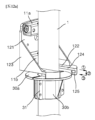
図1は、本発明の一実施例による基地局アンテナ用クランピング装置を示す前方側の下向き斜視図であり、図2は、本発明の一実施例による基地局アンテナ用クランピング装置を示す後方側の下向き斜視図であり、図3は、図1および図2の分解斜視図であり、図4は、本発明の一実施例による基地局アンテナ用クランピング装置のティルティングの様子を示す側面図である。 FIG. 1 is a front downward perspective view showing a clamping device for a base station antenna according to an embodiment of the present invention, and FIG. 2 is a rear perspective view showing a clamping device for a base station antenna according to an embodiment of the present invention. 3 is an exploded perspective view of FIGS. 1 and 2, and FIG. 4 is a side view showing a tilting state of a clamping device for a base station antenna according to an embodiment of the present invention. It is a diagram.
本発明の一実施例による基地局アンテナ用クランピング装置100は、図1~図4に示すように、ガイドアームユニット105と、ティルティング部101とを含む。ガイドアームユニット105は、ティルティング部101のムービングをガイドする役割を果たし、ティルティング部101は、ガイドアームユニット105のガイドを受けながらムービングされることにより、アンテナモジュールAのティルティング角度を調整する役割を果たすことができる。
A base station
ここで、アンテナモジュールAは、少なくとも1つの周波数帯域を有するアンテナ機器(以下、図面符号「A1」と区分して指す)と、アンテナ機器に連結されて、移動通信システムの基地局と移動通信端末との間で弱くなった信号を受けて増幅または再送信し、歪んだ波形を定形化し、タイミングを再調整するなどの機能を行う中継器(RRH、Remote Radio Head)(以下、「RRH」と称し、図面符号「A2」と区分して指す)とを含むことができる。 Here, the antenna module A includes an antenna device having at least one frequency band (hereinafter referred to as "A1" in the drawing) and a base station of a mobile communication system and a mobile communication terminal connected to the antenna device. A repeater (RRH, Remote Radio Head) (hereinafter referred to as ``RRH'') performs functions such as receiving a weakened signal between the terminal and amplifying or retransmitting it, regularizing the distorted waveform, and readjusting the timing. (indicated separately from the drawing reference numeral "A2").
ガイドアームユニット105は、図1および図2に示すように、上下垂直に配置された支柱ポール1に対して直交するように一側に水平に延長配置される。支柱ポール1は、略内部が中空の円筒形状に形成される。このような構成からなる支柱ポール1の外周面に、後述する上部結合クランプ10および載置クランプ30を介して安定的に水平設置される。
As shown in FIGS. 1 and 2, the
本発明の一実施例において、支柱ポール1は、図1および図2に示すように、上下垂直に配置されたものに限定して説明する。しかし、図示しないが、支柱ポール1は、家屋の壁面で水平に配置されてもよいことは当然である。この時、家屋の壁面に水平に配置された支柱ポール1の先端部には、支柱ポール1と直交して結合された不図示の垂直ポールがさらに備えられて、上述した水平地面に対して上下垂直に配置された支柱ポール1の役割を代替することができる。以下では、説明の便宜のために、本発明の一実施例で使う方向に対する用語は、支柱ポール1の実際の設置方向とは関係なく、水平地面に対して上下垂直に配置された支柱ポール1を基準として説明することとする。
In one embodiment of the present invention, the
ガイドアームユニット105は、図1~図4に示すように、ティルティング部101のムービング距離を制限するとともに、ティルティング部101のムービングをガイドする役割を果たす。すなわち、ガイドアームユニット105は、一端は支柱ポール1に結合され、他端は支柱ポール1に対して片持ち梁状に所定長さ延びた位置に備えられることから、ティルティング部101のムービングがガイドアームユニット105の一端と他端との間に制限される。
As shown in FIGS. 1 to 4, the
より詳しくは、ガイドアームユニット105は、図3に示すように、支柱ポール1に対する結合を媒介するハウジングコネクタ120と、ハウジングコネクタ120に連結され、支柱ポール1に対して直交する方向に水平延長されるガイドハウジング110とを含むことができる。
More specifically, as shown in FIG. 3, the
ここで、ガイドハウジング110は、下方が開口した逆「コ」字状の垂直断面を有するように形成される。これは、アンテナモジュールAの上端部との結合を媒介する上部回動リンク41およびティルティング部101のムービング時に干渉されないようにするためである。
Here, the
一方、ハウジングコネクタ120は、後述する支柱ポール1に結合された載置クランプ30に載置された状態で、後述する上部結合クランプ10を介して支柱ポール1に安定的に固定させる役割を果たす。ハウジングコネクタ120の具体的な形状および構造については、後述する載置クランプ30の説明部分でより詳しく説明する。
Meanwhile, the
ティルティング部101は、図1~図4に示すように、ガイドアームユニット105内に配置され、ヒンジの位置が固定されたアンテナモジュールAの下端部を基準として、ガイドアームユニット105内においてアンテナモジュールAの上端部を水平方向にムービングさせて支柱ポール1に対するティルティング角度を調整する役割を果たすことができる。
As shown in FIGS. 1 to 4, the
より詳しくは、アンテナモジュールAは、図3に示すように、その上端部に備えられた上部回動リンク41を介してティルティング部101とヒンジ回動可能に連結され、その下端部に備えられた下部回動リンク42を介して支柱ポール1に対してヒンジ回動可能に連結される。
More specifically, as shown in FIG. 3, the antenna module A is hinge-rotatably connected to the
ここで、支柱ポール1には、図3に示すように、アンテナモジュールAの上端部をティルティングさせるように備えられたガイドアームユニット105の結合を媒介する上部結合クランプ10および載置クランプ30が備えられるとともに、アンテナモジュールAの下端部に連結された下部回動リンク42とのヒンジ結合を媒介するように備えられた回動ブラケット45の結合を媒介する下部結合クランプ20が備えられる。
Here, as shown in FIG. 3, the
上部回動リンク41は、アンテナモジュールAと結合される一端部およびティルティング部101と結合される他端部がすべて相対的にヒンジ回動可能にヒンジ結合され、下部回動リンク42は、アンテナモジュールAと結合される一端部はヒンジ回動不可能に直接ねじ締結され、回動ブラケット45と結合される他端部は相対的にヒンジ回動可能にヒンジ結合される。したがって、上部回動リンク41で連結されたアンテナモジュールAのヒンジの位置は、ティルティング部101のガイドアームユニット105内での位置によって変化するが、下部回動リンク42で連結されたアンテナモジュールAのヒンジの位置は、相対的に固定されたものと定義することができる。
The
図5は、図1および図2の構成のうちティルティング部101を示す側断面図であり、図6は、図1のA-A線に沿った切開斜視図であり、図7は、図1および図2の構成のうちガイドハウジングが除去された状態を示すティルティング部の内部斜視図であり、図8は、図6のB-B線に沿った一部切開斜視図であり、図9は、図5の一部分を拡大した拡大断面図である。
5 is a side sectional view showing the tilting
ティルティング部101は、図5~図9に示すように、ガイドアームユニット105の構成のうちガイドハウジング110内に長手方向に長く設けられ、外周面に雄ねじ山が形成されたスクリューボルト130と、スクリューボルト130に沿って移動し、アンテナモジュールAの上端部と上部回動リンク41によりヒンジ連結されたティルティング駆動部140とを含むことができる。
As shown in FIGS. 5 to 9, the tilting
ここで、スクリューボルト130に形成された雄ねじ山は、詳しく図示しないが、所定サイズのボールが挿入されるボールスクリュー形状およびギヤの噛合が容易な台形形状のいずれか1つを含むことができる。
Although not shown in detail, the male thread formed on the
スクリューボルト130は、支柱ポール1に対して直交するように水平方向に長く配置されたガイドハウジング110の内側一端および内側他端にそれぞれ固定ねじ(図示せず)を用いて固定される。
The
ティルティング駆動部140は、図5~図9に示すように、内部に所定の空間が備えられた駆動部ハウジング141と、駆動部ハウジング141に結合されたモータハウジング142に備えられ、電気的に駆動される駆動モータ143と、モータハウジング142から駆動部ハウジング141側に延びた駆動モータ143の回転軸に連動して回転し、外周面にギヤ歯が備えられた駆動ギヤ145と、回転中心にスクリューボルト130が貫通して結合される雌ねじ山が形成され、外周面に駆動ギヤ145と噛合するギヤ歯が備えられたムービングギヤ144とを含むことができる。
As shown in FIGS. 5 to 9, the tilting
駆動部ハウジング141は、上述した所定の空間が形成されて、駆動ギヤ145とムービングギヤ144が設けられる設置空間としての役割を果たすことはもちろん、いずれか一部はガイドハウジング110の幅方向内側面にそれぞれ固定された後述する一対のガイドレール150に結合され、他の一部はアンテナモジュールAのうちアンテナ機器A1の上端部に上部回動リンク41を介して結合されて、駆動モータ143の駆動によってガイドレール150のガイドを受けながらガイドハウジング110の下側で長手方向(すなわち、水平方向)にアンテナモジュールAの上端部がムービングされることにより、ティルティング角度が調整されるようにする役割を果たす。
The
モータハウジング142は、駆動部ハウジング141の一側に別の空間を形成するように備えられ、モータハウジング142の内部には、駆動モータ143がスクリューボルト130に対して平行に離隔した前記回転軸を有するように固定される。
The
駆動モータ143の回転軸は、モータハウジング142の内部から貫通して駆動部ハウジング141の内側に露出し、駆動モータ143の回転軸を同軸として連動するように駆動ギヤ145が備えられる。
The rotation shaft of the
ここで、ティルティング駆動部140は、図5、図7および図8に示すように、駆動ギヤ145を駆動部ハウジング141に対して回転支持する駆動ベアリング支持部147と、ムービングギヤ144を駆動部ハウジング141に対して回転支持するムービングベアリング支持部146とをさらに含むことができる。
Here, as shown in FIGS. 5, 7, and 8, the tilting
駆動ベアリング支持部147とムービングベアリング支持部146は、それぞれ駆動部ハウジング141内で回転可能に備えられた駆動ギヤ145およびムービングギヤ144を駆動部ハウジング141に対して回転支持する役割を果たし、それぞれ固定状態の内輪と回転状態の外輪との間で摩擦を低減させる複数のベアリングボールが介在したタイプで備えられる。ここで、駆動ベアリング支持部147およびムービングベアリング支持部146の各内輪は、それぞれ駆動部ハウジング141に対して固定され、駆動ベアリング支持部147およびムービングベアリング支持部146の各外輪は、駆動ギヤ145およびムービングギヤ144とともに連動して回転するように備えられる。
The drive
一方、ティルティング駆動部140は、図5~図9に示すように、ガイドアームユニット105の幅方向一側および幅方向他側にそれぞれ配置され、ガイドアームユニット105の長手方向に長く配置された一対のガイドレール150と、駆動部ハウジング141の外側に固定され、一対のガイドレール150それぞれに結合されて駆動部ハウジング141の結合を媒介する一対のムービングガイドブロック160とをさらに含むことができる。
On the other hand, as shown in FIGS. 5 to 9, the tilting
より詳しくは、一対のガイドレール150は、長手方向に長く水平配置されたガイドハウジング110の幅方向一側および幅方向他側にそれぞれ長手方向に長く水平固定される。
More specifically, the pair of
そして、一対のムービングガイドブロック160は、それぞれ一対のガイドレール150の外側面の一部を取り囲みながら係止結合されるように逆「コ」字状の垂直断面形状を有しかつ、駆動部ハウジング141の一側外面および他側外面にそれぞれ固定される。 The pair of moving guide blocks 160 each have an inverted "U"-shaped vertical cross-sectional shape so as to be engaged with each other while surrounding a part of the outer surface of the pair of guide rails 150. 141 is fixed to one side outer surface and the other side outer surface, respectively.
ここで、図6に示すように、一対のガイドレール150と一対のムービングガイドブロック160との間には、ベアリング挿入ホール155が形成され、不図示の複数のベアリングが介在して両者間のティルティングムービングを支持することができる。
Here, as shown in FIG. 6, a bearing
図10は、図1および図2の構成のうち固定クランプ、上部支持クランプおよび下部支持クランプの支柱ポールに対する設置の様子を示す斜視図およびその一部拡大図であり、図11aおよび図11bは、固定クランプの支柱ポールに対する設置過程を示す斜視図であり、図12a~図12cは、ガイド固定ブラケットの支柱ポールに対する設置過程を示す斜視図である。 FIG. 10 is a perspective view and a partially enlarged view showing how the fixed clamp, upper support clamp, and lower support clamp of the configuration of FIGS. 1 and 2 are installed on the support pole, and FIGS. 11a and 11b are 12A to 12C are perspective views showing the installation process of the fixing clamp to the support pole, and FIGS. 12a to 12c are perspective views showing the installation process of the guide fixation bracket to the support pole.
本発明による基地局アンテナ用クランピング装置100の一実施例は、図10~図12cに示すように、支柱ポール1に上下に所定距離離隔して結合された上部結合クランプ10および下部結合クランプ20と、上部結合クランプ10の下側に備えられ、ハウジングコネクタ120を載置固定させる載置クランプ30とをさらに含むことができる。
An embodiment of the
また、上部結合クランプ10は、図10に示すように、支柱ポール1の外周面のうちアンテナモジュールAとの間に相当する外周面に密着する上部一側クランプブロック11a、11bと、支柱ポール1の外周面のうち上部一側クランプブロック11a、11bに対向する反対側の外周面に密着する上部他側クランプブロック12a、12bと、上部一側クランプブロック11a、11bと上部他側クランプブロック12a、12bとを水平に貫通してナット締結される少なくとも2つ以上の上部固定ボルト13とを含むことができる。
In addition, as shown in FIG. 10, the
上部一側クランプブロック11a、11bと、上部他側クランプブロック12a、12bおよび少なくとも2つ以上の上部固定ボルト13は、ガイドアームユニット105を強固に支柱ポール1に媒介結合させる限度ではそれぞれ単一セットで備えられてもよい。本発明の一実施例では、上部一側クランプブロック11a、11bと、上部他側クランプブロック12a、12bおよび少なくとも2つ以上の上部固定ボルト13がそれぞれ2つのセットで備えられて、それぞれガイドアームユニット105の構成のうちハウジングコネクタ120の上側および下側の2箇所を強固に固定させる構造で採用した。
The clamp blocks 11a and 11b on one upper side, the clamp blocks 12a and 12b on the other side, and at least two or more upper fixing
少なくとも2つ以上の上部固定ボルト13は、それぞれ支柱ポール1の外周面一側および他側で、上部一側クランプブロック11a、11bと、上部他側クランプブロック12a、12bおよびガイドアームユニット105の構成のうちハウジングコネクタ120を同時に貫通した後、上部固定ナット14によって締結および固定可能である。
At least two or more upper fixing
一方、下部結合クランプ20は、図10に示すように、支柱ポール1の外周面のうちアンテナモジュールAとの間に相当する外周面に密着する下部一側クランプブロック21と、支柱ポール1の外周面のうち下部一側クランプブロック21に対向する反対側の外周面に密着する下部他側クランプブロック22と、下部一側クランプブロック21と下部他側クランプブロック22とを水平に貫通してナット締結される少なくとも2つ以上の下部固定ボルト23とを含むことができる。
On the other hand, as shown in FIG. 10, the
少なくとも2つ以上の下部固定ボルト23は、それぞれ支柱ポール1の外周面一側および他側で、下部一側クランプブロック21と、下部他側クランプブロック22およびアンテナモジュールAの下端部に連結された下部回動リンク42とのヒンジ結合を媒介するように備えられた回動ブラケット45を同時に貫通した後、下部固定ナット24によって締結および固定可能である。
At least two or more lower fixing
載置クランプ30は、図10~図12cに示すように、支柱ポール1の外周面のうちアンテナモジュールAとの間に相当する外周面に密着結合される内側載置クランプ30aと、支柱ポール1の外周面のうち内側載置クランプ30aに対向する反対側の外周面に密着結合される外側載置クランプ30bとを含み、内側載置クランプ30aと外側載置クランプ30bは、それぞれの面接するフランジ面31’に形成されたボルト貫通孔33を通して貫通する不図示の固定ボルトと、その端部に締結される固定ナットによって支柱ポール1の外周面を全部取り囲むように結合される。
As shown in FIGS. 10 to 12c, the mounting
ここで、載置クランプ30は、図11aおよび図11bに示すように、支柱ポール1の外周面に密着結合される支柱ポール結合部31と、支柱ポール結合部31の上部で放射状に直交して折曲延長され、ハウジングコネクタ120が載置される載置フランジ部32とを含む形状に備えられる。
Here, as shown in FIGS. 11a and 11b, the mounting
図示しないが、支柱ポール結合部31の内側面は、支柱ポール1との関係から摩擦力が増大する材質で備えられたり、摩擦力を形成するセレーション形状に形成されることも可能である。したがって、不図示の固定ボルトおよび固定ナットによる固定力が伝達される場合、支柱ポール結合部31の内側面が支柱ポール1の外周面に強固に密着して自重による下方スリップが防止できる。
Although not shown, the inner surface of the support
載置クランプ30は、ガイドアームユニット105の構成のうちハウジングコネクタ120が安定的に係止固定されるようにする役割を果たすことができる。
The mounting
より詳しくは、ガイドアームユニット105の構成のうちハウジングコネクタ120は、図3(または図12aおよび図12b)を参照すれば、ガイドハウジング110の支柱ポール1側の一端部に面着結合されるように垂直配置された垂直部121と、垂直部121の下端から支柱ポール1の外周面を取り囲みながら載置フランジ部32の上面に面着する水平部122と、水平部122の先端から折曲げられて載置フランジ部32の周縁に係止される係止部125とを含むことができる。これとともに、ハウジングコネクタ120は、垂直部121と水平部122の両端部それぞれを結ぶ形態で一体に備えられた補強部123をさらに含むことができる。
More specifically, in the configuration of the
ここで、ハウジングコネクタ120には、図3(または図12aおよび図12b)に示すように、支柱ポール1に対する組立時、係止部125が支柱ポール1の外周面のうちアンテナモジュールAが位置した側から移動して反対側の支柱ポール1の外周面上に位置した載置クランプ30の載置フランジ部32の先端に流入して係止できるように、略支柱ポール1の外径より大きい内径を有する「U」字状の切開部124が形成される。
Here, as shown in FIG. 3 (or FIGS. 12a and 12b), in the
切開部124は、支柱ポール1の外周面のうち上述した反対側方向に開口するように形成され、係止部125は、それぞれ切開部124の先端部に一対が形成されかつ、載置クランプ30の構成のうち載置フランジ部の厚さよりも大きい係止溝が形成されるように略逆「コ」字状の垂直断面形状を有するように折曲形成される。
The
以下、図11a~図12cを参照して、ガイドアームユニット105を支柱ポール1に固定組立てる過程を簡略に説明する。
Hereinafter, the process of fixing and assembling the
まず、図11aおよび図11bに示すように、載置クランプ30の構成のうち内側載置クランプ30aおよび外側載置クランプ30bを、支柱ポール1の外周面のうちアンテナモジュールAが備えられた側の外周面とその反対側の外周面にそれぞれ密着させた後、貫通ホール33を貫通する不図示の固定ボルトおよび固定ナットを用いて強固に固定させる。
First, as shown in FIGS. 11a and 11b, of the configuration of the mounting
そして、図12aに示すように、ガイドアームユニット105の構成のうちハウジングコネクタ120を、支柱ポール1の外周面のうちアンテナモジュールAまたはガイドハウジング110が備えられた側からその反対側の外周面方向である水平方向に移動させる(図12aの図面符号丸数字の1参照)。この時、ハウジングコネクタ120は、切開部124に形成された「U」字状の内側端が支柱ポール1の外周面の一部を取り囲むように水平移動させることができる。これとともに、ハウジングコネクタ120は、少なくとも載置クランプ30の構成のうち載置フランジ部32の先端に係止部125が嵌合できる位置まで水平方向移動させることが好ましい。
As shown in FIG. 12a, the
次に、図12bおよび図12cに示すように、ハウジングコネクタ120を下方に移動させた後(図12Aの図面符号丸数字の2参照)、ハウジングコネクタ120の係止部125に形成された係止溝(図面符号表記せず)に載置フランジ部の先端が嵌合して係止されるように、ハウジングコネクタ120をアンテナモジュールAまたはガイドハウジング110が備えられた水平方向に移動させる(図12aの図面符号丸数字の3参照)。
Next, as shown in FIGS. 12b and 12c, after the
その後、図12cに示すように、上部結合クランプ10と、少なくとも2つ以上の上部固定ボルト13および上部固定ナット14を用いてハウジングコネクタ120にガイドハウジング110を結合させると、支柱ポール1に対するガイドアームユニット105の組立が完了できる。
Thereafter, as shown in FIG. 12c, when the
図13は、本発明による基地局アンテナ用クランピング装置の多様な設置例を示す側面図である。 FIG. 13 is a side view showing various installation examples of the base station antenna clamping device according to the present invention.
図13(a)は、図1~図12cですでに説明した本発明の一実施例による基地局アンテナ用クランピング装置100のティルティング部101の設置の様子を概略化したものである。
FIG. 13(a) schematically shows how the
すなわち、図13(a)に示される本発明の一実施例による基地局アンテナ用クランピング装置100は、ガイドアームユニット105が支柱ポール1に対して直交するように水平方向に長く延びて配置され、ティルティング部101が水平延長されたガイドアームユニット105に沿ってムービングされることにより、アンテナモジュールAのティルティング角度を調整するように実現されたものである。
That is, in the base station
しかし、本発明の実施例が必ずしも上述した一実施例で実現されるべきではなく、図13(b)に示すように、ガイドアームユニット105が支柱ポール1に対して平行するように垂直方向に長く延びて配置され、ティルティング部101が垂直延長されたガイドアームユニット105に沿ってムービングされることにより、アンテナモジュールAのティルティング角度を調整できるように実現されることも可能である。
However, the embodiment of the present invention should not necessarily be realized by the one embodiment described above, and as shown in FIG. It is also possible to adjust the tilting angle of the antenna module A by moving the tilting
上記のように構成される本発明による基地局用アンテナ装置の実施例は、特にティルティング部101が無線または有線により遠隔で駆動制御できるので、作業者が直接アンテナモジュールAの方向性の調整のために高い位置に設けられた支柱ポール1を通して登る必要がなく、遠隔支援センター(図示せず)のような遠距離でアンテナモジュールAの方向性の調整が可能なため、作業者の便宜性および製品の信頼性を大きく向上させるという利点を提供する。
In the embodiment of the base station antenna device according to the present invention configured as described above, in particular, since the
以上、本発明による基地局用アンテナ装置の実施例を、添付した図面を参照して詳細に説明した。しかし、本発明の実施例が必ずしも上述した実施例によって限定されるものではなく、本発明の属する技術分野における通常の知識を有する者による多様な変形および均等な範囲での実施が可能であることは当然であろう。そのため、本発明の真の権利範囲は後述する特許請求の範囲によって定められる。 The embodiments of the base station antenna device according to the present invention have been described above in detail with reference to the attached drawings. However, the embodiments of the present invention are not necessarily limited to the above-described embodiments, and various modifications and equivalent implementations can be made by those having ordinary knowledge in the technical field to which the present invention pertains. Of course. Therefore, the true scope of rights of the present invention is determined by the claims described below.
本発明は、支柱ポールに装着されたアンテナモジュールを遠隔でティルティング調整することができ、支柱ポールに対する設置および結合が容易な基地局アンテナ用クランピング装置を提供する。 The present invention provides a clamping device for a base station antenna that allows remote tilting adjustment of an antenna module mounted on a support pole and that is easy to install and connect to the support pole.
A:アンテナモジュール A1:アンテナ機器
A2:RRH 1:支柱ポール
10:上部結合クランプ 11a、11b:上部一側クランプブロック
12a、12b:上部他側クランプブロック 13:上部固定ボルト
14:上部固定ナット 20:下部結合クランプ
21:下部一側クランプブロック 22:下部他側クランプブロック
23:2つ以上の固定ボルト 24:2つ以上の固定ナット
30:載置クランプ 30a:内側載置クランプ
30b:外側載置クランプ 41:上部回動リンク
42:下部回動リンク 45:回動ブラケット
100:クランピング装置 101:ティルティング部
105:ガイドアームユニット 110:ガイドハウジング
120:ハウジングコネクタ 121:垂直部
122:水平部 123:補強部
124:切開部 125:係止部
130:スクリューボルト 140:ティルティング駆動部
141:駆動部ハウジング 142:モータハウジング
143:駆動モータ 144:ムービングギヤ
145:駆動ギヤ 146:ムービングベアリング支持部
147:駆動ベアリング支持部 150:ガイドレール
160:ムービングガイドブロック
A: Antenna module A1: Antenna equipment A2: RRH 1: Support pole 10:
Claims (15)
前記ガイドアームユニット内に配置され、ヒンジの位置が固定されたアンテナモジュールの下端部を基準として、前記ガイドアームユニット内において前記アンテナモジュールの上端部を前記水平方向にムービングさせて前記支柱ポールに対するティルティング角度を調整するティルティング部と、を含み、
前記ティルティング部は、
前記ガイドアームユニット内に長手方向に長く設けられ、外周面に雄ねじ山が形成されたスクリューボルトと、
前記スクリューボルトに沿って移動し、前記アンテナモジュールの上端部と上部回動リンクによりヒンジ連結されたティルティング駆動部と、を含む、基地局アンテナ用クランピング装置。 a guide arm unit extending horizontally on one side so as to be orthogonal to the support poles arranged vertically;
The upper end of the antenna module is moved in the horizontal direction within the guide arm unit with reference to the lower end of the antenna module that is disposed within the guide arm unit and has a fixed hinge position, thereby tilting the antenna module relative to the support pole. a tilting part for adjusting the tilting angle ;
The tilting part is
a screw bolt provided longitudinally in the guide arm unit and having a male thread formed on its outer peripheral surface;
A clamping device for a base station antenna, comprising a tilting drive that moves along the screw bolt and is hinged to an upper end of the antenna module by an upper pivot link.
内部に所定の空間が備えられた駆動部ハウジングと、
前記駆動部ハウジングに結合されたモータハウジングに備えられ、電気的に駆動される駆動モータと、
前記モータハウジングから前記駆動部ハウジング側に延びた前記駆動モータの回転軸に連動して回転し、外周面にギヤ歯が備えられた駆動ギヤと、
回転中心に前記スクリューボルトが貫通して結合される雌ねじ山が形成され、外周面に前記駆動ギヤと噛合するギヤ歯が備えられたムービングギヤと、を含む、請求項1に記載の基地局アンテナ用クランピング装置。 The tilting drive unit includes:
a drive unit housing having a predetermined space therein;
an electrically driven drive motor provided in a motor housing coupled to the drive unit housing;
a drive gear that rotates in conjunction with a rotating shaft of the drive motor that extends from the motor housing toward the drive housing, and that has gear teeth on its outer peripheral surface;
The base station antenna according to claim 1, further comprising: a moving gear having a female screw thread formed in the center of rotation to which the screw bolt passes and is coupled, and a moving gear provided with gear teeth meshing with the drive gear on an outer peripheral surface. clamping device.
前記駆動ギヤを前記駆動部ハウジングに対して回転支持する駆動ベアリング支持部と、
前記ムービングギヤを前記駆動部ハウジングに対して回転支持するムービングベアリング支持部と、をさらに含む、請求項2に記載の基地局アンテナ用クランピング装置。 The tilting drive unit includes:
a drive bearing support part that rotatably supports the drive gear with respect to the drive unit housing;
The clamping device for a base station antenna according to claim 2 , further comprising a moving bearing support portion that rotatably supports the moving gear with respect to the drive portion housing.
前記ガイドアームユニットの幅方向一側および幅方向他側にそれぞれ配置され、前記ガイドアームユニットの長手方向に長く配置された一対のガイドレールと、
前記駆動部ハウジングの外側に固定され、前記一対のガイドレールそれぞれに結合されて前記駆動部ハウジングの結合を媒介する一対のムービングガイドブロックと、をさらに含む、請求項2に記載の基地局アンテナ用クランピング装置。 The tilting drive unit includes:
a pair of guide rails arranged on one widthwise side and the other widthwise side of the guide arm unit, respectively, and arranged long in the longitudinal direction of the guide arm unit;
The base station antenna according to claim 2, further comprising a pair of moving guide blocks fixed to the outside of the drive unit housing and coupled to each of the pair of guide rails to mediate coupling of the drive unit housing. Clamping device.
前記ガイドアームユニット内に配置され、ヒンジの位置が固定されたアンテナモジュールの下端部を基準として、前記ガイドアームユニット内において前記アンテナモジュールの上端部を前記水平方向にムービングさせて前記支柱ポールに対するティルティング角度を調整するティルティング部と、を含み、
前記ガイドアームユニットは、
前記支柱ポールに対する結合を媒介するハウジングコネクタと、
前記ハウジングコネクタに連結され、前記支柱ポールに対して直交する方向に水平延長されるガイドハウジングと、を含み、
前記ガイドハウジングは、下方が開口した逆「コ」字状の垂直断面を有する、基地局アンテナ用クランピング装置。 a guide arm unit extending horizontally on one side so as to be orthogonal to the support poles arranged vertically;
The upper end of the antenna module is moved in the horizontal direction within the guide arm unit with reference to the lower end of the antenna module that is disposed within the guide arm unit and has a fixed hinge position, thereby tilting the antenna module relative to the support pole. a tilting part for adjusting the tilting angle;
The guide arm unit is
a housing connector that mediates coupling to the strut pole;
a guide housing connected to the housing connector and extending horizontally in a direction orthogonal to the support pole;
The guide housing is a clamping device for a base station antenna, and the guide housing has an inverted U-shaped vertical cross section with an open bottom.
前記上部結合クランプの下側に備えられ、前記ハウジングコネクタを載置固定させる載置クランプと、をさらに含み、
前記ガイドアームユニットは、
前記ハウジングコネクタが前記載置クランプに載置された後、前記上部結合クランプを介して固定される動作で前記支柱ポールに結合される、請求項5に記載の基地局アンテナ用クランピング装置。 an upper coupling clamp and a lower coupling clamp coupled to the support pole vertically at a predetermined distance apart;
further comprising a mounting clamp provided below the upper coupling clamp for mounting and fixing the housing connector;
The guide arm unit is
The clamping device for a base station antenna according to claim 5 , wherein after the housing connector is placed on the mounting clamp, it is coupled to the support pole in a fixing motion via the upper coupling clamp.
前記下部結合クランプは、前記アンテナモジュールの下端部に固定された下部回動リンクとヒンジ固定される回動ブラケットを介して前記アンテナモジュールと結合される、請求項6に記載の基地局アンテナ用クランピング装置。 the upper coupling clamp is coupled to the guide arm unit hinged to the upper end of the antenna module by an upper pivot link;
The clamp for a base station antenna according to claim 6 , wherein the lower coupling clamp is coupled to the antenna module via a pivot bracket that is hinged to a lower pivot link fixed to a lower end of the antenna module. Ping device.
前記下部回動リンクは、一端部が前記アンテナモジュールに固定され、他端部が前記回動ブラケットにヒンジ回動可能にヒンジ固定される、請求項7に記載の基地局アンテナ用クランピング装置。 The upper rotation link has one end hinge-fixed to the antenna module so as to be hinge-rotatable, and the other end portion hinge-fixed to the guide arm unit so as to be hinge-rotatable;
The clamping device for a base station antenna according to claim 7 , wherein one end of the lower pivot link is fixed to the antenna module, and the other end is hingedly fixed to the pivot bracket so as to be hingedly rotatable.
前記支柱ポールの外周面に密着結合される支柱ポール結合部と、
前記支柱ポール結合部の上部で放射状に直交して折曲延長され、前記ハウジングコネクタが載置される載置フランジ部と、を含む、請求項6に記載の基地局アンテナ用クランピング装置。 The aforementioned mounting clamp is
a strut pole coupling portion tightly coupled to the outer peripheral surface of the strut pole;
7. The clamping device for a base station antenna according to claim 6 , further comprising a mounting flange portion which is bent and extended radially orthogonally above the support pole coupling portion, and on which the housing connector is placed.
前記ガイドハウジングに面着結合されるように垂直配置された垂直部と、
前記垂直部の下端から前記支柱ポールの外周面を取り囲みながら前記載置フランジ部の上面に面着する水平部と、
前記水平部の先端から折曲げられて前記載置フランジ部の周縁に係止される係止部と、を含む、請求項9に記載の基地局アンテナ用クランピング装置。 The housing connector is
a vertical portion vertically arranged to be face-fitted to the guide housing;
a horizontal portion that attaches to the upper surface of the mounting flange portion while surrounding the outer peripheral surface of the support pole from the lower end of the vertical portion;
The clamping device for a base station antenna according to claim 9 , further comprising a locking portion bent from a tip of the horizontal portion and locked to a peripheral edge of the mounting flange portion.
前記支柱ポールの外周面のうち前記アンテナモジュールとの間に相当する外周面に密着する一側クランプブロックと、
前記支柱ポールの外周面のうち前記一側クランプブロックに対向する反対側の外周面に密着する他側クランプブロックと、
前記一側クランプブロックと他側クランプブロックとを貫通してナット締結される少なくとも2つ以上の固定ボルトと、を含む請求項6に記載の基地局アンテナ用クランピング装置。 The upper coupling clamp and the lower coupling clamp are
a one-side clamp block that is in close contact with an outer circumferential surface of the support pole that corresponds to a space between the support pole and the antenna module;
the other side clamp block that is in close contact with the outer circumferential surface of the support pole on the opposite side facing the one side clamp block;
The base station antenna clamping device according to claim 6 , further comprising at least two fixing bolts that pass through the one-side clamp block and the other-side clamp block and are fastened with nuts.
前記ガイドアームユニット内に配置され、ヒンジの位置が固定されたアンテナモジュールの下端部を基準として、前記ガイドアームユニット内において前記アンテナモジュールの上端部を前記水平方向にムービングさせて前記支柱ポールに対するティルティング角度を調整するティルティング部と、を含み、
前記ティルティング部は、無線または有線により遠隔で駆動制御される、基地局アンテナ用クランピング装置。 a guide arm unit extending horizontally on one side so as to be orthogonal to the support poles arranged vertically;
The upper end of the antenna module is moved in the horizontal direction within the guide arm unit with reference to the lower end of the antenna module that is disposed within the guide arm unit and has a fixed hinge position, thereby tilting the antenna module relative to the support pole. a tilting part for adjusting the tilting angle;
The tilting unit is a base station antenna clamping device that is remotely controlled by wireless or wired.
前記ガイドアームユニット内に配置され、ヒンジの位置が固定されたアンテナモジュールの下端部を基準として、前記ガイドアームユニット内において前記アンテナモジュールの上端部を前記垂直方向にムービングさせて前記支柱ポールに対するティルティング角度を調整するティルティング部と、を含む、基地局アンテナ用クランピング装置。 a guide arm unit that extends vertically on one side so as to be parallel to the support poles that are vertically positioned;
The upper end of the antenna module is moved in the vertical direction within the guide arm unit with reference to the lower end of the antenna module which is disposed within the guide arm unit and has a fixed hinge position, thereby tilting the antenna module relative to the support pole. A clamping device for a base station antenna, comprising: a tilting section that adjusts a tilting angle.
Applications Claiming Priority (5)
| Application Number | Priority Date | Filing Date | Title |
|---|---|---|---|
| KR10-2019-0176805 | 2019-12-27 | ||
| KR20190176805 | 2019-12-27 | ||
| KR10-2020-0047510 | 2020-04-20 | ||
| KR1020200047510A KR102355616B1 (en) | 2019-12-27 | 2020-04-20 | Clamping apparatus for base station antenna |
| PCT/KR2020/018779 WO2021133009A1 (en) | 2019-12-27 | 2020-12-21 | Clamping device for base station antenna |
Publications (2)
| Publication Number | Publication Date |
|---|---|
| JP2023508961A JP2023508961A (en) | 2023-03-06 |
| JP7387004B2 true JP7387004B2 (en) | 2023-11-27 |
Family
ID=76575316
Family Applications (1)
| Application Number | Title | Priority Date | Filing Date |
|---|---|---|---|
| JP2022539007A Active JP7387004B2 (en) | 2019-12-27 | 2020-12-21 | Clamping device for base station antenna |
Country Status (6)
| Country | Link |
|---|---|
| US (1) | US20220328949A1 (en) |
| EP (1) | EP4084214A1 (en) |
| JP (1) | JP7387004B2 (en) |
| KR (1) | KR102489855B1 (en) |
| CN (2) | CN115280590A (en) |
| WO (1) | WO2021133009A1 (en) |
Families Citing this family (3)
| Publication number | Priority date | Publication date | Assignee | Title |
|---|---|---|---|---|
| USD993013S1 (en) * | 2021-01-18 | 2023-07-25 | Mafi Ab | Fastening device |
| US11721879B2 (en) * | 2021-10-27 | 2023-08-08 | Dish Wireless L.L.C. | Apparatus for mounting a transceiver to an antenna structure in a cellular communication system |
| WO2023250206A1 (en) * | 2022-06-24 | 2023-12-28 | John Mezzalingua Associates, LLC | Universal mount for dense integration of radio remote units |
Citations (3)
| Publication number | Priority date | Publication date | Assignee | Title |
|---|---|---|---|---|
| JP2005051409A (en) | 2003-07-31 | 2005-02-24 | Hitachi Cable Ltd | Antenna device |
| JP2011078053A (en) | 2009-10-02 | 2011-04-14 | Iwabuchi Corp | Tilt fitting for antenna |
| JP2012034088A (en) | 2010-07-29 | 2012-02-16 | Tcm Corp | Tilt metal fitting for antenna |
Family Cites Families (19)
| Publication number | Priority date | Publication date | Assignee | Title |
|---|---|---|---|---|
| JP3047856B2 (en) * | 1997-05-12 | 2000-06-05 | 日本電気株式会社 | Antenna direction adjustment device |
| KR100323593B1 (en) * | 1998-03-05 | 2002-04-17 | 조정남 | Apparatus for controlling coverage of directional antenna and its method |
| JP2001292015A (en) * | 2000-04-06 | 2001-10-19 | Nippon Antenna Co Ltd | Antenna system |
| KR100478593B1 (en) * | 2002-02-19 | 2005-03-28 | 엘지전자 주식회사 | Antenna System For A Mobile Communication Station |
| KR100943050B1 (en) | 2008-01-15 | 2010-02-19 | 세원텔레텍 주식회사 | Tilting device for wireless communication antenna |
| EP2256857A1 (en) * | 2009-05-15 | 2010-12-01 | Bonczyk, Michael Francis | Rotating mounting assembly |
| KR200456433Y1 (en) * | 2009-08-03 | 2011-10-31 | 주식회사 감마누 | Mounting apparatus of speaker type disguised antenna |
| EP2685557B1 (en) * | 2012-04-20 | 2019-09-11 | Huawei Technologies Co., Ltd. | Antenna and base station |
| GB201208818D0 (en) * | 2012-05-18 | 2012-07-04 | Fasmetrics S A | Antenna azimuth position control |
| SE536614C2 (en) * | 2012-06-11 | 2014-04-01 | Cue Dee Ab | Device for mounting a directional antenna in an adjustable incline position |
| US20160261030A1 (en) * | 2013-11-18 | 2016-09-08 | Kmw Inc. | Antenna device of base station |
| KR102140293B1 (en) * | 2014-02-24 | 2020-08-11 | 주식회사 케이엠더블유 | Multi band antenna device |
| US9972906B2 (en) * | 2015-01-15 | 2018-05-15 | Outthink Technologies, Llc | Two-way antenna mounting bracket and assembly with independently adjustable electromechanical antenna tilt and azimuthal steering for beam reshaping |
| US10630034B2 (en) * | 2015-05-27 | 2020-04-21 | Amphenol Corporation | Integrated antenna unit with blind mate interconnect |
| US10511090B2 (en) * | 2016-07-11 | 2019-12-17 | Sentenia Systems, Inc. | Wireless telecommunication antenna mount and control system |
| US11450940B2 (en) * | 2016-07-11 | 2022-09-20 | Radiarc Technologies, Llc | Mechanical actuators for a wireless telecommunication antenna mount |
| US10944169B2 (en) * | 2016-07-11 | 2021-03-09 | Radiarc Technologies, Llc | Wireless telecommunication antenna mount and control system |
| US11811129B2 (en) * | 2016-07-11 | 2023-11-07 | Radiarc Technologies, Llc | Mechanical actuators for a wireless telecommunication antenna mount |
| CN211238513U (en) * | 2019-12-18 | 2020-08-11 | 康普技术有限责任公司 | Multi-antenna mounting device and multi-antenna assembly |
-
2020
- 2020-12-21 EP EP20905104.4A patent/EP4084214A1/en active Pending
- 2020-12-21 JP JP2022539007A patent/JP7387004B2/en active Active
- 2020-12-21 CN CN202080090052.6A patent/CN115280590A/en active Pending
- 2020-12-21 WO PCT/KR2020/018779 patent/WO2021133009A1/en unknown
- 2020-12-25 CN CN202023180345.XU patent/CN217009530U/en active Active
-
2022
- 2022-01-20 KR KR1020220008694A patent/KR102489855B1/en active IP Right Grant
- 2022-06-23 US US17/847,396 patent/US20220328949A1/en active Pending
Patent Citations (3)
| Publication number | Priority date | Publication date | Assignee | Title |
|---|---|---|---|---|
| JP2005051409A (en) | 2003-07-31 | 2005-02-24 | Hitachi Cable Ltd | Antenna device |
| JP2011078053A (en) | 2009-10-02 | 2011-04-14 | Iwabuchi Corp | Tilt fitting for antenna |
| JP2012034088A (en) | 2010-07-29 | 2012-02-16 | Tcm Corp | Tilt metal fitting for antenna |
Also Published As
| Publication number | Publication date |
|---|---|
| JP2023508961A (en) | 2023-03-06 |
| CN217009530U (en) | 2022-07-19 |
| CN115280590A (en) | 2022-11-01 |
| WO2021133009A1 (en) | 2021-07-01 |
| US20220328949A1 (en) | 2022-10-13 |
| KR20220012986A (en) | 2022-02-04 |
| EP4084214A1 (en) | 2022-11-02 |
| KR102489855B1 (en) | 2023-01-19 |
Similar Documents
| Publication | Publication Date | Title |
|---|---|---|
| JP7387004B2 (en) | Clamping device for base station antenna | |
| US10511090B2 (en) | Wireless telecommunication antenna mount and control system | |
| US20220344798A1 (en) | Base station antenna device and adapter thereof | |
| EP3811462B1 (en) | Moveable antenna apparatus | |
| US20200365985A1 (en) | Wireless telecommunication antenna mount and control system and methods of operating the same | |
| US11450940B2 (en) | Mechanical actuators for a wireless telecommunication antenna mount | |
| KR20140128214A (en) | Antenna unit for base station | |
| KR102157068B1 (en) | Antenna angle adjustment apparatus | |
| KR102355616B1 (en) | Clamping apparatus for base station antenna | |
| US11431091B2 (en) | Wireless telecommunication antenna mount and control system and methods of operating the same | |
| KR20110001415U (en) | Mounting apparatus of speaker type disguised antenna | |
| KR101455691B1 (en) | Antenna fixture for adjusting installed direction | |
| KR20240045168A (en) | Antenna apparatus for base station and adaptor of the same | |
| JP2002299941A (en) | Self-directional antenna and method for self-ranging point of main beam axis | |
| EP4089832A1 (en) | Base station antenna device and adapter thereof | |
| KR102651220B1 (en) | Antenna apparatus for base station and adaptor of the same | |
| US11811129B2 (en) | Mechanical actuators for a wireless telecommunication antenna mount | |
| KR102511595B1 (en) | Mounting apparatus of 5G and LTE antenna | |
| KR20210004806A (en) | Clamping apparatus for antenna | |
| KR102504636B1 (en) | Mounting apparatus for antenna | |
| WO2021226556A1 (en) | Mechanical actuators for a wireless telecommunication antenna mount | |
| KR20210010287A (en) | Clamping apparatus for antenna | |
| KR102566169B1 (en) | Mounting apparatus for antenna | |
| CN216903350U (en) | Slide rail type antenna | |
| US11335989B2 (en) | Sectorized antenna assembly |
Legal Events
| Date | Code | Title | Description |
|---|---|---|---|
| A621 | Written request for application examination |
Free format text: JAPANESE INTERMEDIATE CODE: A621 Effective date: 20220623 |
|
| A131 | Notification of reasons for refusal |
Free format text: JAPANESE INTERMEDIATE CODE: A131 Effective date: 20230711 |
|
| A521 | Request for written amendment filed |
Free format text: JAPANESE INTERMEDIATE CODE: A523 Effective date: 20230922 |
|
| TRDD | Decision of grant or rejection written | ||
| A01 | Written decision to grant a patent or to grant a registration (utility model) |
Free format text: JAPANESE INTERMEDIATE CODE: A01 Effective date: 20231017 |
|
| A61 | First payment of annual fees (during grant procedure) |
Free format text: JAPANESE INTERMEDIATE CODE: A61 Effective date: 20231114 |
|
| R150 | Certificate of patent or registration of utility model |
Ref document number: 7387004 Country of ref document: JP Free format text: JAPANESE INTERMEDIATE CODE: R150 |