EP3113208A1 - Electron microscope - Google Patents
Electron microscope Download PDFInfo
- Publication number
- EP3113208A1 EP3113208A1 EP16176912.0A EP16176912A EP3113208A1 EP 3113208 A1 EP3113208 A1 EP 3113208A1 EP 16176912 A EP16176912 A EP 16176912A EP 3113208 A1 EP3113208 A1 EP 3113208A1
- Authority
- EP
- European Patent Office
- Prior art keywords
- mode
- electron
- vacuum pumping
- pumping unit
- vacuum
- Prior art date
- Legal status (The legal status is an assumption and is not a legal conclusion. Google has not performed a legal analysis and makes no representation as to the accuracy of the status listed.)
- Granted
Links
Images


Classifications
-
- H—ELECTRICITY
- H01—ELECTRIC ELEMENTS
- H01J—ELECTRIC DISCHARGE TUBES OR DISCHARGE LAMPS
- H01J37/00—Discharge tubes with provision for introducing objects or material to be exposed to the discharge, e.g. for the purpose of examination or processing thereof
- H01J37/02—Details
- H01J37/16—Vessels; Containers
-
- H—ELECTRICITY
- H01—ELECTRIC ELEMENTS
- H01J—ELECTRIC DISCHARGE TUBES OR DISCHARGE LAMPS
- H01J37/00—Discharge tubes with provision for introducing objects or material to be exposed to the discharge, e.g. for the purpose of examination or processing thereof
- H01J37/02—Details
- H01J37/18—Vacuum locks ; Means for obtaining or maintaining the desired pressure within the vessel
-
- H—ELECTRICITY
- H01—ELECTRIC ELEMENTS
- H01J—ELECTRIC DISCHARGE TUBES OR DISCHARGE LAMPS
- H01J37/00—Discharge tubes with provision for introducing objects or material to be exposed to the discharge, e.g. for the purpose of examination or processing thereof
- H01J37/02—Details
- H01J37/04—Arrangements of electrodes and associated parts for generating or controlling the discharge, e.g. electron-optical arrangement or ion-optical arrangement
- H01J37/10—Lenses
-
- H—ELECTRICITY
- H01—ELECTRIC ELEMENTS
- H01J—ELECTRIC DISCHARGE TUBES OR DISCHARGE LAMPS
- H01J37/00—Discharge tubes with provision for introducing objects or material to be exposed to the discharge, e.g. for the purpose of examination or processing thereof
- H01J37/02—Details
- H01J37/244—Detectors; Associated components or circuits therefor
-
- H—ELECTRICITY
- H01—ELECTRIC ELEMENTS
- H01J—ELECTRIC DISCHARGE TUBES OR DISCHARGE LAMPS
- H01J37/00—Discharge tubes with provision for introducing objects or material to be exposed to the discharge, e.g. for the purpose of examination or processing thereof
- H01J37/26—Electron or ion microscopes; Electron or ion diffraction tubes
-
- H—ELECTRICITY
- H01—ELECTRIC ELEMENTS
- H01J—ELECTRIC DISCHARGE TUBES OR DISCHARGE LAMPS
- H01J2237/00—Discharge tubes exposing object to beam, e.g. for analysis treatment, etching, imaging
- H01J2237/002—Cooling arrangements
-
- H—ELECTRICITY
- H01—ELECTRIC ELEMENTS
- H01J—ELECTRIC DISCHARGE TUBES OR DISCHARGE LAMPS
- H01J2237/00—Discharge tubes exposing object to beam, e.g. for analysis treatment, etching, imaging
- H01J2237/02—Details
- H01J2237/022—Avoiding or removing foreign or contaminating particles, debris or deposits on sample or tube
-
- H—ELECTRICITY
- H01—ELECTRIC ELEMENTS
- H01J—ELECTRIC DISCHARGE TUBES OR DISCHARGE LAMPS
- H01J2237/00—Discharge tubes exposing object to beam, e.g. for analysis treatment, etching, imaging
- H01J2237/02—Details
- H01J2237/028—Particle traps
-
- H—ELECTRICITY
- H01—ELECTRIC ELEMENTS
- H01J—ELECTRIC DISCHARGE TUBES OR DISCHARGE LAMPS
- H01J2237/00—Discharge tubes exposing object to beam, e.g. for analysis treatment, etching, imaging
- H01J2237/18—Vacuum control means
-
- H—ELECTRICITY
- H01—ELECTRIC ELEMENTS
- H01J—ELECTRIC DISCHARGE TUBES OR DISCHARGE LAMPS
- H01J2237/00—Discharge tubes exposing object to beam, e.g. for analysis treatment, etching, imaging
- H01J2237/18—Vacuum control means
- H01J2237/186—Valves
Definitions
- the present invention relates to an electron microscope.
- TEM transmission electron microscope
- STEM scanning transmission electron microscope
- an electron microscope is equipped with a sample contamination preventive device to maintain the degree of vacuum in the electron optical column and to prevent contamination of the sample.
- a sample contamination preventive device for preventing adsorption of contaminants onto the surface of the sample by surrounding the outer periphery of the sample with cryogenically cooled fins and causing the contaminants (such as hydrocarbon molecules) causing contamination of the sample to be adsorbed onto the fins.
- the fins of the sample contamination preventive device are in thermal contact with a refrigerant tank. This tank is filled with a cryogenic liquid such as liquid nitrogen or liquid helium, whereby the fins are cooled.
- Patent document 1 JP-A-2002-203505
- the cryogenic liquid filled in the refrigerant tank evaporates with the elapse of time. Finally, the liquid will disappear, whereupon the temperature of the fins rises rapidly. Gaseous molecules adsorbed on the fins are released in large quantities. This rapidly impairs the degree of vacuum inside the electron optical column. Consequently, the ion sputter pump evacuating the interior of the electron optical column may be damaged and made inoperable. In some cases, the ion sputter pump is destroyed.
- the user has had to perform manipulations to return the temperature of the fins to room temperature or higher after performing observation and analysis with the electron microscope while using the sample contamination preventive device.
- One object associated with some aspects of the present invention is to provide an electron microscope capable of achieving energy saving easily.
- the controller performs the steps of:
- the controller controls the heating section to heat the adsorptive member. Therefore, energy saving can be easily achieved. Furthermore, in this electron microscope, during the heating of the adsorptive member, the interior of the electron optical column is vacuum pumped by the second vacuum pumping unit; otherwise, gas produced in large quantities would damage the first vacuum pumping unit.
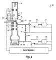
- FIG. 1 schematically shows the electron microscope, 100, associated with the present embodiment.
- the electron microscope 100 is a transmission electron microscope (TEM). That is, the electron microscope 100 is an instrument for focusing electrons transmitted through a sample S and obtaining a transmission electron microscope (TEM) image.
- TEM transmission electron microscope
- the electron microscope 100 includes an electron beam source 10, condenser lenses 12, an objective lens 14, a sample stage 16, a sample holder 17, an intermediate lens 18, a projector lens 20, a detector 22, a cooling section 24, a heating section 26, a first vacuum pumping unit 30, an auxiliary pump 32, a second vacuum pumping unit 40, another auxiliary pump 42, a first vacuum gate valve 50, a second vacuum gate valve 52, and a controller 60.
- the electron beam source 10 produces an electron beam by accelerating electrons, which are emitted from a cathode, by means of an anode.
- a well-known electron gun can be used as the electron beam source 10.
- the condenser lenses 12 are disposed behind (i.e., on the downstream side relative to the direction of travel of an electron beam) the electron beam source 10.
- the condenser lenses 12 are used such that the electron beam emanating from the electron beam source 10 is focused onto the sample S.
- the objective lens 14 is disposed behind the condenser lenses 12.
- the objective lens 14 is an initial stage of lens for imaging the electron beam transmitted through the sample S.
- the objective lens 14 has a top polepiece and a bottom polepiece (both of which are not shown). In the objective lens 14, a magnetic field is produced between the top and bottom polepieces to condense the electron beam.
- the sample stage 16 holds the sample S.
- the sample stage 16 holds the sample S via the sample holder 17.
- the sample stage 16 places the sample S, for example, between the top and bottom polepieces of the objective lens 14.
- the sample stage 16 can move and stop the sample holder 17, and can place the sample S in position.
- the intermediate lens 18 is disposed behind the objective lens 14.
- the projector lens 20 is located behind the intermediate lens 18.
- the intermediate lens 18 and projector lens 20 cooperate to further magnify the image focused by the objective lens 14 and to bring the further magnified image into focus on the detector 22.
- an imaging system is constituted by the objective lens 14, intermediate lens 18, and projector lens 20.
- the detector 22 detects the electrons transmitted through the sample S. Using the detector 22, a TEM image focused by the imaging system can be captured.
- the detector 22 is a digital camera such as a CCD camera or a CMOS camera.
- the cooling section 24 cools cooling fins 242 that are one example of adsorptive member to adsorb contaminant materials (such as gas molecules, e.g, hydrocarbon molecules) contaminating the sample S.
- the cooling section 24 has thermal conductive members 244 and a cooling tank 246, as well as the cooling fins 242.
- the cooling fins 242 are disposed inside the electron optical column 2, and are arranged close to the sample S held to the sample holder 17.
- the cooling fins 242 are in thermal contact with the refrigerant tank 246 via the thermal conductive members 244.
- the cooling fins 242 are cooled by filling the refrigerant tank 246 with a cryogenic liquid such as liquid nitrogen or liquid helium.
- the cooling section 24 acts as a preventive device against contamination of the sample S.
- the adsorptive member for adsorbing contaminant materials that contaminate the sample S has the cooling fins 242.
- No restriction is placed on the shape of the adsorptive member of the cooling section 24 as long as it can adsorb contaminant materials that contaminate the sample S.
- the adsorptive member of the cooling section 24 may be a rod-like member, a plate-like member, or the like.
- the heating section 26 heats the cooling fins 242.
- the heating section 26 is used to heat the cooling fins 242 when the cooling fins 242 are operated to remove gas molecules (such as hydrocarbon molecules) adsorbed on the cooling fins 242. During this degassing process, the cooling fins 242 are heated by the heating section 26 to desorb the gas molecules adsorbed on the cooling fins 242.
- the heating section 26 is configured, for example, including a heater and thermal transfer members for transferring heat generated by the heater to the cooling fins 242.
- the condenser lenses 12, cooling fins 242, objective lens 14, intermediate lens 18, and projector lens 20 are disposed inside the electron optical column 2.
- the sample S is introduced into the electron optical column 2 by the sample holder 17.
- the detector 22 is positioned in a detection chamber (camera chamber) 4.
- the first vacuum pumping unit 30 is connected into the electron optical column 2 via the first vacuum gate valve 50.
- the first vacuum pumping unit 30 is also connected to an exhaust tube 51 that is in communication with the interior of the electron optical column 2.
- the first vacuum gate valve 50 is mounted in the exhaust tube 51.
- the first vacuum pumping unit 30 is a sputter ion pump, for example.
- a sputter ion pump is a vacuum pump that makes use of the gettering action of titanium. Since a sputter ion pump can constitute a vacuum pumping system that uses neither oil nor water, the sputter ion pump is well adapted for pumping of the interior of the electron optical column 2.
- the auxiliary pump 32 is connected to the first vacuum pumping unit 30. An oil rotary pump, a scroll pump, or the like can be used as the auxiliary pump 32.
- the second vacuum pumping unit 40 is connected to the detection chamber 4 and also coupled into the electron optical column 2 via the second vacuum gate valve 52.
- the second vacuum pumping unit 40 is connected to an exhaust tube 53 that is in communication with the detection chamber 4.
- the exhaust tubes 53 and 51 are connected together by an exhaust tube 54. Therefore, the second vacuum pumping unit 40 is connected into the electron optical column 2 by way of the exhaust tubes 53, 54, and 51.
- the second vacuum gate valve 52 is mounted in the exhaust tube 54.
- the interior of the electron optical column 2 can be vacuum pumped with the second vacuum pumping unit 40 by opening the second vacuum gate valve 52.
- the second vacuum pumping unit 40 is a pump capable of operating at pressures higher than pressures at which the first vacuum pumping unit 30 can operate. That is, the second vacuum pumping unit 40 can better cope with rapid increases of gas than the first vacuum pumping unit 30.
- the second vacuum pumping unit 40 is an oil diffusion pump or a turbomolecular pump.
- An oil diffusion pump heats oil to high temperature, blows off the resulting oil vapor from a nozzle at high speed, and conveys the gas molecules while utilizing the momentum of the ejecting stream.
- a turbomolecular pump is a mechanical pump that gives a momentum to gas molecules in the direction of ejection by a rotor rotating at high speed and exhausts the gas molecules.
- the auxiliary pump 42 is connected to the second vacuum pumping unit 40.
- An oil rotary pump, a scroll pump, or the like can be used as the auxiliary pump 42.
- the electron microscope 100 may be equipped with an analytical instrument (not shown) such as an energy-dispersive X-ray spectrometer (EDS) for irradiating the sample S with an electron beam and detecting characteristic X-rays emanating from the sample S or an electron energy loss spectrometer (EELS) for spectrally dispersing the energies of electrons (i.e., inelastically scattered electrons) transmitted through the sample S.
- an analytical instrument such as an energy-dispersive X-ray spectrometer (EDS) for irradiating the sample S with an electron beam and detecting characteristic X-rays emanating from the sample S or an electron energy loss spectrometer (EELS) for spectrally dispersing the energies of electrons (i.e., inelastically scattered electrons) transmitted through the sample S.
- EDS energy-dispersive X-ray spectrometer
- EELS electron energy loss spectrometer
- the controller 60 controls the operation of the component parts constituting the electron microscope 100 such as the electron lenses 12, 14, 18, 20, vacuum pumping units 30, 40, auxiliary pumps 32, 42, and vacuum gate valves 50, 52.
- the controller 60 consists of a CPU (central processing unit) which operates as a computer by executing control programs stored in a storage device (not shown) and which performs various control operations.
- the controller 60 may be made of dedicated circuitry to perform various control operations.
- the controller 60 may have a timer for measuring the time.
- the controller 60 performs an operation to switch the mode of operation of the electron microscope 100 from a first mode in which the microscope 100 is in conditions for microscopic examination to a second mode in which the microscope 100 is in its power saving state.
- the controller 60 also performs an operation to switch the mode of operation from the second mode to the first mode.
- the electron microscope 100 When the electron microscope 100 is in its microscopic examination mode, observation and analysis of the sample S are possible. In this examination mode, contamination of the sample S is prevented by the cooling section 24.
- the refrigerant tank 246 is filled with a cryogenic liquid such as liquid nitrogen or liquid helium, and the cooling fins 242 are cooled.
- the controller 60 activates the electron lenses 12, 14, 18, 20, vacuum pumping units 30, 40, and auxiliary pumps 32, 42. Also, in the first mode, the controller 60 opens the first vacuum gate valve 50 and closes the second vacuum gate valve 52. That is, in the first mode, the first vacuum pumping unit 30 evacuates the interior of the electron optical column 2, and the second vacuum pumping unit 40 pumps down the detection chamber 4.
- the electron microscope 100 When the electron microscope 100 is in its power saving state, in the electron microscope 100, at least the electron lenses 12, 14, 18, and 20 are inoperative. Also, in this power saving state, the second vacuum pumping unit 40 and the auxiliary pump 42 may be rendered inoperative. In addition, in the power saving state, the electron beam source 10 may be inoperative.
- the controller 60 makes the electron lenses 12, 14, 18, 20 inoperative. Also, in the second mode, the controller 60 may deactivate the second vacuum pumping unit 40 and auxiliary pump 42. In this case, the interior of the electron optical column 2 is vacuum pumped by the first vacuum pumping unit 30 but the detection chamber 4 is not evacuated. Furthermore, in the second mode, the controller 60 may also deactivate the electron beam source 10.
- the controller 60 controls the electron microscope 100 on the basis of preset details of a desired operation. For example, during an operation to switch the mode of operation from the first mode to the second mode, the controller 60 can make various settings. For instance, the controller 60 makes a decision as to whether degassing of the cooling fins 242 should be done. The controller 60 determines the date and time at which the mode of operation is switched from the second mode to the first mode. The controller 60 can set the states (e.g., magnification and spot size) of the electron lenses 12, 14, 18, and 20 when a switch is made from the second mode to the first mode.
- the electron microscope 100 has manual control devices such as a touch panel display, a keyboard, a mouse, and so on (not shown) permitting a user to enter these conditions. These conditions are stored in a storage device based on control information from the manual control devices and are set.
- controller 60 controls the mode of operation from the first mode to the second mode and vice versa, respectively.
- FIG. 2 is a flowchart illustrating one example of subroutine for effecting a switch from the first mode to the second mode. When this switch is made, it is assumed that degassing of the cooling fins 242 is scheduled to be done.
- the controller 60 accepts a manual control signal from the manual control device and starts the subroutine for making a switch from the first mode to the second mode.
- controller 60 performs degassing for removing gas molecules adsorbed on the cooling fins 242 (steps S100-S110).
- the controller 60 closes the first vacuum gate valve 50 and opens the second vacuum gate valve 52 (step S 100). Consequently, the interior of the electron optical column 2 that has been vacuum pumped by the first vacuum pumping unit 30 is evacuated by the second vacuum pumping unit 40.
- step S 102 the controller 60 turns off the first vacuum pumping unit 30 (step S 102). As a result, the operation of the first vacuum pumping unit 30 comes to a stop.
- the controller 60 then controls the heating section 26 to initiate heating of the cooling fins 242 (step S 104). For example, the controller 60 operates the heating section 26 for a predetermined time. Consequently, the temperature of the cooling fins 242 can be raised above room temperature. Thus, the gas molecules adsorbed on the cooling fins 242 are released, producing gas inside the electron optical column 2. The gas is expelled by the second vacuum pumping unit 40. The cryogenic liquid filled in the refrigerant tank 246 decreases in volume during the heating of the cooling fins 242 and finally disappears.
- the controller 60 deactivates the heating section 26 (step S106). That is, the controller 60 controls the heating section 26 to heat the cooling fins 242 for the predetermined time.
- the controller 60 may deactivate the heating section 26 on the basis of the results of measurements of the temperature of the cooling fins 242.
- the electron microscope 100 is equipped with a temperature measuring instrument for measuring the temperature of the cooling fins 242.
- the controller 60 makes a decision as to whether the temperature of the cooling fins 242 is above room temperature, based on information about the results of measurements outputted from the temperature measuring instrument. If the temperature of the cooling fins 242 is judged to be above room temperature, the controller 60 deactivates the operation of the heating section 26.
- the controller 60 then turns on the first vacuum pumping unit 30 (step S108). Consequently, the first vacuum pumping unit 30 is made operative.
- the controller 60 then opens the first vacuum gate valve 50 and closes the second vacuum gate valve 52 (step S110). As a consequence, the interior of the electron optical column 2 that has been vacuum pumped by the second vacuum pumping unit 40 is vacuum pumped by the first vacuum pumping unit 30. Because of the processing steps described so far, degassing can be done.
- the controller 60 then turns off the second vacuum pumping unit 40 (step S 112). As a result, the operation of the second vacuum pumping unit 40 is deactivated.
- the controller 60 then turns off the auxiliary pump 42 connected to the second vacuum pumping unit 40 (step S114). As a result, the operation of the auxiliary pump 42 comes to a stop.
- the controller 60 then turns off the electron lenses 12, 14, 18, 20 (step S116). As a result, the operation of the electron lenses 12, 14, 18, 20 comes to a stop.
- the mode of operation can be switched from the first mode to the second mode. Consequently, the electron microscope 100 is placed in its power saving state.
- FIG. 3 is a flowchart illustrating one example of subroutine for effecting a switch from the second mode to the first mode.
- the controller 60 starts the subroutine for making a switch from the second mode to the first mode when a preset date and time arrives.
- the controller 60 first turns on the auxiliary pump 42 connected to the second vacuum pumping unit 40 (step S200). In consequence, the auxiliary pump 42 is made operative.
- the controller 60 then turns on the second vacuum pumping unit 40 (step S202). As a result, the detection chamber 4 is vacuum pumped by the second vacuum pumping unit 40.
- the controller 60 then turns on the electron lenses 12, 14, 18, and 20 (step S204). As a result, the electron lenses 12, 14, 18, and 20 are made operative. Note that no restriction is placed on the order in which these steps S200, S202, and S204 are performed.
- the controller 60 then causes the electron lenses 12, 14, 18, and 20 to be operated under preset lens conditions (step S206). For example, if lens conditions such as final magnification and spot size (i.e., the dose of the electron beam) have been preset by the user, the electron lenses 12, 14, 18, and 20 are controlled to meet the set lens conditions.
- lens conditions such as final magnification and spot size (i.e., the dose of the electron beam) have been preset by the user, the electron lenses 12, 14, 18, and 20 are controlled to meet the set lens conditions.
- the electron microscope 100 has the following features.
- the controller 60 when the controller 60 performs the operation for switching the mode of operation from the first mode where at least the electron lenses 12, 14, 18, 20 are activated to the second mode where at least the electron lenses 12, 14, 18, 20 are deactivated, the controller 60 performs the steps of: closing the first vacuum gate valve 50, opening the second vacuum gate valve 52, and vacuum pumping the interior of the electron optical column 2 by the second vacuum pumping unit 40; then controlling the heating section 26 to heat the cooling fins 242; then opening the first vacuum gate valve 50, closing the second vacuum gate valve 52, and vacuum pumping the interior of the electron optical column 2 by the first vacuum pumping unit 30; and turning off the electron lenses 12, 14, 18, 20.
- the controller 60 controls the heating section 26 to heat the cooling fins 242. This makes it unnecessary for the user to perform a degassing process and thus user's labor can be reduced. Consequently, the electron microscope 100 can be easily placed into its power saving state. Hence, power saving can be easily achieved.
- the cooling fins 242 when the cooling fins 242 are heated, the interior of the electron optical column 2 is pumped down by the second vacuum pumping unit 40; otherwise, the first vacuum pumping unit 30 would be damaged by a large amount of gas produced.
- the controller 60 performs the operation to make a switch from the second mode to the first mode at the preset date and time. If the electron microscope 100 makes a transition from the power saving state to the microscopic examination state, the electron lenses 12, 14, 18, and 20 are turned ON from OFF. The electron lenses 12, 14, 18, and 20 are activated by passing current through their coils. This results in resistive heat, which in turn very slightly deforms the electron lenses 12, 14, 18, and 20. These minute deformations disturb the state of the optical system of the electron microscope and may persist for several hours or more. During this interval, the electron microscope cannot be used under optimum conditions. Therefore, the user has conventionally had to perform a manipulation for making a switch from the second mode to the first mode at a time back calculated from the time at which the electron microscope will be used.
- the controller 60 operates to make a switch from the second mode to the first mode at a preset date and time as described previously. Therefore, user's labor can be reduced. Furthermore, the electron microscope 100 allows for a scheduled operation.
- the controller 60 performs processing to operate the electron lenses 12, 14, 18, and 20 under preset lens conditions.
- the state of each electron lens is controlled by the amount of current flowing through its coil. Therefore, if the state of the electron lens is varied, the electron lens is minutely deformed in the same way as when the electron lens is switched from OFF to ON as described previously. Consequently, in an electron microscope, in order to perform observation and analysis under optimum conditions, it is necessary to previously operate electron lenses under desired optical conditions.
- the electron lenses 12, 14, 16, 18, and 20 are operated under preset lens conditions. Hence, user's labor can be reduced.
- the step of turning off the second vacuum pumping unit 40 is performed. Therefore, when the operation for making a switch from the first mode to the second mode, greater power saving can be achieved, for example, as compared with the case where the step of turning off the second vacuum pumping unit 40 is not performed.
- the electron microscope 100 is a transmission electron microscope where a TEM image is obtained by imaging the electron beam transmitted through the sample S.
- the electron microscope associated with the present invention may also be a scanning transmission electron microscope (STEM) for obtaining an STEM image by scanning the electron beam (electron probe) over the sample S, detecting the intensities either of transmitted waves emanating from various points on the sample or of diffracted waves, and synchronizing the detection of the intensities with the scanning of the electron probe.
- STEM scanning transmission electron microscope
- the present invention embraces configurations substantially identical (e.g., in function and method) with the configurations described in the embodiment of the invention. Furthermore, the invention embraces configurations described in the embodiment and including portions which have non-essential portions replaced. Further, the invention embraces configurations which are similar to the configurations described in the embodiment except that well-known techniques have been added.
Landscapes
- Chemical & Material Sciences (AREA)
- Analytical Chemistry (AREA)
- Analysing Materials By The Use Of Radiation (AREA)
Abstract
Description
- The present invention relates to an electron microscope.
- In an electron microscope such as a transmission electron microscope (TEM) or a scanning transmission electron microscope (STEM), the most power consuming components are electron lenses. In order to achieve power saving in an electron microscope, it is desirable to deactivate the electron lenses when the microscope is not in use.
- Generally, in an electron microscope, the interior of the electron optical column is evacuated by a sputter ion pump, while the interior of the detection chamber (camera chamber) is pumped down by an oil diffusion pump or a turbomolecular pump. Furthermore, an electron microscope is equipped with a sample contamination preventive device to maintain the degree of vacuum in the electron optical column and to prevent contamination of the sample. For example, patent document 1 discloses an electron microscope equipped with a sample contamination preventive device (cooling device) for preventing adsorption of contaminants onto the surface of the sample by surrounding the outer periphery of the sample with cryogenically cooled fins and causing the contaminants (such as hydrocarbon molecules) causing contamination of the sample to be adsorbed onto the fins. The fins of the sample contamination preventive device are in thermal contact with a refrigerant tank. This tank is filled with a cryogenic liquid such as liquid nitrogen or liquid helium, whereby the fins are cooled.
- Patent document 1:
JP-A-2002-203505 - In the sample contamination preventive device, the cryogenic liquid filled in the refrigerant tank evaporates with the elapse of time. Finally, the liquid will disappear, whereupon the temperature of the fins rises rapidly. Gaseous molecules adsorbed on the fins are released in large quantities. This rapidly impairs the degree of vacuum inside the electron optical column. Consequently, the ion sputter pump evacuating the interior of the electron optical column may be damaged and made inoperable. In some cases, the ion sputter pump is destroyed.
- Therefore, the user has had to perform manipulations to return the temperature of the fins to room temperature or higher after performing observation and analysis with the electron microscope while using the sample contamination preventive device.
- In view of the foregoing problem, the present invention has been made. One object associated with some aspects of the present invention is to provide an electron microscope capable of achieving energy saving easily.
- (1) An electron microscope associated with the present invention comprises:
- an electron beam source;
- electron lenses disposed in an electron optical column;
- a cooling section disposed in the electron optical column and operative to cool an adsorptive member to thereby adsorb contaminant materials that contaminate a sample;
- a heating section for heating the adsorptive member;
- a detector disposed in a detection chamber and operative to detect an electron beam transmitted through the sample;
- a first vacuum pumping unit connected into the electron optical column via a first vacuum gate valve;
- a second vacuum pumping unit connected into the detection chamber and also connected into the electron optical column via a second vacuum gate valve, the second vacuum pumping unit being capable of operating at pressures higher than pressures at which the first vacuum pumping unit can operate; and
- a controller for performing an operation to switch the mode of operation of the electron microscope from a first mode where the electron lenses are excited to a second mode where the electron lenses are not excited.
- During the operation to switch the mode of operation from the first mode to the second mode, the controller performs the steps of:
- closing the first vacuum gate valve, opening the second vacuum gate valve, and vacuum pumping the interior of the electron optical column by the second vacuum pumping unit;
- then controlling the heating section to heat the adsorptive member;
- then opening the first vacuum gate valve, closing the second vacuum gate valve, and vacuum pumping the interior of the electron optical column by the first vacuum pumping unit; and
- turning off the electron lenses.
- In this electron microscope, during the operation to switch the mode of operation from the first mode to the second mode, the controller controls the heating section to heat the adsorptive member. Therefore, energy saving can be easily achieved. Furthermore, in this electron microscope, during the heating of the adsorptive member, the interior of the electron optical column is vacuum pumped by the second vacuum pumping unit; otherwise, gas produced in large quantities would damage the first vacuum pumping unit.
- (2) In one feature of this electron microscope, the controller may perform the step of switching the mode of operation from the second mode to the first mode at a preset date and time.
In this electron microscope, the controller performs the step of switching the mode of operation from the second mode to the first mode at the preset date and time and, therefore, user's labor can be reduced. - (3) In one feature of this electron microscope of (2), during the operation for switching the mode of operation from the second mode to the first mode, the controller may perform the step of operating the electron lenses under preset lens conditions.
In this electron microscope, during the operation to switch the mode of operation from the second mode to the first mode, the controller performs the step of operating the electron lenses under the preset lens conditions. Consequently, user's labor can be reduced. - (4) In an electron microscope of any one of (1)-(3), during the operation for switching the mode of operation from the first mode to the second mode, the controller may perform the step of turning off the second vacuum pumping unit after the step of vacuum pumping the interior of the electron optical column by the first vacuum pumping unit.
In this electron microscope, a greater energy saving can be accomplished, for example, as compared with the case where the step of turning off the second vacuum pumping unit is not performed. - (5) In one feature of the electron microscope of any one of (1)-(4), the first vacuum pumping unit may be a sputter ion pump, while the second vacuum pumping unit may be an oil diffusion pump or a turbomolecular pump.
-
-
FIG. 1 is a schematic view, partly in block form, of an electron microscope associated with one embodiment of the present invention. -
FIG. 2 is a flowchart illustrating one example of subroutine for switching the mode of operation of the electron microscope ofFIG. 1 from a first mode to a second mode. -
FIG. 3 is a flowchart illustrating one example of subroutine for switching the mode of operation from the second mode back to the first mode. - The preferred embodiment of the present invention is hereinafter described in detail with reference to the drawings. It is to be understood that the embodiment described below is not intended to unduly restrict the content of the present invention delineated by the claims and that not all the configurations described below are essential constituent components of the invention.
- An electron microscope associated with an embodiment of the present invention is first described by referring to
FIG. 1 , which schematically shows the electron microscope, 100, associated with the present embodiment. - The
electron microscope 100 is a transmission electron microscope (TEM). That is, theelectron microscope 100 is an instrument for focusing electrons transmitted through a sample S and obtaining a transmission electron microscope (TEM) image. - Referring still to
FIG. 1 , theelectron microscope 100 includes anelectron beam source 10,condenser lenses 12, anobjective lens 14, asample stage 16, asample holder 17, anintermediate lens 18, aprojector lens 20, adetector 22, acooling section 24, aheating section 26, a firstvacuum pumping unit 30, anauxiliary pump 32, a secondvacuum pumping unit 40, anotherauxiliary pump 42, a firstvacuum gate valve 50, a secondvacuum gate valve 52, and acontroller 60. - The
electron beam source 10 produces an electron beam by accelerating electrons, which are emitted from a cathode, by means of an anode. For instance, a well-known electron gun can be used as theelectron beam source 10. - The
condenser lenses 12 are disposed behind (i.e., on the downstream side relative to the direction of travel of an electron beam) theelectron beam source 10. Thecondenser lenses 12 are used such that the electron beam emanating from theelectron beam source 10 is focused onto the sample S. - The
objective lens 14 is disposed behind thecondenser lenses 12. Theobjective lens 14 is an initial stage of lens for imaging the electron beam transmitted through the sample S. Theobjective lens 14 has a top polepiece and a bottom polepiece (both of which are not shown). In theobjective lens 14, a magnetic field is produced between the top and bottom polepieces to condense the electron beam. - The
sample stage 16 holds the sample S. In the illustrated example, thesample stage 16 holds the sample S via thesample holder 17. Thesample stage 16 places the sample S, for example, between the top and bottom polepieces of theobjective lens 14. Thesample stage 16 can move and stop thesample holder 17, and can place the sample S in position. - The
intermediate lens 18 is disposed behind theobjective lens 14. Theprojector lens 20 is located behind theintermediate lens 18. Theintermediate lens 18 andprojector lens 20 cooperate to further magnify the image focused by theobjective lens 14 and to bring the further magnified image into focus on thedetector 22. In theelectron microscope 100, an imaging system is constituted by theobjective lens 14,intermediate lens 18, andprojector lens 20. - The
detector 22 detects the electrons transmitted through the sample S. Using thedetector 22, a TEM image focused by the imaging system can be captured. For example, thedetector 22 is a digital camera such as a CCD camera or a CMOS camera. - The
cooling section 24 cools coolingfins 242 that are one example of adsorptive member to adsorb contaminant materials (such as gas molecules, e.g, hydrocarbon molecules) contaminating the sample S. Thecooling section 24 has thermalconductive members 244 and acooling tank 246, as well as the coolingfins 242. The coolingfins 242 are disposed inside the electronoptical column 2, and are arranged close to the sample S held to thesample holder 17. The coolingfins 242 are in thermal contact with therefrigerant tank 246 via the thermalconductive members 244. The coolingfins 242 are cooled by filling therefrigerant tank 246 with a cryogenic liquid such as liquid nitrogen or liquid helium. As a result, contaminant materials that contaminate the sample S such as hydrocarbon molecules can be adsorbed onto the coolingfins 242. Hence, the sample S can be prevented from being contaminated. Thus, thecooling section 24 acts as a preventive device against contamination of the sample S. - In this example, the adsorptive member for adsorbing contaminant materials that contaminate the sample S has the cooling
fins 242. No restriction is placed on the shape of the adsorptive member of thecooling section 24 as long as it can adsorb contaminant materials that contaminate the sample S. The adsorptive member of thecooling section 24 may be a rod-like member, a plate-like member, or the like. - The
heating section 26 heats the coolingfins 242. Theheating section 26 is used to heat the coolingfins 242 when the coolingfins 242 are operated to remove gas molecules (such as hydrocarbon molecules) adsorbed on the coolingfins 242. During this degassing process, the coolingfins 242 are heated by theheating section 26 to desorb the gas molecules adsorbed on the coolingfins 242. Theheating section 26 is configured, for example, including a heater and thermal transfer members for transferring heat generated by the heater to the coolingfins 242. - In the
electron microscope 100, thecondenser lenses 12, coolingfins 242,objective lens 14,intermediate lens 18, andprojector lens 20 are disposed inside the electronoptical column 2. The sample S is introduced into the electronoptical column 2 by thesample holder 17. Furthermore, in theelectron microscope 100, thedetector 22 is positioned in a detection chamber (camera chamber) 4. - The first
vacuum pumping unit 30 is connected into the electronoptical column 2 via the firstvacuum gate valve 50. The firstvacuum pumping unit 30 is also connected to anexhaust tube 51 that is in communication with the interior of the electronoptical column 2. The firstvacuum gate valve 50 is mounted in theexhaust tube 51. - The first
vacuum pumping unit 30 is a sputter ion pump, for example. A sputter ion pump is a vacuum pump that makes use of the gettering action of titanium. Since a sputter ion pump can constitute a vacuum pumping system that uses neither oil nor water, the sputter ion pump is well adapted for pumping of the interior of the electronoptical column 2. Theauxiliary pump 32 is connected to the firstvacuum pumping unit 30. An oil rotary pump, a scroll pump, or the like can be used as theauxiliary pump 32. - The second
vacuum pumping unit 40 is connected to thedetection chamber 4 and also coupled into the electronoptical column 2 via the secondvacuum gate valve 52. The secondvacuum pumping unit 40 is connected to anexhaust tube 53 that is in communication with thedetection chamber 4. Theexhaust tubes exhaust tube 54. Therefore, the secondvacuum pumping unit 40 is connected into the electronoptical column 2 by way of theexhaust tubes vacuum gate valve 52 is mounted in theexhaust tube 54. The interior of the electronoptical column 2 can be vacuum pumped with the secondvacuum pumping unit 40 by opening the secondvacuum gate valve 52. - The second
vacuum pumping unit 40 is a pump capable of operating at pressures higher than pressures at which the firstvacuum pumping unit 30 can operate. That is, the secondvacuum pumping unit 40 can better cope with rapid increases of gas than the firstvacuum pumping unit 30. For example, the secondvacuum pumping unit 40 is an oil diffusion pump or a turbomolecular pump. An oil diffusion pump heats oil to high temperature, blows off the resulting oil vapor from a nozzle at high speed, and conveys the gas molecules while utilizing the momentum of the ejecting stream. A turbomolecular pump is a mechanical pump that gives a momentum to gas molecules in the direction of ejection by a rotor rotating at high speed and exhausts the gas molecules. Theauxiliary pump 42 is connected to the secondvacuum pumping unit 40. An oil rotary pump, a scroll pump, or the like can be used as theauxiliary pump 42. - The
electron microscope 100 may be equipped with an analytical instrument (not shown) such as an energy-dispersive X-ray spectrometer (EDS) for irradiating the sample S with an electron beam and detecting characteristic X-rays emanating from the sample S or an electron energy loss spectrometer (EELS) for spectrally dispersing the energies of electrons (i.e., inelastically scattered electrons) transmitted through the sample S. - The
controller 60 controls the operation of the component parts constituting theelectron microscope 100 such as theelectron lenses vacuum pumping units vacuum gate valves controller 60 consists of a CPU (central processing unit) which operates as a computer by executing control programs stored in a storage device (not shown) and which performs various control operations. Alternatively, thecontroller 60 may be made of dedicated circuitry to perform various control operations. Thecontroller 60 may have a timer for measuring the time. - The
controller 60 performs an operation to switch the mode of operation of theelectron microscope 100 from a first mode in which themicroscope 100 is in conditions for microscopic examination to a second mode in which themicroscope 100 is in its power saving state. Thecontroller 60 also performs an operation to switch the mode of operation from the second mode to the first mode. - When the
electron microscope 100 is in its microscopic examination mode, observation and analysis of the sample S are possible. In this examination mode, contamination of the sample S is prevented by thecooling section 24. In particular, therefrigerant tank 246 is filled with a cryogenic liquid such as liquid nitrogen or liquid helium, and the coolingfins 242 are cooled. - When the
electron microscope 100 is in the first mode where the microscope is in conditions for microscopic examination, thecontroller 60 activates theelectron lenses vacuum pumping units auxiliary pumps controller 60 opens the firstvacuum gate valve 50 and closes the secondvacuum gate valve 52. That is, in the first mode, the firstvacuum pumping unit 30 evacuates the interior of the electronoptical column 2, and the secondvacuum pumping unit 40 pumps down thedetection chamber 4. - When the
electron microscope 100 is in its power saving state, in theelectron microscope 100, at least theelectron lenses vacuum pumping unit 40 and theauxiliary pump 42 may be rendered inoperative. In addition, in the power saving state, theelectron beam source 10 may be inoperative. - In the second mode where the
electron microscope 100 is in its power saving state, thecontroller 60 makes theelectron lenses controller 60 may deactivate the secondvacuum pumping unit 40 andauxiliary pump 42. In this case, the interior of the electronoptical column 2 is vacuum pumped by the firstvacuum pumping unit 30 but thedetection chamber 4 is not evacuated. Furthermore, in the second mode, thecontroller 60 may also deactivate theelectron beam source 10. - The
controller 60 controls theelectron microscope 100 on the basis of preset details of a desired operation. For example, during an operation to switch the mode of operation from the first mode to the second mode, thecontroller 60 can make various settings. For instance, thecontroller 60 makes a decision as to whether degassing of the coolingfins 242 should be done. Thecontroller 60 determines the date and time at which the mode of operation is switched from the second mode to the first mode. Thecontroller 60 can set the states (e.g., magnification and spot size) of theelectron lenses electron microscope 100 has manual control devices such as a touch panel display, a keyboard, a mouse, and so on (not shown) permitting a user to enter these conditions. These conditions are stored in a storage device based on control information from the manual control devices and are set. - The operations of the
controller 60 to switch the mode of operation from the first mode to the second mode and vice versa, respectively, are described below. - The operation for causing a switch from the first mode to the second mode is first described.
FIG. 2 is a flowchart illustrating one example of subroutine for effecting a switch from the first mode to the second mode. When this switch is made, it is assumed that degassing of the coolingfins 242 is scheduled to be done. - When the
electron microscope 100 is in its microscopic examination state, if the user asks for a switch to the power saving state via a manual control device, thecontroller 60 accepts a manual control signal from the manual control device and starts the subroutine for making a switch from the first mode to the second mode. - First, the
controller 60 performs degassing for removing gas molecules adsorbed on the cooling fins 242 (steps S100-S110). - In particular, the
controller 60 closes the firstvacuum gate valve 50 and opens the second vacuum gate valve 52 (step S 100). Consequently, the interior of the electronoptical column 2 that has been vacuum pumped by the firstvacuum pumping unit 30 is evacuated by the secondvacuum pumping unit 40. - Then, the
controller 60 turns off the first vacuum pumping unit 30 (step S 102). As a result, the operation of the firstvacuum pumping unit 30 comes to a stop. - The
controller 60 then controls theheating section 26 to initiate heating of the cooling fins 242 (step S 104). For example, thecontroller 60 operates theheating section 26 for a predetermined time. Consequently, the temperature of the coolingfins 242 can be raised above room temperature. Thus, the gas molecules adsorbed on the coolingfins 242 are released, producing gas inside the electronoptical column 2. The gas is expelled by the secondvacuum pumping unit 40. The cryogenic liquid filled in therefrigerant tank 246 decreases in volume during the heating of the coolingfins 242 and finally disappears. - When the predetermined time passes, the
controller 60 deactivates the heating section 26 (step S106). That is, thecontroller 60 controls theheating section 26 to heat the coolingfins 242 for the predetermined time. - Alternatively, the
controller 60 may deactivate theheating section 26 on the basis of the results of measurements of the temperature of the coolingfins 242. For example, theelectron microscope 100 is equipped with a temperature measuring instrument for measuring the temperature of the coolingfins 242. Thecontroller 60 makes a decision as to whether the temperature of the coolingfins 242 is above room temperature, based on information about the results of measurements outputted from the temperature measuring instrument. If the temperature of the coolingfins 242 is judged to be above room temperature, thecontroller 60 deactivates the operation of theheating section 26. - The
controller 60 then turns on the first vacuum pumping unit 30 (step S108). Consequently, the firstvacuum pumping unit 30 is made operative. - The
controller 60 then opens the firstvacuum gate valve 50 and closes the second vacuum gate valve 52 (step S110). As a consequence, the interior of the electronoptical column 2 that has been vacuum pumped by the secondvacuum pumping unit 40 is vacuum pumped by the firstvacuum pumping unit 30. Because of the processing steps described so far, degassing can be done. - The
controller 60 then turns off the second vacuum pumping unit 40 (step S 112). As a result, the operation of the secondvacuum pumping unit 40 is deactivated. - The
controller 60 then turns off theauxiliary pump 42 connected to the second vacuum pumping unit 40 (step S114). As a result, the operation of theauxiliary pump 42 comes to a stop. - The
controller 60 then turns off theelectron lenses electron lenses - Because of the processing steps described thus far, the mode of operation can be switched from the first mode to the second mode. Consequently, the
electron microscope 100 is placed in its power saving state. - The operation for making a switch from the second mode to the first mode is next described.
FIG. 3 is a flowchart illustrating one example of subroutine for effecting a switch from the second mode to the first mode. - When the
electron microscope 100 is in its power saving state, thecontroller 60 starts the subroutine for making a switch from the second mode to the first mode when a preset date and time arrives. - The
controller 60 first turns on theauxiliary pump 42 connected to the second vacuum pumping unit 40 (step S200). In consequence, theauxiliary pump 42 is made operative. - The
controller 60 then turns on the second vacuum pumping unit 40 (step S202). As a result, thedetection chamber 4 is vacuum pumped by the secondvacuum pumping unit 40. - The
controller 60 then turns on theelectron lenses electron lenses - The
controller 60 then causes theelectron lenses electron lenses - Because of the processing steps described so far, it is possible to cause a switch from the second mode to the first mode. Consequently, the
electron microscope 100 is put in its microscopic examination state. - The
electron microscope 100 has the following features. In theelectron microscope 100, when thecontroller 60 performs the operation for switching the mode of operation from the first mode where at least theelectron lenses electron lenses controller 60 performs the steps of: closing the firstvacuum gate valve 50, opening the secondvacuum gate valve 52, and vacuum pumping the interior of the electronoptical column 2 by the secondvacuum pumping unit 40; then controlling theheating section 26 to heat the coolingfins 242; then opening the firstvacuum gate valve 50, closing the secondvacuum gate valve 52, and vacuum pumping the interior of the electronoptical column 2 by the firstvacuum pumping unit 30; and turning off theelectron lenses electron microscope 100, during the operation for making a switch from the first mode to the second mode, thecontroller 60 controls theheating section 26 to heat the coolingfins 242. This makes it unnecessary for the user to perform a degassing process and thus user's labor can be reduced. Consequently, theelectron microscope 100 can be easily placed into its power saving state. Hence, power saving can be easily achieved. - Furthermore, in the
electron microscope 100, when the coolingfins 242 are heated, the interior of the electronoptical column 2 is pumped down by the secondvacuum pumping unit 40; otherwise, the firstvacuum pumping unit 30 would be damaged by a large amount of gas produced. - In the
electron microscope 100, thecontroller 60 performs the operation to make a switch from the second mode to the first mode at the preset date and time. If theelectron microscope 100 makes a transition from the power saving state to the microscopic examination state, theelectron lenses electron lenses electron lenses - In contrast, in the
electron microscope 100, thecontroller 60 operates to make a switch from the second mode to the first mode at a preset date and time as described previously. Therefore, user's labor can be reduced. Furthermore, theelectron microscope 100 allows for a scheduled operation. - In the
electron microscope 100, during the operation of making a switch from the second mode to the first mode, thecontroller 60 performs processing to operate theelectron lenses electron microscope 100, as described previously, during the operation of thecontroller 60 for making a switch from the second mode to the first mode, theelectron lenses - In the
electron microscope 100, during the operation for making a switch from the first mode to the second mode, after the step of vacuum pumping the interior of the electronoptical column 2 by the firstvacuum pumping unit 30, the step of turning off the secondvacuum pumping unit 40 is performed. Therefore, when the operation for making a switch from the first mode to the second mode, greater power saving can be achieved, for example, as compared with the case where the step of turning off the secondvacuum pumping unit 40 is not performed. - It is to be understood that the present invention is not restricted to the foregoing embodiment but rather can be practiced in various modified forms without departing from the scope and gist of the invention.
- In the above embodiment, an example has been described in which the
electron microscope 100 is a transmission electron microscope where a TEM image is obtained by imaging the electron beam transmitted through the sample S. The electron microscope associated with the present invention may also be a scanning transmission electron microscope (STEM) for obtaining an STEM image by scanning the electron beam (electron probe) over the sample S, detecting the intensities either of transmitted waves emanating from various points on the sample or of diffracted waves, and synchronizing the detection of the intensities with the scanning of the electron probe. - The present invention embraces configurations substantially identical (e.g., in function and method) with the configurations described in the embodiment of the invention. Furthermore, the invention embraces configurations described in the embodiment and including portions which have non-essential portions replaced. Further, the invention embraces configurations which are similar to the configurations described in the embodiment except that well-known techniques have been added.
Claims (5)
- An electron microscope comprising:an electron beam source;electron lenses disposed in an electron optical column;a cooling section disposed in the electron optical column and operative to cool an adsorptive member to thereby adsorb contaminant materials that contaminate a sample;a heating section for heating the adsorptive member;a detector disposed in a detection chamber and operative to detect an electron beam transmitted through the sample;a first vacuum pumping unit connected into the electron optical column via a first vacuum gate valve;a second vacuum pumping unit connected into the detection chamber and also connected into the electron optical column via a second vacuum gate valve, the second vacuum pumping unit being capable of operating at pressures higher than pressures at which the first vacuum pumping unit can operate; anda controller for performing an operation to switch the mode of operation of the electron microscope from a first mode where the electron lenses are excited to a second mode where the electron lenses are not excited;wherein, during said operation to switch the mode of operation from the first mode to the second mode, the controller performs the steps of:closing the first vacuum gate valve, opening the second vacuum gate valve, and vacuum pumping the interior of the electron optical column by the second vacuum pumping unit;then controlling the heating section to heat the adsorptive member;then opening the first vacuum gate valve, closing the second vacuum gate valve, and vacuum pumping the interior of the electron optical column by the first vacuum pumping unit; andturning off the electron lenses.
- An electron microscope as set forth in claim 1, wherein said controller further performs the step of switching the mode of operation from the second mode to the first mode at a preset date and time.
- An electron microscope as set forth in claim 2, wherein, during said operation for switching the mode of operation from the second mode to the first mode, said controller performs the step of operating said electron lenses under preset lens conditions.
- An electron microscope as set forth in any one of claim 1 to 3, wherein, during said operation for switching the mode of operation from the first mode to the second mode, said controller performs the step of turning off said second vacuum pumping unit after the step of vacuum pumping the interior of said electron optical column by said first vacuum pumping unit.
- An electron microscope as set forth in any one of claims 1 to 4, wherein said first vacuum pumping unit is a sputter ion pump, while said second vacuum pumping unit is an oil diffusion pump or a turbomolecular pump.
Applications Claiming Priority (1)
| Application Number | Priority Date | Filing Date | Title |
|---|---|---|---|
| JP2015130715A JP6464048B2 (en) | 2015-06-30 | 2015-06-30 | electronic microscope |
Publications (2)
| Publication Number | Publication Date |
|---|---|
| EP3113208A1 true EP3113208A1 (en) | 2017-01-04 |
| EP3113208B1 EP3113208B1 (en) | 2024-01-03 |
Family
ID=56561203
Family Applications (1)
| Application Number | Title | Priority Date | Filing Date |
|---|---|---|---|
| EP16176912.0A Active EP3113208B1 (en) | 2015-06-30 | 2016-06-29 | Electron microscope |
Country Status (3)
| Country | Link |
|---|---|
| US (1) | US9773639B2 (en) |
| EP (1) | EP3113208B1 (en) |
| JP (1) | JP6464048B2 (en) |
Families Citing this family (3)
| Publication number | Priority date | Publication date | Assignee | Title |
|---|---|---|---|---|
| CN110137065B (en) * | 2019-05-17 | 2024-07-23 | 中国科学院理化技术研究所 | Temperature regulating system and method for scanning electron microscope |
| CN112345419A (en) * | 2020-10-23 | 2021-02-09 | 大连理工大学 | A nanobubble in-situ observation device and method |
| US20240170320A1 (en) * | 2022-11-23 | 2024-05-23 | Taiwan Semiconductor Manufacturing Company, Ltd. | Die bonding device, die bonding method and vacuum control method for pick-and-placer thereof |
Citations (2)
| Publication number | Priority date | Publication date | Assignee | Title |
|---|---|---|---|---|
| JP2002203505A (en) | 2000-12-28 | 2002-07-19 | Jeol Ltd | Pre-evacuation method and pre-evacuation chamber in analytical electron microscope |
| US20130256558A1 (en) * | 2012-03-29 | 2013-10-03 | Christian Dietl | Apparatus for contaminants being deposited thereon |
Family Cites Families (7)
| Publication number | Priority date | Publication date | Assignee | Title |
|---|---|---|---|---|
| JPS6134841A (en) * | 1984-07-27 | 1986-02-19 | Hitachi Ltd | High vacuum electron microscope |
| JPS6387760U (en) * | 1986-11-28 | 1988-06-08 | ||
| JPH04190550A (en) * | 1990-11-26 | 1992-07-08 | Hitachi Ltd | Transmission electron microscope |
| JPH0511061A (en) * | 1991-07-05 | 1993-01-19 | Jeol Ltd | Energy dispersive X-ray detector |
| JP5236037B2 (en) * | 2011-03-25 | 2013-07-17 | 株式会社日立ハイテクノロジーズ | Mirror electronic sample inspection equipment |
| JP6035598B2 (en) * | 2012-07-27 | 2016-11-30 | 株式会社日立ハイテクノロジーズ | Charged particle beam equipment |
| JP6302702B2 (en) * | 2014-02-27 | 2018-03-28 | 株式会社日立ハイテクノロジーズ | Scanning electron microscope and image generation method |
-
2015
- 2015-06-30 JP JP2015130715A patent/JP6464048B2/en active Active
-
2016
- 2016-06-29 US US15/196,149 patent/US9773639B2/en active Active
- 2016-06-29 EP EP16176912.0A patent/EP3113208B1/en active Active
Patent Citations (2)
| Publication number | Priority date | Publication date | Assignee | Title |
|---|---|---|---|---|
| JP2002203505A (en) | 2000-12-28 | 2002-07-19 | Jeol Ltd | Pre-evacuation method and pre-evacuation chamber in analytical electron microscope |
| US20130256558A1 (en) * | 2012-03-29 | 2013-10-03 | Christian Dietl | Apparatus for contaminants being deposited thereon |
Non-Patent Citations (1)
| Title |
|---|
| "JEOL 2100 Basic operating instructions", May 2012 (2012-05-01), XP055319714, Retrieved from the Internet <URL:http://www.ammrf.org.au/myscope/docs/tem/JEOL2100_Basic_Manual_2011-12-08_editedBC.pdf> [retrieved on 20161115] * |
Also Published As
| Publication number | Publication date |
|---|---|
| US9773639B2 (en) | 2017-09-26 |
| JP6464048B2 (en) | 2019-02-06 |
| EP3113208B1 (en) | 2024-01-03 |
| US20170025244A1 (en) | 2017-01-26 |
| JP2017016818A (en) | 2017-01-19 |
Similar Documents
| Publication | Publication Date | Title |
|---|---|---|
| US7132673B2 (en) | Device and method for milling of material using ions | |
| US8263943B2 (en) | Ion beam device | |
| JP6093752B2 (en) | Ion beam equipment | |
| US10170275B2 (en) | Cryogenic specimen processing in a charged particle microscope | |
| US20130126731A1 (en) | Charged Particle Microscope and Ion Microscope | |
| JP6043476B2 (en) | Ion source and ion beam apparatus using the same | |
| JP2009163981A (en) | Gas field ionization ion source, charged particle microscope, and apparatus | |
| US10636623B2 (en) | Ion beam device | |
| EP3113208B1 (en) | Electron microscope | |
| JP2018186076A (en) | Aberration measurement in charged particle microscope | |
| JP6172690B2 (en) | Anti-contamination trap and vacuum application equipment | |
| KR102279130B1 (en) | Ion beam apparatus | |
| JP2017016810A (en) | Charged particle beam device and temperature control method of sample holder | |
| JP6696019B2 (en) | Ion beam device and method of operating the same | |
| EP3477682B1 (en) | Improved sims secondary ion mass spectrometry technique | |
| JP2011138649A (en) | Electron microscope | |
| JP5969586B2 (en) | Ion beam equipment | |
| JP2002313270A (en) | High vacuum electron beam apparatus and exhaust method therefor | |
| JP2014149919A (en) | Ion beam device and method of removing impurity gas | |
| EP3477683A1 (en) | Improved sims spectrometry technique using fluorine catalysis | |
| JP2015076302A (en) | Ion beam device |
Legal Events
| Date | Code | Title | Description |
|---|---|---|---|
| PUAI | Public reference made under article 153(3) epc to a published international application that has entered the european phase |
Free format text: ORIGINAL CODE: 0009012 |
|
| STAA | Information on the status of an ep patent application or granted ep patent |
Free format text: STATUS: THE APPLICATION HAS BEEN PUBLISHED |
|
| AK | Designated contracting states |
Kind code of ref document: A1 Designated state(s): AL AT BE BG CH CY CZ DE DK EE ES FI FR GB GR HR HU IE IS IT LI LT LU LV MC MK MT NL NO PL PT RO RS SE SI SK SM TR |
|
| AX | Request for extension of the european patent |
Extension state: BA ME |
|
| STAA | Information on the status of an ep patent application or granted ep patent |
Free format text: STATUS: REQUEST FOR EXAMINATION WAS MADE |
|
| 17P | Request for examination filed |
Effective date: 20170703 |
|
| RBV | Designated contracting states (corrected) |
Designated state(s): AL AT BE BG CH CY CZ DE DK EE ES FI FR GB GR HR HU IE IS IT LI LT LU LV MC MK MT NL NO PL PT RO RS SE SI SK SM TR |
|
| STAA | Information on the status of an ep patent application or granted ep patent |
Free format text: STATUS: EXAMINATION IS IN PROGRESS |
|
| 17Q | First examination report despatched |
Effective date: 20200519 |
|
| GRAP | Despatch of communication of intention to grant a patent |
Free format text: ORIGINAL CODE: EPIDOSNIGR1 |
|
| STAA | Information on the status of an ep patent application or granted ep patent |
Free format text: STATUS: GRANT OF PATENT IS INTENDED |
|
| INTG | Intention to grant announced |
Effective date: 20230824 |
|
| RAP3 | Party data changed (applicant data changed or rights of an application transferred) |
Owner name: JEOL LTD. |
|
| GRAS | Grant fee paid |
Free format text: ORIGINAL CODE: EPIDOSNIGR3 |
|
| GRAA | (expected) grant |
Free format text: ORIGINAL CODE: 0009210 |
|
| STAA | Information on the status of an ep patent application or granted ep patent |
Free format text: STATUS: THE PATENT HAS BEEN GRANTED |
|
| AK | Designated contracting states |
Kind code of ref document: B1 Designated state(s): AL AT BE BG CH CY CZ DE DK EE ES FI FR GB GR HR HU IE IS IT LI LT LU LV MC MK MT NL NO PL PT RO RS SE SI SK SM TR |
|
| REG | Reference to a national code |
Ref country code: GB Ref legal event code: FG4D |
|
| REG | Reference to a national code |
Ref country code: DE Ref legal event code: R096 Ref document number: 602016085101 Country of ref document: DE |
|
| REG | Reference to a national code |
Ref country code: CH Ref legal event code: EP |
|
| REG | Reference to a national code |
Ref country code: IE Ref legal event code: FG4D |
|
| REG | Reference to a national code |
Ref country code: LT Ref legal event code: MG9D |
|
| PG25 | Lapsed in a contracting state [announced via postgrant information from national office to epo] |
Ref country code: ES Free format text: LAPSE BECAUSE OF FAILURE TO SUBMIT A TRANSLATION OF THE DESCRIPTION OR TO PAY THE FEE WITHIN THE PRESCRIBED TIME-LIMIT Effective date: 20240103 |
|
| PG25 | Lapsed in a contracting state [announced via postgrant information from national office to epo] |
Ref country code: ES Free format text: LAPSE BECAUSE OF FAILURE TO SUBMIT A TRANSLATION OF THE DESCRIPTION OR TO PAY THE FEE WITHIN THE PRESCRIBED TIME-LIMIT Effective date: 20240103 |
|
| REG | Reference to a national code |
Ref country code: NL Ref legal event code: MP Effective date: 20240103 |
|
| REG | Reference to a national code |
Ref country code: AT Ref legal event code: MK05 Ref document number: 1647691 Country of ref document: AT Kind code of ref document: T Effective date: 20240103 |
|
| PG25 | Lapsed in a contracting state [announced via postgrant information from national office to epo] |
Ref country code: NL Free format text: LAPSE BECAUSE OF FAILURE TO SUBMIT A TRANSLATION OF THE DESCRIPTION OR TO PAY THE FEE WITHIN THE PRESCRIBED TIME-LIMIT Effective date: 20240103 |
|
| PG25 | Lapsed in a contracting state [announced via postgrant information from national office to epo] |
Ref country code: NL Free format text: LAPSE BECAUSE OF FAILURE TO SUBMIT A TRANSLATION OF THE DESCRIPTION OR TO PAY THE FEE WITHIN THE PRESCRIBED TIME-LIMIT Effective date: 20240103 |
|
| PG25 | Lapsed in a contracting state [announced via postgrant information from national office to epo] |
Ref country code: IS Free format text: LAPSE BECAUSE OF FAILURE TO SUBMIT A TRANSLATION OF THE DESCRIPTION OR TO PAY THE FEE WITHIN THE PRESCRIBED TIME-LIMIT Effective date: 20240503 |
|
| PG25 | Lapsed in a contracting state [announced via postgrant information from national office to epo] |
Ref country code: LT Free format text: LAPSE BECAUSE OF FAILURE TO SUBMIT A TRANSLATION OF THE DESCRIPTION OR TO PAY THE FEE WITHIN THE PRESCRIBED TIME-LIMIT Effective date: 20240103 |
|
| PG25 | Lapsed in a contracting state [announced via postgrant information from national office to epo] |
Ref country code: GR Free format text: LAPSE BECAUSE OF FAILURE TO SUBMIT A TRANSLATION OF THE DESCRIPTION OR TO PAY THE FEE WITHIN THE PRESCRIBED TIME-LIMIT Effective date: 20240404 |
|
| PG25 | Lapsed in a contracting state [announced via postgrant information from national office to epo] |
Ref country code: RS Free format text: LAPSE BECAUSE OF FAILURE TO SUBMIT A TRANSLATION OF THE DESCRIPTION OR TO PAY THE FEE WITHIN THE PRESCRIBED TIME-LIMIT Effective date: 20240403 Ref country code: HR Free format text: LAPSE BECAUSE OF FAILURE TO SUBMIT A TRANSLATION OF THE DESCRIPTION OR TO PAY THE FEE WITHIN THE PRESCRIBED TIME-LIMIT Effective date: 20240103 |
|
| PG25 | Lapsed in a contracting state [announced via postgrant information from national office to epo] |
Ref country code: CZ Free format text: LAPSE BECAUSE OF FAILURE TO SUBMIT A TRANSLATION OF THE DESCRIPTION OR TO PAY THE FEE WITHIN THE PRESCRIBED TIME-LIMIT Effective date: 20240103 Ref country code: AT Free format text: LAPSE BECAUSE OF FAILURE TO SUBMIT A TRANSLATION OF THE DESCRIPTION OR TO PAY THE FEE WITHIN THE PRESCRIBED TIME-LIMIT Effective date: 20240103 |
|
| PG25 | Lapsed in a contracting state [announced via postgrant information from national office to epo] |
Ref country code: RS Free format text: LAPSE BECAUSE OF FAILURE TO SUBMIT A TRANSLATION OF THE DESCRIPTION OR TO PAY THE FEE WITHIN THE PRESCRIBED TIME-LIMIT Effective date: 20240403 Ref country code: NO Free format text: LAPSE BECAUSE OF FAILURE TO SUBMIT A TRANSLATION OF THE DESCRIPTION OR TO PAY THE FEE WITHIN THE PRESCRIBED TIME-LIMIT Effective date: 20240403 Ref country code: LT Free format text: LAPSE BECAUSE OF FAILURE TO SUBMIT A TRANSLATION OF THE DESCRIPTION OR TO PAY THE FEE WITHIN THE PRESCRIBED TIME-LIMIT Effective date: 20240103 Ref country code: IS Free format text: LAPSE BECAUSE OF FAILURE TO SUBMIT A TRANSLATION OF THE DESCRIPTION OR TO PAY THE FEE WITHIN THE PRESCRIBED TIME-LIMIT Effective date: 20240503 Ref country code: HR Free format text: LAPSE BECAUSE OF FAILURE TO SUBMIT A TRANSLATION OF THE DESCRIPTION OR TO PAY THE FEE WITHIN THE PRESCRIBED TIME-LIMIT Effective date: 20240103 Ref country code: GR Free format text: LAPSE BECAUSE OF FAILURE TO SUBMIT A TRANSLATION OF THE DESCRIPTION OR TO PAY THE FEE WITHIN THE PRESCRIBED TIME-LIMIT Effective date: 20240404 Ref country code: CZ Free format text: LAPSE BECAUSE OF FAILURE TO SUBMIT A TRANSLATION OF THE DESCRIPTION OR TO PAY THE FEE WITHIN THE PRESCRIBED TIME-LIMIT Effective date: 20240103 Ref country code: BG Free format text: LAPSE BECAUSE OF FAILURE TO SUBMIT A TRANSLATION OF THE DESCRIPTION OR TO PAY THE FEE WITHIN THE PRESCRIBED TIME-LIMIT Effective date: 20240103 Ref country code: AT Free format text: LAPSE BECAUSE OF FAILURE TO SUBMIT A TRANSLATION OF THE DESCRIPTION OR TO PAY THE FEE WITHIN THE PRESCRIBED TIME-LIMIT Effective date: 20240103 |
|
| PG25 | Lapsed in a contracting state [announced via postgrant information from national office to epo] |
Ref country code: PT Free format text: LAPSE BECAUSE OF FAILURE TO SUBMIT A TRANSLATION OF THE DESCRIPTION OR TO PAY THE FEE WITHIN THE PRESCRIBED TIME-LIMIT Effective date: 20240503 Ref country code: PL Free format text: LAPSE BECAUSE OF FAILURE TO SUBMIT A TRANSLATION OF THE DESCRIPTION OR TO PAY THE FEE WITHIN THE PRESCRIBED TIME-LIMIT Effective date: 20240103 |
|
| PG25 | Lapsed in a contracting state [announced via postgrant information from national office to epo] |
Ref country code: SE Free format text: LAPSE BECAUSE OF FAILURE TO SUBMIT A TRANSLATION OF THE DESCRIPTION OR TO PAY THE FEE WITHIN THE PRESCRIBED TIME-LIMIT Effective date: 20240103 Ref country code: PT Free format text: LAPSE BECAUSE OF FAILURE TO SUBMIT A TRANSLATION OF THE DESCRIPTION OR TO PAY THE FEE WITHIN THE PRESCRIBED TIME-LIMIT Effective date: 20240503 Ref country code: PL Free format text: LAPSE BECAUSE OF FAILURE TO SUBMIT A TRANSLATION OF THE DESCRIPTION OR TO PAY THE FEE WITHIN THE PRESCRIBED TIME-LIMIT Effective date: 20240103 Ref country code: LV Free format text: LAPSE BECAUSE OF FAILURE TO SUBMIT A TRANSLATION OF THE DESCRIPTION OR TO PAY THE FEE WITHIN THE PRESCRIBED TIME-LIMIT Effective date: 20240103 |
|
| REG | Reference to a national code |
Ref country code: DE Ref legal event code: R097 Ref document number: 602016085101 Country of ref document: DE |
|
| PG25 | Lapsed in a contracting state [announced via postgrant information from national office to epo] |
Ref country code: DK Free format text: LAPSE BECAUSE OF FAILURE TO SUBMIT A TRANSLATION OF THE DESCRIPTION OR TO PAY THE FEE WITHIN THE PRESCRIBED TIME-LIMIT Effective date: 20240103 |
|
| PG25 | Lapsed in a contracting state [announced via postgrant information from national office to epo] |
Ref country code: SM Free format text: LAPSE BECAUSE OF FAILURE TO SUBMIT A TRANSLATION OF THE DESCRIPTION OR TO PAY THE FEE WITHIN THE PRESCRIBED TIME-LIMIT Effective date: 20240103 |
|
| PG25 | Lapsed in a contracting state [announced via postgrant information from national office to epo] |
Ref country code: EE Free format text: LAPSE BECAUSE OF FAILURE TO SUBMIT A TRANSLATION OF THE DESCRIPTION OR TO PAY THE FEE WITHIN THE PRESCRIBED TIME-LIMIT Effective date: 20240103 |
|
| PG25 | Lapsed in a contracting state [announced via postgrant information from national office to epo] |
Ref country code: SK Free format text: LAPSE BECAUSE OF FAILURE TO SUBMIT A TRANSLATION OF THE DESCRIPTION OR TO PAY THE FEE WITHIN THE PRESCRIBED TIME-LIMIT Effective date: 20240103 |
|
| PG25 | Lapsed in a contracting state [announced via postgrant information from national office to epo] |
Ref country code: SM Free format text: LAPSE BECAUSE OF FAILURE TO SUBMIT A TRANSLATION OF THE DESCRIPTION OR TO PAY THE FEE WITHIN THE PRESCRIBED TIME-LIMIT Effective date: 20240103 Ref country code: SK Free format text: LAPSE BECAUSE OF FAILURE TO SUBMIT A TRANSLATION OF THE DESCRIPTION OR TO PAY THE FEE WITHIN THE PRESCRIBED TIME-LIMIT Effective date: 20240103 Ref country code: RO Free format text: LAPSE BECAUSE OF FAILURE TO SUBMIT A TRANSLATION OF THE DESCRIPTION OR TO PAY THE FEE WITHIN THE PRESCRIBED TIME-LIMIT Effective date: 20240103 Ref country code: EE Free format text: LAPSE BECAUSE OF FAILURE TO SUBMIT A TRANSLATION OF THE DESCRIPTION OR TO PAY THE FEE WITHIN THE PRESCRIBED TIME-LIMIT Effective date: 20240103 Ref country code: DK Free format text: LAPSE BECAUSE OF FAILURE TO SUBMIT A TRANSLATION OF THE DESCRIPTION OR TO PAY THE FEE WITHIN THE PRESCRIBED TIME-LIMIT Effective date: 20240103 |
|
| PLBE | No opposition filed within time limit |
Free format text: ORIGINAL CODE: 0009261 |
|
| STAA | Information on the status of an ep patent application or granted ep patent |
Free format text: STATUS: NO OPPOSITION FILED WITHIN TIME LIMIT |
|
| PG25 | Lapsed in a contracting state [announced via postgrant information from national office to epo] |
Ref country code: IT Free format text: LAPSE BECAUSE OF FAILURE TO SUBMIT A TRANSLATION OF THE DESCRIPTION OR TO PAY THE FEE WITHIN THE PRESCRIBED TIME-LIMIT Effective date: 20240103 |
|
| 26N | No opposition filed |
Effective date: 20241007 |
|
| PG25 | Lapsed in a contracting state [announced via postgrant information from national office to epo] |
Ref country code: IT Free format text: LAPSE BECAUSE OF FAILURE TO SUBMIT A TRANSLATION OF THE DESCRIPTION OR TO PAY THE FEE WITHIN THE PRESCRIBED TIME-LIMIT Effective date: 20240103 |
|
| PG25 | Lapsed in a contracting state [announced via postgrant information from national office to epo] |
Ref country code: MC Free format text: LAPSE BECAUSE OF FAILURE TO SUBMIT A TRANSLATION OF THE DESCRIPTION OR TO PAY THE FEE WITHIN THE PRESCRIBED TIME-LIMIT Effective date: 20240103 |
|
| REG | Reference to a national code |
Ref country code: CH Ref legal event code: PL |
|
| PG25 | Lapsed in a contracting state [announced via postgrant information from national office to epo] |
Ref country code: LU Free format text: LAPSE BECAUSE OF NON-PAYMENT OF DUE FEES Effective date: 20240629 |
|
| PG25 | Lapsed in a contracting state [announced via postgrant information from national office to epo] |
Ref country code: IE Free format text: LAPSE BECAUSE OF NON-PAYMENT OF DUE FEES Effective date: 20240629 |
|
| PG25 | Lapsed in a contracting state [announced via postgrant information from national office to epo] |
Ref country code: SI Free format text: LAPSE BECAUSE OF FAILURE TO SUBMIT A TRANSLATION OF THE DESCRIPTION OR TO PAY THE FEE WITHIN THE PRESCRIBED TIME-LIMIT Effective date: 20240103 Ref country code: BE Free format text: LAPSE BECAUSE OF NON-PAYMENT OF DUE FEES Effective date: 20240630 Ref country code: CH Free format text: LAPSE BECAUSE OF NON-PAYMENT OF DUE FEES Effective date: 20240630 |
|
| REG | Reference to a national code |
Ref country code: BE Ref legal event code: MM Effective date: 20240630 |
|
| PGFP | Annual fee paid to national office [announced via postgrant information from national office to epo] |
Ref country code: DE Payment date: 20250618 Year of fee payment: 10 |
|
| PGFP | Annual fee paid to national office [announced via postgrant information from national office to epo] |
Ref country code: GB Payment date: 20250618 Year of fee payment: 10 |
|
| PGFP | Annual fee paid to national office [announced via postgrant information from national office to epo] |
Ref country code: FR Payment date: 20250625 Year of fee payment: 10 |
|
| PG25 | Lapsed in a contracting state [announced via postgrant information from national office to epo] |
Ref country code: FI Free format text: LAPSE BECAUSE OF FAILURE TO SUBMIT A TRANSLATION OF THE DESCRIPTION OR TO PAY THE FEE WITHIN THE PRESCRIBED TIME-LIMIT Effective date: 20240103 |
|
| PG25 | Lapsed in a contracting state [announced via postgrant information from national office to epo] |
Ref country code: CY Free format text: LAPSE BECAUSE OF FAILURE TO SUBMIT A TRANSLATION OF THE DESCRIPTION OR TO PAY THE FEE WITHIN THE PRESCRIBED TIME-LIMIT; INVALID AB INITIO Effective date: 20160629 |
|
| PG25 | Lapsed in a contracting state [announced via postgrant information from national office to epo] |
Ref country code: HU Free format text: LAPSE BECAUSE OF FAILURE TO SUBMIT A TRANSLATION OF THE DESCRIPTION OR TO PAY THE FEE WITHIN THE PRESCRIBED TIME-LIMIT; INVALID AB INITIO Effective date: 20160629 |