JP6696019B2 - Ion beam device and method of operating the same - Google Patents
Ion beam device and method of operating the same Download PDFInfo
- Publication number
- JP6696019B2 JP6696019B2 JP2019030510A JP2019030510A JP6696019B2 JP 6696019 B2 JP6696019 B2 JP 6696019B2 JP 2019030510 A JP2019030510 A JP 2019030510A JP 2019030510 A JP2019030510 A JP 2019030510A JP 6696019 B2 JP6696019 B2 JP 6696019B2
- Authority
- JP
- Japan
- Prior art keywords
- ion beam
- sample
- ion
- gas
- emitter tip
- Prior art date
- Legal status (The legal status is an assumption and is not a legal conclusion. Google has not performed a legal analysis and makes no representation as to the accuracy of the status listed.)
- Active
Links
Images


Landscapes
- Electron Sources, Ion Sources (AREA)
Description
本発明は,イオン生成するためのガス電界電離イオン源や,半導体デバイスや新材料などの試料の表面や内部を観察する荷電粒子顕微鏡に関する。また,イオンビーム加工装置と荷電粒子顕微鏡との複合装置,イオンビーム顕微鏡と電子顕微鏡との複合装置に関する。また,イオンビーム顕微鏡と電子顕微鏡を適用した解析・検査装置に関する。 The present invention relates to a gas field ionization ion source for generating ions, and a charged particle microscope for observing the surface and inside of a sample such as a semiconductor device or a new material. The present invention also relates to a combined device of an ion beam processing device and a charged particle microscope, and a combined device of an ion beam microscope and an electron microscope. It also relates to analysis / inspection equipment that uses an ion beam microscope and an electron microscope.
電子を走査しながら試料に照射して,試料から放出される二次荷電粒子を検出すれば,試料表面の構造を観察することができる。これは走査電子顕微鏡(Scanning Electron Microscope以下,SEMと略記)と呼ばれる。一方,イオンビームを走査しながら試料に照射して,試料から放出される二次荷電粒子を検出しても,試料表面の構造を観察することができる。これは走査イオン顕微鏡(Scanning Ion Microscope以下,SIMと略記)と呼ばれる。特に,水素,ヘリウム,などの質量の軽いイオン種を試料に照射すれば,相対的にスパッタ作用は小さくなり試料を観察するのに好適となる。 The structure of the sample surface can be observed by irradiating the sample while scanning the electron and detecting the secondary charged particles emitted from the sample. This is called a scanning electron microscope (hereinafter abbreviated as SEM). On the other hand, the structure of the sample surface can be observed by irradiating the sample while scanning the ion beam and detecting the secondary charged particles emitted from the sample. This is called a scanning ion microscope (hereinafter abbreviated as SIM). Particularly, when the sample is irradiated with an ion species having a small mass such as hydrogen or helium, the sputtering action becomes relatively small, which is suitable for observing the sample.
ここで水素やヘリウムイオンの試料表面への侵入による二次電子の励起領域が電子照射に比べ試料表面により局在することから,そのSIM画像がSEM画像以上に極試料表面情報に敏感である特長が期待されている。さらに,顕微鏡の観点では,イオンは電子に比べて重いため,そのビーム集束において回折効果が無視でき,焦点深度の非常に深い像が得られるという特長がある。 Since the secondary electron excitation region due to the penetration of hydrogen or helium ions into the sample surface is localized on the sample surface compared to electron irradiation, the SIM image is more sensitive to polar sample surface information than the SEM image. Is expected. Further, from the viewpoint of a microscope, since ions are heavier than electrons, the diffraction effect can be neglected in the beam focusing, and an image with a very deep depth of focus can be obtained.
また,電子またはイオンビームを試料に照射して,試料を透過した電子またはイオンを検出すれば,試料内部の構造を反映した情報を得ることもできる。これらは透過電子顕微鏡または透過イオン顕微鏡と呼ばれる。特に,水素,ヘリウム,などの質量の軽いイオン種を試料に照射すれば,試料を透過する割合が大きくなり観察するのに好適となる。 Further, by irradiating the sample with an electron or ion beam and detecting the electrons or ions that have passed through the sample, it is possible to obtain information that reflects the internal structure of the sample. These are called transmission electron microscopes or transmission ion microscopes. In particular, when the sample is irradiated with a light-mass ion species such as hydrogen or helium, the proportion of light that penetrates the sample increases, which is suitable for observation.
ガス電解電離イオン源は,イオンのエネルギー幅が狭いこと,およびイオン発生源サイズが小さいことから,微細なビームが期待され,上記の走査イオン顕微鏡および透過イオン顕微鏡に好適なイオン源である。ガス電解電離イオン源のエミッタティップ先端に微小な突出部を持たせたエミッタティップをもちいるとイオン源特性が良くなることが、特許文献1において開示されている。また,エミッタティップ先端の微小な突出部の作製例として,非特許文献1でエミッタティップ材料とは異なる第2金属を用いて作製することが開示されている。
The gas electrolytic ionization ion source is expected to have a fine beam because of its narrow ion energy width and small ion generation source size, and is a suitable ion source for the above scanning ion microscope and transmission ion microscope.
また,非特許文献2には,ヘリウムをイオン放出するガス電解電離イオン源を搭載した走査イオン顕微鏡が開示されている。
Further, Non-Patent
また,特許文献2には,イオン発生部などを囲むように円筒状の液体窒素容器を配置したガス電解電離イオン源が開示されている。この文献には,ガス電解電離イオン源の真空容器の大気側に脱ガス処理をする加熱手段と,加熱手段の外側に真空容器を冷却するための冷却容器などを備えて液体窒素の使用量を減少させたガス電解電離イオン源が開示されている。
Further,
また,特許文献3には,引き出し電極用高圧導入線がエミッタティップ用高圧導入線に接続されるような切り換えスイッチが開示されており,イオン源外壁とエミッタティップの間の強制放電処理いわゆるコンデショニング処理の後にエミッタティップと引き出し電極間の放電を防止することができるガス電解電離イオン源が開示されている。また,イオンビームを試料に照射して,イオンのスパッタ作用によって試料を構成する粒子が,試料から放出される作用を応用した加工を利用する例がある。試料を微細に加工することもできる。このときには液体金属イオン源(Liquid Metal Ion Source,以下LMIS)を用いた集束イオンビーム装置(Focused Ion Beam,以下FIB)を用いるのが好適である。また,近年ではSEMと集束イオンビームの複合機FIB-SEM装置も用いられるようになった。このFIB-SEM装置では,FIBを照射して所望の箇所に角穴を形成することにより,その断面をSEM観察することができる。
Further,
例えば,特許文献4には,FIBにより試料の異常箇所近傍に角穴を形成し,当該角穴の断面をSEM装置で観察することにより,欠陥や異物などを観察・解析する装置が提案されている。
For example,
また,特許文献5には,FIBおよびプローブを用いて,バルク試料から透過電子顕微鏡観察用の微小試料を摘出する技術が提案されている。
Further,
電界電離イオン源を用いたイオン顕微鏡において,試料上で大きな電流密度のイオンビームが得られれば,高信号/ノイズ比で試料を観察することができる。試料上でより大きな電流密度を得るためには電界電離イオン源のイオン放射角電流密度が大きいほど良い。イオン放射角電流密度を大きくするためには,エミッタティップ室内に導入しているイオン材料ガス圧力を10-2〜10Pa程度まで高める。この導入ガスは引き出し電極の孔を通じて差動排気される。このガス分子イオン化室を真空粗引きにはこの孔径は大きい方が望ましい。しかしながら,引き出し電極の孔が大きいとイオン材料ガス圧力を〜1Pa以上に高めた場合に,ガス分子イオン化室の外側の真空度が劣化してイオンビームが中性ガスと衝突して中性化するためイオン電流が低下してしまう。また,ガス分子イオン化室外側のガス分子の個数が多くなると,ガス分子イオン化室に比べて高温の輻射シールドあるいは真空容器壁に衝突したガス分子がガス分子イオン化室に衝突することでガス分子イオン化室の温度が上昇してイオン電流が低下してしまうという問題があった。ガス電界電離イオン源において,真空粗引き時のコンダクタンス増大化とイオンの大電流化の観点からの引き出し電極穴の小径化との両立は,本発明の第1の課題である。 In an ion microscope using a field ionization ion source, if an ion beam with a large current density can be obtained on the sample, the sample can be observed with a high signal / noise ratio. In order to obtain a larger current density on the sample, the larger the ion emission angular current density of the field ionization ion source, the better. In order to increase the ion emission angular current density, the pressure of the ion material gas introduced into the emitter tip chamber is increased to about 10 -2 to 10 Pa. This introduced gas is differentially exhausted through the holes of the extraction electrode. For vacuum evacuation of this gas molecule ionization chamber, it is desirable that the hole diameter be large. However, when the extraction electrode has a large hole, when the ion material gas pressure is increased to ~ 1 Pa or more, the vacuum degree outside the gas molecule ionization chamber deteriorates and the ion beam collides with the neutral gas and is neutralized. Therefore, the ionic current is reduced. In addition, when the number of gas molecules outside the gas molecule ionization chamber increases, the gas molecules that collide with the radiation shield or the vacuum chamber wall, which have a higher temperature than the gas molecule ionization chamber, collide with the gas molecule ionization chamber, causing the gas molecule ionization chamber to collide. However, there is a problem that the temperature rises and the ion current decreases. In the gas field ionization ion source, it is a first object of the present invention to increase the conductance at the time of rough vacuuming and to reduce the diameter of the extraction electrode hole from the viewpoint of increasing the ion current.
また,ガス電界電離イオン源においてエミッタティップに不純物分子が吸着すると,その箇所からイオン放出される場合がありエミッタティップ先端からのイオン放出が不安定化するという問題もあった。すなわち,エミッタティップ周辺に不純物をなるべく少なくする,すなわちガス分子イオン化室の高真空化が本発明の第2の課題である。 Further, in the gas field ionization ion source, when the impurity tip is adsorbed on the emitter tip, the ion may be released from that location, and the ion release from the tip of the emitter tip becomes unstable. That is, the second object of the present invention is to reduce impurities in the periphery of the emitter tip as much as possible, that is, to make the gas molecule ionization chamber highly vacuum.
また,ガス電界電離イオン源においてイオン電流を多く取るためには,ティップ近傍のガス分子密度を増加することが重要である。単位圧力当たりのガス分子密度は,ガスの温度に逆比例しており,ガスをエミッタティップと含めて冷やすことが重要である。ガス電界電離イオン源は一般にエミッタティップに高電圧を印加するため高温領域と良導体で接合したり,高温のイオンビームレンズに対向したりする必要があるため,エミッタティップを極低温に冷凍することが困難であった。このエミッタティップの極低温化が本発明の第3の課題である。 In addition, in order to obtain a large ion current in the gas field ionization ion source, it is important to increase the gas molecule density near the tip. The gas molecule density per unit pressure is inversely proportional to the temperature of the gas, and it is important to cool the gas including the emitter tip. Since a gas field ionization ion source generally applies a high voltage to the emitter tip, it is necessary to join it to a high temperature region with a good conductor or to face a high temperature ion beam lens, so it is possible to freeze the emitter tip to an extremely low temperature. It was difficult. The third issue of the present invention is to make the emitter tip extremely cold.
また,ガス電界電離イオン源の冷却手段には機械振動を発生する要因を含むものが多く,エミッタティップの振動要因になりやすい。このエミッタティップの機械振動低減が本発明の第4の課題である。 In addition, many cooling means of the gas field ionization ion source include a factor that causes mechanical vibration, which is likely to cause a vibration of the emitter tip. Reducing the mechanical vibration of the emitter tip is the fourth object of the present invention.
これらの課題は,大電流が得られ,高安定なガス電界電離イオン源とこれを搭載した荷電粒子顕微鏡の提供そのものに関わる課題である。本発明は,これらの課題を解決したガス電界電離イオン源,およびこれを搭載した高分解能でかつ大焦点深度の荷電粒子顕微鏡を提供することを目的とする。 These issues are related to the provision of a highly stable gas field ionization ion source that can obtain a large current and a charged particle microscope equipped with the same. An object of the present invention is to provide a gas field ionization ion source that solves these problems, and a charged particle microscope with a high resolution and a large depth of focus equipped with the same.
また,試料をイオンビームにより加工して断面を形成して,断面を電子顕微鏡で観察する装置に替わり,イオンビームにより加工して断面を形成して,断面をイオン顕微鏡で観察する装置および断面観察方法を提供することを目的とする。 In addition, instead of an apparatus that processes a sample with an ion beam to form a cross section and observes the cross section with an electron microscope, an apparatus that processes the sample with the ion beam to form a cross section and then observes the cross section with an ion microscope and cross section observation The purpose is to provide a method.
また,イオン顕微鏡による試料観察,電子顕微鏡による試料観察および元素分析が1台の装置で可能な装置,欠陥や異物などを観察・解析する解析装置,および検査装置を提供することを目的とする。 Another object of the present invention is to provide an apparatus capable of observing a sample with an ion microscope, observing a sample with an electron microscope, and elemental analysis with a single apparatus, an analyzer for observing and analyzing defects and foreign matters, and an inspection apparatus.
電界電離イオン源において,真空粗引き時のコンダクタンス増大化とイオンの大電流化の観点からの引き出し電極穴の小径化との両立である本発明の第1の課題は,ガス分子ガス分子イオン化室を真空排気するコンダクタンスを可変とする機構を備えることにより解決できる。特に,コンダクタンスを可変とする機構が,ガス分子イオン化室の温度に対してコンダクタンスを可変とする機構であり,その機構を構成する部材の一部がバイメタル合金で形成することにより解決できる。あるいは,荷電粒子顕微鏡において,ガス分子イオン化室からイオンビームを引き出す時と,引き出さない時で,該ガス分子イオン化室を真空排気するコンダクタンスを可変とする機構を備えることを特徴とする荷電粒子顕微鏡とすることにより解決できる。 In the field ionization ion source, both the increase in conductance during vacuum roughing and the reduction in the diameter of the extraction electrode hole from the viewpoint of increasing the current of the ions are compatible with each other. The first object of the present invention is to provide a gas molecule gas molecule ionization chamber. This can be solved by providing a mechanism for varying the conductance of evacuating the. In particular, the mechanism that makes the conductance variable is a mechanism that makes the conductance variable with respect to the temperature of the gas molecule ionization chamber, and this can be solved by forming a part of the members constituting the mechanism with a bimetal alloy. Alternatively, in the charged particle microscope, a charged particle microscope characterized by including a mechanism for varying the conductance of evacuating the gas molecule ionization chamber when the ion beam is extracted from the gas molecule ionization chamber and when the ion beam is not extracted. It can be solved by doing.
電界電離イオン源において,イオン放出の安定化のためガス分子イオン化室の高真空化である本発明の第2の課題は,ガス分子イオン化室を加熱可能な温度調節機構を備えることにより解決できる。とくに,ガス分子イオン化室外壁に取り付けた抵抗加熱器とすることにより解決できる。 In the field ionization ion source, the second object of the present invention, which is a high vacuum of the gas molecule ionization chamber for stabilizing the ion emission, can be solved by providing a temperature adjusting mechanism capable of heating the gas molecule ionization chamber. In particular, this can be solved by using a resistance heater attached to the outer wall of the gas molecule ionization chamber.
電界電離イオン源において,エミッタティップの極低温化である本発明の第3の課題は,抵抗加熱器の電気配線の内,少なくとも1本を接続・切断切り換え可能な機構とすることで解決できる。また,針状の陽極エミッタティップをフィラメント上に設置して,フィラメントに通電することにより陽極エミッタティップを加熱可能であり,フィラメント通電用の配線の内少なくとも1本を接続・切断切り換え可能とすることで解決できる。特に,少なくとも1本を接続・切断切り換え可能な機構が,バイメタル合金を用いて形成することで解決できる。あるいは,ガス分子イオン化室からイオン引き出し方向に存在してガス分子イオン化室に対向する静電レンズの少なくとも一つの電極を冷却する機構を備えることで解決できる。 In the field ionization ion source, the third problem of the present invention, which is the extremely low temperature of the emitter tip, can be solved by providing a mechanism capable of connecting / disconnecting at least one of the electric wires of the resistance heater. In addition, a needle-shaped anode emitter tip is installed on the filament, and the anode emitter tip can be heated by energizing the filament, and at least one of the filament energizing wires can be connected / disconnected. Can be solved with. In particular, it can be solved by forming a mechanism capable of connecting / disconnecting at least one of them by using a bimetal alloy. Alternatively, it can be solved by providing a mechanism for cooling at least one electrode of the electrostatic lens existing in the ion extraction direction from the gas molecule ionization chamber and facing the gas molecule ionization chamber.
電界電離イオン源において,エミッタティップの機械振動低減である本発明の第4の課題は,静電レンズの少なくとも一つの電極を冷却する機構の冷却剤が常温,大気圧下ではガス状態である冷媒ガスを固体状態とした冷却剤とすることで解決できる。あるいは,エミッタティップ保持機構をガス分子イオン化室に対して移動可能として,エミッタティップ保持機構を冷却機構と機械的に変形可能な部材で結合することで解決できる。 A fourth object of the present invention, which is a mechanical vibration reduction of the emitter tip in the field ionization ion source, is that the coolant of the mechanism for cooling at least one electrode of the electrostatic lens is a gas state at room temperature and atmospheric pressure. The problem can be solved by using gas as a solid state coolant. Alternatively, it can be solved by making the emitter tip holding mechanism movable with respect to the gas molecule ionization chamber and connecting the emitter tip holding mechanism to the cooling mechanism by a mechanically deformable member.
本発明によると,真空粗引き時のコンダクタンス増大化とイオンの大電流化の観点からの引き出し電極穴の小径化との両立ができ,大電流のイオンビームが得られるガス電解電離イオン源が提供される。 According to the present invention, there is provided a gas electrolytic ionization ion source capable of achieving both an increase in conductance at the time of rough vacuuming and a reduction in the diameter of an extraction electrode hole from the viewpoint of a large ion current, and a large current ion beam can be obtained. To be done.
また,ガス分子イオン化室の高真空化が実現し,高安定なイオン放出が可能なガス電解電離イオン源が提供される。 Further, a high vacuum of the gas molecule ionization chamber is realized, and a gas electrolytic ionization ion source capable of highly stable ion release is provided.
また,エミッタティップの極低温化が実現し大電流のイオンビームが得られるガス電解電離イオン源が提供される。また,機械振動の低減が実現し高分解能観察が可能なガス電解電離イオン源およびイオン顕微鏡が提供される。また,試料をイオンビームにより加工して断面を形成して,断面をイオン顕微鏡で観察する装置に好適なガス電解電離イオン源が提供される。 In addition, a gas electrolytic ionization ion source that can realize a cryogenic emitter tip and obtain a high-current ion beam is provided. In addition, a gas electrolytic ionization ion source and ion microscope capable of reducing mechanical vibration and enabling high-resolution observation are provided. Further, a gas electrolytic ionization ion source suitable for an apparatus for processing a sample with an ion beam to form a cross section and observing the cross section with an ion microscope is provided.
以下、本発明を実施するための最良の形態を図面を用いて説明する。 Hereinafter, the best mode for carrying out the present invention will be described with reference to the drawings.
図1に第一の実施例のイオンビーム顕微鏡の概略構成図を示す。本装置は電界電離イオン源1,イオンビーム照射系カラム2,真空試料室3などから構成される。電界電離イオン源1には冷凍機4が接続されている。イオンビーム照射系カラム2には,静電型のコンデンサレンズ5,ビーム制限アパーチャ6,ビーム走査電極7,静電型の対物レンズ8などが格納されている。真空試料室内3には,試料9を載置する試料ステージ10,二次粒子検出器11などが格納されている。また,イオン源真空排気用ポンプ12,および試料室真空排気用ポンプ13が取り付けられている。なお,イオンビーム照射系カラム2内部も真空に維持されているのは言うまでもない。
FIG. 1 shows a schematic configuration diagram of the ion beam microscope of the first embodiment. This apparatus comprises a field
本顕微鏡を制御する装置(あるいは部と称する。)として,電界電離イオン源制御装置91,冷凍機制御装置92,レンズ制御装置93,ビーム制限アパーチャ制御装置94,イオンビーム走査制御装置95,二次電子検出器制御装置96,試料ステージ制御装置97,真空排気用ポンプ制御装置98および,計算処理装置99などが配置されている。ここで,計算処理装置99は,二次粒子検出器11の検出信号をもとに生成された画像や,情報入力手段によって入力した情報などを表示する画像表示部を備える。
As a device (or a unit) for controlling this microscope, a field ionization
ここで,試料ステージ10は,試料載置面内の直行2方向への直線移動機構,試料載置面に垂直方向への直線移動機構,試料載置面内回転機構および,傾斜軸周りに回転することによりイオンビーム14の試料9への照射角度を可変できる傾斜機能を備え,これらの制御は計算処理装置99からの指令によって試料ステージ制御装置97で行われる。
Here, the
まず,エミッタティップ作製について述べる。エミッタティップは直径約100〜400μm,軸方位<111>のタングステン線であり,先端曲率半径は数10nmに鋭利に成形されている。さらに別の真空容器においてエミッタティップ先端にはイリジウムが真空蒸着されている。その後,高温加熱により,イリジウム原子をエミッタティップ先端に移動させると,イリジウム原子によるナノメートルオーダのピラミッドが形成される。これをナノピラミッドと呼ぶことにする。ナノピラミッド先端は1個の原子であるが,この原子の下には3個あるいは6個の原子の層が存在する。さらにその下には10個以上の原子の層が存在する。 First, the fabrication of the emitter tip will be described. The emitter tip is a tungsten wire with a diameter of about 100 to 400 μm and an axial orientation of <111>, and the tip radius of curvature is sharply formed to several tens nm. In another vacuum container, iridium is vacuum-deposited on the tip of the emitter tip. After that, when the iridium atom is moved to the tip of the emitter tip by heating at high temperature, a pyramid of nanometer order is formed by the iridium atom. This is called a nanopyramid. The tip of the nanopyramid is one atom, but below this atom is a layer of three or six atoms. Further below that is a layer of 10 or more atoms.
なお,本実施例ではタングステンの細線とイリジウムを用いたがモリブデンの細線を用いることもできる。また,本実施例ではイリジウムを被覆したが,他に白金,レニウム,オスミウム,パラジュウム,ロジュウムなどを用いることもできる。イオン化ガスとしてヘリウムを用いる場合には,ヘリウムが電離する電界強度よりも金属の蒸発強度が大きいことが重要であり,白金,レニウム,オスミウム,イリジウムが好適となる。なお,水素の場合には,白金,レニウム,オスミウム,パラジュウム,ロジュウム,イリジウムが好適である。なお,これらの金属を被服するのには真空蒸着法の他に溶液中でのメッキによっても可能である。また,エミッタティップ先端にナノメートルオーダのピラミッドすなわちナノピラミッドを形成する方法は,他に真空中での電界蒸発やイオンビーム照射などを応用しても可能で,タングステンもしくはモリブデンのナノピラミッドが形成できる。例えば<111>のタングステン線を用いた場合には,先端が3個の原子で構成されるのが特徴となる。 Although the thin tungsten wire and iridium are used in this embodiment, a thin molybdenum wire may be used. In addition, although iridium is coated in this embodiment, platinum, rhenium, osmium, palladium, rhodium, or the like can be used instead. When helium is used as the ionized gas, it is important that the evaporation strength of the metal is larger than the electric field strength at which helium is ionized, and platinum, rhenium, osmium, and iridium are suitable. In the case of hydrogen, platinum, rhenium, osmium, palladium, rhodium and iridium are suitable. In addition to the vacuum deposition method, plating with a solution may be used to coat these metals. The method of forming a nanometer-order pyramid, that is, a nanopyramid, at the tip of the emitter tip can also be applied by applying electric field evaporation in vacuum or ion beam irradiation, and a nanopyramid of tungsten or molybdenum can be formed. .. For example, when <111> tungsten wire is used, the tip is composed of three atoms.
図2に本実施例の電界電離イオン源のエミッタティップ周辺模式図を示す。本電解電離イオン源のエミッタティップ周辺は,エミッタティップ21,フィラメント22,フィラメントマウント23,引き出し電極24,ガス供給配管25などによって構成される。エミッタティップ21はフィラメント22に固定されている。フィラメント22はその両端がフィラメントマウントの支持棒26に固定されている。
FIG. 2 shows a schematic diagram around the emitter tip of the field ionization ion source of this embodiment. The periphery of the emitter tip of this electrolytic ionization ion source is composed of an
引き出し電極24はエミッタティップ21に対向して配置され,イオンビーム14を引き出す小孔27を持つ。引き出し電極24には円筒状の側壁28および天板29が接続されておりエミッタティップ21を囲んでいる。さらに,円筒状の側壁の周囲には円筒状の抵抗加熱器30が取り付けられている。
The
また,天板29には開閉弁が取り付けられている。すなわち,天板には開口31があり,この開口を封じるふた32が備えられている。このふたの材質には温度により変形するバイメタルが使用されており,バイメタルの温度変化によりふたの開閉が可能である。なおここで,引き出し電極,側壁,および天板で囲まれる部屋をガス分子イオン化室と呼ぶ。また,図2の場合にはフィラメントマウントは天板に埋め込まれており,フィラメントマウントに取り付けられたエミッタティップはこのガス分子イオン化室の内に存在する。また,ガス分子イオン化室にはガス供給配管25が接続されている。このガス供給配管25によりイオン化ガスであるヘリウムが供給される。ここで,ガス分子イオン化室は図2に示すように引き出し電極,側壁,および天板が独立に構成されている必要は無く,一体化されていても良い。また円柱状の形状に限られるものでなく,エミッタティップを取り囲うような空間で内部にイオン化ガスを導入可能で,さらにエミッタティップに電界を印加できる形状であれば本願に含まれる。
An open / close valve is attached to the
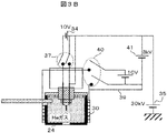
図3Aに本実施例の電界電離イオン源の配線の模式図を示す。フィラメントマウント23の支持棒26には電線33が接続してあり,フィラメント22に電源34により通電することが可能であり,フィラメントからの熱伝導を利用したエミッタティップ21の昇温が可能である。また,この電線にイオンの高電圧電源35が接続されており加速電圧を印加することも可能である。図3Aに示すようにフィラメント22への通電用の配線は銅製の太線33とステンレス製の細線36が接続されている。さらに銅線の太線には切断機構が取り付けられている。図3Bに切断機構37により配線が切断された時の模式図を示す。この切断機構37の一部の材料には温度により変形するバイメタルが使用されており,バイメタルの温度変化により銅線の接続・切断が切り換えられる。
FIG. 3A shows a schematic diagram of the wiring of the field ionization ion source of this example. An
抵抗加熱器への通電用の配線は上記のフィラメント配線と同様に銅製の太線38とステンレス製の細線39が接続されており,銅線の太線には切断機構40が取り付けられている。この切断機構機能の一部の材料には温度により変形するバイメタルが使用されており,バイメタルの温度変化により銅線の接続・切断が切り換えられる。なお,引き出し電極24とエミッタティップ21とは電気的には絶縁されており,さらに,抵抗加熱器の一端と同電位であるため,イオン引き出し電源41により引き出し電極にエミッタティップ21に対して引き出し電圧が印加できる。また,銅線が切断された状態でもステンレス製の細線39により引き出し電極24には引き出し電圧印加できる。
A
次に,図4に本実施例の電界電離イオン源の概略構造図を示す。エミッタティップ21は上部フランジ51より吊り下げる構造となっており,エミッタティップ21を水平直角2方向および上下方向,さらにエミッタティップ先端の角度を調整可能なように可動構造となっている。これに対して,引き出し電極24は真空容器に対して固定である。また,フィラメントマウント23はサファイアベース52によって絶縁されている。本イオン源が真空容器であることはいうまでも無いが,真空排気機構の他に,冷凍機からの冷却伝達機構が存在する。冷凍機4とサファイアベース52は良熱熱伝導体である銅製の冷却伝導棒53によって接続される。しかし,冷凍機は真空容器に固定のため,冷却伝導棒53の先端とサファイアベース52とは変形可能な銅網線54で接続した。これによりエミッタティップ21を可動とするとともに,銅網線54で冷凍機の高振動数の振動伝達を低下させるという効果を奏する。すなわち,高分解能観察が可能なイオン顕微鏡を提供できるという効果を奏する。冷凍機からの振動伝達を低下させるという観点で,引き出し電極24は真空容器に対して固定構造であるが,引き出し電極支持するサファイアベース55と良熱伝導体の冷却伝導棒53の先端との接続も変形可能な銅網線56で接続した。これにより,高分解能観察が可能なイオン顕微鏡を提供できるという効果を奏する。
Next, FIG. 4 shows a schematic structural diagram of the field ionization ion source of this embodiment. The
次に図5を用いて本イオン源の冷却機構について述べる。本装置の特徴は,イオン顕微鏡のイオンビーム照射軸に対して垂直横方向に冷凍機を設置していることである。これによりエミッタティップの可動機構を簡便に構築できるという効果を奏する。なお,本実施例では冷却機構ではパルス管冷凍機71を用いた。パルス管冷凍機は振動の比較的少ない冷凍機であり,エミッタティップの機械的振動を最小にするという特徴を持つ。本パルス管冷凍機は約70Kに冷却される第1冷却ステージ72と5Kに冷却可能な第2冷却ステージ73を持つ。第2冷却ステージは第1冷却ステージ72に接続された輻射シールド74で覆われている。そして,第2冷却ステージは,上で述べたように銅製の冷却伝導棒53を経てサファイアベース52と変形可能な銅網線54で接続されており,最終的にエミッタティップ21を冷却する。上でも述べたが本イオン源では銅網線54で接続することにより機械振動を低減する。
Next, the cooling mechanism of the present ion source will be described with reference to FIG. The feature of this device is that the refrigerator is installed in the horizontal direction perpendicular to the ion beam irradiation axis of the ion microscope. As a result, the movable mechanism of the emitter tip can be easily constructed. In this embodiment, the
またパルス管冷凍機の第1冷却ステージと接続された輻射シールド74は銅製の冷却伝導管57を経て図4の輻射シールド58に接続されている。なお,この冷却伝導管57は上記冷却伝導棒53を覆うようにしてエミッタティップ近傍まで配置される。この輻射シールド58はエミッタティップを含むガス分子イオン化室を囲み,ガス分子イオン化室への熱輻射による熱流入を低減している。さらに図4において,ガス分子イオン化室からイオンビーム引き出し方向に存在してガス分子イオン化室に対向する静電レンズ59の少なくとも一つの電極を輻射シールドと接続する。図4の場合には静電レンズは3枚の電極で構成されており,ガス分子イオン化室に最も近い電極60を輻射シールド58と接続してこれを冷却する。本実施例の冷凍機では第1冷却ステージの冷凍能力は約20Wであり,第2冷却ステージの冷凍能力は約0.5Wである。本実施例では,より大きな冷凍能力を持つ第1冷却ステージに接続された輻射シールドを設けて,これにより,ガス分子イオン化室およびエミッタティップへの熱輻射による熱流入を低減している。これによりエミッタティップの極低温化を実現し,より大電流のイオンビームが得られるガス電界電離イオン源が提供され,ひいては高分解能観察が可能なイオン顕微鏡が提供されるという効果を奏する。
The
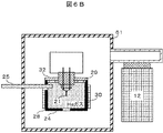
次に,本イオン源の動作について述べる。まず,ガス分子イオン化室天板の開閉弁の操作について図6A、Bを用いて説明する。予め準備したエミッタティップを21取り付けた後に真空容器を真空ポンプ12により排気する。このときには図6Aに示すようにガス分子イオン化室天板のふた32は開いており,ガス分子イオン化室の真空排気系に対するコンダクタンスは,閉じられている場合に比べて大となっておりガス分子イオン化室の特に粗排気が短時間で可能となる効果を奏する。
Next, the operation of this ion source will be described. First, the operation of the opening / closing valve of the top plate of the gas molecule ionization chamber will be described with reference to FIGS. 6A and 6B. After mounting the
真空排気後,ガス分子イオン化室側壁の外側の抵抗加熱器30により,引き出し電極24および側壁28,天板29などを加熱することにより脱ガスする。この時に真空容器61も同時に大気中に配置した別の抵抗加熱器によって加熱することにより真空容器の真空度を向上し,残留ガス濃度を低下する。この操作によりイオン放出電流の時間安定性を向上させるという効果を奏する。本実施例では抵抗加熱器30をガス分子イオン化室の外側に配置した。これにより内部に配置した場合に比べ,抵抗加熱器自身からの脱ガスが無いためガス分子イオン化室をより高真空にできるという効果を奏する。また,本実施例では抵抗加熱器を用いたが,加熱用ランプを配置して,引き出し電極,側壁などを脱ガス処理しても良い。これによれば非接触で加熱できるため引き出し電極の周囲構造を簡単にできかつ,配線に高電圧を印加する必要が無くなり電源を簡単な構造にできるという効果を奏する。また,高温の不活性ガスをガス供給配管から供給して引き出し電極,側壁などを脱ガス処理しても良い。これによればガス加熱機構を接地電位に配置できるため,引き出し電極の周囲構造を簡単にできかつ,配線に高電圧を印加する必要が無くなり電源を簡単な構造にできるという効果を奏する。
After evacuation, the
次に,ガス分子イオン化室および真空容器の加熱を停止し十分な時間を経た後,冷凍機を動作させてエミッタティップ,引き出し電極および輻射シールド等を冷却する。そして,ガス供給配管25によりイオン化ガスであるヘリウムをガス分子イオン化室に導入する。このときには図6Bに示すようにガス分子イオン化室の天板のふた32は,バイメタル合金が変形して閉じた状態になり,ガス分子イオン化室は真空排気系に対してコンダクタンスが小となる。このため,ガス分子イオン化室にヘリウムガスを大量に導入しても,ガス分子イオン化室の外側では真空度が向上できる。
Next, after the heating of the gas molecule ionization chamber and the vacuum container is stopped and a sufficient time has passed, the refrigerator is operated to cool the emitter tip, the extraction electrode, the radiation shield and the like. Then, helium, which is an ionized gas, is introduced into the gas molecule ionization chamber through the
次に,エミッタティップ21と引き出し電極24の間に電圧を印加すると,エミッタティップ先端に強電界が形成される。ヘリウムの多くが,強電界でエミッタティップ面に引っ張られ,最も電界の強いエミッタティップの先端近傍に到達する。そこでヘリウムが電界電離し,引き出し電極の小孔を通してイオンビームを引き出すことができる。ここで,電界強度を調整すると,エミッタティップの先端に存在するナノピラミッド頂点の原子1個近傍でヘリウムイオンが生成される。すなわち非常に限定された領域でイオンが発生するため,単位面積・単位立体角から放出される電流は大きくできるという特徴を持つ。これは試料上で微細径・大電流のイオンビームを得るためには重要な特性である。
Next, when a voltage is applied between the
特に,タングステンにイリジウムなどを蒸着した場合には,先端に1個の原子が存在するナノピラミッド構造も安定してイオンを生成できる。タングステン<111>の先端の3個の原子の場合には,供給されるヘリウムガスが3個の原子に分散される。したがって,ヘリウムガスが1個の原子に集中して供給されるイリジウムのナノピラミッド構造を持つイオン源の方が単位面積・単位立体角から放出される電流は大きくできる。すなわち,タングステンにイリジウムや白金,レニウム,オスミウム,などを蒸着したエミッタティップとすれば,イオン顕微鏡の試料上のビーム径を小さくしたり,電流を増大したりするのに好適となる効果を奏する。 Particularly, when iridium or the like is deposited on tungsten, the nanopyramid structure having one atom at the tip can also stably generate ions. In the case of three atoms at the tip of tungsten <111>, the supplied helium gas is dispersed into the three atoms. Therefore, an ion source having an iridium nanopyramid structure, in which helium gas is concentrated and supplied to one atom, can generate a larger current from a unit area or unit solid angle. That is, an emitter tip in which iridium, platinum, rhenium, osmium, or the like is deposited on tungsten is suitable for reducing the beam diameter on the sample of the ion microscope and increasing the current.
次に,レンズを通過したイオンビーム14は,走査偏向電極301を通過して,さらにアパーチャ板302の微細径の穴を通過して可動のシャッタ303に衝突する。ここで,イオンビームを走査しながら可動のシャッタで発生する二次電子などの二次粒子304を二次粒子検出器305で検出して二次粒子像を得るとエミッタティップのイオン放射パターンが観察できる。そこで,イオン放射パターンを観察しながら,エミッタティップ位置および角度を調整する。また,イオン放射パターンの中で原子1個からのイオンビームがアパーチャを通過するように,イオンビーム軌道もしくはアパーチャ位置を調整することもできる。ピラミッドの先端が3個あるいは6個の原子で構成される場合には,いずれか1個の原子近傍から放出されるイオンを選択してアパーチャを通過するように,イオンビーム軌道もしくはアパーチャ位置を調整することもできる。なお,アパーチャ板302から放出された二次電子などの二次粒子を二次粒子検出器で検出して二次粒子像を得ても同等の効果を得ることができる。特に,可動のシャッタ上に微細な突起を設けてこれの二次粒子像を観察すれば,より明快にパターンが観察できる。なお,本調整の後はシャッタ303を移動させてイオンビームを通過させることは言うまでもない。
Next, the
また,本イオン源では上で述べたようにガス分子イオン化室の外側では真空度が高いためイオンビームが真空中のガスと衝突して中性化する割合が少ないため,大電流のイオンビームを試料に照射できるという効果を奏する。また,高温のヘリウムガス分子が引き出し電極と衝突する個数が少なくなり,エミッタティップおよび引き出し電極の冷却温度を下げることができ,大電流のイオンビームを試料に照射できるという効果を奏する。 Further, in the present ion source, as described above, since the degree of vacuum is high outside the gas molecule ionization chamber, the ion beam collides with the gas in the vacuum and is less likely to be neutralized. The sample can be irradiated. In addition, the number of high-temperature helium gas molecules colliding with the extraction electrode is reduced, the cooling temperature of the emitter tip and the extraction electrode can be lowered, and the sample can be irradiated with a high-current ion beam.
なお,不測の放電現象などによりナノピラミッドが損傷した場合は,エミッタティップを約30分間加熱(1000℃程度)することにより,容易にナノピラミッドを再生することが可能である。 If the nanopyramid is damaged due to an unexpected discharge phenomenon, the nanopyramid can be easily regenerated by heating the emitter tip for about 30 minutes (about 1000 ° C).
なお,本実施例の開閉弁は,イオン源冷却の冷却により他に機械的な機構が無くても自動で開閉が可能になるという利点がある。特に高電圧が印加するのに好適なように簡単な構造にできるという特徴がある。 The on-off valve of the present embodiment has an advantage that it can be automatically opened and closed by cooling the ion source without any other mechanical mechanism. In particular, it has a feature that it can have a simple structure suitable for applying a high voltage.
また,イオンビーム引き出し時には,図3Bに示したようにフィラメントの銅配線および抵抗加熱器の銅配線は切断されている。これは配線の切断機構機能の一部の材料には温度により変形するバイメタルが使用されているため,イオン源冷却によって自動で行われる。なお,各々はステンレス配線により電位を与えられる。これにより,銅配線からの熱流入が無くなり,エミッタティップや引き出し電極の冷却温度を下げることができる。すなわち,イオン源の輝度の向上,イオンビームの大電流化という効果を奏する。これにより大電流のイオンビームが得られるガス電界電離イオン源が提供される,ひいては高分解能観察が可能なイオン顕微鏡が提供されるという効果を奏する。 Further, when the ion beam is extracted, the copper wiring of the filament and the copper wiring of the resistance heater are cut as shown in FIG. 3B. This is done automatically by cooling the ion source because bimetal, which deforms with temperature, is used as part of the material for the wiring cutting mechanism function. Note that each is given a potential by stainless wiring. As a result, the heat inflow from the copper wiring is eliminated, and the cooling temperature of the emitter tip and the extraction electrode can be lowered. That is, the effects of improving the brightness of the ion source and increasing the current of the ion beam are achieved. As a result, a gas electric field ionization ion source capable of obtaining a high-current ion beam is provided, and further, an ion microscope capable of high-resolution observation is provided.
次に図1を用いてイオンビーム照射系の動作について述べる。イオンビーム照射系の動作は,計算処理装置99からの指令により制御される。まず,イオン源のエミッタティップ先端から放出されたイオンビーム14をコンデンサレンズ5,ビーム制限アパーチャ6を通して対物レンズ8で試料ステージ10上の試料9の上に集束する。これにより,微小な点状ビームを試料上で得ることができる。この場合には,電流は数pA程度に少ないがビーム径は1nm以下に小さくできる。この微細なイオンビームをイオンビーム走査電極7により走査させることにより試料から放出される二次電子などの二次粒子検出器11で検出し,これを輝度変調することにより計算処理装置99の画像表示手段上に走査イオン顕微鏡像を得ることができる。すなわち,試料表面の高分解能観察を実現する。
Next, the operation of the ion beam irradiation system will be described with reference to FIG. The operation of the ion beam irradiation system is controlled by a command from the
ここで,本イオン源の特徴はナノピラミッドの先端の原子1個近傍から放出されたイオンを用いることである。すなわち,イオンが放出される領域が狭くイオン光源がナノメータ以下に小さい。このためイオン光源を同じ倍率で試料に集束するか,縮小率を2分の1程度に大きくすると,イオン源の特性を最大限に活かすことができる。従来のガリウム液体金属イオン源の光源の大きさは約50nmと推定されており,試料上で5nmのビーム径を実現するためには大きくても10分の1以下に縮小率を小さくする。この場合にはイオン源のエミッタティップの振動は試料上では10分の1以下に縮小される。例えば,エミッタティップが10nm振動していても試料上では1nm以下であり5nmのビーム径に対する影響は軽微であった。ところが,本実施例によるイオン源では10nmの振動は,2分の1の縮小率では試料上では5nmの振動となり,ビーム径に対して大きくなってしまう。したがって従来の装置ではこの点での配慮が充分でなく,必ずしも良好な試料表面の観察が実現されていなかった。本実施例ではこの振動に対する対策が充分であるため,イオン源の性能を充分発揮した試料表面の高分解能観察が実現されるという効果を奏する。 Here, the feature of this ion source is to use ions emitted from the vicinity of one atom at the tip of the nanopyramid. That is, the area from which ions are emitted is narrow, and the ion light source is as small as a nanometer or less. Therefore, if the ion source is focused on the sample at the same magnification or the reduction rate is increased to about 1/2, the characteristics of the ion source can be maximized. The size of the light source of a conventional gallium liquid metal ion source is estimated to be about 50 nm, and in order to achieve a beam diameter of 5 nm on the sample, the reduction rate should be reduced to less than 1/10 at most. In this case, the vibration of the emitter tip of the ion source is reduced to less than 1/10 on the sample. For example, even if the emitter tip oscillates 10 nm, it is less than 1 nm on the sample, and the effect on the beam diameter of 5 nm is slight. However, in the ion source according to the present embodiment, the vibration of 10 nm becomes a vibration of 5 nm on the sample at a reduction ratio of ½, which is larger than the beam diameter. Therefore, the conventional device did not pay sufficient attention to this point, and it was not always possible to achieve good observation of the sample surface. In this embodiment, since the countermeasure against this vibration is sufficient, there is an effect that high-resolution observation of the sample surface can be realized, which shows the performance of the ion source sufficiently.
なお,本電界電離イオン源の引き出し電極は真空容器に対して固定されているが,エミッタティップマウントが銅網線で接続されることにより,エミッタティップは引き出し電極に対して可動となる。これにより,エミッタティップの引き出し電極の小孔に対する位置調整や光学系に対する軸調整が可能になり,より微細なビームを形成することが可能になるという効果を奏するということは言うまでも無い。 Although the extraction electrode of the present field ionization ion source is fixed to the vacuum container, the emitter tip is movable with respect to the extraction electrode by connecting the emitter tip mount with a copper mesh wire. As a result, it goes without saying that the position adjustment of the extraction electrode of the emitter tip with respect to the small hole and the axis adjustment with respect to the optical system can be performed, and a finer beam can be formed.
また,パルス管冷凍機はGM型でもスターリング型のいずれでも良い。また,本実施例では,2つの冷却ステージを持つ冷凍機について説明したが,単一の冷却ステージを持つものでも良く,本発明は冷却ステージの数によって限定されるものではない。 The pulse tube refrigerator may be either a GM type or a Stirling type. Further, although the refrigerator having two cooling stages has been described in the present embodiment, a refrigerator having a single cooling stage may be used, and the present invention is not limited by the number of cooling stages.
以上,本実施例によれば,真空粗引き時のコンダクタンス増大化とイオンの大電流化の観点からの引き出し電極穴の小径化との両立ができ,大電流のイオンビームが得られるガス電解電離イオン源が提供される。 As described above, according to the present embodiment, it is possible to achieve both the increase in conductance at the time of rough vacuuming and the reduction in the diameter of the extraction electrode hole from the viewpoint of increasing the current of ions, and to obtain a large current ion beam by gas electrolytic ionization. An ion source is provided.
また,ガス分子イオン化室の高真空化が実現し,高安定なイオン放出が可能なガス電解電離イオン源が提供される。 Further, a high vacuum of the gas molecule ionization chamber is realized, and a gas electrolytic ionization ion source capable of highly stable ion release is provided.
また,エミッタの極低温化が実現し大電流のイオンビームが得られるガス電解電離イオン源が提供される。また,機械振動の低減が実現し高分解能観察が可能なガス電解電離イオン源およびイオン顕微鏡が提供される。 In addition, a gas electrolytic ionization ion source that can achieve a cryogenic temperature of the emitter and obtain a high-current ion beam is provided. In addition, a gas electrolytic ionization ion source and ion microscope capable of reducing mechanical vibration and enabling high-resolution observation are provided.
実施例1では振動の比較的少ないパルス管冷凍機を用いたが,イオンビームのビーム径を最小にするためには必ずしも満足できない場合がある。実施例2ではパルス管冷凍機の代わりにGM型冷凍機とヘリウムガスポットを組み合わせた冷凍機を用いる。 In Example 1, a pulse tube refrigerator with comparatively little vibration was used, but it may not always be satisfactory to minimize the beam diameter of the ion beam. In Example 2, instead of the pulse tube refrigerator, a refrigerator in which a GM type refrigerator and a helium gas spot were combined was used.
本GM型冷凍機は,約50Kに冷却される第1冷却ステージと4Kに冷却可能な第2冷却ステージを持つ。これらの冷却ステージは密封型のポットによって覆われている。そしてポットのなかはヘリウムガスで満たされている。すなわち,GM型冷凍機は,ヘリウムガスを冷却し,ヘリウムガスがポット外壁を冷却する。この構造によりポットの先端は約6Kまで冷却され,第1冷却ステージ近傍は約70Kに冷却されている。本冷凍システムでは,GM型冷凍機が振動しても,ヘリウムガスが中間に存在するため機械振動は減衰して伝達される。すなわち,ヘリウムガスポットの機械振動はGM型冷凍機の機械振動に比べて低減するという効果を奏する。ヘリウムガスポットは,実施例1で述べたように銅製の冷却伝導棒を経てエミッタティップマウントに銅網線で接続されており,エミッタティップを冷却する。実施例1でも述べたが銅網線で接続することによりさらに機械振動を低減する。本冷却システムを用いたガス電界電離イオン源はエミッタティップの機械的振動をさらに低減できるという特徴を持つ。 This GM refrigerator has a first cooling stage cooled to about 50K and a second cooling stage capable of cooling to 4K. These cooling stages are covered by a sealed pot. And the pot is filled with helium gas. That is, the GM type refrigerator cools the helium gas, and the helium gas cools the outer wall of the pot. With this structure, the tip of the pot is cooled to about 6K, and the vicinity of the first cooling stage is cooled to about 70K. In this refrigeration system, even if the GM type refrigerator vibrates, mechanical vibration is attenuated and transmitted because helium gas exists in the middle. That is, the mechanical vibration of the helium gas spot is reduced as compared with the mechanical vibration of the GM type refrigerator. As described in the first embodiment, the helium gas spot is connected to the emitter tip mount by a copper mesh wire via the cooling conducting rod made of copper, and cools the emitter tip. As described in the first embodiment, the mechanical vibration is further reduced by connecting with the copper mesh wire. The gas field ionization ion source using this cooling system has a feature that the mechanical vibration of the emitter tip can be further reduced.
以上,本実施例によれば,機械振動の低減が実現し高分解能観察が可能なガス電解電離イオン源およびイオン顕微鏡が提供される。 As described above, according to this embodiment, a gas electrolytic ionization ion source and an ion microscope capable of reducing mechanical vibration and enabling high-resolution observation are provided.
実施例1および2では冷却機を用いた。しかし,冷却機は本質的には機械的振動を発生し,エミッタティップに伝達しやすい。エミッタティップの振動は荷電粒子顕微鏡においてビームの試料照射点をも振動させ,顕微鏡分解能を劣化させる。実施例3では,冷却剤として固体窒素(真空中の凝固温度は約51K)を用いた。 In Examples 1 and 2, a cooler was used. However, the cooler essentially generates mechanical vibration and is easily transmitted to the emitter tip. Vibration of the emitter tip also vibrates the sample irradiation point of the beam in the charged particle microscope, degrading the microscope resolution. In Example 3, solid nitrogen (solidification temperature in vacuum is about 51 K) was used as the coolant.
図7本実施例のガス電界電離イオン源の構成図を示す。本イオン源では実施例1で冷凍機を配置した場所に固体窒素チャンバを配置する。個体窒素チャンバ81は真空容器であり,内部に固体窒素タンク82が存在する。固体窒素タンク82には実施例1と同様に銅製の伝達棒53が接続されている。本イオン源では実施例1で述べた輻射シールド57も固体窒素タンク82に接続される。固体窒素タンク82には,最初に液体窒素を導入し,その後,固体窒素タンク内を真空排気口83から真空引きする。これにより,液体窒素は固体窒素84に凝固する。真空排気環境の固体窒素は,エミッタティップ,引き出し電極および輻射シールドからの熱流入により昇華して,それらを冷却する。この冷却方法においては,液体窒素が沸騰する際の発泡による振動は生じない。すなわち,本実施例のイオン源によれば,機械振動の低減が実現し高分解能観察が可能なガス電解電離イオン源およびイオン顕微鏡が提供される。
7 is a block diagram of the gas field ionization ion source of the present embodiment. In this ion source, the solid nitrogen chamber is arranged at the place where the refrigerator is arranged in the first embodiment. The
次に,輻射シールドの冷却剤として固体窒素を採用し,エミッタティップの冷却剤として液体ヘリウムを用いた例について述べる。図8に本実施例のガス電界電離イオン源の模式構成図を示す。本イオン源ではエミッタティップ21は液体ヘリウムタンク85と直結して冷却する。そして,固体窒素83はエミッタティップ21およびガス分子イオン化室周囲および液体ヘリウムタンク85を輻射シールドする。固体窒素タンク83には上記と同様に銅製の伝達棒57が接続されている。固体窒素の作製方法は上で述べた方法と同じである。本実施例では固体窒素は,輻射シールドを冷却するが,同様に発泡による振動は生じない。また,液体へリウムは別途液体ヘリウムデュアとトランスファーチューブ(図示していない)で接続され,その振動は最小化されている。すなわち,本実施例のイオン源によれば,機械振動の低減が実現し高分解能観察が可能なガス電解電離イオン源およびイオン顕微鏡が提供される。
Next, we will describe an example in which solid nitrogen is used as the coolant for the radiation shield and liquid helium is used as the coolant for the emitter tip. FIG. 8 shows a schematic configuration diagram of the gas field ionization ion source of this example. In this ion source, the
また,固体窒素を冷却するのに冷凍機を固体窒素タンク中に配置して,高分解能が必要な観察時間中のみ冷凍機の動作を停止しても良い。この場合には固体窒素の消費量を低減できるという効果を奏する。また,冷凍機の動作を止めても固体窒素が融解または蒸発に伴う潜熱によってティップ温度を低温に保てるという効果を奏する。すなわち,本実施例のイオン源によれば,機械振動の低減が実現し高分解能観察が可能なガス電解電離イオン源およびイオン顕微鏡が提供される。なお,本実施例では窒素を用いたが他に,ネオン,酸素,アルゴン,メタン,水素なども利用できる。特に固体ネオンを用いた場合には,ヘリウムイオンビームを大電流化するのに好適な低温を実現できるという効果を奏する。 Further, a refrigerator may be placed in the solid nitrogen tank to cool the solid nitrogen, and the operation of the refrigerator may be stopped only during an observation time period requiring high resolution. In this case, it is possible to reduce the consumption of solid nitrogen. In addition, even if the operation of the refrigerator is stopped, the tip temperature can be kept low due to the latent heat of solid nitrogen melting or vaporizing. That is, according to the ion source of the present embodiment, a gas electrolytic ionization ion source and an ion microscope capable of realizing mechanical vibration reduction and high resolution observation are provided. In this embodiment, nitrogen is used, but neon, oxygen, argon, methane, hydrogen, etc. can also be used. In particular, when solid neon is used, there is an effect that it is possible to realize a low temperature suitable for increasing the current of the helium ion beam.
図9に,実施例4に係るイオンビーム顕微鏡と電子ビーム顕微鏡の複合装置の構成を示す。また,図10Aに,本実施例に係るイオンビーム顕微鏡と電子ビーム顕微鏡の複合装置の構成の上面図示す。図10Bに,同じく側面図を示す。 FIG. 9 shows the configuration of the combined apparatus of the ion beam microscope and the electron beam microscope according to the fourth embodiment. Further, FIG. 10A shows a top view of the configuration of the combined apparatus of the ion beam microscope and the electron beam microscope according to this embodiment. A side view is also shown in FIG. 10B.
本イオンビーム顕微鏡の構成および動作は実施例1とほぼ同じである。本装置では真空試料室に走査電子顕微鏡が取り付けられている。本走査電子顕微鏡は,電子銃101,電子レンズ103,電子ビーム走査偏向器104及びそれらを格納する電子ビームカラム105等で構成される。
The configuration and operation of this ion beam microscope are almost the same as in the first embodiment. In this device, a scanning electron microscope is attached to the vacuum sample chamber. The scanning electron microscope is composed of an
真空試料室内3には,試料9を載置する試料ステージ10,二次粒子検出器11のほかにX線検出器106が配置されている。本試料ステージには傾斜機能を備えており試料表面を電子ビーム102に垂直にすることも可能である。本装置では,ヘリウムもしくは水素イオンビームと,電子ビームが試料上のほぼ同じ位置を照射可能である。
In the
次に,走査電子顕微鏡の動作手順について説明する。電子銃101から放出される電子ビーム102を電子レンズ103により集束して試料9に照射する。このとき電子ビーム102を電子ビーム走査偏向器104により走査しながら試料断面に照射し,試料断面から放出される二次電子を二次粒子検出器11で検出して,その強度を画像の輝度に変換すれば試料を観察することができる。本電子ビーム照射位置はイオンビーム照射位置と同じくなるように予め調整しておく。これは,まず,イオン顕微鏡像を計算処理装置99に記憶させておき,次に走査電子顕微鏡像を観察しながら,記憶されたイオン顕微鏡像での特徴点が走査電子顕微鏡像で観察される同じ特徴点が同じ位置に表示されるように,電子ビーム走査偏向器104を制御する直流バイアス電流を調整すれば良い。あるいは,再びイオン顕微鏡により試料観察をしながら,イオン顕微鏡の走査偏向電極7の直流制御電圧を調整すれば良い。ここでは,電子ビーム照射位置はイオンビーム照射位置を一致させるのに走査偏向器を用いたが,別に調整用の偏向器を備えても良い。この場合には偏向器の直流分のみを制御する偏向制御になるため,交流を制御する走査偏向器の電源よりもノイズが低い電源を作製するのが容易になるという効果を奏する。
Next, the operation procedure of the scanning electron microscope will be described. The
このようにすると,試料ステージ10を移動することなく,試料のヘリウムイオンビーム走査二次電子像および電子ビーム走査二次電子像を得ることができる。両者は制御装置99の画像表示手段上に並べて表示される。両者は概略同等の表面情報をもたらすが,イオンビーム励起による二次電子イールドと電子ビーム励起の二次電子イールドが異なるため詳細には別の情報をもたらし,試料のより詳細な解析が可能になる。
By doing so, a helium ion beam scanning secondary electron image and an electron beam scanning secondary electron image of the sample can be obtained without moving the
本装置の特徴は,図10Bに示すように,イオン顕微鏡のイオンビーム照射軸1003が,装置の設置面すなわち図10AのXY面に対して概略垂直であり,電子ビーム照射軸1004が装置の設置面に対して傾斜方向に配置されたことである。これは,すでに述べた本イオン顕微鏡の特徴に係わる。すなわち,本イオン源の特徴はナノピラミッドの先端の原子1個近傍から放出されたイオンを用いることである。すなわち,イオンが放出される領域が狭くイオン光源がナノメータ以下に小さい。このためイオン光源を同じ倍率で試料に集束するか,縮小率を2分の1程度に大きくすると,イオン源の特性を最大限に活かすことができる。
10B, the ion
本イオン顕微鏡の高分解能観察ができるという特長を活かすためには,試料の振動,電界電離イオン源,およびイオン顕微鏡のカラムの振動が課題になる。 In order to take advantage of the high-resolution observation of this ion microscope, the vibration of the sample, the field ionization ion source, and the vibration of the ion microscope column are important issues.
振動シミュレーションおよび実験評価した結果,イオン顕微鏡のイオンビーム照射軸が,装置の設置面に対して概略垂直で試料が水平に載置された方が,高分解能の観察ができることがわかった。特に,傾斜された電子銃はイオン源よりも振動が大きいことがわかったが,走査電子顕微鏡では電子の光源径を試料上に集束する縮小率がイオン顕微鏡よりも小さく,電子銃の振動の影響がイオン顕微鏡よりも小さいことがわかった。これらは本装置のようにナノピラミッド先端の原子1個から放出されたイオンビームを用い,1nm以下の分解能が得られるイオン顕微鏡であることから新しく発生した検討課題であり,本実施例ではこの振動に対する対策が充分であるため,イオン源の性能を充分発揮した試料表面の高分解能観察が実現されるという効果を奏する。 As a result of vibration simulation and experimental evaluation, it was found that high-resolution observation is possible when the ion beam irradiation axis of the ion microscope is placed substantially perpendicular to the installation surface of the device and the sample is placed horizontally. In particular, it was found that the tilted electron gun vibrates more than the ion source, but the scanning electron microscope has a smaller reduction rate for focusing the electron source diameter on the sample than the ion microscope, and the influence of the vibration of the electron gun is large. Was smaller than the ion microscope. Since these are ion microscopes that use an ion beam emitted from one atom at the tip of the nanopyramid as in this device and can obtain a resolution of 1 nm or less, they are new research subjects, and this oscillation is caused in this example. Since the countermeasures against the above are sufficient, it is possible to realize high-resolution observation of the sample surface, which shows the performance of the ion source sufficiently.
また,試料から放出されるX線をX線検出器106で検出すれば試料表面の元素分析が可能である。特に,イオン顕微鏡ではイオンの加速電圧が数10kVではX線がほとんど放出されず元素分析が困難であった。本装置によれば,イオンビームによる超高分解能観察と元素分析が同時に実施可能となる効果を奏する。特に,ヘリウムイオンビーム走査二次電子像,電子ビーム走査二次電子像,X線分析像のいずれか2つがほぼ同時に制御装置99の画像表示手段上に並べて表示されれば,試料のより詳細な解析が可能になる。
Further, if the X-rays emitted from the sample are detected by the
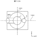
また,本装置では真空試料室を,電子ビーム照射系カラム取り付け方向を中心に電子ビーム照射系カラム取り付け方向とそうでない方向に2分した時,すなわち,図10Aで試料室の中心線1001によって2分した時,真空試料室のX線検出器の取り付け位置を,電子ビーム照射系カラム取り付け方向内,すなわち図10Aで中心線1001よりも右側に収めたことが特徴である。このように配置すれば,試料ステージを電子ビームカラム方向に傾斜して,電子ビームを試料に垂直に照射して観察してもX線分析が可能になるという効果を奏する。
Further, in the present apparatus, when the vacuum sample chamber is divided into two, with the electron beam irradiation system column mounting direction as the center and in the electron beam irradiation system column mounting direction and in the other direction, that is, in FIG. When divided, the feature is that the mounting position of the X-ray detector in the vacuum sample chamber is set within the mounting direction of the electron beam irradiation system column, that is, on the right side of the
なお,本実施例では,ヘリウムもしくは水素イオンビームと,電子ビームが試料上のほぼ同じ位置を照射可能なように電子ビーム照射系カラムとイオン顕微鏡の照射系カラムを配置したが,イオン顕微鏡のイオンビーム照射軸と電子ビーム照射軸が試料上では概略交わることなく離れた位置に配置すれば,各々の対物レンズがお互い機械的な干渉がなくなるため試料に近づけることができ,各々の顕微鏡の分解能を向上させることができるという効果を奏する。 In this embodiment, the electron beam irradiation system column and the ion microscope irradiation system column are arranged so that the helium or hydrogen ion beam and the electron beam can irradiate the same position on the sample. If the beam irradiation axis and the electron beam irradiation axis are arranged at positions apart from each other without substantially intersecting with each other on the sample, the objective lenses can be brought close to the sample because mechanical interference with each other is eliminated, and the resolution of each microscope can be increased. There is an effect that it can be improved.
また,本装置の特徴は,イオン顕微鏡のイオンビーム照射軸に対して垂直横方向に冷凍機を設置し,その方向が,電子顕微鏡の照射軸方向1004を図10AのXY面上に投影した中心軸1002上で中心軸1001よりも右側とは異なる方向であることを特徴とする。すなわち,図10Aの中心軸1002上で中心軸1001よりも右側には冷凍機を配置しない。図10Aに示すように反対方向である左側に配置するのが最も好ましい。これも冷凍機の振動が走査電子顕微鏡の分解能に影響することを考慮して振動シミュレーションおよび実験評価した結果得られた結果であるが,冷凍機を,走査電子顕微鏡の照射軸方向1004を図10AのXY面上に投影した中心軸1002上で中心軸1001よりも右側に冷凍機を配置すると,振動の影響で走査電子顕微鏡の観察分解能が劣化することがわかったからである。
Further, the feature of this device is that the refrigerator is installed in a horizontal direction perpendicular to the ion beam irradiation axis of the ion microscope, and the direction is the center of the
以上,本実施例によれば,イオン顕微鏡による試料観察,電子顕微鏡による試料観察および元素分析が1台の装置で可能な装置,欠陥や異物などを観察・解析するのに好適な装置解析装置,および検査装置が提供される。 As described above, according to the present embodiment, a device capable of observing a sample with an ion microscope, a sample with an electron microscope, and an elemental analysis with a single device, a device analysis device suitable for observing and analyzing defects and foreign matters, And an inspection device is provided.
図11に,実施例5に係るイオンビーム顕微鏡とイオンビーム加工装置との複合装置の構成を示す。また,図12Aに,本実施例に係るイオンビーム顕微鏡とイオンビーム加工装置の複合装置の構成の上面図示す。図10Bに,同じく側面図を示す。 FIG. 11 shows the configuration of a combined device of an ion beam microscope and an ion beam processing device according to the fifth embodiment. Further, FIG. 12A shows a top view of the configuration of the combined apparatus of the ion beam microscope and the ion beam processing apparatus according to this embodiment. A side view is also shown in FIG. 10B.
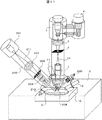
本イオンビーム顕微鏡の構成および動作は実施例1とほぼ同じである。なお,冷凍機4の配置に特徴があり,図12Bに示すように冷凍機4はイオン顕微鏡のイオンビーム照射軸1003に対して垂直横方向に設置した。次に,イオンビーム顕微鏡と複合するイオンビーム加工装置は,ガリウムを放出する液体金属イオン源201,コンデンサレンズ202,対物レンズ203,イオンビーム走査偏向器204,ステンシルマスク205及びこれらを格納する加工用イオンビーム照射系カラム206などから構成される。イオン顕微鏡カラムおよび加工用イオンビーム照射系カラムの下部には,真空試料室3が配置されており,真空試料室内には,試料9を載置する第1の試料ステージ10,二次粒子検出器11,デポガス源207などが格納されている。また,本装置には,第1試料ステージ上の試料からイオンビーム加工を用いて摘出した試料片を搬送するためのプローブ208と,プローブを駆動するマニュピレータ209,微小試料片を載せる第2の試料ステージ210を備える。本実施例では,ヘリウムもしくは水素イオンビームと,ガリウムイオンビームが試料上のほぼ同じ位置を照射可能なようにガリウムイオンビーム照射系カラムとヘリウムもしくは水素イオンビーム照射系カラムを配置した。なお,イオンビーム照射系カラム206内部も真空に維持されているのは言うまでもない。
The configuration and operation of this ion beam microscope are almost the same as in the first embodiment. It should be noted that the
ここで,第2試料ステージ210は,傾斜軸周りに回転することによりイオンビームの試料片への照射角度を可変できる傾斜機能を持つ。また,この第2試料ステージ210は第1の試料ステー10上に配置されているため,第1の試料載置面内の直行2方向への直線移動,試料載置面に垂直方向への直線移動,および試料載置面内回転は,第1の試料ステージ10を移動・回転させることによって可能になる。
Here, the
次に,本装置の動作について述べる。まず,液体金属イオン源201からガリウムイオンビーム211を引き出す。そして,このイオンビームをコンデンサレンズ202により対物レンズ中心近傍に集束させる。そしてイオンビームは矩形の穴を有するステンシルマスク205を通過する。対物レンズ203はステンシルマスク205を試料の上に投影する条件で制御する。このようにすると,試料上には矩形の成型イオンビームが照射される。この成型イオンビームを照射し続けると試料に矩形の穴が形成される。
Next, the operation of this device will be described. First, the
本装置では,イオン顕微鏡による観察機能は,試料の欠陥や異物の断面を観察することや,電子顕微鏡用薄膜試料の断面を観察して,加工終点を把握することなどにも用いる。 In this equipment, the observation function by the ion microscope is also used for observing the cross section of defects and foreign matters of the sample, and observing the cross section of the thin film sample for electron microscope to grasp the processing end point.
本装置では,イオンビーム加工装置により試料から微小試料を摘出して,これをプローブに固定してマニュピレータを駆使して第2のステージ上に載せることが可能になる。これを,イオン顕微鏡により観察することができる。すなわち,同一装置内で試料内部の構造を従来の電子ビームによる観察に比べて高分解能で観察することができるという効果を奏する。 In this device, it becomes possible to extract a minute sample from the sample by the ion beam processing device, fix it on the probe, and place it on the second stage by making full use of the manipulator. This can be observed with an ion microscope. That is, there is an effect that the structure inside the sample can be observed with higher resolution in the same apparatus as compared with the conventional observation using the electron beam.
特に,従来の電子ビーム走査顕微鏡では,電子レンズの磁場がガリウムの同位体を質量分離するため,ガリウムイオンビームの軌道が2本に分離するという課題があった。これにより従来のFIB-SEM装置ではガリウムの加工が高精度に行えない,あるいはガリウムイオンビームによるSIM像が二重になるという問題があった。本実施例のイオン顕微鏡では磁場レンズでは無く静電型のレンズを用いるためこのような問題を解決して高精度な加工と高分解の像観察が可能になるという効果を奏する。 In particular, in the conventional electron beam scanning microscope, the magnetic field of the electron lens separates the isotopes of gallium by mass, so that there is a problem that the orbits of the gallium ion beam are separated into two. As a result, the conventional FIB-SEM system has a problem that gallium cannot be processed with high precision, or the SIM image by the gallium ion beam becomes double. Since the ion microscope of this embodiment uses the electrostatic type lens instead of the magnetic field lens, it has an effect of solving such a problem and enabling high-precision processing and high-resolution image observation.
なお,以上の実施例ではイオン顕微鏡はイオンビームを走査して二次電子を検出したが,薄膜試料を透過したイオンを検出しても良い。また薄膜裏面で発生した二次電子を検出すれば試料裏面の表面観察が可能になる。 Although the ion microscope scans the ion beam to detect the secondary electrons in the above embodiments, the ions that have passed through the thin film sample may be detected. Also, by detecting the secondary electrons generated on the back surface of the thin film, the surface of the back surface of the sample can be observed.
本装置の特徴は,図12Bに示すようにイオン顕微鏡のイオンビーム照射軸1003が,装置の設置面すなわち図12AのXY面に対して概略垂直であり,ガリウム集束イオンビームのイオンビーム照射軸1005が装置の設置面に対して傾斜方向に配置されたことである。これは,本イオン顕微鏡の高分解能な特長を活かすためには,試料の振動,電界電離イオン源,およびイオン顕微鏡のイオンビーム照射系カラムの振動が課題になる。すなわち,本イオン源の特徴はナノピラミッドの先端の原子1個近傍から放出されたイオンを用いることである。すなわち,イオンが放出される領域が狭くイオン光源がナノメータ以下に小さい。このためイオン光源を同じ倍率で試料に集束するか,縮小率を2分の1程度に大きくすると,イオン源の特性を最大限に活かすことができる。
The apparatus is characterized in that the ion
本イオン顕微鏡の高分解能観察ができるという特長を活かすためには,試料の振動,電界電離イオン源,およびイオン顕微鏡のカラムの振動が課題になる。 In order to take advantage of the high-resolution observation of this ion microscope, the vibration of the sample, the field ionization ion source, and the vibration of the ion microscope column are important issues.
振動シミュレーションおよび実験評価した結果,イオン顕微鏡のイオンビーム照射軸が,装置の設置面に対して概略垂直で試料が水平に載置された方が,高分解能の観察ができることがわかった。特に,傾斜されたガリウム液体金属イオン源は電界電離イオン源よりも振動が大きいことがわかったが,既に述べたようにガリウム液体金属イオン源ではイオンの光源径を試料上に集束する縮小率がイオン顕微鏡よりも小さく,ガリウム液体金属イオン源の振動の影響がイオン顕微鏡よりも小さいことがわかった。これらは本装置のようにナノピラミッド先端の原子1個から放出されたイオンビームを用い,1nm以下の分解能が得られるイオン顕微鏡であることから新しく発生した検討課題であり,本発明ではこの振動に対する対策が充分であるため,イオン源の性能を充分発揮した試料表面の高分解能観察が実現されるという効果を奏する。 As a result of vibration simulation and experimental evaluation, it was found that high-resolution observation is possible when the ion beam irradiation axis of the ion microscope is placed substantially perpendicular to the installation surface of the device and the sample is placed horizontally. In particular, it was found that the tilted gallium liquid metal ion source has a larger vibration than the field ionization ion source. As described above, the gallium liquid metal ion source has a reduction ratio for focusing the light source diameter of the ions on the sample. It was found that the effect of vibration of the gallium liquid metal ion source is smaller than that of the ion microscope and smaller than that of the ion microscope. Since these are ion microscopes that use an ion beam emitted from one atom at the tip of the nanopyramid as in the present device and can obtain a resolution of 1 nm or less, they are new research subjects. Since sufficient countermeasures are taken, there is an effect that high-resolution observation of the sample surface can be realized while exhibiting the performance of the ion source.
また,本装置の特徴は,イオン顕微鏡のイオンビーム照射軸に対して垂直横方向に冷凍機を設置し,その方向が,ガリウム集束イオンビームの照射軸方向1005を図12AのXY面上に投影した中心軸1002上で中心軸1001よりも左側とは異なる方向であることを特徴とする。すなわち,図12Aの中心軸1002上で中心軸1001よりも左側には冷凍機を配置しない。図12Aに示すように反対方向である右側に配置するのが最も好ましい。これも冷凍機の振動がガリウム集束イオンビーム加工装置の分解能に影響することを考慮して振動シミュレーションおよび実験評価した結果得られた結果であるが,冷凍機を,ガリウム集束イオンビームの照射軸方向1005を図12AのXY面上に投影した中心軸1002上で中心軸1001よりも左側に冷凍機を配置すると,振動の影響でガリウム集束イオンビーム加工精度性能が劣化することがわかったからである。
The feature of this device is that the refrigerator is installed in a horizontal direction perpendicular to the ion beam irradiation axis of the ion microscope, and that direction projects the
なお,本実施例ではガリウム液体金属イオン源を用いたが,アルゴンやキセノンなどの不活性ガスや酸素,窒素などのガスイオンを発生させるプラズマイオン源でも良い。その場合には試料をガリウムでは汚染しないという効果を奏する。 Although a gallium liquid metal ion source is used in this embodiment, a plasma ion source that generates an inert gas such as argon or xenon or gas ions such as oxygen or nitrogen may be used. In that case, there is an effect that the sample is not contaminated with gallium.
また,ガスイオンビームをシリコンウェーハに照射して微小試料を摘出した後に形成された穴に対して,デポジションガスを導入しながらガスイオンビームを照射して穴埋めするイオンビーム加工装置において,デポジションによって形成された表面の3次元形状をイオン顕微鏡のイオンビームによって計測して,その計測結果を基にして不活性ガスイオンビームを制御すれば,穴の表面を平坦にすることが可能であることがわかった。すなわち,加工したシリコンウェーハを半導体デバイスのプロセスに戻しても製造に悪影響を与えないという効果を奏する。なお,この場合には必ずしもイオン顕微鏡のイオンビームである必要は無く電子顕微鏡の電子ビームであっても同様な効果を奏する。3次元形状を測定する方法は,試料を傾斜させるか,あるいはイオンビームまたは電子ビームを傾斜させて試料に照射して得られた2枚の画像の視差によって計測できる。あるいは試料高さによる焦点の違いを利用しても良い。得られた試料の3次元形状に対して,これを平坦にするようにイオンビームを制御する方法は走査制御において照射位置および照射時間を場所ごとに適切に設定すれば良い。例えば,平坦に比べて低い場所にはより長い時間イオンビームを照射すれば良い。以上,本発明によればイオンビームで加工した穴を平坦に埋めることができ,加工したウェーハを製造プロセスラインに戻すのに好適なイオンビーム加工装置が提供される。 In addition, an ion beam processing apparatus that irradiates a gas ion beam to a hole formed after a silicon wafer is irradiated with a gas ion beam to extract a minute sample and irradiates the gas ion beam while introducing a deposition gas, It is possible to make the surface of the hole flat by measuring the three-dimensional shape of the surface formed by the ion beam of the ion microscope and controlling the inert gas ion beam based on the measurement result. I understood. That is, even if the processed silicon wafer is returned to the process of the semiconductor device, the manufacturing is not adversely affected. In this case, the ion beam of the ion microscope is not necessarily required, and the same effect can be obtained even with the electron beam of the electron microscope. The three-dimensional shape can be measured by tilting the sample or tilting the ion beam or the electron beam to irradiate the sample and measuring the parallax of two images. Alternatively, the difference in focus depending on the sample height may be used. With respect to the method of controlling the ion beam so as to flatten the three-dimensional shape of the obtained sample, the irradiation position and the irradiation time may be appropriately set for each place in the scanning control. For example, an ion beam may be irradiated for a longer time on a place lower than that on a flat surface. As described above, according to the present invention, it is possible to provide an ion beam processing apparatus that can fill a hole processed by an ion beam evenly and is suitable for returning a processed wafer to a manufacturing process line.
また,冷凍機4にヘリウムを送るコンプレッサ1100の音が電界電離イオン源を振動させてその分解能を劣化させることを突き止めた。このため,図13のように冷凍機のコンプレッサと電界電離イオン源を空間的に分離する装置カバー1101を設けた。これにより,冷凍機のコンプレッサの音を遮蔽して,振動の影響がさらに低減し,高分解能観察が可能なガス電解電離イオン源およびイオン顕微鏡が提供される。
It was also found that the sound of the
また,以上の実施例では電界電離イオン源を真空排気する真空ポンプとしてターボ分子ポンプを用いたが,非蒸発ゲッタポンプとイオンポンプはたはノーブルポンプにすれば,振動の影響がさらに低減し,高分解能観察が可能なガス電解電離イオン源およびイオン顕微鏡が提供されることがわかかった。ここで非蒸発ゲッタポンプは,加熱による活性化でガス吸着する合金を用いて構成された真空ポンプである。電界電離イオン源のイオン化ガスとしてヘリウム用いる場合には,ヘリウムが真空容器内に比較的大量に存在するが,非蒸発ゲッタポンプはヘリウムをほとんど排気しないため,ゲッタ表面が吸着ガス分子で飽和することが無く非蒸発ゲッタポンプの動作時間を長くすることができるという効果を奏する。これはヘリウムイオン顕微鏡と非蒸発ゲッタポンプを組み合わせて生じる効果である。また,真空容器中の不純物ガスが減少することによりイオン放出電流が安定するという効果も奏する。ただし,非蒸発ゲッタポンプは大きな排気速度でヘリウム以外の残留ガスを排気するが,これだけではヘリウムがイオン源に停留して真空度が劣化してイオン源が動作しない。そこでイオンポンプまたは不活性ガスの排気速度が大きいノーブルポンプを組み合わせることで真空を維持する。イオンポンプまたはノーブルポンプのみであれば排気速度を上げるために大型のポンプが必要になり構造が複雑となる。今回,非蒸発ゲッタポンプとイオンポンプはたはノーブルポンプを組合せることによりコンパクトで低コストのイオン源を実現できた。従来は機械振動への配慮が足らずイオン顕微鏡の性能が十分には得られなかったが,本発明により,機械振動の低減が実現し高分解能観察が可能なガス電解電離イオン源およびイオン顕微鏡が提供される。 In addition, although the turbo molecular pump is used as a vacuum pump for evacuating the field ionization ion source in the above-described embodiments, if a non-evaporable getter pump and an ion pump or a noble pump are used, the influence of vibration is further reduced and the It was found that a gas electrolytic ionization ion source and an ion microscope capable of resolution observation are provided. Here, the non-evaporable getter pump is a vacuum pump made of an alloy that adsorbs gas when activated by heating. When helium is used as the ionization gas of the field ionization ion source, helium is present in a relatively large amount in the vacuum container, but the non-evaporable getter pump hardly exhausts helium, so the getter surface may be saturated with adsorbed gas molecules. There is an effect that the operation time of the non-evaporable getter pump can be lengthened. This is an effect produced by combining a helium ion microscope and a non-evaporable getter pump. Further, the ion emission current is stabilized by reducing the impurity gas in the vacuum container. However, the non-evaporable getter pump exhausts residual gas other than helium at a high pumping speed, but with this alone, helium remains in the ion source, the degree of vacuum deteriorates, and the ion source does not operate. Therefore, the vacuum is maintained by combining an ion pump or a noble pump with a high exhaust rate of the inert gas. If only an ion pump or a noble pump is used, a large pump is required to increase the pumping speed, which complicates the structure. This time, we have realized a compact and low-cost ion source by combining a non-evaporable getter pump, an ion pump, and a noble pump. Conventionally, the consideration of mechanical vibration was insufficient and the performance of the ion microscope was not sufficiently obtained, but the present invention provides a gas electrolytic ionization ion source and an ion microscope capable of reducing mechanical vibration and enabling high-resolution observation. To be done.
以上,本発明によれば,真空粗引き時のコンダクタンス増大化とイオンの大電流化の観点からの引き出し電極穴の小径化との両立ができ,大電流のイオンビームが得られるガス電解電離イオン源が提供される。 As described above, according to the present invention, both the increase in conductance during rough vacuuming and the reduction in the diameter of the extraction electrode hole from the viewpoint of increasing the current of ions can be achieved at the same time, and a gas electrolytic ionized ion that can obtain a large current ion beam can be obtained. Source is provided.
また,非蒸発ゲッタポンプをヘリウムガス供給配管途中に配置すると供給するガスの中に不純物ガスが減少することにより,イオン放出電流が安定するガス電解電離イオン源およびイオン顕微鏡が提供される。また,ガス分子イオン化室の高真空化が実現し,高安定なイオン放出が可能なガス電解電離イオン源が提供される。特に,非蒸発ゲッタ材料をイオン化室に内蔵する構造にすれば,イオン化室が高真空になりイオンビーム電流が安定するという効果を奏することがわかった。また,非蒸発ゲッタ材料に水素を吸着させて,非蒸発ゲッタ材料を加熱して放出された水素をイオン化ガスとして用いればコンパクトで安全な装置を実現できるという効果を奏することがわかった。 Further, when the non-evaporable getter pump is arranged in the middle of the helium gas supply pipe, the impurity gas is reduced in the gas to be supplied, so that a gas electrolytic ionization ion source and an ion microscope in which the ion emission current is stabilized are provided. Further, a high vacuum of the gas molecule ionization chamber is realized, and a gas electrolytic ionization ion source capable of highly stable ion release is provided. In particular, it was found that a structure in which the non-evaporable getter material is contained in the ionization chamber has a high vacuum in the ionization chamber and the ion beam current is stabilized. It was also found that a compact and safe device can be realized by adsorbing hydrogen to the non-evaporable getter material, heating the non-evaporable getter material, and using the released hydrogen as the ionized gas.
また,エミッタの極低温化が実現し大電流のイオンビームが得られるガス電解電離イオン源が提供される。また,機械振動の低減が実現し高分解能観察が可能なガス電解電離イオン源およびイオン顕微鏡が提供される。 In addition, a gas electrolytic ionization ion source that can achieve a cryogenic temperature of the emitter and obtain a high-current ion beam is provided. In addition, a gas electrolytic ionization ion source and ion microscope capable of reducing mechanical vibration and enabling high-resolution observation are provided.
また,イオンビームにより加工して断面を形成して,断面をイオン顕微鏡で高分解能観察するのに好適な装置および断面観察方法が提供される。 Further, an apparatus and a section observing method suitable for forming a section by processing with an ion beam and observing the section with an ion microscope at high resolution are provided.
また,試料室に質量分析計を備えれば試料の元素分析が容易になり,イオン顕微鏡による試料観察および元素分析が1台の装置で可能な装置が提供される。 Further, if the sample chamber is equipped with a mass spectrometer, the elemental analysis of the sample is facilitated, and a device capable of observing the sample with an ion microscope and elemental analysis is provided by one device.
以上,本発明によれば,イオン顕微鏡による試料観察,電子顕微鏡による試料観察および元素分析が1台の装置で可能な装置,欠陥や異物などを観察・解析する,試料上の構造寸法を計測するのに好適な解析装置,イオンビーム測長装置または検査装置が提供される。 As described above, according to the present invention, the sample observation by the ion microscope, the sample observation by the electron microscope, and the device capable of elemental analysis by one device, the defect and the foreign matter are observed and analyzed, and the structural dimension on the sample is measured. An analyzer, an ion beam length measuring device, or an inspection device suitable for the above are provided.
また,ガス電解電離イオン源から放出されたイオンを半導体デバイス製造プロセス中の試料に照射して試料から放出される粒子を検出して試料上の寸法を計測する検査装置において,イオンビームの試料に対するエネルギーを1kV未満にすると,試料に対するダメージが低減でき,計測後のウェーハを製造プロセスに戻してもデバイスの電気的特性に悪影響を与えないことがわかった。特に,イオンの加速電圧を正の2kV,試料への印加電圧を正の1.5kVというように試料に正のバイアス電圧を印加してイオンビームの試料に対するエネルギーを1kV未満にして計測するとイオン照射電流を大きくでき精度の良い計測ができるという効果を奏する。また,従来の電子ビームを用いた計測に比べると,得られる画像の焦点深度が深いため精度の良い計測ができるという効果を奏する。また,特に水素イオンビームを用いると試料表面を削る量が少なく精度の良い計測ができるという効果を奏する。以上,本発明によれば,試料上の構造寸法を計測するのに好適なイオンビーム測長装置または検査装置が提供される。 Further, in an inspection apparatus for irradiating a sample in a semiconductor device manufacturing process with ions emitted from a gas electrolytic ionization ion source to detect particles emitted from the sample and measure dimensions on the sample, It was found that when the energy is less than 1 kV, damage to the sample can be reduced, and even if the wafer after measurement is returned to the manufacturing process, the electrical characteristics of the device are not adversely affected. In particular, when measuring the ion beam energy below 1 kV by applying a positive bias voltage to the sample such that the accelerating voltage of the ion is positive 2 kV and the voltage applied to the sample is positive 1.5 kV, the ion irradiation is performed. This has an effect that the current can be increased and accurate measurement can be performed. Further, as compared with the conventional measurement using the electron beam, the depth of focus of the obtained image is deep, so that the measurement can be performed with high accuracy. In addition, the use of the hydrogen ion beam has an effect that the amount of scraping the sample surface is small and accurate measurement can be performed. As described above, according to the present invention, there is provided an ion beam length measuring apparatus or an inspection apparatus suitable for measuring a structural dimension on a sample.
1…電界電離イオン源
2…イオンビーム照射系カラム
3…真空試料室
4…冷凍機
5…コンデンサレンズ
6…ビーム制限アパーチャ
7…ビーム走査電極
8…対物レンズ
9…試料
10…試料ステージ
11…二次粒子検出器
12…イオン源真空排気用ポンプ
13…試料室真空排気用ポンプ
14…イオンビーム
15…ガス分子イオン化室
21…エミッタティップ
22…フィラメント
23…フィラメントマウント
24…引き出し電極
25…ガス供給配管
26…フィラメントマウントの支持棒
27…小孔
28…側壁
29…天板
30…抵抗加熱器
31…開口
32…ふた
33…電線
34…電源
35…高電圧電源
36…ステンレス製の細線
37…切断機構
38…銅製の太線
39…ステンレス製の細線
40…切断機構
51…上部フランジ
52…サファイアベース
53…冷却伝導棒
54…銅網線
55…サファイアベース
56…銅網線
60…電極
61…真空容器
71…パルス管冷凍機
72…第1冷却ステージ
73…第2冷却ステージ
74…輻射シールド
81…固体窒素チャンバ
82…固体窒素タンク
83…真空排気口
84…固体窒素
85…液体ヘリウムタンク
92…冷凍機制御装置
93…レンズ制御装置
94…ビーム制限アパーチャ制御装置
95…イオンビーム走査制御装置
96…二次電子検出器制御装置
97…試料ステージ制御装置
98…真空排気用ポンプ制御装置
99…計算処理装置
101…電子銃
103…電子レンズ
104…電子ビーム走査偏向器
105…電子ビーム照射系カラム
106…X線検出器
201…液体金属イオン源
202…コンデンサレンズ
203…対物レンズ
204…イオンビーム走査偏向器
205…ステンシルマスク
206…加工用イオンビーム照射系カラム
207…デポガス源
208…プローブ
209…マニュピレータ
210…第2試料ステージ
211…ガリウムイオンビーム
301…走査偏向電極
302…アパーチャ板
303…可動のシャッタ
304…二次粒子
305…二次粒子検出器。
DESCRIPTION OF
Claims (8)
前記エミッタティップから引き出したイオンビームを集束するレンズ系と、
試料を内蔵する試料室と、
前記イオンビームの照射により前記試料から放出される二次粒子を検出する二次粒子検出器と、
前記ガス分子イオン化室に接続されるガス供給配管を備え、
前記ガス供給配管は、配管途中に非蒸発ゲッタポンプを配置している、
ことを特徴とするイオンビーム装置。 A vacuum container, a vacuum exhaust mechanism for exhausting the vacuum container, a gas molecule ionization chamber installed in the vacuum container and including an emitter tip, and a cooling mechanism for the emitter tip, and the vicinity of the tip of the emitter tip. A gas field ionizing ion source for supplying a gas to, and ionizing the gas with an electric field at the tip of the emitter tip,
A lens system for focusing the ion beam extracted from the emitter tip,
A sample chamber containing a sample,
A secondary particle detector that detects secondary particles emitted from the sample by irradiation of the ion beam,
A gas supply pipe connected to the gas molecule ionization chamber,
The gas supply pipe is arranged non-evaporable getter pump in the middle pipe,
An ion beam device characterized in that
前記冷却機構が,固体窒素を用いることを特徴とするイオンビーム装置。 The ion beam device according to claim 1,
An ion beam device, wherein the cooling mechanism uses solid nitrogen.
電子ビーム顕微鏡が複合されており,前記イオンビームの照射軸がイオンビーム装置の設置面に概略垂直であり,電子ビーム照射軸がイオンビーム装置の設置面に傾斜方向に配置されたことを特徴とするイオンビーム装置。 The ion beam device according to claim 1,
An electron beam microscope is combined, and the irradiation axis of the ion beam is substantially perpendicular to the installation surface of the ion beam apparatus, and the electron beam irradiation axis is arranged in an inclined direction on the installation surface of the ion beam apparatus. Ion beam device.
前記イオンビーム装置は、
真空容器と、前記真空容器を排気する真空排気機構と、前記真空容器内に設置され、エミッタティップを含むガス分子イオン化室と、前記エミッタティップの冷却機構とから構成され、前記エミッタティップの先端近傍にガスを供給し、前記エミッタティップの先端部にて前記ガスを電界にてイオン化するガス電界電離イオン源と、
前記エミッタティップから引き出したイオンビームを集束するレンズ系と、
試料を内蔵する試料室と、
前記イオンビームの照射により前記試料から放出される二次粒子を検出する二次粒子検出器と、
前記ガス分子イオン化室に接続されるガス供給配管を備え、
前記ガス供給配管は、配管途中に非蒸発ゲッタポンプを配置しており、
前記真空排気機構は、少なくとも非蒸発ゲッタポンプを含んで前記真空容器を排気することを特徴とするイオンビーム装置の作動方法。 A method of operating an ion beam device, comprising:
The ion beam device,
A vacuum container, a vacuum exhaust mechanism for exhausting the vacuum container, a gas molecule ionization chamber installed in the vacuum container and including an emitter tip, and a cooling mechanism for the emitter tip, near the tip of the emitter tip. A gas field ionizing ion source for supplying a gas to, and ionizing the gas with an electric field at the tip of the emitter tip,
A lens system for focusing the ion beam extracted from the emitter tip,
A sample chamber containing a sample,
A secondary particle detector for detecting secondary particles emitted from the sample by irradiation of the ion beam,
A gas supply pipe connected to the gas molecule ionization chamber,
The gas supply pipe has a non-evaporable getter pump arranged in the middle of the pipe,
The method of operating an ion beam apparatus, wherein the vacuum exhaust mechanism includes at least a non-evaporable getter pump to exhaust the vacuum container.
前記試料に正のバイアス電圧を印加することを特徴とするイオンビーム装置の作動方法。 A method of operating an ion beam device according to claim 4, wherein
A method for operating an ion beam device, comprising applying a positive bias voltage to the sample.
前記イオンビームの試料に対するエネルギーを1keV未満にして試料寸法を計測することを特徴とするイオンビーム装置の作動方法。 A method of operating an ion beam device according to claim 4, wherein
A method for operating an ion beam apparatus, which comprises measuring the sample size with the energy of the ion beam for the sample being less than 1 keV.
前記イオンビームが水素イオンビームであることを特徴とするイオンビーム装置の作動方法。 A method of operating an ion beam device according to claim 4, wherein
A method for operating an ion beam device, wherein the ion beam is a hydrogen ion beam.
分解能1nm以下で試料を観察することを特徴とするイオンビーム装置の作動方法。 A method of operating an ion beam device according to claim 4, wherein
A method for operating an ion beam device, which comprises observing a sample with a resolution of 1 nm or less.
Priority Applications (1)
| Application Number | Priority Date | Filing Date | Title |
|---|---|---|---|
| JP2019030510A JP6696019B2 (en) | 2019-02-22 | 2019-02-22 | Ion beam device and method of operating the same |
Applications Claiming Priority (1)
| Application Number | Priority Date | Filing Date | Title |
|---|---|---|---|
| JP2019030510A JP6696019B2 (en) | 2019-02-22 | 2019-02-22 | Ion beam device and method of operating the same |
Related Parent Applications (1)
| Application Number | Title | Priority Date | Filing Date |
|---|---|---|---|
| JP2016134992A Division JP6568501B2 (en) | 2016-07-07 | 2016-07-07 | Ion beam equipment |
Related Child Applications (1)
| Application Number | Title | Priority Date | Filing Date |
|---|---|---|---|
| JP2020075980A Division JP7002593B2 (en) | 2020-04-22 | 2020-04-22 | Gallium Focused Ion Beam and Ion Microscope Complex |
Publications (2)
| Publication Number | Publication Date |
|---|---|
| JP2019075390A JP2019075390A (en) | 2019-05-16 |
| JP6696019B2 true JP6696019B2 (en) | 2020-05-20 |
Family
ID=66543324
Family Applications (1)
| Application Number | Title | Priority Date | Filing Date |
|---|---|---|---|
| JP2019030510A Active JP6696019B2 (en) | 2019-02-22 | 2019-02-22 | Ion beam device and method of operating the same |
Country Status (1)
| Country | Link |
|---|---|
| JP (1) | JP6696019B2 (en) |
Families Citing this family (1)
| Publication number | Priority date | Publication date | Assignee | Title |
|---|---|---|---|---|
| CN115283864B (en) * | 2022-10-08 | 2022-12-02 | 达州市卡雷亚数控机床有限公司 | Intelligent numerical control machine tool based on heat recovery |
Family Cites Families (3)
| Publication number | Priority date | Publication date | Assignee | Title |
|---|---|---|---|---|
| JPS62278744A (en) * | 1986-05-27 | 1987-12-03 | Sony Corp | Ion gun for focusing ion beam device |
| JP4977399B2 (en) * | 2005-11-10 | 2012-07-18 | 株式会社日立ハイテクノロジーズ | Charged particle beam equipment |
| WO2007067296A2 (en) * | 2005-12-02 | 2007-06-14 | Alis Corporation | Ion sources, systems and methods |
-
2019
- 2019-02-22 JP JP2019030510A patent/JP6696019B2/en active Active
Also Published As
| Publication number | Publication date |
|---|---|
| JP2019075390A (en) | 2019-05-16 |
Similar Documents
| Publication | Publication Date | Title |
|---|---|---|
| JP5086105B2 (en) | Gas field ion source | |
| JP5097823B2 (en) | Ion beam equipment | |
| JP6116631B2 (en) | Ion beam equipment | |
| JP6093752B2 (en) | Ion beam equipment | |
| JP6043476B2 (en) | Ion source and ion beam apparatus using the same | |
| JP5033844B2 (en) | Ion microscope | |
| JP6696019B2 (en) | Ion beam device and method of operating the same | |
| JP7002593B2 (en) | Gallium Focused Ion Beam and Ion Microscope Complex | |
| JP6568501B2 (en) | Ion beam equipment | |
| JP5969586B2 (en) | Ion beam equipment | |
| JP5677365B2 (en) | Charged particle microscope |
Legal Events
| Date | Code | Title | Description |
|---|---|---|---|
| A621 | Written request for application examination |
Free format text: JAPANESE INTERMEDIATE CODE: A621 Effective date: 20190222 |
|
| A977 | Report on retrieval |
Free format text: JAPANESE INTERMEDIATE CODE: A971007 Effective date: 20200123 |
|
| A131 | Notification of reasons for refusal |
Free format text: JAPANESE INTERMEDIATE CODE: A131 Effective date: 20200204 |
|
| A521 | Request for written amendment filed |
Free format text: JAPANESE INTERMEDIATE CODE: A523 Effective date: 20200330 |
|
| TRDD | Decision of grant or rejection written | ||
| A01 | Written decision to grant a patent or to grant a registration (utility model) |
Free format text: JAPANESE INTERMEDIATE CODE: A01 Effective date: 20200407 |
|
| A61 | First payment of annual fees (during grant procedure) |
Free format text: JAPANESE INTERMEDIATE CODE: A61 Effective date: 20200422 |
|
| R150 | Certificate of patent or registration of utility model |
Ref document number: 6696019 Country of ref document: JP Free format text: JAPANESE INTERMEDIATE CODE: R150 |